

Page 1

NeXUS Module
1756-CLX/C
User Manual
Page 2

Important User Information
Because of the variety of uses for the products described in this publication, those
responsible for the application and use of these products must satisfy themselves that all
necessary steps have been taken to assure that each application and use meets all
performance and safety requirements, including any applicable laws, regulations, codes
and standards. In no event will Allen-Bradley be responsible or liable for indirect or
consequential damage resulting from the use or application of these products.
Any illustrations, charts, sample programs, and layout examples shown in this publication
are intended solely for purposes of example. Since there are many variables and
requirements associated with any particular installation, Allen-Bradley does not assume
responsibility or liability (to include intellectual property liability) for actual use based
upon the examples shown in this publication.
Allen-Bradley publication SGI-1.1, Safety Guidelines for the Application, Installation and
Maintenance of Solid-State Control (available from your local Allen-Bradley office),
describes some important differences between solid-state equipment and
electromechanical devices that should be taken into consideration when applying products
such as those described in this publication.
Reproduction of the contents of this copyrighted publication, in whole or part, without
written permission of Rockwell Automation, is prohibited.
Throughout this publication, notes may be used to make you aware of safety
considerations. The following annotations and their accompanying statements help you to
identify a potential hazard, avoid a potential hazard, and recognize the consequences of a
potential hazard:
ATTENTION
IMPORTANT
Identifies information about practices or circumstances that can
lead to personal injury or death, property damage, or economic
loss.
Identifies information that is critical for successful application
and understanding of the product.
Page 3

ATTENTION
Environment and Enclosure
This equipment is intended for use in a Pollution Degree 2 industrial
environment, in overvoltage Category II applications (as defined in
IEC publication 60664-1), at altitudes up to 2000 meters without
derating.
This equipment is supplied as "open type" equipment. It must be
mounted within an enclosure that is suitably designed for those specific
environmental conditions that will be present and appropriately
designed to prevent personal injury resulting from accessibility to live
parts. The interior of the enclosure must be accessible only by the use
of a tool. Subsequent sections of this publication may contain
additional information regarding specific enclosure type ratings that
are required to comply with certain product safety certifications.
See NEMA Standards publication 250 and IEC publication 60529, as
applicable, for explanations of the degrees of protection provided by
different types of enclosure. Also, see the appropriate sections in this
publication, as well as the Allen-Bradley publication 1770-4.1
("Industrial Automation Wiring and Grounding Guidelines"), for
additional installation requirements pertaining to this equipment.
Rockwell Automation Support
Rockwell Automation offers support services worldwide, with over 75 sales/support
offices, 512 authorized distributors and 260 authorized systems integrators located
throughout the United States alone, as well as Rockwell Automation representatives in
every major country in the world.
IMPORTANT
The 1756-CLX/C module is supported only by Rockwell Automation
Japan. Refer to Technical Product Assistance on page 4 for contact
information.
Product Support
Contact your Rockwell Automation representative for:
• sales and order support
• product technical training
• warranty support
• support service agreements
Page 4

Technical Product Assistance
If you need to contact Rockwell Automation for technical assistance, please review the
troubleshooting information first. If the problem persists, contact a Rockwell Automation
representative at the following location:
Rockwell Automation Japan Co., Ltd.
Tokyo Headquarters
Shinkawa Sanko Building
8F/9F, 1-3-17, Shinkawa,
Chuo-ku, Tokyo 104-0033
Tokyo
Japan
Telephone: 81-3-3206-2781
Fax: 81-3-3206-2788
Page 5

Preface
What This Preface Contains
This preface describes how to use this manual. The following table describes what this
preface contains and where to find it.
For information about this topic: See page:
Who Should Use This Manual P-1
Purpose of This Manual P-1
What This Manual Contains P-2
Common Techniques Used in This Manual P-3
Related Documentation P-3
Who Should Use This Manual
You must be able to program and operate an Allen-Bradley ControlLogix™ Logix
controller and ControlLogix I/O modules to efficiently use your 1756-CLX/C module.
We assume that you know how to do this in this manual. If you do not, refer to the list of
Related Documentation on page P-3 of this preface before you attempt to use this module.
Purpose of This Manual
This manual describes how to install, configure, and troubleshoot your 1756-CLX/C
module.
Publication 1756-UM524B-EN-P - December 2008
Page 6
P-2 Preface
s
What This Manual Contains
This user manual contains the following sections:
Chapter 1 - About the 1756-CLX/C Module
Description of the 1756-CLX/C module
Chapter 3 - About the NeXUS Network
Overview of the NeXUS network and functions
supported by the 1756-CLX/C module
Chapter 5 - Status Indicators and
Troubleshooting
Description of how to troubleshoot the
1756-CLX/C module
Chapter 2 - Install the 1756-CLX/C Module
Description of how to install the 1756-CLX/C
module and connect the Ethernet cable
Chapter 4 - Configure the 1756-CLX/C Module
Description of how to configure the 1756-CLX/C
module with RSLogix 5000
Appendix A - Specifications
Listing of the 1756-CLX/C module specifications
Appendix B - Appendix B - Factory-set Jumpers
Description of all factory-set jumper positions
Appendix C - 1756-CLX/C Web Interface
Describes how to access and use web-based
information about the 1756-CLX/C module
Appendix D - 1756-CLX/C Module Backplane
Communication Tag List
Complete list of backplane (API) communication tag
Appendix E - 1756-CLX/C Module Tag List
Complete list of the input and output data tags
Glossary - Definitions of terms used in this manual
Publication 1756-UM524B-EN-P - December 2008
Page 7
Common Techniques Used in This Manual
The following conventions are used throughout this manual:
• Bulleted lists provide information, not procedural steps
• Numbered lists provide sequential steps
• Screen captures are pictures of the software’s actual screens
• The names of screen buttons and fields are often in bold in
the text of a procedure
Preface P-3
TIP
This symbol identifies helpful information.
Related Documentation
The following table lists related ControlLogix documentation:
Table A Related Documentation
Catalog number: Document title: Pub. number:
1756-A4, -A7, -A10,
-A13, -A17
1756-PA72, -PB72 ControlLogix Power Supply Installation Instructions 1756-IN078B
1756-PA75, -PB75 ControlLogix Power Supply Installation Instructions 1756-IN596A
1756-Series ControlLogix Module Installation Instructions
1756-Series ControlLogix System User Manual 1756-UM001
TIP
ControlLogix Chassis Installation Instructions 1756-IN080C
(Each module has separate installation document.)
Multiple 1756-IN numbers
Many of the above publications are available online from the
Automation Bookstore (www.theautomationbookstore.com).
TIP
Rockwell Software products are provided with extensive tutorials and
online help. We recommend that you use the tutorials and help menus
to learn about these products.
For more information about Rockwell Software products, visit the
Rockwell Software internet site (www.software.rockwell.com).
Publication 1756-UM524B-EN-P - December 2008
Page 8

P-4 Preface
Notes:
Publication 1756-UM524B-EN-P - December 2008
Page 9

Table of Contents
Important User Information . . . . . . . . . . . . . . . . . . . . . . . . . . . . . . . . . . . . . . . 1-2
Rockwell Automation Support . . . . . . . . . . . . . . . . . . . . . . . . . . . . . . . . . . . . . 1-3
Product Support. . . . . . . . . . . . . . . . . . . . . . . . . . . . . . . . . . . . . . . . . . . . . 1-3
Technical Product Assistance . . . . . . . . . . . . . . . . . . . . . . . . . . . . . . . . . . 1-4
Preface
What This Preface Contains . . . . . . . . . . . . . . . . . . . . . . . . . . . . . . . . . . . . . . . P-1
Who Should Use This Manual . . . . . . . . . . . . . . . . . . . . . . . . . . . . . . . . . . . . . P-1
Purpose of This Manual . . . . . . . . . . . . . . . . . . . . . . . . . . . . . . . . . . . . . . . . . . P-1
What This Manual Contains. . . . . . . . . . . . . . . . . . . . . . . . . . . . . . . . . . . . . . . P-2
Common Techniques Used in This Manual . . . . . . . . . . . . . . . . . . . . . . . . . . . P-3
Related Documentation . . . . . . . . . . . . . . . . . . . . . . . . . . . . . . . . . . . . . . . . . . P-3
Chapter 1
About the 1756-CLX/C Module
What This Chapter Contains . . . . . . . . . . . . . . . . . . . . . . . . . . . . . . . . . . . . . . 1-1
About the 1756-CLX/C Module. . . . . . . . . . . . . . . . . . . . . . . . . . . . . . . . . . . . 1-1
Module Features . . . . . . . . . . . . . . . . . . . . . . . . . . . . . . . . . . . . . . . . . . . . . . . . 1-2
Some Points to Remember . . . . . . . . . . . . . . . . . . . . . . . . . . . . . . . . . . . . . . . . 1-3
About the Battery . . . . . . . . . . . . . . . . . . . . . . . . . . . . . . . . . . . . . . . . . . . . . . . 1-4
Hardware/Software Compatibility . . . . . . . . . . . . . . . . . . . . . . . . . . . . . . . . . . 1-4
Preventing Electrostatic Discharge. . . . . . . . . . . . . . . . . . . . . . . . . . . . . . . . . . 1-5
Removal and Insertion Under Power . . . . . . . . . . . . . . . . . . . . . . . . . . . . . . . . 1-5
1756-CLX/C Module Architecture. . . . . . . . . . . . . . . . . . . . . . . . . . . . . . . . . . 1-6
Configuration Overview. . . . . . . . . . . . . . . . . . . . . . . . . . . . . . . . . . . . . . . . . . 1-6
Process Overview . . . . . . . . . . . . . . . . . . . . . . . . . . . . . . . . . . . . . . . . . . . . . . . 1-7
Chapter 2
Install the 1756-CLX/C Module
What This Chapter Contains . . . . . . . . . . . . . . . . . . . . . . . . . . . . . . . . . . . . . . 2-1
Identify Module Components. . . . . . . . . . . . . . . . . . . . . . . . . . . . . . . . . . . . . . 2-1
About the Jumpers. . . . . . . . . . . . . . . . . . . . . . . . . . . . . . . . . . . . . . . . . . . 2-1
Install and Connect the Chassis and Power Supply . . . . . . . . . . . . . . . . . . . . . 2-2
Determine Module Slot Location . . . . . . . . . . . . . . . . . . . . . . . . . . . . . . . . . . . 2-2
Install the Module in the Chassis . . . . . . . . . . . . . . . . . . . . . . . . . . . . . . . . . . . 2-3
Apply Power to the Module . . . . . . . . . . . . . . . . . . . . . . . . . . . . . . . . . . . . . . . 2-3
Removal and Insertion under Power . . . . . . . . . . . . . . . . . . . . . . . . . . . . . . . . 2-4
Publication 1756-UM524B-EN-P - December 2008
Page 10

TOC-ii Table of Contents
Make the Ethernet Connection . . . . . . . . . . . . . . . . . . . . . . . . . . . . . . . . . . . . . 2-4
Wire the Ethernet Connector. . . . . . . . . . . . . . . . . . . . . . . . . . . . . . . . . . . 2-4
Plug in the Connector . . . . . . . . . . . . . . . . . . . . . . . . . . . . . . . . . . . . . . . . 2-5
Remove or Replace the Module (When Applicable) . . . . . . . . . . . . . . . . . . . . 2-5
Check Power Supply and Module Status . . . . . . . . . . . . . . . . . . . . . . . . . . . . . 2-6
Chapter 3
About the NeXUS Network
What This Chapter Contains . . . . . . . . . . . . . . . . . . . . . . . . . . . . . . . . . . . . . . 3-1
Protocol Structure. . . . . . . . . . . . . . . . . . . . . . . . . . . . . . . . . . . . . . . . . . . . . . . 3-1
Supported Services . . . . . . . . . . . . . . . . . . . . . . . . . . . . . . . . . . . . . . . . . . . . . . 3-2
Network Organization . . . . . . . . . . . . . . . . . . . . . . . . . . . . . . . . . . . . . . . . . . . 3-3
Supported ADP Message Types. . . . . . . . . . . . . . . . . . . . . . . . . . . . . . . . . . . . 3-4
Configuration Requirements . . . . . . . . . . . . . . . . . . . . . . . . . . . . . . . . . . . . . . 3-4
IP Address . . . . . . . . . . . . . . . . . . . . . . . . . . . . . . . . . . . . . . . . . . . . . . . . . 3-4
Gateways . . . . . . . . . . . . . . . . . . . . . . . . . . . . . . . . . . . . . . . . . . . . . . . . . . 3-6
Subnet Mask . . . . . . . . . . . . . . . . . . . . . . . . . . . . . . . . . . . . . . . . . . . . . . . 3-7
For More Information. . . . . . . . . . . . . . . . . . . . . . . . . . . . . . . . . . . . . . . . . . . . 3-8
Chapter 4
Configure the 1756-CLX/C Module
What This Chapter Contains . . . . . . . . . . . . . . . . . . . . . . . . . . . . . . . . . . . . . . 4-1
Configure Your 1756-CLX/C Module . . . . . . . . . . . . . . . . . . . . . . . . . . . . . . . 4-1
Configuration Software . . . . . . . . . . . . . . . . . . . . . . . . . . . . . . . . . . . . . . 4-1
Overview of the Configuration Process . . . . . . . . . . . . . . . . . . . . . . . . . . 4-2
Create a New Module. . . . . . . . . . . . . . . . . . . . . . . . . . . . . . . . . . . . . . . . . . . . 4-2
View and Change Module Tags . . . . . . . . . . . . . . . . . . . . . . . . . . . . . . . . . . . . 4-5
Configure the Module IP Address . . . . . . . . . . . . . . . . . . . . . . . . . . . . . . . . . . 4-6
Chapter 5
Status Indicators and Troubleshooting
What This Chapter Contains . . . . . . . . . . . . . . . . . . . . . . . . . . . . . . . . . . . . . . 5-1
Use the LED Status Indicators . . . . . . . . . . . . . . . . . . . . . . . . . . . . . . . . . . . . . 5-2
Use the Communications Port Status Indicators . . . . . . . . . . . . . . . . . . . . . . . 5-3
Use the Alpha-numeric Display . . . . . . . . . . . . . . . . . . . . . . . . . . . . . . . . . . . . 5-3
Publication 1756-UM524B-EN-P - December 2008
Page 11

Table of Contents TOC-iii
Appendix A
Specifications
Appendix B
Factory-set Jumpers
Appendix C
1756-CLX/C Web Interface
User Screens . . . . . . . . . . . . . . . . . . . . . . . . . . . . . . . . . . . . . . . . . . . . . . . . . . . C-1
Appendix D
1756-CLX/C Module Backplane Communication Tag List
About the Nexus Communication Flags (NX20 – NX91) . . . . . . . . . . . . . . . D-2
Boot /Reboot 1756-CLX/C Module Procedure. . . . . . . . . . . . . . . . . . . . D-2
1756-CLX/C Module Configuration Check Procedure . . . . . . . . . . . . . D-4
1756-CLX/C System Error Procedure . . . . . . . . . . . . . . . . . . . . . . . . . . D-5
1756-CLX/C Module Sending Procedure . . . . . . . . . . . . . . . . . . . . . . . . D-6
1756-CLX/C Module Receiving Procedure . . . . . . . . . . . . . . . . . . . . . . D-7
Appendix E
1756-CLX/C Module Tag List
Glossary
Index
Publication 1756-UM524B-EN-P - December 2008
Page 12

TOC-iv Table of Contents
Publication 1756-UM524B-EN-P - December 2008
Page 13

Chapter
1
About the 1756-CLX/C Module
What This Chapter Contains
This chapter provides an overview of the 1756-CLX/C module, its primary features, what
it does, and how to use it. You will need to understand the concepts discussed in this
chapter in order to configure your module and use it in a control system. The following
table lists where to find specific information in this chapter..
For information about this topic: See page:
About the 1756-CLX/C Module 1-1
Module Features 1-2
Some Points to Remember 1-3
About the Battery 1-4
Hardware/Software Compatibility 1-4
Preventing Electrostatic Discharge 1-5
Removal and Insertion Under Power 1-5
1756-CLX/C Module Architecture 1-6
Configuration Overview 1-6
Process Overview 1-7
About the 1756-CLX/C Module
The 1756-CLX/C Interface Module communicates over a plant-floor local area network
known as NeXUS. The network is based on the Autonomous Decentralized Protocol
(ADP).
The latest copy of the following ADP specification is available at
http://www.mstc.or.jp/jop/misc/spec-e.html:
Manufacturing Science and Technology Center, Japan FA Open Systems
Promotion Group, Distributed Manufacturing Architecture Committee,
“Specifications for Autonomous Decentralized Protocol”, R. 3.0, MSTC/JOP
(September 30, 1999).
Publication 1756-UM524B-EN-P - December 2008
Page 14
1-2 About the 1756-CLX/C Module
The module mounts into a ControlLogix chassis. It communicates with Logix controllers
across the ControlLogix chassis backplane. The module connects to the NeXUS network
via an Ethernet cable.
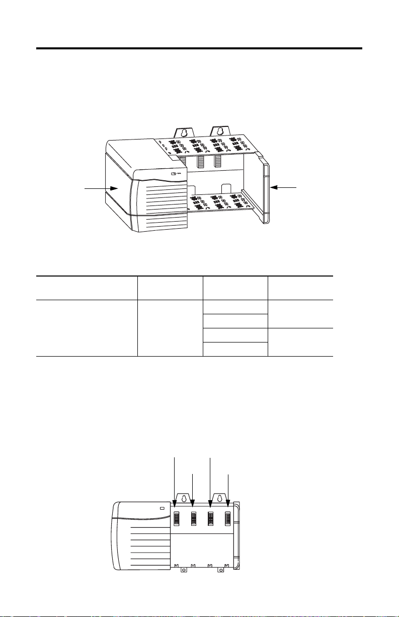
Module Features
1756-CLX/C module features include:
• NeXUS (ADP) messaging encapsulated within standard UDP/IP protocol
• interfacing via Ethernet media
• communication to and from ControlLogix controllers in the same chassis
• battery backed-up SRAM
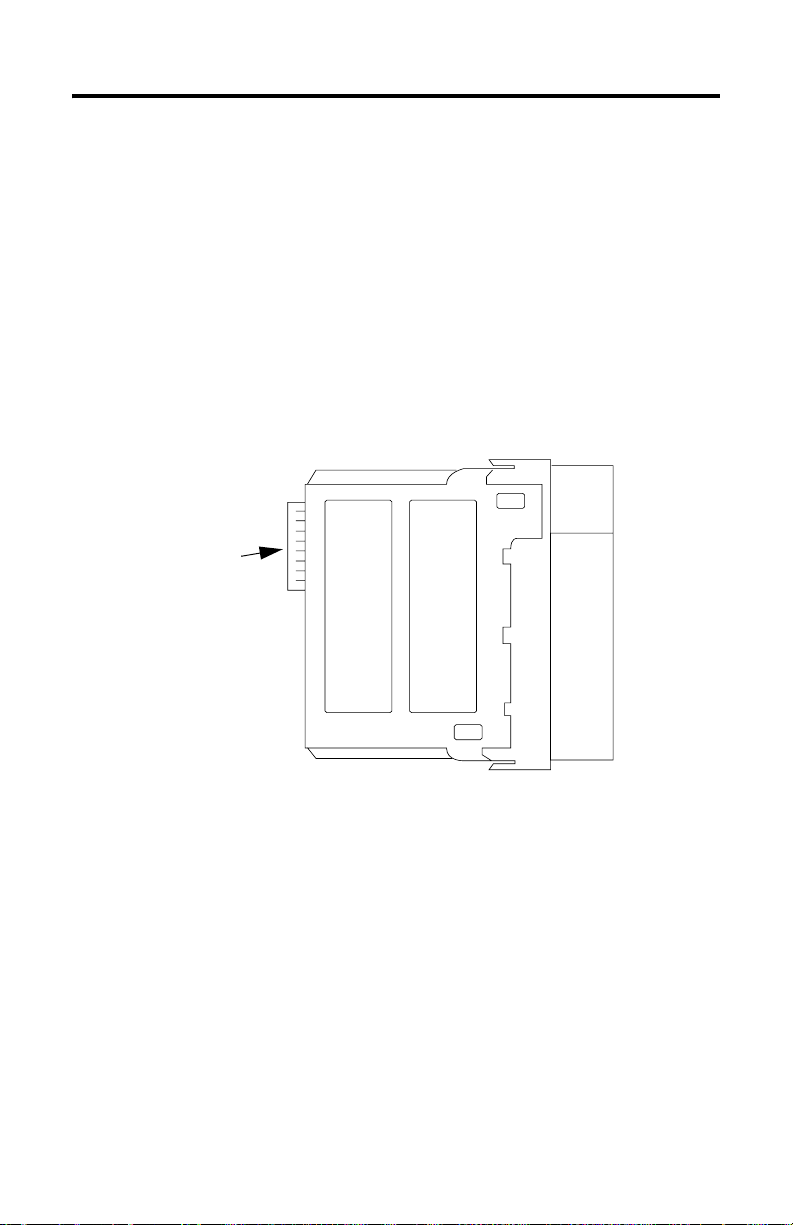
Backplane connector
(interface to the
ControlLogix backplane)
Publication 1756-UM524B-EN-P - December 2008
Page 15
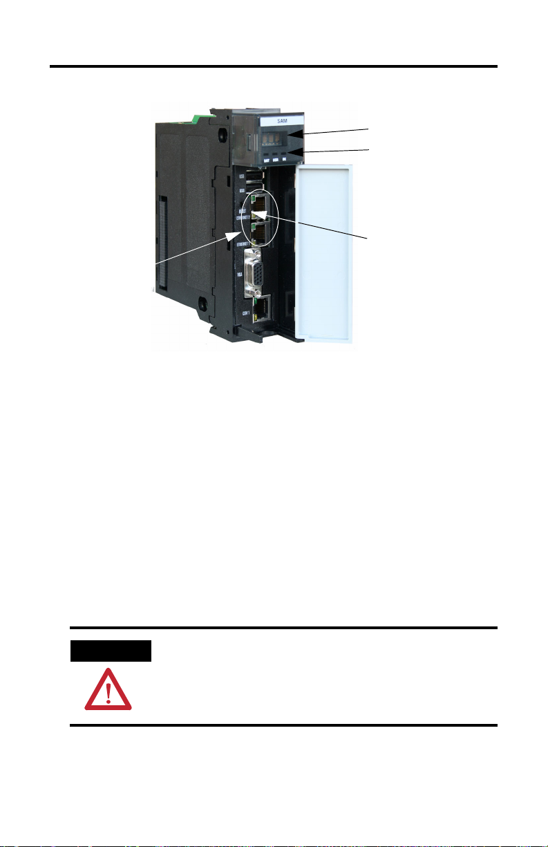
About the 1756-CLX/C Module 1-3
Alpha-numeric display
Status indicators
Ethernet port with
status indicators
Reset Switch
view; actual switch is
(schematic
inside module)
Some Points to Remember
Remember the following points about the 1756-CLX/C module:
• the module is not supported by RSLinx or RSNetworx software
• the module does not support bridging between NeXUS and ControlNet, DeviceNet,
EtherNet/IP, or any other network
• the module does not support bridging between NeXUS sub-nets (i.e., bridging
between 1756-CLX/C modules located in the same chassis)
• the maximum NeXUS (ADP) message size is 1024 bytes
• data rate is 10Mb/sec.; maximum data rate is 100Mb/sec.
• minimum module data transfer rate is 10 packets/sec.
• the module supports a maximum of 32 TCDs
• one Logix controller can own only one 1756-CLX/C module
ATTENTION
Use only the Ethernet connector on the module. Do not use other
connectors.
Publication 1756-UM524B-EN-P - December 2008
Page 16

1-4 About the 1756-CLX/C Module
About the Battery
The 1756-CLX/C module uses a rechargeable lithium vanadium pentoxide battery, which,
when fully charged, provides backup power for the SRAM memory for approximately 21
days. The module must be powered for approximately 20 hours before the battery
becomes fully charged. The battery is not accessible, and should last for the life of the
module.
ATTENTION
The lithium battery is not user-replaceable. Do not attempt to access or
replace it. Lithium batteries can be hazardous to humans and the
environment, and should always be handled and disposed of properly.
Hardware/Software Compatibility
The 1756-CLX/C module is compatible with the following firmware versions and
software releases. Contact Rockwell Automation if you need software or firmware
upgrades to use this equipment.
Product Firmware version/software release
ControlLogix Controller 7.09 or higher
RSLogix5000 Software 7.02 or higher
Publication 1756-UM524B-EN-P - December 2008
Page 17
About the 1756-CLX/C Module 1-5
Preventing Electrostatic Discharge
This module is sensitive to electrostatic discharge.
ATTENTION
Preventing Electrostatic Discharge
This equipment is sensitive to electrostatic discharge, which can cause
internal damage and affect normal operation. Follow these guidelines
when you handle this equipment:
• Touch a grounded object to discharge potential static.
• Wear an approved grounding wrist strap.
• Do not touch connectors or pins on component boards.
• Do not touch circuit components inside the equipment.
• If available, use a static-safe workstation.
• When not in use, store the equipment in appropriate static-safe
packaging.
Removal and Insertion Under Power
ATTENTION
We do not recommend that you install or remove the module under
power.
Publication 1756-UM524B-EN-P - December 2008
Page 18
1-6 About the 1756-CLX/C Module
1756-CLX/C Module Architecture
The figure below shows how the various components of a system using the 1756-CLX/C
module interact.
Backplane
Backplane
communication
Application (ladder)
Tags (data)
Logix5000 Controller
1756-CLX/C API
1756-CLX/C
module
1756-CLX/C Dlink
Backplane
communication
1756-CLX/C
message handling
SMG/BS
Ethernet port
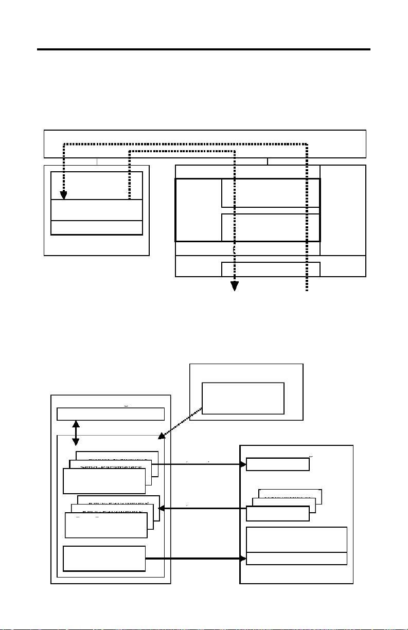
Configuration Overview
The figure below shows an overview of the configuration process.
Development PC
Setup
(DF, TCD)
IP Address
Data field
ControlLogix tools
Created at sending
Handle (send)
Created at startup
Handle (receive)
Data field (local only) and
multi-cast groups
IP Address and mask
Logix5000 Controller
Application ladder
Ta gs
Send parameters
(DF, MCG, TCD)
Receive parameters
(DF, TCD)
Parameters
(Node, TCP/IP)
(DF, MCG, TCD)
1756-CLX/C
module
Windows
NT 4.0
(UDP/IP)
Publication 1756-UM524B-EN-P - December 2008
Page 19
About the 1756-CLX/C Module 1-7
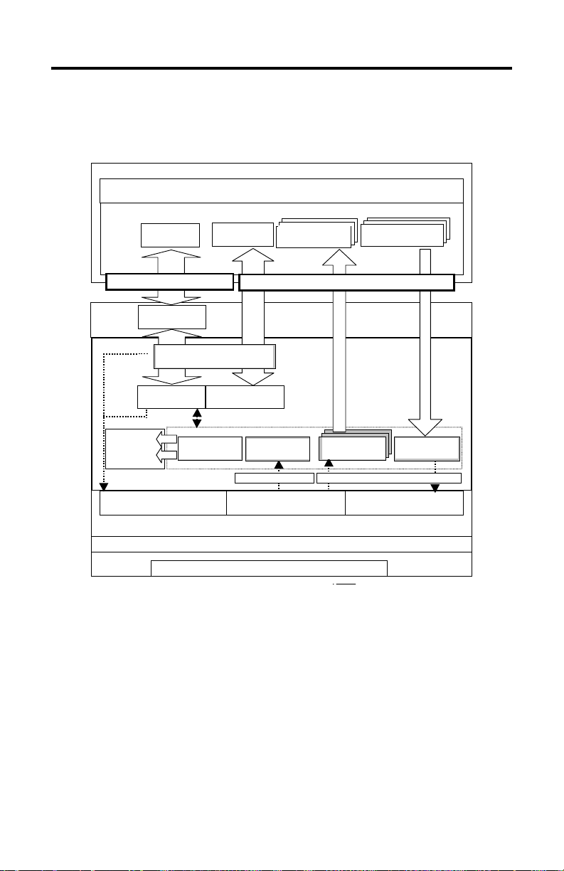
Process Overview
The figure below shows the flow of data to and from the 1756-CLX/C module.
Control Logix
ControlLogix
Application ladder
Application (Ladder)
Tags
System Status
System status
(NX20 - NX51)
NX20
NX51
System
System config.
Configuration
(NX00 - NX07)
07
NX00
TAGs
Recv-Parameters
Recv. parameters and
and data NX90,91
data (NX90 and NX91)
Send-Parameters
Send parameters and
and data NX80
data (NX90 and NX91)
Connected Data Transfer
Connected data transfer
System status
System Status
NX51
NX20
(NX20 - NX51)
1756-CLX/C module
NX/SAM
Shared
Shared
memory
System Status
Memory
System status
NX20
NX51
(NX20 - NX51)
LED segment
LED
display
Segment
Display
Functions to Start/Stop
Functions to
NX Dlink
start/stop NX Dlink
(nx_sam_mon.exe)
Unconnected Data Transfer
Management process
Management Process
(nx_sam_man.exe)
(nx_sam_man.exe)
Monitor Process
Monitor process
(nx_sam_mon.exe)
System Configuration
System config. (NX00
NX Dlink daemons and library
Windows NT 4.0 with SP6a (UDP/IP)
Windo ws NT4.0 with SP6a (UDP/IP)
NX00
07
- NX07)
System Transaction
Sys. transact. recv.
Recv Process
(nx_sam_mon.exe)
(nx_sam_srecv .exe)
System Transaction Transaction Data
System transaction Transaction data
Functions to receive
Functions
to receive
NX Dlink daemons and library
Ethernet port
Ethernet Port
Unconnected data transfer
Recv- Process
Receive process
(nx_sam_recv.exe)
(nx_sam_recv.exe)
Functions to send
Functions
Send -Process
Send process
(nx_sam_send.exe)
(nx_sam_send.exe)
to send
1756-CLX/C module
56SAM
Publication 1756-UM524B-EN-P - December 2008
Page 20

1-8 About the 1756-CLX/C Module
Notes:
Publication 1756-UM524B-EN-P - December 2008
Page 21

Chapter
Install the 1756-CLX/C Module
What This Chapter Contains
This chapter describes how to install the 1756-CLX/C module into a ControlLogix
chassis.
For information about this topic See page
Identify Module Components 2-1
Install and Connect the Chassis and Power Supply 2-2
Determine Module Slot Location 2-2
Install the Module in the Chassis 2-3
Apply Power to the Module 2-3
Removal and Insertion under Power 2-4
Make the Ethernet Connection 2-4
Remove or Replace the Module (When Applicable) 2-5
Check Power Supply and Module Status 2-6
2
Identify Module Components
Refer to Module Features on page 1-2 for an illustration that will help you identify the
module components.
About the Jumpers
ATTENTION
All jumpers on the 1756-CLX/C module are factory-set and should not
be changed. If you change a jumper by mistake, refer to Appendix B of
this manual to reset it to the proper position.
Publication 1756-UM524B-EN-P - December 2008
Page 22
2-2 Install the 1756-CLX/C Module
Install and Connect the Chassis and Power Supply
Before you install the module, you must install and connect a ControlLogix chassis and
power supply.
Power Supply
20805-M
1756-A4 Chassis
For information on installing these products, refer to the publications listed in the
following table.
Chassis
Typ e
Series B: 1756-A4, -A7, -A10,
-A13, -A17
Chassis
Installation
Pub. No.
1756-IN08C
Power
Supply
1756-PA72/B Pub. No.
1756-PB72/B
1756-PA75/A Pub. No.
1756-PB75/A
Power Supply
Installation
1756-IN078B
1756-IN596A
Determine Module Slot Location
You can install the module in any slot in the ControlLogix chassis.The figure below shows
chassis slot numbering in a 4-slot chassis. Slot 0 is the first slot and is always the left-most
slot in the rack (the first slot to the right of the power supply).
Slot 0
Power Supply
Slot 1
Slot 2
Slot 3
Publication 1756-UM524B-EN-P - December 2008
Chassis
Page 23
Install the 1756-CLX/C Module 2-3
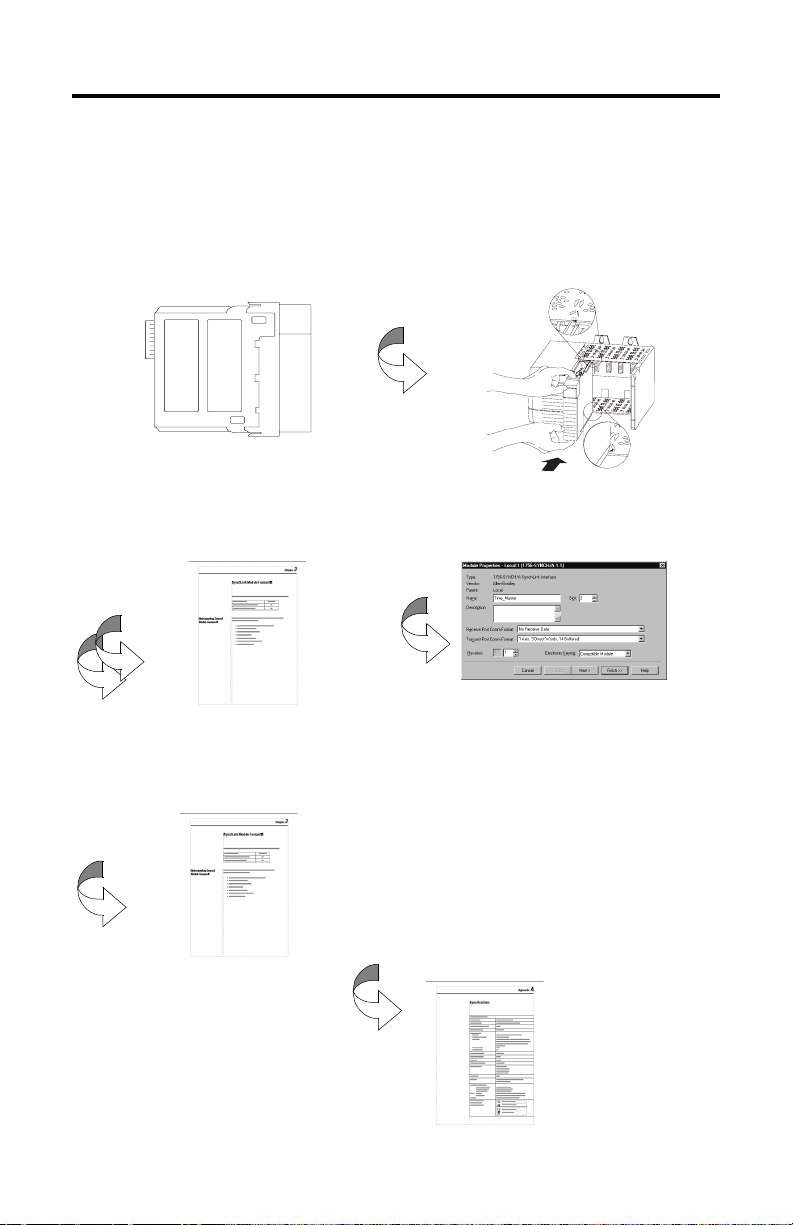
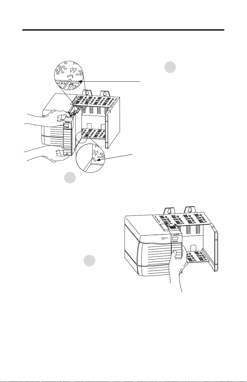
Install the Module in the Chassis
1
Align the circuit board with top and
bottom guides in the chassis.
Circuit Board
31275-M
2
Slide the module into the chassis. Make sure the module backplane connector properly
connects to the chassis backplane. Check that the holding clips on the top and bottom of the
module are securely in the locking holes of the rack.
3
The module is properly installed when
it is flush with the power supply or other
installed modules.
31276-M
Apply Power to the Module
Turn ON power. The 1756-CLX/C module performs a self-test. If the module is operating
properly, the OK LED turns GREEN.
Publication 1756-UM524B-EN-P - December 2008
Page 24

2-4 Install the 1756-CLX/C Module
Removal and Insertion under Power
WARNING
We do not recommend that you install or remove the module under
power.
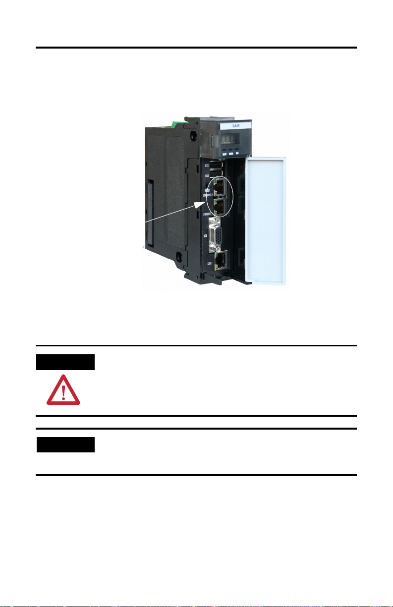
Make the Ethernet Connection
Wire the Ethernet Connector
The 1756-CLX/C module has an Ethernet port you will use to connect to the NeXUS
network. Use an RJ45 connector to connect to the Ethernet network. Wire the appropriate
connector as shown below:
1 ------ TD+
2 ------ TD3 ------ RD+
4 ------ NC
5 ------ NC
6 ------ RD7 ------ NC
8 ------ NC
For detailed connnection information, refer to the EtherNet/IP Media Planning and
Installation Guide, publication ENET-IN001A-EN-P.
8
1
RJ 45
Publication 1756-UM524B-EN-P - December 2008
Page 25
Install the 1756-CLX/C Module 2-5
Plug in the Connector
Plug the Ethernet connector into the port.
Ethernet port
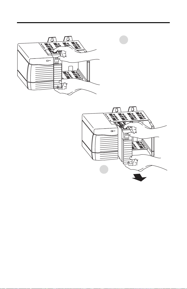
Remove or Replace the Module (When Applicable)
ATTENTION
IMPORTANT
Before you remove the module, you must disconnect the Ethernet
cable.
If you are replacing an existing module with an identical one, and you
want to resume identical system operation, you must install the new
module in the same slot.
Publication 1756-UM524B-EN-P - December 2008
Page 26
2-6 Install the 1756-CLX/C Module
1
Push on upper and lower module tabs to
disengage them.
31277-M
2
Slide module out of chassis.
31278-M
Check Power Supply and Module Status
Refer to chapter 5 to use the status indicators to determine that the 1756-CLX/C module is
operating correctly.
Publication 1756-UM524B-EN-P - December 2008
Page 27

Chapter
About the NeXUS Network
What This Chapter Contains
This chapter provides a brief overview of the NeXUS network. The following table
describes what this chapter contains and where to find it.
For information about this topic: See page:
Protocol Structure 3-1
Supported Services 3-2
Network Organization 3-3
Supported ADP Message Types 3-4
Configuration Requirements 3-4
For More Information 3-8
3
Protocol Structure
The NeXUS network is a TCP/IP over Ethernet type LAN with a manufacturing message
transfer protocol, known as NeXUS, on top, as shown in the table below. This protocol is
known as the Autonomous Decentralized Protocol, or ADP.
Publication 1756-UM524B-EN-P - December 2008
Page 28
3-2 About the NeXUS Network
OSI Layer NeXUS Network Protocol Comments
Layer 7 - Application NEXUS or ADP See the latest copy of the following
Layer 6 - Presentation Not implemented
Layer 5 - Session Not implemented
Layer 4 - Transport UDP and TCP Most ADP messages are transferred
Layer 3 - Network IP
Layer 2 - Data Link IEEE/802.3 - Ethernet
Layer 1 - Physical IEEE/802.3 - Ethernet
Physical Medium IEEE/802.3 - Ethernet
ADP specification, available at
http://www.mstc.or.jp/jop/misc/spec-e
.html:
Manufacturing Science and
Technology Center, Japan FA Open
Systems Promotion Group,
Distributed Manufacturing
Architecture Committee,
“Specifications for Autonomous
Decentralized Protocol”, R. 3.0,
MSTC/JOP (September 30, 1999).
using the UDP protocol; some are
transferred using the TCP protocol
Supported Services
The ADP protocol provides to application programs 2 means of message transmission:
peer-to-peer and multicast. Because the peer-to-peer message transfer requires a
connection-oriented service as an underlayer, it uses the TCP protocol.
Since multicast transmission is connectionless, multicast messages are sent and received
using the UDP protocol. As with any connectionless service, delivery and sequence of
messages is not guaranteed. Nor is there a flow control mechanism.
TIP
Publication 1756-UM524B-EN-P - December 2008
The 1756-CLX/C module supports multicast transmission services
only.
Page 29

About the NeXUS Network 3-3
Network Organization
Looking from the top down, a NeXUS network is viewed as a system of islands called
domains, interconnected via a wide area network. Each domain is uniquely identified by a
domain number (DMN), which ranges from 1 to 64. The domain number must be provided
in all ADP PDU headers. DMN 0 is reserved for the domain considered within the scope
of the ADP specification.
A domain is divided into data fields. A data field is an area within which a group of logical
nodes communicates with each other via multicast or peer-to-peer messages. A domain is
uniquely identified by a data field number (DFN) which ranges from 1 through 255 and
must be provided in all ADP PDU headers. One data field is configured per network or
sub-network address of the IP address.
Only nodes belonging to the same data field can communicate with each other. A node can
belong to more than one data field. Relative to a node, a data field can be local or remote
(for example, connected to the node via a router). Only local data fields are considered
within the scope of the ADP specification.
To support multicast communication, nodes within a data field are organized into
multicast groups. A node can be a member of more than one multicast group. A multicast
group is uniquely identified as a multicast group number, or MGN, which ranges from 1 to
255. The MGN must be provided in all multicast ADP PDU headers.
Each NeXUS node, also called a logical node, is uniquely identified by a logical node
number, or LNN, which ranges from 1 to 4095. The LNN must be provided in all ADP
PDU headers.
The user normally assigns and manages DFNs, LNNs, and MGNs. DMN, DFN, and LNN
form the source address (SA). DMN, DFN, and MGN form the destination address (DA)
of an ADP PDU header.
Publication 1756-UM524B-EN-P - December 2008
Page 30
3-4 About the NeXUS Network
Supported ADP Message Types
The 1756-CLX/C module supports the following communication features referenced in
the ADP specification:
Communication
Feature
Multicast
communication
Alive signal Base-1 4.2 Supported Not supported
Communication
Feature
Test support 4.5 Supported Supported Supported Not supported
Maximum
message length
Class Clause (in ADP
Base-1 4.1 Supported Supported
Clause (in ADP
specification)
- (MTU-92) bytes (MTU-92) bytes
specification)
Requirements for Conformance
Multicast Alive signal
Transmission Reception Transmission Reception
Requirements for Conformance
Transmission Reception
Configuration Requirements
Before you can use your 1756-CLX/C module, you must configure its IP address,
gateway, and subnet mask by specifying parameters NX00 through NX02 on the
Logix5000 controller. Refer to Appendices D and E of this manual for definitions of these
parameters.
IP Address
The IP address identifies each node on the TCP/IP network (or system of connected
networks). Each TCP/IP node on a network must have a unique IP address.
The IP address is 32 bits long and is composed of a net ID, host ID, and/or a multicast ID.
Each network can be a Class A, B, C, or D format. The class of the network determines
how an IP address is formatted.
Publication 1756-UM524B-EN-P - December 2008
Page 31

About the NeXUS Network 3-5
16
16
16
16
24
host ID
24
host ID
24
host ID
24
host ID
Class A
Class B
Class C
Class D
1
0
1
0
1
1
0
1
111
Network ID
Network ID
0
0
0
1
0
1
0
8
8
8
Network ID
Multicast ID
Each node on the same physical network must have an IP address of the same class and
must have the same nework or multicast ID. Each node on the same network must have a
different host ID, giving it a unique IP address.
IP addresses are written as four decimal integers (0-255), separated by periods, where each
integer gives the value of one byte of the IP address.
EXAMPLE
For example, the 32-bit IP address:
10000010 00000000 00000000 00000001 is written as 130.0.0.1.
You can distinguish the class of an IP address from the first integer in its dotted-decimal
IP address as follows:
Range of first integer Class
0 -127 A
128 -191 B
192 - 223 C
224 - 239 D
240 - 255 Experimental
31
31
31
31
TIP
Contact your network administrator or the Network Information Center
for a unique fixed IP address to assign to your module.
For more information on Internet addressing, see Comer, Douglas E; Internetworking with
TCP-IP, Volume 1: Protocols and Architecture; Englewood Cliffs, N.J.: Prentice-Hall,
1990.
Publication 1756-UM524B-EN-P - December 2008
Page 32

3-6 About the NeXUS Network
Gateways
A gateway connects individual physical networks into a system of networks. When a node
needs to communicate with a node on another network, a gateway transfers the data
between the two networks. The following figure shows gateway G connecting Network 1
with Network 2.
A
128.1.0.1
Network 1
128.1.0.2
G
B
128.2.0.1 128.2.0.2
C
128.2.0.3
Network 2
When host B with IP address 128.2.0.1 communicates with host C, it knows from C’s IP
address that C is on the same network. In an Ethernet environment, B can then resolve C’s
IP address to a MAC address and communicate with C directly.
When host B communicates with host A, it knows from A’s IP address that A is on another
network (the net IDs are different). In order to send data to A, B must have the IP address
of the gateway connecting the two networks. In this example, the gateway’s IP address on
Network 2 is 128.2.0.3.
The gateway has two IP addresses (128.1.0.2 and 128.2.0.3). The first must be used by
hosts on Network 1 and the second must be used by hosts on Network 2. To be usable, a
host’s gateway must be addressed using a net ID matching its own.
Publication 1756-UM524B-EN-P - December 2008
Page 33

About the NeXUS Network 3-7
Subnet Mask
Subnet addressing is an extension of the IP address scheme that allows a site to use a
single net ID for multiple physical networks. Routing outside of the site continues by
dividing the IP address into a net ID and a host ID via the class. Inside a site, the subnet
mask is used to redivide the IP address into a custom net ID portion and host ID portion.
Take Network 2 (a Class B network) in the previous example and add another physical
network. Selecting the following subnet mask would add two additional net ID bits
allowing for four physical networks:
EXAMPLE
Two bits of the Class B host ID have been used to extend the net ID. Each unique
combination of bits in the part of the host ID where subnet mask bits are 1 specifies a
different physical network.
The new configuration is:
11111111 11111111 11000000 00000000 = 255.255.192.0
A
128.1.0.1
Network 1
128.1.0.2
G
B
128.2.64.1 128.2.64.2
C
128.2.64.3
Network 2.1
G2
D
128.2.128.1 128.2.128.2
E
128.2.128.3
Network 2.2
A second network with Hosts D and E has been added. Gateway G2 connects Network 2.1
with Network 2.2. Hosts D and E will use Gateway G2 to communicate with hosts not on
Network 2.2. Hosts B and C will use Gateway G to communicate with hosts not on
Network 2.1. When B is communicating with D, G (the configured Gateway for B) will
route the data from B to D through G2.
Publication 1756-UM524B-EN-P - December 2008
Page 34

3-8 About the NeXUS Network
For More Information
For more information about Ethernet, refer to the following publications:
Publication data ISBN
Internetworking with TCP/IP
Vol. 1, 2nd ed.
by Douglas E. Comer
The Ethernet Management Guide –
Keeping The Link
An Introduction to TCP/IP ISBN 3-540-96651-X
Computer Networks
by Andrew S. Tanenbaum
ISBN 0-13-216987-8
ISBN 0-07-046320-4
ISBN 0-13-162959-X
Publication 1756-UM524B-EN-P - December 2008
Page 35

Chapter
4
Configure the 1756-CLX/C Module
What This Chapter Contains
This chapter describes why you must configure your 1756-CLX/C module and how to
configure it for use in the ControlLogix system.
For information about this topic See page:
Configure Your 1756-CLX/C Module 4-1
Create a New Module 4-2
View and Change Module Tags 4-5
Configure the Module IP Address 4-6
Configure Your 1756-CLX/C Module
You must configure your module upon installation. The module will not work until it has
been configured.
Configuration Software
Use RSLogix 5000 software to set configuration for your 1756-CLX/C module. You have
the option of accepting default configuration for your module or writing configuration
specific to your application.
Both options are explained in detail, including views of software screens, in this chapter.
Publication 1756-UM524B-EN-P - December 2008
Page 36

4-2 Configure the 1756-CLX/C Module
Overview of the Configuration Process
When you use the RSLogix 5000 software to configure a 1756-CLX/C module, you must
perform the following steps:
1. Create a new module.
2. Accept the default configuration or change it to specific configuration for the
module.
3. Edit configuration for a module when changes are needed.
4. Configure the module’s IP address.
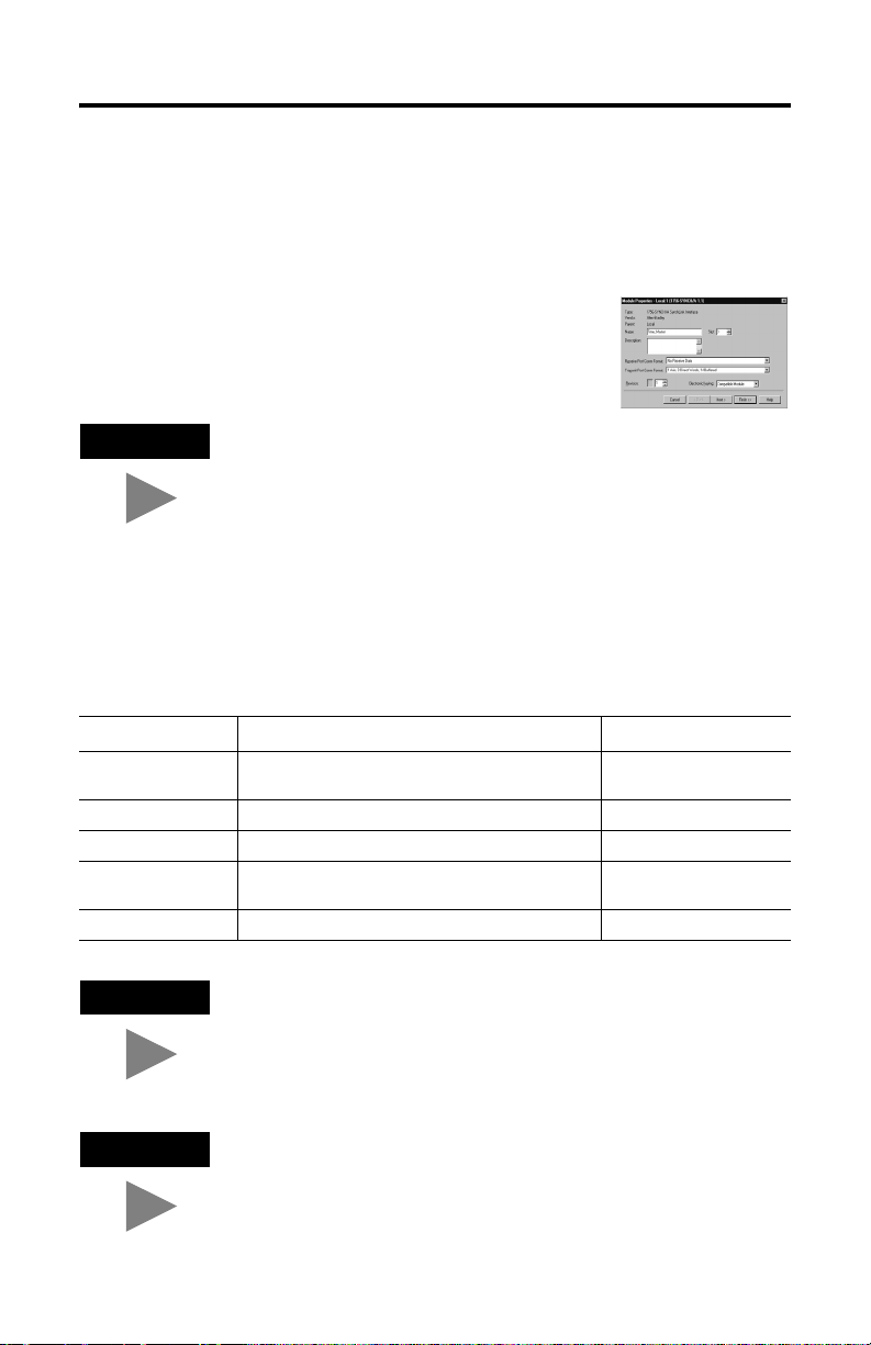
Create a New Module
After you have started RSLogix 5000 and created a controller, you must create a new
module. The wizard allows you to create a new module and write configuration. You can
use default configuration or write specific configuration for your application.
IMPORTANT
Publication 1756-UM524B-EN-P - December 2008
You must be offline when you create a new module
If you are not offline, use this
pull-down menu to go offline
Page 37

Configure the 1756-CLX/C Module 4-3
When you are offline, you must select a new module.
1. Select I/O Configuration.
2. Click on the right mouse
button to display the menu.
3. Select New Module
A screen appears with a list of possible new modules for your application. Select a module
from the list.
Click OK. The new module creation wizard appears. Enter information as follows:
in this field enter
Name an optional name
Description an optional description
Input
Assembly Instance 1
Size 4
Output
Assembly Instance 2
Size 5
Configuration
Assembly Instance 4
Size 0
Publication 1756-UM524B-EN-P - December 2008
Page 38

4-4 Configure the 1756-CLX/C Module
After you name the page, this screen appears
Inhibit the connection to
the module here
If you want a Major
Fault on the Controller
to occur if there is
connection failure with
the I/O module, click
here
This Fault box is empty when you are
offline. If a fault occurs while the
module is online, the type of fault will
be displayed here
Click here to move to the next page
Adjust the Requested
Packet Interval here.
The default RPI is 5ms.
This screen is used
during online
monitoring but not initial
configuration
Click here to move to the next page
Publication 1756-UM524B-EN-P - December 2008
Page 39

Configure the 1756-CLX/C Module 4-5
View and Change Module Tags
When you create a module, a set of tags are created by the ControlLogix system that can
be viewed in the Tag Editor of RSLogix 5000. Each configurable feature on your module
has a distinct tag that can be used in the processor’s ladder logic.
You can access a module’s tags through RSLogix 5000 as shown below.
1. Select Controller Tags.
2. Click on the right mouse
button to display the menu.
3. Select Monitor Tags.
You can view the tags from here
Click on the slot number of
the module you want to see
Because the process of viewing and changing a module’s configuration tags is broader in
scope than can be addressed in this chapter, refer to Appendix D for more information and
sample tag collections.
Publication 1756-UM524B-EN-P - December 2008
Page 40

4-6 Configure the 1756-CLX/C Module
Configure the Module IP Address
Before you can use your 1756-CLX/C module, you must configure its IP address,
gateway, and subnet mask by specifying parameters NX00 through NX02 on the
Logix5000 controller. Refer to Appendices D and E of this manual for definitions of these
parameters.
Publication 1756-UM524B-EN-P - December 2008
Page 41

Chapter
5
Status Indicators and
Troubleshooting
What This Chapter Contains
This chapter shows you the status indicators on the 1756-CLX/C module, and provides
basic troubleshooting procedures.
Alpha-numeric display
LED status indicators
Communication port
status indicators
For information about this topic See page
Use the LED Status Indicators 5-2
Use the Communications Port Status Indicators 5-3
Use the Alpha-numeric Display 5-3
Publication 1756-UM524B-EN-P - December 2008
Page 42

5-2 Status Indicators and Troubleshooting
Use the LED Status Indicators
The 1756-CLX/C module has the following LED status indicators. Use these indicators to
troubleshoot module status.:
Table 5.A LED Status Indicators
This LED When Means So you should
BAT (RED) ON The battery is low. Replace the module.
USR
(GREEN)
OK
(STATUS)
The battery is charging. The BAT
LED turns OFF within a few
minutes after power is applied.
OFF The Battery is charged.
The module is not powered up.
ON/OFF Data is being sent or received
OFF No data is being sent or received
GREEN The module is operating
RED The module has experienced an
OFF The module is not powered up. Apply power to the module.
over the NeXUS port.
over the NeXUS port.
The module is not powered up.
correctly.
error.
Wait for the battery to finish
charging.
Do nothing. The module is ready
for use.
Apply power to the module.
Do nothing. The module is
operating correctly.
Check the Communication port
LEDs. If:
•
LEDs are working properly,
restart the module
•
LEDs are not working
properly, follow the
instructions in
page 5-3
•
the problem persists, replace
the module
Apply power to the module.
Do nothing. The module is ready
for use.
Restart the module. If the
problem persists, replace the
module.
Ta bl e 5.B on
Publication 1756-UM524B-EN-P - December 2008
Page 43

Status Indicators and Troubleshooting 5-3
Use the Communications Port Status Indicators
The 1756-CLX/C module has the following communications port status indicators. Use
these indicators to troubleshoot module communication:
Table 5.B Communication Port Status Indicators
This LED When operating like this, means So you should
10/100 (GREEN)
(Top LED)
ACTIVE (YELLOW)
(Bottom LED)
•
This LED will be ON if 100BASE-TX
link is detected and OFF if a
10BASE-T link is detected. If the link
fails while in Auto-negotiation, this
LED will keep the last valid link state.
If the 100BASE-TX link is forced, this
LED will be ON, regardless of the
link status.
•
This LED will be OFF if the
10BASE-T link is forced, regardless
of the link status.
This LED is OFF until a valid link has
been detected. After a valid link has
been detected, the LED will remain ON,
blinking ON and OFF when network
activity is detected.
Do nothing. The module is operating
correctly.
If this link is not valid (LED is OFF),
do the following:
•
Check the Ethernet cable.
Replace if necessary
•
Check the Communications port
on the device connected to the
module
•
If the problem persists, replace the
module.
Use the Alpha-numeric Display
The 1756-CLX/C module has a 4-character alpha-numeric display on the front panel. Use
this display to check system health..
Table 5.C Alpha-numeric Display Indicators
This message on
the alpha-numeric
display
RUN Enabled Running No Do nothing.
ERR Enabled Running Ye s See Table 5.D for error
STOP Disabled N/A N/A Restart the module. If
No activity Disabled N/A N/A Restart the module. If
means that
1756-CLX/C
software is
and NX Dlink
software is
Publication 1756-UM524B-EN-P - December 2008
and an
error is
present
So you should
codes.
problem persists,
replace the module.
problem persists,
replace the module.
Page 44

5-4 Status Indicators and Troubleshooting
Table 5.D Firmware error codes
Error type Error
contents
Configu-
Configuration
ration Error
Error
System
NX DLINK is
Online
inactive
Error
Data Buffer
Overflowed
Data Buffer
Upper Limit
Data Buffer
Lower Limit
Receive Limit
Over
of Data Handle
MC Receive
Number
has missed
CPU Temp Over
Limit
CPU Temp
Upper Limit
Send/
CPU Temp
Receive
Lower Limit
Error
Send Error
Receive Error
Module
stopped
Alpha-
NX46_
NX60_
numeric
System
display
error
ERR ON Error_
ERR ON 0x11008000 E 0x11008000 N/A N/A NXDlink Majo r Fault
RUN OFF N/A W 0x11008001 N/A N/A NXDlink Warn ing
RUN OFF N/A E 0x11008002 N/A N/A NXDlink Minor Fault
RUN OFF N/A I 0x11008003 N/A N/A NXDlink Informa-
RUN OFF N/A W 0x12008004 N/A N/A N/A Wa rnin g
RUN OFF N/A I 0x11008004 N/A N/A NXDlink Informa-
RUN OFF N/A W 0x4e000001 N/A N/A NX SAM Wa rnin g
RUN OFF N/A E 0x4e000002 N/A N/A NX SAM Minor Fault
RUN OFF N/A I 0x4e000003 N/A N/A NX SAM Informa-
RUN OFF N/A N/A N/A See Table 5.F NXDlink Individ-
STOP OFF N/ A N/A N/A N/A N/A N/A
NX63_
System
status
error code
level
N/A N/A N/A N/A NX SAM See
Code
NX64_
NX61_
VX62_
Event
Status
code
Send
error code
Receive
error code
log
source
User
action
Table 5.E
tion
tion
tion
ual error for
each handle.
See
Table 5.F.
Table 5.E Module error codes
No. Error code Decription User action
1 0x00000001 Incorrect Data Setting for
NX00_Node_Name_param
2 0x00000002 Incorrect Data Setting for
3 0x00000003 Incorrect Data Setting for
NX01_IP_Address_Param
NX02_Subnet_Mask_Param
4 0x00000004 Incorrect Data Setting for
NX03_Node_Param[0] “Logical
Node Number”
5 0x00000005 Incorrect Data Setting for
NX03_Node_Param[1] “Local Data
Field Number”
Publication 1756-UM524B-EN-P - December 2008
Correct the Data Setting for
NX00_Node_Name_param
Correct the Data Setting for
NX01_IP_Address_Param
Correct the Data Setting for
NX02_Subnet_Mask_Param
Correct the Data Setting for
NX03_Node_Param[0]
Correct the Data Setting for
NX03_Node_Param[1]
Page 45

Status Indicators and Troubleshooting 5-5
Table 5.E Module error codes
No. Error code Decription User action
6 0x00000006 Incorrect Data Setting for
7 0x00000007 Incorrect Data Setting for
8 0x00000008 Incorrect Data Setting for
9 0x00000009 Incorrect Data Setting for
10 0x0000000a Incorrect Data Setting for
11 0x00000010 Multicast_Group_Number is out of
12 0x00000011 Online Port Number is out of range
13 0x00000012 Test Port Number is out of range
14 0x00000013 S/R OK Flag Value is out of range
15 0x00000014 Multicast_Group_Number is
16 0x00000015 Port Number is overlapped Correct the Port Number for
17 0x00000090 Low Limit Value is out of range for
18 0x00000091 High Limit Value is out of range for
19 0x0000FFFF System has corrupted during the
NX03_Node_Param[2] “Node
Mode at start up”
NX03_Node_Param[4] “Message
Send Port Number”
NX03_Node_Param[5] “Node Alive
Receive Port Number”
NX03_Node_Param[6] “Node Alive
Interval”
NX03_Node_Param[7] “Node Alive
Count”
range for
NX06_Multicast_Group_Param
for NX06_Multicast_Group_Param
for NX06_Multicast_Group_Param
for NX06_Multicast_Group_Param
overlapped for
NX06_Multicast_Group_Param
NX07_Overflow_Param[0] “Low
Limit”
NX07_Overflow_Param[1] “High
Limit”
NX Dlink Initialization
Correct the Data Setting for
NX03_Node_Param[2]
Correct the Data Setting for
NX03_Node_Param[4]
Correct the Data Setting for
NX03_Node_Param[5]
Correct the Data Setting for
NX03_Node_Param[6]
Correct the Data Setting for
NX03_Node_Param[7]
Correct the Data Number for
Entry0~7
Multicast_Group_Number
Correct the Data Number for
Entry0~7 Online Port Number
Correct the Data Number for
Entry0~7 Test Port Number
Correct the Data Value for
Entry0~7 S/R OK FlagValue
Correct the Data Number for
Entry0~7
Multicast_Group_Number
Entry0~7and also check the value
for NX03_Node_Param[4] and
NX03_Node_Param[5]
Correct the Data Setting for
NX07_Overflow_Param[0]
Correct the Data Setting for
NX07_Overflow_Param[1]
Refer to Appendix C, Web Page
Diagnostics
Publication 1756-UM524B-EN-P - December 2008
Page 46

5-6 Status Indicators and Troubleshooting
Table 5.F Send/receive error codes
No. Error code Description User action
1 0x00000000 Data was sent or received properly N/A
2 0x81000005 Multicast_Group_Number is not
3 0x81000006 TCD Number is not specified or out
4 0x82000011 TCD Number is overlapped Correct the TCD Number of the
5 0x84000002 Error has occurred when creating
6 0x84000003 Error has occurred when attaching
specified or out of range
of range
the socket or during the socket
communication
the common memory
Correct the the
Multicast_Group_Number of the
related Handle
Correct the TCD Number of the
related Handle
related Handle
Consult Rockwell Automation
technical support
Consult Rockwell Automation
technical support
Publication 1756-UM524B-EN-P - December 2008
Page 47

Appendix
Specifications
Module Location 1756 ControlLogix chassis
Maximum Backplane Current 1A @ 5V dc
Maximum Power Dissipation 5W
Communication Ports Ethernet 10/100T IEEE 802.3
Battery Rechargeable Lithium Vanadium Pentoxide
Temperature Operating: 0 to 60 ° C
Form Factor Single Slot ControlLogix Module
Certifications
Storage: 0 to 80 ° C
UL Recognized Industrial Control
Component (pending)
CUL (pending)
Marked for all applicable directives
A
Publication 1756-UM524B-EN-P - December 2008
Page 48

A-2 Specifications
Notes:
Publication 1756-UM524B-EN-P - December 2008
Page 49

Appendix
B
Factory-set Jumpers
Jumpers on the 1756-CLX/C module are factory-set. If you change the jumper settings by
mistake, follow this procedure to reset them.
ATTENTION
Do not change the jumper positions. If you change a jumper position
by mistake, you must re-set it to the position shown below.
Publication 1756-UM524B-EN-P - December 2008
Page 50

B-2 Factory-set Jumpers
32-bit (shown)
16-bit (shown)
1756-CLX/C CON FIGURATION
JUMPER SETTINGS
Front of module
Publication 1756-UM524B-EN-P - December 2008
Page 51

Appendix
C
1756-CLX/C Web Interface
The 1756-CLX/C module’s web page offers extensive internal and network diagnostics.
To view the web pages, enter the module’s IP address into your web browser. You can
access the following web pages.
For information about this topic: See page:
User Screens C-1
User Screens
Figure C.1 Title screen
Publication 1756-UM524B-EN-P - December 2008
Page 52

C-2 1756-CLX/C Web Interface
Figure C.2 Data Field Status screen
Publication 1756-UM524B-EN-P - December 2008
Page 53

Figure C.3 Multicast group statistics screen
1756-CLX/C Web Interface C-3
TIP
You can also access this screen by typing nxstat -m in a DOS window.
Publication 1756-UM524B-EN-P - December 2008
Page 54

C-4 1756-CLX/C Web Interface
Figure C.4 Transaction Statistics screen
TIP
You can also access this screen by typing nxstat -t in a DOS window.
Publication 1756-UM524B-EN-P - December 2008
Page 55

Figure C.5 Buffer Usage statiscs screen
1756-CLX/C Web Interface C-5
TIP
You can also access this screen by typing nxstat -b in a DOS window.
Publication 1756-UM524B-EN-P - December 2008
Page 56

C-6 1756-CLX/C Web Interface
Figure C.6 Handle Status and Statistics screen
TIP
You can also access this screen by typing nxstat -h or nxhdl in a DOS
window.
Publication 1756-UM524B-EN-P - December 2008
Page 57

Figure C.7 Event Log screen
1756-CLX/C Web Interface C-7
Publication 1756-UM524B-EN-P - December 2008
Page 58

C-8 1756-CLX/C Web Interface
Figure C.8 Technical Support Information screen
You can access this screen, type in the required information, then send this screen to
Technical Support.
Figure C.9 Clear Statistics screen
Publication 1756-UM524B-EN-P - December 2008
Page 59

Appendix
D
1756-CLX/C Module Backplane
Communication Tag List
The 1756-CLX/C module tags NX00 through NX91 are used for backplane (API)
communication, and should be defined in your ladder logic exactly as listed in Table D-A
in this Appendix. Refer to Appendix F for information on copying the tags and ladder
logic files from the .acd file supplied with the 1756-CLX/C module.
For information about this topic: See page:
About the Nexus Communication Flags (NX20 – NX91) D-2
ATTENTION
Failure to properly define the module tags NX00 through NX91 may
result in unpredictable module operation.
Publication 1756-UM524B-EN-P - December 2008
Page 60

D-2 1756-CLX/C Module Backplane Communication Tag List
G
X
About the Nexus Communication Flags (NX20 – NX91)
Boot /Reboot 1756-CLX/C Module Procedure
The following tags are applied for this sequence. Refer the timing chart for more details.
• NX20_Module_Enable
• NX40_Module_Enabled
• NX47_Module_Ready
• NX48_Module_Enable_Ack
Figure D.1 Boot and Parameter Configuration Timing Chart
Power on
1756-CLX/C
NX47_Module_
Ready
(BOOL)
(S/W of 56NE
RUN/PROG
Mode
S:FS (Fi rst Scan
Flag)
NX20_Module
_Enable
(BOOL)
NX48_Module_
Enable_Ack
(BOOL)
NX40_Module_
Enabled
(BOOL)
Change Par ameter
NX
OS SMG/BS
NX
)
Management
Process
PRO
NX
Confi gurati on
Check
RUN
OFF
NX Dlink
Initialization
NX
Initialization
ON
Configuration
Check
OFF
NX Dlink
InitializationNXInitialization
ON
Publication 1756-UM524B-EN-P - December 2008
Page 61

1756-CLX/C Module Backplane Communication Tag List D-3
G
F
W
NOFF
NOFF
Figure D.2 Operating System Reboot Timing Chart
Change Paramet er
(Node Name or IP addr ess)
Power o n
1756-CLX/C
ON
NX47_Module_
Ready
(BOOL)
56NEX S
RUN/PROG
Mode
S:FS ( First Sc an
Flag)
NX20_Module
_Enable
(BOOL)
NX48_Module_
Enable_Ack
(BOOL)
NX40_Module_
Enabled
(BOOL)
ON
OS Reboot SMG/BS NX
NX
Configuration
Check
PRO
RU
ON
OF
Management
Proce ss
NX
Configuration
Check
NX Dlin k
Initialization
NX
Initialization
O
Publication 1756-UM524B-EN-P - December 2008
Page 62

D-4 1756-CLX/C Module Backplane Communication Tag List
1756-CLX/C Module Configuration Check Procedure
The following tags are applied for this sequence. Refer the timing chart for more details.
• NX20_Module_Enable
• NX40_Module_Enabled
• NX48_Module_Enable_Ack
• NX46_System_Error
• NX60_System_Error_Code
Figure D.3 1756-CLX/C Configuration Check Timing Chart
CLX
Ta gs
1756-CLX/C
(1) Sets NX00-07 Tags for Parameter
Ladder
NX20_Module_Enable
(BOOL)
NX48_Module_
Enable_Ack
(BOOL)
NX40_Module_Enabled
(BOOL)
NX46_System_Error
(BOOL)
NX60_System_Error
Code(DI NT)
NX
Management
Process
(2) Set s NX20_Module_E nable
(3) Cl ears NX20_Modul e_Enable
(1) Set s NX48_Modul e_Enable_Ack
(2) Clears NX40_Module_Enabled
(3) Sets if NX Dlink configuration is in failure
If success NX60_System_Err or_Code
Clear, N X46_Syst em_Err or OFF
If failure NX60_System_Error_Code Set,
NX46_System_Error ON
Publication 1756-UM524B-EN-P - December 2008
Page 63

1756-CLX/C Module Backplane Communication Tag List D-5
1756-CLX/C System Error Procedure
The following tags are applied for this sequence. Refer the timing chart for more details.
• NX63_Status_Leve
• NX64_Status_Code
Figure D.4 1756-CLX/C System Error Timing Chart
NX63_Status_Level
(DINT)
NX64_Status_Code
(DI NT)
1756- CLX/C
NX
Mon i t o r
Process
(1) Sets NX63_Status_Level
(2) Sets NX64_Status_Code
(3) Displ ays t he Segment Dis play
Publication 1756-UM524B-EN-P - December 2008
Page 64

D-6 1756-CLX/C Module Backplane Communication Tag List
1756-CLX/C Module Sending Procedure
The following tags are applied for this sequence. Refer the timing chart for more details.
• NX30_Send_Request
• NX50_Send_Done
• NX61_Send_Error_Code
Figure D.5 1756-CLX/C Module Sending Procedure Timing Chart
Ladder
CLX
Tag s
1756-CLX/C
NX
Send-Process
Request Sending.
(1) Sets Send_D ata and Data Buffer
Size NX80 tags
(2) Sets N X30_Send_Request
NX30_Send_Request
(BOOL)
NX50_Send_Done
(BOOL)
NX61_Send_Error_Code
(DINT[32])
(1) Sends the data
(2) Sets NX61_S end_Error_Code
(3) Sets NX50_S end_Done
(1) Checks NX61_Send_Error_Code has not set Error
(2) Clears NX30_Send_Requ est.
0 if success, Error code if f ailure
(1) Clears NX61_ Send_Error_Code
(2) Clears NX50_ Send_Done
Publication 1756-UM524B-EN-P - December 2008
Page 65

1756-CLX/C Module Backplane Communication Tag List D-7
1756-CLX/C Module Receiving Procedure
The following tags are applied for this sequence. Refer the timing chart for more details.
• NX31_Receive_Done
• NX51_Receive_Request
• NX62_Receive_Error_Code
Figure D.6 1756-CLX/C Module Receiving Procedure Timing Chart
(1) Check NX62 _Receive_Error_C ode has
Ladder
CLX
Ta gs
1756-CLX/C
NX
Recv-Process
(xx:00-3 1)
NX31_Receive_Done
(BOOL)
NX51_Receive_
Request
(BOOL)
NX62_Receive_
Error_Code
(DINT[32])
(1) Receiving data
(2) If success
Sets NX91_Recei ve_Data_xx
Sets NX90_Rec eived_Data_size[ xx]
(3)Sets NX6 2_Receive_Error _Code
(4)Sets NX31_Receive_Request
not set Error, and read data from
NX91_Receive_D ata_xx( the si ze is set to
NX90_Received_D ata_size[xx] )
(2) NX31_Recei ve_Done ON
0 if success, Error code if failure
(xx:00-31)
(1) Clears NX62_Receive_Err or_Code
(2) Clears NX51_Receive_Request
Clears
NX31_Receive_D one
Publication 1756-UM524B-EN-P - December 2008
Page 66

D-8 1756-CLX/C Module Backplane Communication Tag List
Table D.A Module Backplane Communication Tag List
Tag N ame Data
NX00_Node_Name-Param SINT[10] Parameters for Node_Name - - -
NX00_Node_Name_Param[0] SINT 1st character of Node Name 5
NX00_Node_Name_Param[1] SINT 2nd character of Node Name 6
NX00_Node_Name_Param[2] SINT 3rd character of Node Name N
NX00_Node_Name_Param[3] SINT 4th character of Node Name E
NX00_Node_Name_Param[4] SINT 5th character of Node Name X
NX00_Node_Name_Param[5] SINT 6th character of Node Name (null)
NX00_Node_Name_Param[6] SINT 7th character of Node Name (null)
NX00_Node_Name_Param[7] SINT 8th character of Node Name (null)
NX00_Node_Name_Param[8] SINT 9th character of Node Name (null)
NX00_Node_Name_Param[9] SINT 10th character of Node Name (null)
NX01_IP_Address_Param INT[4] Parameters for IP_Address - - -
NX01_IP_Address_Param[0] INT 1st character of IP Address 192
NX01_IP_Address_Param[1] INT 2nd character of IP Address 168
NX01_IP_Address_Param[2] INT 3rd character of IP Address 0
NX01_IP_Address_Param[3] INT 4th character of IP Address 1
NX02_Subnet_Mask_Param INT[4] Parameters for Subnet_Address - - -
NX02_Subnet_Mask_Param[0] INT 1st character of Subnet Mask 255
NX02_Subnet_Mask_Param[1] INT 2nd character of Subnet Mask 255
NX02_Subnet_Mask_Param[2] INT 3rd character of Subnet Mask 255
NX02_Subnet_Mask_Param[3] INT 4th character of Subnet Mask 0
NX03_Node_Param DINT[16] Parameters related to Node - - -
NX03_Node_Param[0] DINT Logical Node Number <1 to 4095> 1
NX03_Node_Param[1] DINT Local Data Field Number <1 to 255> 1
NX03_Node_Param[2] DINT Node Mode at Startup
NX03_Node_Param[3] DINT Reserved 0
NX03_Node_Param[4] DINT Message Send Port Number
NX03_Node_Param[5] DINT Node Alive Receive Port Number
NX03_Node_Param[6] DINT Node Alive Interval <1 - 3600> 20
NX03_Node_Param[7] DINT Node Alive Count <2 - 100> 4
NX03_Node_Param[8] DINT Reserved 0
NX03_Node_Param[9] DINT Reserved 0
Typ e
Description Initial
<0 - 65535 >
<1 - 65534 >
Value
10000
10001
Publication 1756-UM524B-EN-P - December 2008
Page 67

1756-CLX/C Module Backplane Communication Tag List D-9
Table D.A Module Backplane Communication Tag List
Tag Name Data
NX03_Node_Param[10] DINT Reserved 0
NX03_Node_Param[11] DINT Reserved 0
NX03_Node_Param[12] DINT Reserved 0
NX03_Node_Param[13] DINT Reserved 0
NX03_Node_Param[14] DINT Reserved 0
NX03_Node_Param[15] DINT Reserved 0
NX04_Send_Handle_Param DINT[192] Parameters related to Send_Handle - - -
NX04_Send_Handle_Param[0] DINT Send 0 ; Reserved 0
NX04_Send_Handle_Param[1] DINT Send 0 ; Transaction Code
NX04_Send_Handle_Param[2] DINT Send 0 ; Multicast Group Number
NX04_Send_Handle_Param[3] DINT Send 0 ; Data Size <0 to 1024> 1024
NX04_Send_Handle_Param[4] DINT Send 0 ; Reserved 0
NX04_Send_Handle_Param[5] DINT Send 0 ; Reserved 0
NX04_Send_Handle_Param[6] DINT Send 1 ; Reserved 0
NX04_Send_Handle_Param[7] DINT Send 1 ; Transaction Code
NX04_Send_Handle_Param[8] DINT Send 1 ; Multicast Group Number
NX04_Send_Handle_Param[9] DINT Send 1 ; Data Size <0 to 1024> 1024
NX04_Send_Handle_Param[10] DINT Send 1 ; Reserved 0
NX04_Send_Handle_Param[11] DINT Send 1 ; Reserved 0
NX04_Send_Handle_Param[12] DINT Send 2 ; Reserved 0
NX04_Send_Handle_Param[13] DINT Send 2 ; Transaction Code
NX04_Send_Handle_Param[14] DINT Send 2 ; Multicast Group Number
NX04_Send_Handle_Param[15] DINT Send 2 ; Data Size <0 to 1024> 1024
NX04_Send_Handle_Param[16] DINT Send 2 ; Reserved 0
NX04_Send_Handle_Param[17] DINT Send 2 ; Reserved 0
NX04_Send_Handle_Param[18] DINT Send 3 ; Reserved 0
NX04_Send_Handle_Param[19] DINT Send 3 ; Transaction Code
NX04_Send_Handle_Param[20] DINT Send 3 ; Multicast Group Number
Typ e
Description Initial
<1 to 59999> <0=Not used>
<1 to 255>
<1 to 59999> <0=Not used>
<1 to 255>
<1 to 59999> <0=Not used>
<1 to 255>
<1 to 59999> <0=Not used>
<1 to 255>
Value
0
0
0
0
0
0
0
0
Publication 1756-UM524B-EN-P - December 2008
Page 68

D-10 1756-CLX/C Module Backplane Communication Tag List
Table D.A Module Backplane Communication Tag List
Tag Name Data
NX04_Send_Handle_Param[21] DINT Send 3 ; Data Size <0 to 1024> 1024
NX04_Send_Handle_Param[22] DINT Send 3 ; Reserved 0
NX04_Send_Handle_Param[23] DINT Send 3 ; Reserved 0
NX04_Send_Handle_Param[24] DINT Send 4 ; Reserved 0
NX04_Send_Handle_Param[25] DINT Send 4 ; Transaction Code
NX04_Send_Handle_Param[26] DINT Send 4 ; Multicast Group Number
NX04_Send_Handle_Param[27] DINT Send 4 ; Data Size <0 to 1024> 1024
NX04_Send_Handle_Param[28] DINT Send 4 ; Reserved 0
NX04_Send_Handle_Param[29] DINT Send 4 ; Reserved 0
NX04_Send_Handle_Param[30] DINT Send 5 ; Reserved 0
NX04_Send_Handle_Param[31] DINT Send 5 ; Transaction Code
NX04_Send_Handle_Param[32] DINT Send 5 ; Multicast Group Number
NX04_Send_Handle_Param[33] DINT Send 5 ; Data Size <0 to 1024> 1024
NX04_Send_Handle_Param[34] DINT Send 5 ; Reserved 0
NX04_Send_Handle_Param[35] DINT Send 5 ; Reserved 0
NX04_Send_Handle_Param[36] DINT Send 6 ; Reserved 0
NX04_Send_Handle_Param[37] DINT Send 6 ; Transaction Code
NX04_Send_Handle_Param[38] DINT Send 6 ; Multicast Group Number
NX04_Send_Handle_Param[39] DINT Send 6 ; Data Size <0 to 1024> 1024
NX04_Send_Handle_Param[40] DINT Send 6 ; Reserved 0
NX04_Send_Handle_Param[41] DINT Send 6 ; Reserved 0
NX04_Send_Handle_Param[42] DINT Send 7 ; Reserved 0
NX04_Send_Handle_Param[43] DINT Send 7 ; Transaction Code
NX04_Send_Handle_Param[44] DINT Send 7 ; Multicast Group Number
NX04_Send_Handle_Param[45] DINT Send 7 ; Data Size <0 to 1024> 1024
NX04_Send_Handle_Param[46] DINT Send 7 ; Reserved 0
NX04_Send_Handle_Param[47] DINT Send 7 ; Reserved 0
NX04_Send_Handle_Param[48] DINT Send 8 ; Reserved 0
Typ e
Description Initial
<1 to 59999> <0=Not used>
<1 to 255>
<1 to 59999> <0=Not used>
<1 to 255>
<1 to 59999> <0=Not used>
<1 to 255>
<1 to 59999> <0=Not used>
<1 to 255>
Value
0
0
0
0
0
0
0
0
Publication 1756-UM524B-EN-P - December 2008
Page 69

1756-CLX/C Module Backplane Communication Tag List D-11
Table D.A Module Backplane Communication Tag List
Tag Name Data
NX04_Send_Handle_Param[49] DINT Send 8 ; Transaction Code
NX04_Send_Handle_Param[50] DINT Send 8 ; Multicast Group Number
NX04_Send_Handle_Param[51] DINT Send 8 ; Data Size <0 to 1024> 1024
NX04_Send_Handle_Param[52] DINT Send 8 ; Reserved 0
NX04_Send_Handle_Param[53] DINT Send 8 ; Reserved 0
NX04_Send_Handle_Param[54] DINT Send 9 ; Reserved 0
NX04_Send_Handle_Param[55] DINT Send 9 ; Transaction Code
NX04_Send_Handle_Param[56] DINT Send 9 ; Multicast Group Number
NX04_Send_Handle_Param[57] DINT Send 9 ; Data Size <0 to 1024> 1024
NX04_Send_Handle_Param[58] DINT Send 9 ; Reserved 0
NX04_Send_Handle_Param[59] DINT Send 9 ; Reserved 0
NX04_Send_Handle_Param[60] DINT Send 10 ; Reserved 0
NX04_Send_Handle_Param[61] DINT Send 10 ; Transaction Code
NX04_Send_Handle_Param[62] DINT Send 10 ; Multicast Group Number
NX04_Send_Handle_Param[63] DINT Send 10 ; Data Size <0 to 1024> 1024
NX04_Send_Handle_Param[64] DINT Send 10 ; Reserved 0
NX04_Send_Handle_Param[65] DINT Send 10 ; Reserved 0
NX04_Send_Handle_Param[66] DINT Send 11 ; Reserved 0
NX04_Send_Handle_Param[67] DINT Send 11 ; Transaction Code
NX04_Send_Handle_Param[68] DINT Send 11 ; Multicast Group Number <1
NX04_Send_Handle_Param[69] DINT Send 11 ; Data Size <0 to 1024> 1024
NX04_Send_Handle_Param[70] DINT Send 11 ; Reserved 0
NX04_Send_Handle_Param[71] DINT Send 11 ; Reserved 0
NX04_Send_Handle_Param[72] DINT Send 12 ; Reserved 0
NX04_Send_Handle_Param[73] DINT Send 12 ; Transaction Code <1 to
NX04_Send_Handle_Param[74] DINT Send 12 ; Multicast Group Number <1
NX04_Send_Handle_Param[75] DINT Send 12 ; Data Size <0 to 1024> 1024
Typ e
Description Initial
<1 to 59999> <0=Not used>
<1 to 255>
<1 to 59999> <0=Not used>
<1 to 255>
<1 to 59999> <0=Not used>
<1 to 255>
<1 to 59999> <0=Not used>
to 255>
59999> <0=Not used>
to 255>
Value
0
0
0
0
0
0
0
0
0
0
Publication 1756-UM524B-EN-P - December 2008
Page 70

D-12 1756-CLX/C Module Backplane Communication Tag List
Table D.A Module Backplane Communication Tag List
Tag Name Data
NX04_Send_Handle_Param[76] DINT Send 12 ; Reserved 0
NX04_Send_Handle_Param[77] DINT Send 12 ; Reserved 0
NX04_Send_Handle_Param[78] DINT Send 13 ; Reserved 0
NX04_Send_Handle_Param[79] DINT Send 13 ; Transaction Code
NX04_Send_Handle_Param[80] DINT Send 13 ; Multicast Group Number
NX04_Send_Handle_Param[81] DINT Send 13 ; Data Size <0 to 1024> 1024
NX04_Send_Handle_Param[82] DINT Send 13 ; Reserved 0
NX04_Send_Handle_Param[83] DINT Send 13 ; Reserved 0
NX04_Send_Handle_Param[84] DINT Send 14 ; Reserved 0
NX04_Send_Handle_Param[85] DINT Send 14 ; Transaction Code
NX04_Send_Handle_Param[86] DINT Send 14 ; Multicast Group Number
NX04_Send_Handle_Param[87] DINT Send 14 ; Data Size <0 to 1024> 1024
NX04_Send_Handle_Param[88] DINT Send 14 ; Reserved 0
NX04_Send_Handle_Param[89] DINT Send 14 ; Reserved 0
NX04_Send_Handle_Param[90] DINT Send 15 ; Reserved 0
NX04_Send_Handle_Param[91] DINT Send 15 ; Transaction Code <1 to
NX04_Send_Handle_Param[92] DINT Send 15 ; Multicast Group Number
NX04_Send_Handle_Param[93] DINT Send 15 ; Data Size <0 to 1024> 1024
NX04_Send_Handle_Param[94] DINT Send 15 ; Reserved 0
NX04_Send_Handle_Param[95] DINT Send 15 ; Reserved 0
NX04_Send_Handle_Param[96] DINT Send 16 ; Reserved 0
NX04_Send_Handle_Param[97] DINT Send 16 ; Transaction Code
NX04_Send_Handle_Param[98] DINT Send 16 ; Multicast Group Number
NX04_Send_Handle_Param[99] DINT Send 16 ; Data Size <0 to 1024> 1024
NX04_Send_Handle_Param[100] DINT Send 16 ; Reserved 0
NX04_Send_Handle_Param[101] DINT Send 16 ; Reserved 0
NX04_Send_Handle_Param[102] DINT Send 17 ; Reserved 0
NX04_Send_Handle_Param[103] DINT Send 17 ; Transaction Code
Typ e
Description Initial
<1 to 59999> <0=Not used>
<1 to 255>
<1 to 59999> <0=Not used>
<1 to 255>
59999> <0=Not used>
<1 to 255>
<1 to 59999> <0=Not used>
<1 to 255>
<1 to 59999> <0=Not used>
Value
0
0
0
0
0
0
0
0
0
Publication 1756-UM524B-EN-P - December 2008
Page 71

1756-CLX/C Module Backplane Communication Tag List D-13
Table D.A Module Backplane Communication Tag List
Tag Name Data
NX04_Send_Handle_Param[104] DINT Send 17 ; Multicast Group Number
NX04_Send_Handle_Param[105] DINT Send 17 ; Data Size <0 to 1024> 1024
NX04_Send_Handle_Param[106] DINT Send 17 ; Reserved 0
NX04_Send_Handle_Param[107] DINT Send 17 ; Reserved 0
NX04_Send_Handle_Param[108] DINT Send 18 ; Reserved 0
NX04_Send_Handle_Param[109] DINT Send 18 ; Transaction Code
NX04_Send_Handle_Param[110] DINT Send 18 ; Multicast Group Number
NX04_Send_Handle_Param[111] DINT Send 18 ; Data Size <0 to 1024> 1024
NX04_Send_Handle_Param[112] DINT Send 18 ; Reserved 0
NX04_Send_Handle_Param[113] DINT Send 18 ; Reserved 0
NX04_Send_Handle_Param[114] DINT Send 19 ; Reserved 0
NX04_Send_Handle_Param[115] DINT Send 19 ; Transaction Code
NX04_Send_Handle_Param[116] DINT Send 19 ; Multicast Group Number
NX04_Send_Handle_Param[117] DINT Send 19 ; Data Size <0 to 1024> 1024
NX04_Send_Handle_Param[118] DINT Send 19 ; Reserved 0
NX04_Send_Handle_Param[119] DINT Send 19 ; Reserved 0
NX04_Send_Handle_Param[120] DINT Send 20 ; Reserved 0
NX04_Send_Handle_Param[121] DINT Send 20 ; Transaction Code
NX04_Send_Handle_Param[122] DINT Send 20 ; Multicast Group Number
NX04_Send_Handle_Param[123] DINT Send 20 ; Data Size <0 to 1024> 1024
NX04_Send_Handle_Param[124] DINT Send 20 ; Reserved 0
NX04_Send_Handle_Param[125] DINT Send 20 ; Reserved 0
NX04_Send_Handle_Param[126] DINT Send 21 ; Reserved 0
NX04_Send_Handle_Param[127] DINT Send 21 ; Transaction Code
NX04_Send_Handle_Param[128] DINT Send 21 ; Multicast Group Number
NX04_Send_Handle_Param[129] DINT Send 21 ; Data Size <0 to 1024> 1024
NX04_Send_Handle_Param[130] DINT Send 21 ; Reserved 0
NX04_Send_Handle_Param[131] DINT Send 21 ; Reserved 0
Typ e
Description Initial
<1 to 255>
<1 to 59999> <0=Not used>
<1 to 255>
<1 to 59999> <0=Not used>
<1 to 255>
<1 to 59999> <0=Not used>
<1 to 255>
<1 to 59999> <0=Not used>
<1 to 255>
Value
0
0
0
0
0
0
0
0
0
Publication 1756-UM524B-EN-P - December 2008
Page 72

D-14 1756-CLX/C Module Backplane Communication Tag List
Table D.A Module Backplane Communication Tag List
Tag Name Data
NX04_Send_Handle_Param[132] DINT Send 22 ; Reserved 0
NX04_Send_Handle_Param[133] DINT Send 22 ; Transaction Code <1 to
NX04_Send_Handle_Param[134] DINT Send 22 ; Multicast Group Number
NX04_Send_Handle_Param[135] DINT Send 22 ; Data Size <0 to 1024> 1024
NX04_Send_Handle_Param[136] DINT Send 22 ; Reserved 0
NX04_Send_Handle_Param[137] DINT Send 22 ; Reserved 0
NX04_Send_Handle_Param[138] DINT Send 23 ; Reserved 0
NX04_Send_Handle_Param[139] DINT Send 23 ; Transaction Code
NX04_Send_Handle_Param[140] DINT Send 23 ; Multicast Group Number
NX04_Send_Handle_Param[141] DINT Send 23 ; Data Size <0 to 1024> 1024
NX04_Send_Handle_Param[142] DINT Send 23 ; Reserved 0
NX04_Send_Handle_Param[143] DINT Send 23 ; Reserved 0
NX04_Send_Handle_Param[144] DINT Send 24 ; Reserved 0
NX04_Send_Handle_Param[145] DINT Send 24 ; Transaction Code
NX04_Send_Handle_Param[146] DINT Send 24 ; Multicast Group Number
NX04_Send_Handle_Param[147] DINT Send 24 ; Data Size <0 to 1024> 1024
NX04_Send_Handle_Param[148] DINT Send 24 ; Reserved 0
NX04_Send_Handle_Param[149] DINT Send 24 ; Reserved 0
NX04_Send_Handle_Param[150] DINT Send 25 ; Reserved 0
NX04_Send_Handle_Param[151] DINT Send 25 ; Transaction Code
NX04_Send_Handle_Param[152] DINT Send 25 ; Multicast Group Number
NX04_Send_Handle_Param[153] DINT Send 25 ; Data Size <0 to 1024> 1024
NX04_Send_Handle_Param[154] DINT Send 25 ; Reserved 0
NX04_Send_Handle_Param[155] DINT Send 25 ; Reserved 0
NX04_Send_Handle_Param[156] DINT Send 26 ; Reserved 0
NX04_Send_Handle_Param[157] DINT Send 26 ; Transaction Code
NX04_Send_Handle_Param[158] DINT Send 26 ; Multicast Group Number
Typ e
Description Initial
59999> <0=Not used>
<1 to 255>
<1 to 59999> <0=Not used>
<1 to 255>
<1 to 59999> <0=Not used>
<1 to 255>
<1 to 59999> <0=Not used>
<1 to 255>
<1 to 59999> <0=Not used>
<1 to 255>
Value
0
0
0
0
0
0
0
0
0
0
Publication 1756-UM524B-EN-P - December 2008
Page 73

1756-CLX/C Module Backplane Communication Tag List D-15
Table D.A Module Backplane Communication Tag List
Tag Name Data
NX04_Send_Handle_Param[159] DINT Send 26 ; Data Size <0 to 1024> 1024
NX04_Send_Handle_Param[160] DINT Send 26 ; Reserved 0
NX04_Send_Handle_Param[161] DINT Send 26 ; Reserved 0
NX04_Send_Handle_Param[162] DINT Send 27 ; Reserved 0
NX04_Send_Handle_Param[163] DINT Send 27 ; Transaction Code
NX04_Send_Handle_Param[164] DINT Send 27 ; Multicast Group Number
NX04_Send_Handle_Param[165] DINT Send 27 ; Data Size <0 to 1024> 1024
NX04_Send_Handle_Param[166] DINT Send 27 ; Reserved 0
NX04_Send_Handle_Param[167] DINT Send 27 ; Reserved 0
NX04_Send_Handle_Param[168] DINT Send 28 ; Reserved 0
NX04_Send_Handle_Param[169] DINT Send 28 ; Transaction Code
NX04_Send_Handle_Param[170] DINT Send 28 ; Multicast Group Number
NX04_Send_Handle_Param[171] DINT Send 28 ; Data Size <0 to 1024> 1024
NX04_Send_Handle_Param[172] DINT Send 28 ; Reserved 0
NX04_Send_Handle_Param[173] DINT Send 28 ; Reserved 0
NX04_Send_Handle_Param[174] DINT Send 29 ; Reserved 0
NX04_Send_Handle_Param[175] DINT Send 29 ; Transaction Code
NX04_Send_Handle_Param[176] DINT Send 29 ; Multicast Group Number
NX04_Send_Handle_Param[177] DINT Send 29 ; Data Size <0 to 1024> 1024
NX04_Send_Handle_Param[178] DINT Send 29 ; Reserved 0
NX04_Send_Handle_Param[179] DINT Send 29 ; Reserved 0
NX04_Send_Handle_Param[180] DINT Send 30 ; Reserved 0
NX04_Send_Handle_Param[181] DINT Send 30 ; Transaction Code
NX04_Send_Handle_Param[182] DINT Send 30 ; Multicast Group Number
NX04_Send_Handle_Param[183] DINT Send 30 ; Data Size <0 to 1024> 1024
NX04_Send_Handle_Param[184] DINT Send 30 ; Reserved 0
NX04_Send_Handle_Param[185] DINT Send 30 ; Reserved 0
NX04_Send_Handle_Param[186] DINT Send 31 ; Reserved 0
Typ e
Description Initial
<1 to 59999> <0=Not used>
<1 to 255>
<1 to 59999> <0=Not used>
<1 to 255>
<1 to 59999> <0=Not used>
<1 to 255>
<1 to 59999> <0=Not used>
<1 to 255>
Value
0
0
0
0
0
0
0
0
Publication 1756-UM524B-EN-P - December 2008
Page 74

D-16 1756-CLX/C Module Backplane Communication Tag List
Table D.A Module Backplane Communication Tag List
Tag Name Data
NX04_Send_Handle_Param[187] DINT Send 31 ; Transaction Code
NX04_Send_Handle_Param[188] DINT Send 31 ; Multicast Group Number
NX04_Send_Handle_Param[189] DINT Send 31 ; Data Size <0 to 1024> 1024
NX04_Send_Handle_Param[190] DINT Send 31 ; Reserved 0
NX04_Send_Handle_Param[191] DINT Send 31 ; Reserved 0
NX05_Receive_Handle_Param DINT[128] Parameters related to
NX05_Receive_Handle_Param[0] DINT Receive 0 ; Transaction Code
NX05_Receive_Handle_Param[1] DINT Receive 0 ; Data Size <0 to 1024> 1024
NX05_Receive_Handle_Param[2] DINT Receive 0 ; Reserved 0
NX05_Receive_Handle_Param[3] DINT Receive 0 ; Reserved 0
NX05_Receive_Handle_Param[4] DINT Receive 1 ; Transaction Code
NX05_Receive_Handle_Param[5] DINT Receive 1 ; Data Size <0 to 1024> 1024
NX05_Receive_Handle_Param[6] DINT Receive 1 ; Reserved 0
NX05_Receive_Handle_Param[7] DINT Receive 1 ; Reserved 0
NX05_Receive_Handle_Param[8] DINT Receive 2 ; Transaction Code
NX05_Receive_Handle_Param[9] DINT Receive 2 ; Data Size <0 to 1024> 1024
NX05_Receive_Handle_Param[10] DINT Receive 2 ; Reserved 0
NX05_Receive_Handle_Param[11] DINT Receive 2 ; Reserved 0
NX05_Receive_Handle_Param[12] DINT Receive 3 ; Transaction Code
NX05_Receive_Handle_Param[13] DINT Receive 3 ; Data Size <0 to 1024> 1024
NX05_Receive_Handle_Param[14] DINT Receive 3 ; Reserved 0
NX05_Receive_Handle_Param[15] DINT Receive 3 ; Reserved 0
NX05_Receive_Handle_Param[16] DINT Receive 4 ; Transaction Code
NX05_Receive_Handle_Param[17] DINT Receive 4 ; Data Size <0 to 1024> 1024
NX05_Receive_Handle_Param[18] DINT Receive 4 ; Reserved 0
NX05_Receive_Handle_Param[19] DINT Receive 4 ; Reserved 0
NX05_Receive_Handle_Param[20] DINT Receive 5 ; Transaction Code
NX05_Receive_Handle_Param[21] DINT Receive 5 ; Data Size <0 to 1024> 1024
Typ e
Description Initial
<1 to 59999> <0=Not used>
<1 to 255>
Receive_Handle
<1 to 59999> <0=Not used>
<1 to 59999> <0=Not used>
<1 to 59999> <0=Not used>
<1 to 59999> <0=Not used>
<1 to 59999> <0=Not used>
<1 to 59999> <0=Not used>
Value
0
0
- - -
0
0
0
0
0
0
Publication 1756-UM524B-EN-P - December 2008
Page 75

1756-CLX/C Module Backplane Communication Tag List D-17
Table D.A Module Backplane Communication Tag List
Tag Name Data
NX05_Receive_Handle_Param[22] DINT Receive 5 ; Reserved 0
NX05_Receive_Handle_Param[23] DINT Receive 5 ; Reserved 0
NX05_Receive_Handle_Param[24] DINT Receive 6 ; Transaction Code
NX05_Receive_Handle_Param[25] DINT Receive 6 ; Data Size <0 to 1024> 1024
NX05_Receive_Handle_Param[26] DINT Receive 6 ; Reserved 0
NX05_Receive_Handle_Param[27] DINT Receive 6 ; Reserved 0
NX05_Receive_Handle_Param[28] DINT Receive 7 ; Transaction Code
NX05_Receive_Handle_Param[29] DINT Receive 7 ; Data Size <0 to 1024> 1024
NX05_Receive_Handle_Param[30] DINT Receive 7 ; Reserved 0
NX05_Receive_Handle_Param[31] DINT Receive 7 ; Reserved 0
NX05_Receive_Handle_Param[32] DINT Receive 8 ; Transaction Code
NX05_Receive_Handle_Param[33] DINT Receive 8 ; Data Size <0 to 1024> 1024
NX05_Receive_Handle_Param[34] DINT Receive 8 ; Reserved 0
NX05_Receive_Handle_Param[35] DINT Receive 8 ; Reserved 0
NX05_Receive_Handle_Param[36] DINT Receive 9 ; Transaction Code
NX05_Receive_Handle_Param[37] DINT Receive 9 ; Data Size <0 to 1024> 1024
NX05_Receive_Handle_Param[38] DINT Receive 9 ; Reserved 0
NX05_Receive_Handle_Param[39] DINT Receive 9 ; Reserved 0
NX05_Receive_Handle_Param[40] DINT Receive 10 ; Transaction Code
NX05_Receive_Handle_Param[41] DINT Receive 10 ; Data Size <0 to 1024> 1024
NX05_Receive_Handle_Param[42] DINT Receive 10 ; Reserved 0
NX05_Receive_Handle_Param[43] DINT Receive 10 ; Reserved 0
NX05_Receive_Handle_Param[44] DINT Receive 11 ; Transaction Code
NX05_Receive_Handle_Param[45] DINT Receive 11 ; Data Size <0 to 1024> 1024
NX05_Receive_Handle_Param[46] DINT Receive 11 ; Reserved 0
NX05_Receive_Handle_Param[47] DINT Receive 11 ; Reserved 0
NX05_Receive_Handle_Param[48] DINT Receive 12 ; Transaction Code
NX05_Receive_Handle_Param[49] DINT Receive 12 ; Data Size <0 to 1024> 1024
NX05_Receive_Handle_Param[50] DINT Receive 12 ; Reserved 0
Typ e
Description Initial
<1 to 59999> <0=Not used>
<1 to 59999> <0=Not used>
<1 to 59999> <0=Not used>
<1 to 59999> <0=Not used>
<1 to 59999> <0=Not used>
<1 to 59999> <0=Not used>
<1 to 59999> <0=Not used>
Value
0
0
0
0
0
0
0
Publication 1756-UM524B-EN-P - December 2008
Page 76

D-18 1756-CLX/C Module Backplane Communication Tag List
Table D.A Module Backplane Communication Tag List
Tag Name Data
NX05_Receive_Handle_Param[51] DINT Receive 12 ; Reserved 0
NX05_Receive_Handle_Param[52] DINT Receive 13 ; Transaction Code
NX05_Receive_Handle_Param[53] DINT Receive 13 ; Data Size <0 to 1024> 1024
NX05_Receive_Handle_Param[54] DINT Receive 13 ; Reserved 0
NX05_Receive_Handle_Param[55] DINT Receive 13 ; Reserved 0
NX05_Receive_Handle_Param[56] DINT Receive 14 ; Transaction Code
NX05_Receive_Handle_Param[57] DINT Receive 14 ; Data Size <0 to 1024> 1024
NX05_Receive_Handle_Param[58] DINT Receive 14 ; Reserved 0
NX05_Receive_Handle_Param[59] DINT Receive 14 ; Reserved 0
NX05_Receive_Handle_Param[60] DINT Receive 15 ; Transaction Code
NX05_Receive_Handle_Param[61] DINT Receive 15 ; Data Size <0 to 1024> 1024
NX05_Receive_Handle_Param[62] DINT Receive 15 ; Reserved 0
NX05_Receive_Handle_Param[63] DINT Receive 15 ; Reserved 0
NX05_Receive_Handle_Param[64] DINT Receive 16 ; Transaction Code
NX05_Receive_Handle_Param[65] DINT Receive 16 ; Data Size <0 to 1024> 1024
NX05_Receive_Handle_Param[66] DINT Receive 16; Reserved 0
NX05_Receive_Handle_Param[67] DINT Receive 16 ; Reserved 0
NX05_Receive_Handle_Param[68] DINT Receive 17 ; Transaction Code
NX05_Receive_Handle_Param[69] DINT Receive 17 ; Data Size <0 to 1024> 1024
NX05_Receive_Handle_Param[70] DINT Receive 17 ; Reserved 0
NX05_Receive_Handle_Param[71] DINT Receive 17 ; Reserved 0
NX05_Receive_Handle_Param[72] DINT Receive 18 ; Transaction Code
NX05_Receive_Handle_Param[73] DINT Receive 18 ; Data Size <0 to 1024> 1024
NX05_Receive_Handle_Param[74] DINT Receive 18 ; Reserved 0
NX05_Receive_Handle_Param[75] DINT Receive 18 ; Reserved 0
NX05_Receive_Handle_Param[76] DINT Receive 19 ; Transaction Code
NX05_Receive_Handle_Param[77] DINT Receive 19 ; Data Size <0 to 1024> 1024
NX05_Receive_Handle_Param[78] DINT Receive 19 ; Reserved 0
NX05_Receive_Handle_Param[79] DINT Receive 19 ; Reserved 0
Typ e
Description Initial
<1 to 59999> <0=Not used>
<1 to 59999> <0=Not used>
<1 to 59999> <0=Not used>
<1 to 59999> <0=Not used>
<1 to 59999> <0=Not used>
<1 to 59999> <0=Not used>
<1 to 59999> <0=Not used>
Value
0
0
0
0
0
0
0
Publication 1756-UM524B-EN-P - December 2008
Page 77

1756-CLX/C Module Backplane Communication Tag List D-19
Table D.A Module Backplane Communication Tag List
Tag Name Data
NX05_Receive_Handle_Param[80] DINT Receive 20 ; Transaction Code
NX05_Receive_Handle_Param[81] DINT Receive 20 ; Data Size <0 to 1024> 1024
NX05_Receive_Handle_Param[82] DINT Receive 20 ; Reserved 0
NX05_Receive_Handle_Param[83] DINT Receive 20 ; Reserved 0
NX05_Receive_Handle_Param[84] DINT Receive 21 ; Transaction Code
NX05_Receive_Handle_Param[85] DINT Receive 21 ; Data Size <0 to 1024> 1024
NX05_Receive_Handle_Param[86] DINT Receive 21 ; Reserved 0
NX05_Receive_Handle_Param[87] DINT Receive 21 ; Reserved 0
NX05_Receive_Handle_Param[88] DINT Receive 22 ; Transaction Code
NX05_Receive_Handle_Param[89] DINT Receive 22 ; Data Size <0 to 1024> 1024
NX05_Receive_Handle_Param[90] DINT Receive 22 ; Reserved 0
NX05_Receive_Handle_Param[91] DINT Receive 22 ; Reserved 0
NX05_Receive_Handle_Param[92] DINT Receive 23 ; Transaction Code
NX05_Receive_Handle_Param[93] DINT Receive 23 ; Data Size <0 to 1024> 1024
NX05_Receive_Handle_Param[94] DINT Receive 23 ; Reserved 0
NX05_Receive_Handle_Param[95] DINT Receive 23 ; Reserved 0
NX05_Receive_Handle_Param[96] DINT Receive 24 ; Transaction Code
NX05_Receive_Handle_Param[97] DINT Receive 24 ; Data Size <0 to 1024> 1024
NX05_Receive_Handle_Param[98] DINT Receive 24 ; Reserved 0
NX05_Receive_Handle_Param[99] DINT Receive 24 ; Reserved 0
NX05_Receive_Handle_Param[100] DINT Receive 25 ; Transaction Code
NX05_Receive_Handle_Param[101] DINT Receive 25 ; Data Size <0 to 1024> 1024
NX05_Receive_Handle_Param[102] DINT Receive 25 ; Reserved 0
NX05_Receive_Handle_Param[103] DINT Receive 25 ; Reserved 0
NX05_Receive_Handle_Param[104] DINT Receive 26 ; Transaction Code
NX05_Receive_Handle_Param[105] DINT Receive 26 ; Data Size <0 to 1024> 1024
NX05_Receive_Handle_Param[106] DINT Receive 26 ; Reserved 0
NX05_Receive_Handle_Param[107] DINT Receive 26 ; Reserved 0
Typ e
Description Initial
<1 to 59999> <0=Not used>
<1 to 59999> <0=Not used>
<1 to 59999> <0=Not used>
<1 to 59999> <0=Not used>
<1 to 59999> <0=Not used>
<1 to 59999> <0=Not used>
<1 to 59999> <0=Not used>
Value
0
0
0
0
0
0
0
Publication 1756-UM524B-EN-P - December 2008
Page 78

D-20 1756-CLX/C Module Backplane Communication Tag List
Table D.A Module Backplane Communication Tag List
Tag Name Data
NX05_Receive_Handle_Param[108] DINT Receive 27 ; Transaction Code
NX05_Receive_Handle_Param[109] DINT Receive 27 ; Data Size <0 to 1024> 1024
NX05_Receive_Handle_Param[110] DINT Receive 27 ; Reserved 0
NX05_Receive_Handle_Param[111] DINT Receive 27 ; Reserved 0
NX05_Receive_Handle_Param[112] DINT Receive 28 ; Transaction Code
NX05_Receive_Handle_Param[113] DINT Receive 28 ; Data Size <0 to 1024> 1024
NX05_Receive_Handle_Param[114] DINT Receive 28 ; Reserved 0
NX05_Receive_Handle_Param[115] DINT Receive 28 ; Reserved 0
NX05_Receive_Handle_Param[116] DINT Receive 29 ; Transaction Code
NX05_Receive_Handle_Param[117] DINT Receive 29 ; Data Size <0 to 1024> 1024
NX05_Receive_Handle_Param[118] DINT Receive 29 ; Reserved 0
NX05_Receive_Handle_Param[119] DINT Receive 29 ; Reserved 0
NX05_Receive_Handle_Param[120] DINT Receive 30 ; Transaction Code
NX05_Receive_Handle_Param[121] DINT Receive 30 ; Data Size <0 to 1024> 1024
NX05_Receive_Handle_Param[122] DINT Receive 30 ; Reserved 0
NX05_Receive_Handle_Param[123] DINT Receive 30 ; Reserved 0
NX05_Receive_Handle_Param[124] DINT Receive 31 ; Transaction Code
NX05_Receive_Handle_Param[125] DINT Receive 31 ; Data Size <0 to 1024> 1024
NX05_Receive_Handle_Param[126] DINT Receive 31 ; Reserved 0
NX05_Receive_Handle_Param[127] DINT Receive 31 ; Reserved 0
NX06_Multicast_Group_Param DINT[32] Parameters related to
NX06_Multicast_Group_Param[0] DINT Entry 0 ; Multicast Group # <1 to 255> 0
NX06_Multicast_Group_Param[1] DINT Entry 0 ; Port # for Online Mode
NX06_Multicast_Group_Param[2] DINT Entry 0 ; Port # for Test Mode
NX06_Multicast_Group_Param[3] DINT Entry 0 ; S/R OK Flag <1=Send /
NX06_Multicast_Group_Param[4] DINT Entry 1 ; Multicast Group # <1 to 255> 0
NX06_Multicast_Group_Param[5] DINT Entry 1 ; Port # for Online Mode
Typ e
Description Initial
<1 to 59999> <0=Not used>
<1 to 59999> <0=Not used>
<1 to 59999> <0=Not used>
<1 to 59999> <0=Not used>
<1 to 59999> <0=Not used>
Multicast_Group
<1 to 65535>
<1 to 65535>
Receive OK, 0=Send only>”
<1 to 65535>
Value
0
0
0
0
0
- - -
0
0
0
0
Publication 1756-UM524B-EN-P - December 2008
Page 79

1756-CLX/C Module Backplane Communication Tag List D-21
Table D.A Module Backplane Communication Tag List
Tag Name Data
NX06_Multicast_Group_Param[6] DINT Entry 1 ; Port # for Test Mode
NX06_Multicast_Group_Param[7] DINT Entry 1 ; S/R OK Flag <1=Send /
NX06_Multicast_Group_Param[8] DINT Entry 2 ; Multicast Group # <1 to 255> 0
NX06_Multicast_Group_Param[9] DINT Entry 2 ; Port # for Online Mode
NX06_Multicast_Group_Param[10]
NX06_Multicast_Group_Param[11]
NX06_Multicast_Group_Param[12]
NX06_Multicast_Group_Param[13]
NX06_Multicast_Group_Param[14]
NX06_Multicast_Group_Param[15]
NX06_Multicast_Group_Param[16]
NX06_Multicast_Group_Param[17]
NX06_Multicast_Group_Param[18]
NX06_Multicast_Group_Param[19]
NX06_Multicast_Group_Param[20]
NX06_Multicast_Group_Param[21]
NX06_Multicast_Group_Param[22]
NX06_Multicast_Group_Param[23]
NX06_Multicast_Group_Param[24]
NX06_Multicast_Group_Param[25]
NX06_Multicast_Group_Param[26]
NX06_Multicast_Group_Param[27]
NX06_Multicast_Group_Param[28]
Typ e
DINT Entry 2 ; Port # for Test Mode
DINT Entry 2 ; S/R OK Flag <1=Send /
DINT Entry 3 ; Multicast Group # <1 to 255> 0
DINT Entry 3 ; Port # for Online Mode
DINT Entry 3 ; Port # for Test Mode
DINT Entry 3 ; S/R OK Flag <1=Send /
DINT Entry 4 ; Multicast Group # <1 to 255> 0
DINT Entry 4 ; Port # for Online Mode
DINT Entry 4 ; Port # for Test Mode
DINT Entry 4 ; S/R OK Flag <1=Send /
DINT Entry 5 ; Multicast Group # <1 to 255> 0
DINT Entry 5 ; Port # for Online Mode
DINT Entry 5 ; Port # for Test Mode
DINT Entry 5 ; S/R OK Flag <1=Send /
DINT Entry 6 ; Multicast Group # <1 to 255> 0
DINT Entry 6 ; Port # for Online Mode
DINT Entry 6 ; Port # for Test Mode
DINT Entry 6 ; S/R OK Flag <1=Send /
DINT Entry 7 ; Multicast Group # <1 to 255> 0
Description Initial
<1 to 65535>
Receive OK, 0=Send only>
<1 to 65535>
<1 to 65535>
Receive OK, 0=Send only>
<1 to 65535>
<1 to 65535>
Receive OK, 0=Send only>
<1 to 65535>
<1 to 65535>
Receive OK, 0=Send only>
<1 to 65535>
<1 to 65535>
Receive OK, 0=Send only>
<1 to 65535>
<1 to 65535>
Receive OK, 0=Send only>
Value
0
0
0
0
0
0
0
0
0
0
0
0
0
0
0
0
0
Publication 1756-UM524B-EN-P - December 2008
Page 80

D-22 1756-CLX/C Module Backplane Communication Tag List
Table D.A Module Backplane Communication Tag List
Tag Name Data
NX06_Multicast_Group_Param[29]
NX06_Multicast_Group_Param[30]
NX06_Multicast_Group_Param[31]
NX07_Overflow_Param[0] DINT Low Limit <1 to 98> 60
NX07_Overflow_Param[1] DINT High Limit <2 to 98> 90
NX07_Overflow_Param[2] DINT Reserved 0
NX07_Overflow_Param[3] DINT Reserved 0
NX20_Module_Enable BOOL 1=Enable
NX30_Send_Request DINT Send_Request 0-31
NX31_Receive_Done DINT Receive_Done 0-31
NX32_CPU_Slot_Number DINT CPU Board Slot Number
NX40_Module_Enabled BOOL 1 = Module Enabled <<Alias for
NX42_Operation_Mode BOOL 1 = Online Mode, 0 = Test Mode”
NX46_System_Error BOOL 1 = Error Occured, 0 = No Error
NX47_Module_Ready BOOL 1 = Nexus Module Ready
NX48_Module_Enable_Ack BOOL 1 = Module Enable Acknowledged
NX50_Send_Done DINT Send_Done 0 -31
NX51_Receive_Request DINT Receive_ Request 0-31
NX60_System_Error_Code DINT System Error Code
NX61_Send_Error_Code DINT[32] Send Handle Error Code 0-31
NX62_Receive_Error_Code DINT[32] Receive Handle Error Code 0-31
NX63_Status_Level DINT Status Level ; 1=Information,
NX64_Status_Code DINT Status Code
NX80_Send_Data_00 INT[512] Send 0 ; Data Buffer / Size
Typ e
DINT Entry 7 ; Port # for Online Mode
DINT Entry 7 ; Port # for Test Mode
DINT Entry 7 ; S/R OK Flag <1=Send /
Description Initial
<1 to 65535>
<1 to 65535>
Receive OK, 0=Send only>
<<Alias for Local:1:O. Data[1].0 >>
<<Alias for Local:1:O. Data[2] >>
<<Alias for Local:1:O. Data[3] >>”
<<Alias for Local:1:O. Data[4] >>”
Local:1:I. Data[1].0 >>
<<Alias for Local:1:I. Data[1].2 >>
<<Alias for Local:1:I. Data[1].6 >>”
<<Alias for Local:1:I. Data[1].7 >>
<<Alias for Local:1:I. Data[1].8 >>
<<Alias for Local:1:I. Data[2] >>
<<Alias for Local:1:I. Data[3] >>
2=Warning, 3=Error
< Max INT[512] >
Value
0
0
0
Publication 1756-UM524B-EN-P - December 2008
Page 81

1756-CLX/C Module Backplane Communication Tag List D-23
Table D.A Module Backplane Communication Tag List
Tag Name Data
NX80_Send_Data_01 INT[512] Send 1 ; Data Buffer / Size
NX80_Send_Data_02 INT[512] Send 2 ; Data Buffer / Size
NX80_Send_Data_03 INT[512] Send 3 ; Data Buffer / Size
NX80_Send_Data_04 INT[512] Send 4 ; Data Buffer / Size
NX80_Send_Data_05 INT[512] Send 5 ; Data Buffer / Size
NX80_Send_Data_06 INT[512] Send 6 ; Data Buffer / Size
NX80_Send_Data_07 INT[512] Send 7 ; Data Buffer / Size
NX80_Send_Data_08 INT[512] Send 8 ; Data Buffer / Size
NX80_Send_Data_09 INT[512] Send 9 ; Data Buffer / Size
NX80_Send_Data_10 INT[512] Send 10 ; Data Buffer / Size
NX80_Send_Data_11 INT[512] Send 11 ; Data Buffer / Size
NX80_Send_Data_12 INT[512] Send 12 ; Data Buffer / Size
NX80_Send_Data_13 INT[512] Send 13 ; Data Buffer / Size
NX80_Send_Data_14 INT[512] Send 14 ; Data Buffer / Size
NX80_Send_Data_15 INT[512] Send 15 ; Data Buffer / Size
NX80_Send_Data_16 INT[512] Send 16 ; Data Buffer / Size
NX80_Send_Data_17 INT[512] Send 17 ; Data Buffer / Size
NX80_Send_Data_18 INT[512] Send 18 ; Data Buffer / Size
NX80_Send_Data_19 INT[512] Send 19 ; Data Buffer / Size
NX80_Send_Data_20 INT[512] Send 20 ; Data Buffer / Size
NX80_Send_Data_21 INT[512] Send 21 ; Data Buffer / Size
Typ e
Description Initial
< Max INT[512] >
< Max INT[512] >
< Max INT[512] >
< Max INT[512] >
< Max INT[512] >
< Max INT[512] >
< Max INT[512] >
< Max INT[512] >
< Max INT[512] >
< Max INT[512] >
< Max INT[512] >
< Max INT[512] >
< Max INT[512] >
< Max INT[512] >
< Max INT[512] >
< Max INT[512] >
< Max INT[512] >
< Max INT[512] >
< Max INT[512] >
< Max INT[512] >
< Max INT[512] >
Value
Publication 1756-UM524B-EN-P - December 2008
Page 82

D-24 1756-CLX/C Module Backplane Communication Tag List
Table D.A Module Backplane Communication Tag List
Tag Name Data
NX80_Send_Data_22 INT[512] Send 22 ; Data Buffer / Size
NX80_Send_Data_23 INT[512] Send 23 ; Data Buffer / Size
NX80_Send_Data_24 INT[512] Send 24 ; Data Buffer / Size
NX80_Send_Data_25 INT[512] Send 25 ; Data Buffer / Size
NX80_Send_Data_26 INT[512] Send 26 ; Data Buffer / Size
NX80_Send_Data_27 INT[512] Send 27 ; Data Buffer / Size
NX80_Send_Data_28 INT[512] Send 28 ; Data Buffer / Size
NX80_Send_Data_29 INT[512] Send 29 ; Data Buffer / Size
NX80_Send_Data_30 INT[512] Send 30 ; Data Buffer / Size
NX80_Send_Data_31 INT[512] Send 31 ; Data Buffer / Size
NX90_Received_Data_Size DINT[32] This shows actual received data size
NX90_Received_Data_Size[0] DINT Actual Received Data Size for
NX90_Received_Data_Size[1] DINT Actual Received Data Size for
NX90_Received_Data_Size[2] DINT Actual Received Data Size for
NX90_Received_Data_Size[3] DINT Actual Received Data Size for
NX90_Received_Data_Size[4] DINT Actual Received Data Size for
NX90_Received_Data_Size[5] DINT Actual Received Data Size for
NX90_Received_Data_Size[6] DINT Actual Received Data Size for
NX90_Received_Data_Size[7] DINT Actual Received Data Size for
NX90_Received_Data_Size[8] DINT Actual Received Data Size for
NX90_Received_Data_Size[9] DINT Actual Received Data Size for
Typ e
Description Initial
< Max INT[512] >
< Max INT[512] >
< Max INT[512] >
< Max INT[512] >
< Max INT[512] >
< Max INT[512] >
< Max INT[512] >
< Max INT[512] >
< Max INT[512] >
< Max INT[512] >
for Handle 0-31
Handle 0
Handle 1
Handle 2
Handle 3
Handle 4
Handle 5
Handle 6
Handle 7
Handle 8
Handle 9
Value
Publication 1756-UM524B-EN-P - December 2008
Page 83

1756-CLX/C Module Backplane Communication Tag List D-25
Table D.A Module Backplane Communication Tag List
Tag Name Data
NX90_Received_Data_Size[10] DINT Actual Received Data Size for
NX90_Received_Data_Size[11] DINT Actual Received Data Size for
NX90_Received_Data_Size[12] DINT Actual Received Data Size for
NX90_Received_Data_Size[13] DINT Actual Received Data Size for
NX90_Received_Data_Size[14] DINT Actual Received Data Size for
NX90_Received_Data_Size[15] DINT Actual Received Data Size for
NX90_Received_Data_Size[16] DINT Actual Received Data Size for
NX90_Received_Data_Size[17] DINT Actual Received Data Size for
NX90_Received_Data_Size[18] DINT Actual Received Data Size for
NX90_Received_Data_Size[19] DINT Actual Received Data Size for
NX90_Received_Data_Size[20] DINT Actual Received Data Size for
NX90_Received_Data_Size[21] DINT Actual Received Data Size for
NX90_Received_Data_Size[22] DINT Actual Received Data Size for
NX90_Received_Data_Size[23] DINT Actual Received Data Size for
NX90_Received_Data_Size[24] DINT Actual Received Data Size for
NX90_Received_Data_Size[25] DINT Actual Received Data Size for
NX90_Received_Data_Size[26] DINT Actual Received Data Size for
NX90_Received_Data_Size[27] DINT Actual Received Data Size for
NX90_Received_Data_Size[28] DINT Actual Received Data Size for
NX90_Received_Data_Size[29] DINT Actual Received Data Size for
NX90_Received_Data_Size[30] DINT Actual Received Data Size for
Typ e
Description Initial
Handle 10
Handle 11
Handle 12
Handle 13
Handle 14
Handle 15
Handle 16
Handle 17
Handle 18
Handle 19
Handle 20
Handle 21
Handle 22
Handle 23
Handle 24
Handle 25
Handle 26
Handle 27
Handle 28
Handle 29
Handle 30
Value
Publication 1756-UM524B-EN-P - December 2008
Page 84

D-26 1756-CLX/C Module Backplane Communication Tag List
Table D.A Module Backplane Communication Tag List
Tag Name Data
NX90_Received_Data_Size[31] DINT Actual Received Data Size for
NX91_Receive_Data_00 INT[512] Receive 0 ; Data Buffer / Size
NX91_Receive_Data_01 INT[512] Receive 1 ; Data Buffer / Size
NX91_Receive_Data_02 INT[512] Receive 2 ; Data Buffer / Size
NX91_Receive_Data_03 INT[512] Receive 3 ; Data Buffer / Size
NX91_Receive_Data_04 INT[512] Receive 4 ; Data Buffer / Size
NX91_Receive_Data_05 INT[512] Receive 5 ; Data Buffer / Size
NX91_Receive_Data_06 INT[512] Receive 6 ; Data Buffer / Size
NX91_Receive_Data_07 INT[512] Receive 7 ; Data Buffer / Size
NX91_Receive_Data_08 INT[512] Receive 8 ; Data Buffer / Size
NX91_Receive_Data_09 INT[512] Receive 9 ; Data Buffer / Size
NX91_Receive_Data_10 INT[512] Receive 10 ; Data Buffer / Size
NX91_Receive_Data_11 INT[512] Receive 11 ; Data Buffer / Size
NX91_Receive_Data_12 INT[512] Receive 12 ; Data Buffer / Size
NX91_Receive_Data_13 INT[512] Receive 13 ; Data Buffer / Size
NX91_Receive_Data_14 INT[512] Receive 14 ; Data Buffer / Size
NX91_Receive_Data_15 INT[512] Receive 15 ; Data Buffer / Size
NX91_Receive_Data_16 INT[512] Receive 16 ; Data Buffer / Size
NX91_Receive_Data_17 INT[512] Receive 17 ; Data Buffer / Size
NX91_Receive_Data_18 INT[512] Receive 18 ; Data Buffer / Size
NX91_Receive_Data_19 INT[512] Receive 19 ; Data Buffer / Size
Typ e
Description Initial
Handle 31
< Max INT[512] >
< Max INT[512] >
< Max INT[512] >
< Max INT[512] >
< Max INT[512] >
< Max INT[512] >
< Max INT[512] >
< Max INT[512] >
< Max INT[512] >
< Max INT[512] >
< Max INT[512] >
< Max INT[512] >
< Max INT[512] >
< Max INT[512] >
< Max INT[512] >
< Max INT[512] >
< Max INT[512] >
< Max INT[512] >
< Max INT[512] >
< Max INT[512] >
Value
Publication 1756-UM524B-EN-P - December 2008
Page 85

1756-CLX/C Module Backplane Communication Tag List D-27
Table D.A Module Backplane Communication Tag List
Tag Name Data
NX91_Receive_Data_20 INT[512] Receive 20 ; Data Buffer / Size
NX91_Receive_Data_21 INT[512] Receive 21 ; Data Buffer / Size
NX91_Receive_Data_22 INT[512] Receive 22 ; Data Buffer / Size
NX91_Receive_Data_23 INT[512] Receive 23 ; Data Buffer / Size
NX91_Receive_Data_24 INT[512] Receive 24 ; Data Buffer / Size
NX91_Receive_Data_25 INT[512] Receive 25 ; Data Buffer / Size
NX91_Receive_Data_26 INT[512] Receive 26 ; Data Buffer / Size
NX91_Receive_Data_27 INT[512] Receive 27 ; Data Buffer / Size
NX91_Receive_Data_28 INT[512] Receive 28 ; Data Buffer / Size
NX91_Receive_Data_29 INT[512] Receive 29 ; Data Buffer / Size
NX91_Receive_Data_30 INT[512] Receive 30 ; Data Buffer / Size
NX91_Receive_Data_31 INT[512] Receive 31 ; Data Buffer / Size
Typ e
Description Initial
< Max INT[512] >
< Max INT[512] >
< Max INT[512] >
< Max INT[512] >
< Max INT[512] >
< Max INT[512] >
< Max INT[512] >
< Max INT[512] >
< Max INT[512] >
< Max INT[512] >
< Max INT[512] >
< Max INT[512] >
Value
Publication 1756-UM524B-EN-P - December 2008
Page 86

D-28 1756-CLX/C Module Backplane Communication Tag List
Notes:
Publication 1756-UM524B-EN-P - December 2008
Page 87

Appendix
1756-CLX/C Module Tag List
Tag N ame Data Type Description
Local:1:C.DATA AB:1756 C:0 Control signal is not used (N/A)
Local:1:C.DATA SINT[400]
AB:1756 I:0 1756-CLX/C Connected Input
DINT[4] Connected InputDINT [4]
Local:1:I.DATA[0] DINT Reserved for System
Local:1:I.DATA[1] DINT NX40 ; Status Data Table
Local:1:I.DATA[1].0 BOOL NX40_Module_Enabled
Local:1:I.DATA[1].2 BOOL NX42_Operation_Mode
Local:1:I.DATA[1].6 BOOL NX46_System_Error
Local:1:I.DATA[1].7 BOOL NX47_Module_Ready
Local:1:I.DATA[1].8 BOOL NX48_Module_Enable_Ack
Local:1:I.DATA[2] DINT NX50_Send_Done
Local:1:I.DATA[2].0 BOOL NX50_Send_Done.0
Local:1:I.DATA[2].1 BOOL NX50_Send_Done.1
Local:1:I.DATA[2].2 BOOL NX50_Send_Done.2
Local:1:I.DATA[2].3 BOOL NX50_Send_Done.3
Local:1:I.DATA[2].4 BOOL NX50_Send_Done.4
Local:1:I.DATA[2].5 BOOL NX50_Send_Done.5
Local:1:I.DATA[2].6 BOOL NX50_Send_Done.6
Local:1:I.DATA[2].7 BOOL NX50_Send_Done.7
Local:1:I.DATA[2].8 BOOL NX50_Send_Done.8
Local:1:I.DATA[2].9 BOOL NX50_Send_Done.9
Local:1:I.DATA[2].10 BOOL NX50_Send_Done.10
Local:1:I.DATA[2].11 BOOL NX50_Send_Done.11
Local:1:I.DATA[2].12 BOOL NX50_Send_Done.12
Local:1:I.DATA[2].13 BOOL NX50_Send_Done.13
Local:1:I.DATA[2].14 BOOL NX50_Send_Done.14
Local:1:I.DATA[2].15 BOOL NX50_Send_Done.15
E
Publication 1756-UM524B-EN-P - December 2008
Page 88

E-2 1756-CLX/C Module Tag List
Tag Name Data Type Description
Local:1:I.DATA[2].16 BOOL NX50_Send_Done.16
Local:1:I.DATA[2].17 BOOL NX50_Send_Done.17
Local:1:I.DATA[2].18 BOOL NX50_Send_Done.18
Local:1:I.DATA[2].19 BOOL NX50_Send_Done.19
Local:1:I.DATA[2].20 BOOL NX50_Send_Done.20
Local:1:I.DATA[2].21 BOOL NX50_Send_Done.21
Local:1:I.DATA[2].22 BOOL NX50_Send_Done.22
Local:1:I.DATA[2].23 BOOL NX50_Send_Done.23
Local:1:I.DATA[2].24 BOOL NX50_Send_Done.24
Local:1:I.DATA[2].25 BOOL NX50_Send_Done.25
Local:1:I.DATA[2].26 BOOL NX50_Send_Done.26
Local:1:I.DATA[2].27 BOOL NX50_Send_Done.27
Local:1:I.DATA[2].28 BOOL NX50_Send_Done.28
Local:1:I.DATA[2].29 BOOL NX50_Send_Done.29
Local:1:I.DATA[2].30 BOOL NX50_Send_Done.30
Local:1:I.DATA[2].31 BOOL NX50_Send_Done.31
Local:1:I.DATA[3] DINT NX51_Receive_Request
Local:1:I.DATA[3].0 BOOL NX51_Receive_Request.0
Local:1:I.DATA[3].1 BOOL NX51_Receive_Request.1
Local:1:I.DATA[3].2 BOOL NX51_Receive_Request.2
Local:1:I.DATA[3].3 BOOL NX51_Receive_Request.3
Local:1:I.DATA[3].4 BOOL NX51_Receive_Request.4
Local:1:I.DATA[3].5 BOOL NX51_Receive_Request.5
Local:1:I.DATA[3].6 BOOL NX51_Receive_Request.6
Local:1:I.DATA[3].7 BOOL NX51_Receive_Request.7
Local:1:I.DATA[3].8 BOOL NX51_Receive_Request.8
Local:1:I.DATA[3].9 BOOL NX51_Receive_Request.9
Local:1:I.DATA[3].10 BOOL NX51_Receive_Request.10
Local:1:I.DATA[3].11 BOOL NX51_Receive_Request.11
Local:1:I.DATA[3].12 BOOL NX51_Receive_Request.12
Local:1:I.DATA[3].13 BOOL NX51_Receive_Request.13
Local:1:I.DATA[3].14 BOOL NX51_Receive_Request.14
Local:1:I.DATA[3].15 BOOL NX51_Receive_Request.15
Local:1:I.DATA[3].16 BOOL NX51_Receive_Request.16
Local:1:I.DATA[3].17 BOOL NX51_Receive_Request.17
Publication 1756-UM524B-EN-P - December 2008
Page 89

1756-CLX/C Module Tag List E-3
Tag Name Data Type Description
Local:1:I.DATA[3].18 BOOL NX51_Receive_Request.18
Local:1:I.DATA[3].19 BOOL NX51_Receive_Request.19
Local:1:I.DATA[3].20 BOOL NX51_Receive_Request.20
Local:1:I.DATA[3].21 BOOL NX51_Receive_Request.21
Local:1:I.DATA[3].22 BOOL NX51_Receive_Request.22
Local:1:I.DATA[3].23 BOOL NX51_Receive_Request.23
Local:1:I.DATA[3].24 BOOL NX51_Receive_Request.24
Local:1:I.DATA[3].25 BOOL NX51_Receive_Request.25
Local:1:I.DATA[3].26 BOOL NX51_Receive_Request.26
Local:1:I.DATA[3].27 BOOL NX51_Receive_Request.27
Local:1:I.DATA[3].28 BOOL NX51_Receive_Request.28
Local:1:I.DATA[3].29 BOOL NX51_Receive_Request.29
Local:1:I.DATA[3].30 BOOL NX51_Receive_Request.30
Local:1:I.DATA[3].31 BOOL NX51_Receive_Request.31
Local:1:0 AB:1756 O:0 1756-CLX/C Connected Output
Local:1:O.DATA DINT[5] Connected Output DINT [5]
Local:1:O.DATA[0] DINT Reserved for System
Local:1:O.DATA[1] DINT NX20 ; Command Data Table
Local:1:O.DATA[1].0 BOOL NX20_Module_Enable
Local:1:O.DATA[2] DINT NX30_Send_Request
Local:1:O.DATA[2].0 BOOL NX30_Send_Request.0
Local:1:O.DATA[2].1 BOOL NX30_Send_Request.1
Local:1:O.DATA[2].2 BOOL NX30_Send_Request.2
Local:1:O.DATA[2].3 BOOL NX30_Send_Request.3
Local:1:O.DATA[2].4 BOOL NX30_Send_Request.4
Local:1:O.DATA[2].5 BOOL NX30_Send_Request.5
Local:1:O.DATA[2].6 BOOL NX30_Send_Request.6
Local:1:O.DATA[2].7 BOOL NX30_Send_Request.7
Local:1:O.DATA[2].8 BOOL NX30_Send_Request.8
Local:1:O.DATA[2].9 BOOL NX30_Send_Request.9
Local:1:O.DATA[2].10 BOOL NX30_Send_Request.10
Local:1:O.DATA[2].11 BOOL NX30_Send_Request.11
Local:1:O.DATA[2].12 BOOL NX30_Send_Request.12
Local:1:O.DATA[2].13 BOOL NX30_Send_Request.13
Local:1:O.DATA[2].14 BOOL NX30_Send_Request.14
Publication 1756-UM524B-EN-P - December 2008
Page 90

E-4 1756-CLX/C Module Tag List
Tag Name Data Type Description
Local:1:O.DATA[2].15 BOOL NX30_Send_Request.15
Local:1:O.DATA[2].16 BOOL NX30_Send_Request.16
Local:1:O.DATA[2].17 BOOL NX30_Send_Request.17
Local:1:O.DATA[2].18 BOOL NX30_Send_Request.18
Local:1:O.DATA[2].19 BOOL NX30_Send_Request.19
Local:1:O.DATA[2].20 BOOL NX30_Send_Request.20
Local:1:O.DATA[2].21 BOOL NX30_Send_Request.21
Local:1:O.DATA[2].22 BOOL NX30_Send_Request.22
Local:1:O.DATA[2].23 BOOL NX30_Send_Request.23
Local:1:O.DATA[2].24 BOOL NX30_Send_Request.24
Local:1:O.DATA[2].25 BOOL NX30_Send_Request.25
Local:1:O.DATA[2].26 BOOL NX30_Send_Request.26
Local:1:O.DATA[2].27 BOOL NX30_Send_Request.27
Local:1:O.DATA[2].28 BOOL NX30_Send_Request.28
Local:1:O.DATA[2].29 BOOL NX30_Send_Request.29
Local:1:O.DATA[2].30 BOOL NX30_Send_Request.30
Local:1:O.DATA[2].31 BOOL NX30_Send_Request.31
Local:1:O.DATA[3] DINT NX31_Receive_Done
Local:1:O.DATA[3].0 BOOL NX31_Receive_Done.0
Local:1:O.DATA[3].1 BOOL NX31_Receive_Done.1
Local:1:O.DATA[3].2 BOOL NX31_Receive_Done.2
Local:1:O.DATA[3].3 BOOL NX31_Receive_Done.3
Local:1:O.DATA[3].4 BOOL NX31_Receive_Done.4
Local:1:O.DATA[3].5 BOOL NX31_Receive_Done.5
Local:1:O.DATA[3].6 BOOL NX31_Receive_Done.6
Local:1:O.DATA[3].7 BOOL NX31_Receive_Done.7
Local:1:O.DATA[3].8 BOOL NX31_Receive_Done.8
Local:1:O.DATA[3].9 BOOL NX31_Receive_Done.9
Local:1:O.DATA[3].10 BOOL NX31_Receive_Done.10
Local:1:O.DATA[3].11 BOOL NX31_Receive_Done.11
Local:1:O.DATA[3].12 BOOL NX31_Receive_Done.12
Local:1:O.DATA[3].13 BOOL NX31_Receive_Done.13
Local:1:O.DATA[3].14 BOOL NX31_Receive_Done.14
Local:1:O.DATA[3].15 BOOL NX31_Receive_Done.15
Local:1:O.DATA[3].16 BOOL NX31_Receive_Done.16
Publication 1756-UM524B-EN-P - December 2008
Page 91

1756-CLX/C Module Tag List E-5
Tag Name Data Type Description
Local:1:O.DATA[3].17 BOOL NX31_Receive_Done.17
Local:1:O.DATA[3].18 BOOL NX31_Receive_Done.18
Local:1:O.DATA[3].19 BOOL NX31_Receive_Done.19
Local:1:O.DATA[3].20 BOOL NX31_Receive_Done.20
Local:1:O.DATA[3].21 BOOL NX31_Receive_Done.21
Local:1:O.DATA[3].22 BOOL NX31_Receive_Done.22
Local:1:O.DATA[3].23 BOOL NX31_Receive_Done.23
Local:1:O.DATA[3].24 BOOL NX31_Receive_Done.24
Local:1:O.DATA[3].25 BOOL NX31_Receive_Done.25
Local:1:O.DATA[3].26 BOOL NX31_Receive_Done.26
Local:1:O.DATA[3].27 BOOL NX31_Receive_Done.27
Local:1:O.DATA[3].28 BOOL NX31_Receive_Done.28
Local:1:O.DATA[3].29 BOOL NX31_Receive_Done.29
Local:1:O.DATA[3].30 BOOL NX31_Receive_Done.30
Local:1:O.DATA[3].31 BOOL NX31_Receive_Done.31
Local:1:O.DATA[4] DINT NX32_CPU_Slot_Number
Control Tag List (NXCT)
NXCT00_1756-CLX/C_SR_OK BOOL 1756-CLX/C Module Send/Receive OK
NXCT01_Module_Not_Ready_Error BOOL 1756-CLX/C Module cannot become
NXCT02_Ack_Not_Received_Error BOOL NX48_Module_ Enable_Ack cannot b e
NXCT03_Module_Not_Enabled_Error BOOL 1756-CLX/C Module cannot become
NXCT04_Failed_to_ONLINE_Error BOOL 1756-CLX/C Module cannot go online
NXCT05_Initialization_Error_Reset BOOL 1 = Reset
NXCT10_Send_Request DINT Application ladder creates this signal
NXCT11_Send_Request_Pulse DINT
NXCT12_Send_Data_Strobe DINT
NXCT13_Send_Request_Delay_Pulse DINT
NXCT14_Send_Error_Reset DINT 1 = Reset
NXCT15_Send_Request_Aboarted DINT
NXCT16_Send_Error_Occured DINT
NXCT17_Send_Timeout_Error DINT NX50_Send_Done cannot be received
NXCT20_Receive_Start DINT Application ladder creates this signal
Module Ready after 5 minutes
received after 5 minutes
enabled after 5 minutes
after 5 minutes
after 1 minute
Publication 1756-UM524B-EN-P - December 2008
Page 92

E-6 1756-CLX/C Module Tag List
Tag Name Data Type Description
NXCT21_Receive_Data_Strobe DINT
NXCT22_Receive_Error_Reset DINT 1 = Reset
NXCT23_Receive_Request_Aboarted DINT
NXCT24_Receive_Timeout_Error DINT NX51_Receive _Request cannot be
NXCT25_Receive_Request_Pulse DINT
Program Tag List (NXPT)
NXPT00_Rung_Comment BOOL
NXPT01_Always_ON BOOL
NXPT02_Always_OFF BOOL
NXPT03_Init_Timer_00 TIMER Timer to check NX47_Module_ Ready
NXPT03_Init_Timer_01 TIMER Timer to check NX48_Module
NXPT03_Init_Timer_02 TIMER Timer to check NX40_Module_ Enabled
NXPT03_Init_Timer_03 TIMER Timer to check NX42_Operation _Mode
NXPT04_Module_Ready_Oneshot BOOL
NXPT05_Init_keepCoil DINT
NXPT10_Send_Oneshot DINT
NXPT11_Send_Timer_00 TIMER[32]
NXPT20_Receive_Oneshot DINT
NXPT21_Receive_Timer_00 TIMER[32]
cleared after 1 minute
_Enable_Ack
Publication 1756-UM524B-EN-P - December 2008
Page 93

Glossary
Application Program (AP) An upper layer program used for application processing, including user processes and applications. An example of an application program is a Logix5550 program.
Autonomous Decentralized Protocol (ADP) An Application Layer message
transfer protocol used in the NeXUS network.
BootP (Bootstrap Protocol) A low-level protocol that provides configurations
to other nodes on a TCP/IP network. BootP configuration files let you automatically assign IP addresses to modules or other networked devices.
ControlBus The backplane used by the 1756 chassis. Acts as a network.
Control and Information Protocol (CIP) A communication protocol used to
transfer messages over ControlBus and ControlNet networks.
DHCP The Dynamic Host Configuration protocol (DHCP) is an Internet protocol, similar to BootP, for automatically configuring computers that use the
TCP/IP protocol. DHCP can be used to automatically assign IP addresses and
deliver TCP/IP stack configuration parameters (such as the subnet mask and
default router).
Ethernet A physical layer standard using Carrier sense Multiple Access with
Collision Detection (CSMA/CD) methods.
Message A basic data unit passed to the ADP by an Application Program or
delivered by the ADP to an Application Program.
NeXUS A trade name of a plant-floor TCP/IP over Ethernet type local area network with the ADP protocol on the top.
NeXUS Node or Station Any PLC, computer or other physical device connected to a NeXUS network.
Protocol Data Unit (PDU) PDU refers to a data unit passed to ADP from the
lower layer protocol (UDP or TCP) and vise versa. It consists of a header and a
message.
System Transaction A transaction generated when ADP detects an event (e.g.
fault status or internal status change) and is used as a notice to an application
program. The only system transaction currently defined in [1] is the Alive Sig
nal (TCD=60003).
Publication 1756-UM524B-EN-P - December 2008
-
Page 94

G-2 Glossary
Tra ns action A process within an application program (User Transaction) or a
system (System Transaction). Every transaction is identified by a unique Transaction Code (TCD).
Transaction Code (TCD) A unique number assign to each transaction (transaction identifier). It is included in each ADP PDU header. The User Transaction
TCD range is from 1 to 59999. The System Transaction TCD range is from
60000 to 65534.
User Transaction A transaction within an application program. A TCD,
assigned by the user, is provided to ADP along with a message to be transmitted
and is included in a header of the PDU containing this message.
Publication 1756-UM524B-EN-P - December 2008
Page 95

About the module
ADP message types supported
Alpha-numeric display
1-1
5-3
B
Battery
1-4
3-4
I
Inhibit
choosing in RSLogix 5000
installing the 1756-ENBT module
removing or replacing the module
Installing the module
IP address
3-4
2-1
4-4
Index
2-5
C
Chassis and power supply
installing
Configuration
accessing module tags
creating a new module
editing configuration in RSLogix 5000
overview of the process
Configuration requirements
Configuration software
Configuring the module
2-2
4-5
4-2
4-5
4-2
3-4
4-1
4-1
D
Documentation
related
P-3
E
Electrostatic Discharge
Error codes
Ethernet
5-3
for more information about
1-5
3-8
G
Gateways
3-6
H
Hardware/software compatability
1-4
M
Memory map
Module
Module tags
about
apply power
configuring
determine slot location
features
identify components
installing
remove or replace
accessing in RSLogix 5000
A-1
1-1
2-3
4-1
2-2
1-2
2-1
2-1
2-5
N
NeXUS network
about
3-1
NeXUS network organization
P
Protocol structure
3-1
R
Removal and insertion under power
2-4
Requested Packet Interval (RPI)
adjusting in RSLogix 5000
RIUP
1-5, 2-4
RSLogix5000
4-1
4-5
3-3
1-5,
4-4
Publication 1756-UM524B-EN-P - December 2008
Page 96

I-2 Index
S
Specifications
Status indicators
communications port
LED
troubleshooting
Subnet mask
Supported services
System time
adjusting the RPI
A-1
5-3
5-2
5-1
3-7
3-2
4-4
T
Tag List
module backplane communication
Tag list
E-1
Time charts
D-1
W
Web interface
user screens
C-1
C-1
D-1
Publication 1756-UM524B-EN-P - December 2008
Page 97

Page 98

Publication 1756-UM524B-EN-P - December 2008 PN 957603-70
Supersedes Publication 1756-UM524A-EN-P - October 2001
© 2008 Rockwell International Corporation. Printed in the U.S.A.
 Loading...