

Page 1
Installation Instructions
Analog Encoder (AE) Servo Module
(Catalog Number 1756-M02AE)
The Analog Encoder (AE) Servo Module mounts in a ControlLogix™ chassis
and uses a removable terminal block (RTB) to connect all field-side wiring.
Before you install your module you should have:
• installed and grounded a 1756 chassis and power supply.
• ordered and received an RTB and its components for your
application.
page:
Preventing Electrostatic Discharge 2
Removing and Inserting Under Power (RIUP) 3
Understanding Compliance to the European Union Directive 3
Determining the Power Requirements 4
Identifying Module Components 4
Installing the Module 6
Keying the Removable Terminal Block 8
Wiring a Removable Terminal Block 10
Wiring Examples 13
Assembling the Removable Terminal Block and Housing 22
Installing the Removable Terminal Block onto the Module 23
Checking the LED Indicators 24
Removing the Removable Terminal Block from the Module 29
Removing the Module from the Chassis 31
Module Specifications 32
Installation Environment 34
Publication 1756-IN047D-EN-P - March 2001
Page 2
2 Analog Encoder (AE) Servo Module
WARNING
!
Preventing Electrostatic Discharge
Electrostatic discharge can damage the servo board if
you touch the circuitry or connector pins without taking
precautions. Follow these guidelines when you handle
the servo board:
• Touch a grounded object to discharge potential
static.
• Wear an approved grounding wrist strap.
• Do not touch the connector or connector pins on
the servo board.
• Do not touch circuit components inside the servo
board.
• If available, use a static-safe work station.
Publication 1756-IN047D-EN-P - March 2001
Page 3
Analog Encoder (AE) Servo Module 3
WARNING
!
Removing and Inserting Under Power (RIUP)
This module is designed so you can remove and insert it
under backplane power and field-side power. When you
remove or insert a module while field-side power is
applied, you can cause an electrical arc. An electrical arc
can cause personal injury or property damage because it
can:
• Send an erroneous signal to your system field
devices causing unintended machine motion or loss
of process control.
• Cause an explosion in a hazardous environment.
Repeated electrical arcing causes excessive wear to
contacts on both the module and its mating connector.
Worn contacts can create electrical resistance. For
additional information on RIUP, please contact your
local Allen-Bradley sales representative.
Understanding Compliance to the European Union Directive
If this product bears the CE marking, it is approved for installation within the
European Union and EEA regions. It has been designed and tested to meet
the following directives.
EMC Directive
This product is tested to meet Council Directive 89/336/EEC
Electromagnetic Compatibility (EMC) and the following standards, in whole
or in part, documented in a technical construction file:
• EN 50081-2EMC - Generic Emission Standard, Part 2 - Industrial
Environment
• EN 50082-2EMC - Generic Immunity Standard, Part 2 - Industrial
Environment
This product is intended for use in an industrial environment.
Publication 1756-IN047D-EN-P - March 2001
Page 4

4 Analog Encoder (AE) Servo Module
Low Voltage Directive
This product is tested to meet Council Directive 73/23/EEC Low Voltage, by
applying the safety requirements of EN 61131-2 Programmable Controllers,
Part 2 - Equipment Requirements and Test.
For specific information required by EN 61131-2, see the appropriate
sections in this publication, as well as the following Allen-Bradley
publications:
• Industrial Automation Wiring and Grounding Guidelines publication
1770-4.1
• Automation Systems Catalog, publication B111
This equipment is classified as open equipment and must be installed
(mounted) in an enclosure during operation as a means of providing safety
protection.
Determining the Power Requirements
This module receives power from the 1756 chassis power supply and requires
two sources of power: 700mA at 5V and 2.5 mA at 24V from the backplane.
Add this current to the requirements of all other modules in this chassis to
prevent overloading the backplane power supply.
Identifying Module Components
You received two components with your order:
• 1756-M02AE module
• RTB door label
Publication 1756-IN047D-EN-P - March 2001
Page 5
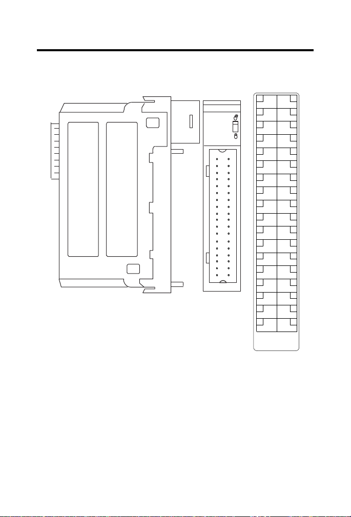
Figure 1 1756-M02AE Module
Side view
2 Axis Servo
Front view
1756-M02AE module
2
4
6
8
10
12
14
16
18
20
22
24
26
28
30
32
34
36
1
3
5
7
9
11
13
15
17
19
21
23
25
27
29
31
33
35
+OUT-0
-OUT-0
+ENABLE-0
-ENABLE-0
DRVFLT-0
CHASSIS
IN_COM
HOME-0
REG24V-0
REG5V-0
+OK
CHASSIS
+CHA-0
-CHA-0
+CHB-0
-CHB-0
+CHZ-0
-CHZ-0
+OUT-1
-OUT-1
+ENABLE-1
-ENABLE-1
DRVFLT-1
CHASSIS
IN_COM
HOME-1
REG24V-1
REG5V-1
-OK
CHASSIS
+CHA-1
-CHA-1
+CHB-1
-CHB-1
+CHZ-1
-CHZ-1
1756-MO2AE
2 AXIS
ENCODER/ANALOG
SERVO
RTB door label
Analog Encoder (AE) Servo Module 5
If you did not receive these components, contact your local Allen-Bradley
representative.
Removable Terminal Block and Housing
A separately-ordered RTB connects field-side wiring to the module. You
cannot use your module without an RTB and its components.
Use one of the following RTBs with your module:
Publication 1756-IN047D-EN-P - March 2001
Page 6
6 Analog Encoder (AE) Servo Module
WARNING
!
• 1756-TBCH 36-position cage clamp RTB
• 1756-TBS6H 36-position spring clamp RTB
You received the following components with your RTB:
• 1756-TBH standard-depth RTB housing
• wedge-shaped keying tabs and U-shaped keying bands
• RTB door label
Installing the Module
When you remove or insert an RTB with field-side
power applied, unintended machine motion or loss of
process control can occur. Exercise extreme caution
when power is applied. Failure to observe this caution
can cause personal injury.
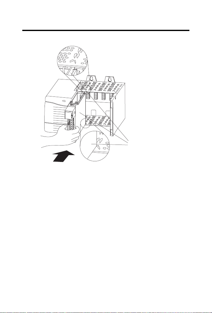
To install the AE module:
1. Align the module circuit board with the top and bottom chassis
guides.
Publication 1756-IN047D-EN-P - March 2001
Page 7
Analog Encoder (AE) Servo Module 7
P
O
W
E
R
Printed circuit board
Figure 2 Circuit Board Alignment
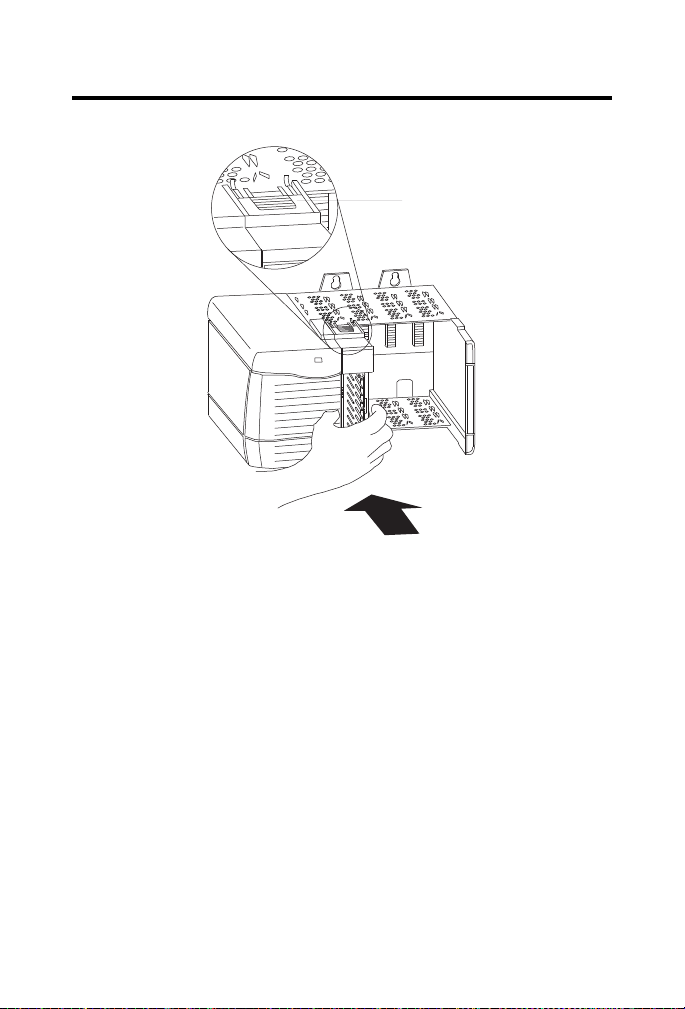
2. Push evenly and firmly to seat the module in the chassis. It is seated
when the top and bottom locking tabs have snapped into place.
Publication 1756-IN047D-EN-P - March 2001
Page 8
8 Analog Encoder (AE) Servo Module
P
O
W
E
R
Locking
tab
Figure 3 Module Locking Tabs
Note: The 1756 chassis provides grounding for your module.
Keying the Removable Terminal Block
To identify the RTB that belongs with each module, you can use a module
keying pattern. First, you can create a unique keying pattern for your module
using the U-shaped keying bands that you received with your RTB. Then you
can use the keying tabs to key the RTB with the same pattern as the module.
To prevent confusion, use a unique keying pattern to each module.
To key the module:
1. Insert the U-shaped keying band with the longer side near the
terminals.
Publication 1756-IN047D-EN-P - March 2001
Page 9
Analog Encoder (AE) Servo Module 9
P
OWER
U-shaped
keying band
Figure 4 Keying Band
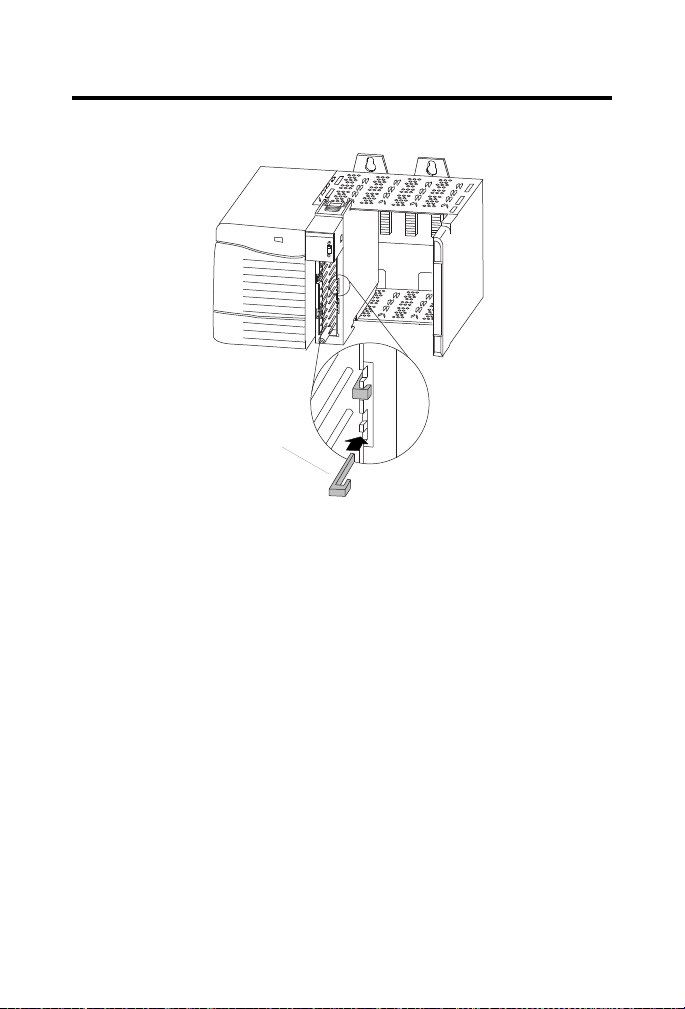
2. Push the keying band onto the module until it snaps into place.
To key your removable terminal block:
1. With the rounded edge first, insert the wedge-shaped keying tab on
the RTB.
Note: Insert the wedge-shaped keying tabs in positions that
correspond to unkeyed positions on the module
Publication 1756-IN047D-EN-P - March 2001
Page 10
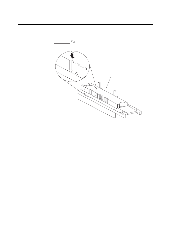
10 Analog Encoder (AE) Servo Module
Wedge-shaped
keying tab
Bottom of RTB
Figure 5 Keying Tab.
2. Push the keying tab onto the RTB until it stops.
Note: To use the RTB in future module applications, you can reposition
the keying tabs on the RTB.
Wiring a Removable Terminal Block
There are two types of RTBs:
This section describes how to wire each type of RTB and shows wiring
examples for the AE module.
Wire the RTB before installing it onto the module. Use a 1/8 inch (3.2mm)
maximum flat-bladed screwdriver.
Publication 1756-IN047D-EN-P - March 2001
• spring clamp
• cage clamp
Page 11
Analog Encoder (AE) Servo Module 11
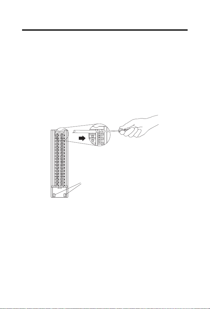
Strain Relief Area
Wiring a Spring Clamp RTB
To wire a spring clamp RTB:
1. Strip a maximum of 7/16 inch (11mm) of insulation from the end of
your wire.
2. Insert the screwdriver into the outer hole of the RTB.
3. Insert the wire into the open terminal and remove the screwdriver.
Figure 6 Strain Relief Area
4. After you complete field-side wiring, secure the wires in the strain
relief area with a cable-tie.
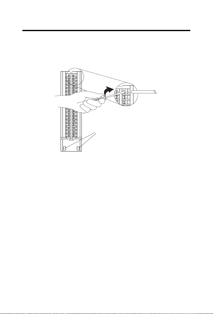
Wiring a Cage Clamp RTB
To wire a cage clamp RTB:
1. Strip 5/16 - 3/8 inch (8 - 9.5mm) of insulation from the end of your
wire.
2. Insert the screwdriver into the open terminal.
Publication 1756-IN047D-EN-P - March 2001
Page 12
12 Analog Encoder (AE) Servo Module
Strain Relief Area
3. Turn the screw clockwise to close the terminal on the wire. Use
5 lb-in. (0.5 Nm) maximum torque
Figure 7 Closing Wire Terminal.
4. After you complete field-side wiring, secure the wires in the strain
relief area with a cable-tie.
Publication 1756-IN047D-EN-P - March 2001
Page 13

General Cable
C0720
To servo drive
To servo drive
To home
limit switch
To registration
sensor
To encoder
To E-stop relay coil
General Cable
C0720
General Cable
C0720
General Cable
C0720
General Cable
C0722
General Cable
C0721
2
4
6
8
10
12
14
16
18
20
22
24
26
28
30
32
34
36
1
3
5
7
9
11
13
15
17
19
21
23
25
27
29
31
33
35
+OUT-0
-OUT-0
+ENABLE-0
-ENABLE-0
DRVFLT-0
CHASSIS
IN_COM
HOME-0
REG24V-0
REG5V-0
+OK
CHASSIS
+CHA-0
-CHA-0
+CHB-0
-CHB-0
+CHZ-0
-CHZ-0
-OK
+OUT-1
-OUT-1
+ENABLE-1
-ENABLE-1
DRVFLT-1
CHASSIS
IN_COM
HOME-1
REG24V-1
REG5V-1
CHASSIS
+CHA-1
-CHA-1
+CHB-1
-CHB-1
+CHZ-1
-CHZ-1
Analog Encoder (AE) Servo Module 13
Wiring Examples
Figure 8 Wiring to a servo module RTB
Note: This is a general wiring example illustrating Axis 1 wiring only.
Other configurations are possible with Axis 0 wiring identical to Axis 1.
Publication 1756-IN047D-EN-P - March 2001
Page 14

14 Analog Encoder (AE) Servo Module
5V DC
Field Power
Supply
+5V DC
+5 COM
RED
BLK
To fault
string
OK
RED
BLK
WHT
BLK
RED
BLK
WHT
BLK
RED
BLK
GRN
BLK
+OUT 0
-OUT 0
+ENABLE 0
-ENABLE 0
DRVFLT 0
CHASSIS
IN_COM
HOME 0
REG24V 0
REG5V 0
+OK
CHASSIS
+CHA 0
-CHA 0
+CHB 0
-CHB 0
+CHZ 0
-CHZ 0
+OUT 1
-OUT 1
+ENABLE 1
-ENABLE 1
DRVFLT 1
CHASSIS
IN_COM
HOME 1
REG24V 1
REG5V 1
-OK
CHASSIS
+CHA 1
-CHA 1
+CHB 1
-CHB 1
+CHZ 1
-CHZ 1
Servo Module RTB
1394CCAExx
24V DC
Field Power
Supply
1394 Servo Drive
1394CCAExx
WHT
BLK
RED
BLK
+ENABLE 1
-ENABLE 1
DRVFLT 1
IN_COM
TB2 7
TB2 19
TB2 18
W2
W1
TB2 15
24V DC
24V COM
24V DC
24V COM
24V ENABLE COM
A1 ENABLE
DROK
DROK
AQB1
A
RED OK+
BLK OK-
1756-M02AE
Axis 1
ENA/DR OK 1
ENC. PWR -1
A
Figure 9 Wiring to a 1394 Servo Drive (in Torque Mode only)
Note: The wiring diagram illustrates Axis 1 wiring only. Other
configurations are possible.
Note: The 1394CCAExx cable is wired to connect to torque command
reference input pins.
Note: An external +5V power supply is required to power the encoder
driver circuit of the 1394 servo drive. Because this connection is shared by all
four axis encoder driver circuits, only one connection is needed to the +5V
field supply.
Note: The xx in the cable number is the length of the cable. Options are
5, 10, 25, and 50 feet.
Publication 1756-IN047D-EN-P - March 2001
Page 15

Analog Encoder (AE) Servo Module 15
Individually Jacketed Pairs
7
1216
ENABLE/DRIVE FAULT - AXIS 0
5.0 in.
1.0 in.
5V ENC PWR - AXIS 0
M02AE - OK
AXIS 0
1394-CFLAE
1756-M02AE
3.0 in.
Figure 10 The 1394-CFLAExx Cable Wiring Diagram
Note: The 1394-CFLAE cable is available in 1, 3, 8, and 15 meter lengths.
Publication 1756-IN047D-EN-P - March 2001
Page 16

16 Analog Encoder (AE) Servo Module
3
9
+5V
+5VCOM
4
10
5
11
6
12
CHANNEL A HIGH
CHANNEL A LOW
CHANNEL B HIGH
CHANNEL B LOW
CHANNEL Z HIGH
CHANNEL Z LOW
VREF+
TREF+
VREFTREF-
1
2
7
8
(DROK-0)
(24V EN COM)
(24V)
(AX_-ENABLE)
TO SYSTEM
FAULT STRING
RED 22GA
BLACK 22GA
DRAIN
ORANGE 22GA
WHT/ORG 22GA
YELLOW 22GA
WHT/YEL 22GA
GREEN 22GA
WHT/GRN 22GA
DRAIN
BLUE 22GA
WHT/BLU 22GA
DRAIN
VIOLET 22GA
WHT/VIO 22GA
GRAY 22GA
WHT/GRY 22GA
DRAIN
RED 22GA
BLACK 22GA
DRAIN
Figure 11 Pinouts for the 1394-CFLAE
Publication 1756-IN047D-EN-P - March 2001
Page 17

Analog Encoder (AE) Servo Module 17
24 VDC
Field Power Supply
24VDC
READY+
24VCOM
COMMAND+
COMMAND-
ENABLE
READY-
AOUT+
AOUTBOUT+
BOUTIOUT+
IOUT-
24VDC
24VCOM
24 VDC
24 VCOM
+OUT
-OUT
+ENABLE
-ENABLE
DRVFLT
IN_COM
+CHA
-CHA
+CHB
-CHB
+CHZ
-CHZ
J1-5
J1-26
J1-24
J1-6
J1-13
J1-22
J1-23
J1-20
J1-25
J1-7
J1-8
J1-9
J1-10
J1-11
J1-12
General Cable
C0720
General Cable
C0721
General Cable
C0722
From
1756-M02AE
From
1756-M02AE
From
1756-M02AE
J1 to 50-pin
Terminal Block
(Kit P/N 9109-1391)
Ultra 100 Series
Digital Servo Drive
Interface
Cable
P/N 9109-1369-003
J1
Figure 12 Wiring to an Ultra 100 Series Drive
Note: This is a general wiring example only. Other configurations are
possible. For more information, refer to the Ultra 100 Series Installation Manual,
publication number 1398-5.2.
Publication 1756-IN047D-EN-P - March 2001
Page 18

18 Analog Encoder (AE) Servo Module
J1 to 50-pin
Terminal Block
(Kit P/N 9109-1391)
24VDC
READY+
24VCOM
COMMAND+
COMMAND-
ENABLE
READY-
AOUT+
AOUTBOUT+
BOUTIOUT+
IOUT-
+OUT
-OUT
+ENABLE
-ENABLE
DRVFLT
IN_COM
+CHA
-CHA
+CHB
-CHB
+CHZ
-CHZ
J1-5
J1-24
J1-6 or 13
J1-22
J1-23
J1-20
J1-25
J1-7
J1-8
J1-9
J1-10
J1-11
J1-12
General Cable
C0720
General Cable
C0721
General Cable
C0722
From
1756-M02AE
From
1756-M02AE
From
1756-M02AE
Ultra 200 Series
Digital Servo Drive
Interface
Cable
P/N 9109-1369-003
J1
24V
BRAKE
RESET
Individually Jacketed pairs
1398-CFLAE
J1
1.0 in.
5.0 in.
Figure 13 Wiring to an Ultra 200 Series Drive
Note: This is a general wiring example only. Other configurations are
possible. For more information, refer to the Ultra 200 Series Installation Manual,
publication number 1398-5.0.
Figure 14 1398-CFLAExx Cable Diagram
Note: The 1398-CFLAE Cable is available in 10, 25, and 50 foot lengths.
Publication 1756-IN047D-EN-P - March 2001
Page 19

Analog Encoder (AE) Servo Module 19
WHT/ORG 22GA
WHT/YEL 22GA
DRAIN
TAN 28GA
DRAIN
WHT/RED 22GA
WHT/BLK 22GA
DRAIN
WHT/GRN 22GA
WHT/BLU 22GA
DRAIN
BROWN 28GA
RED 28GA
ORANGE 28GA
YELLOW 28GA
DRAIN
GREEN 28GA
BLUE 28GA
VIOLET 28GA
GRAY 28GA
WHITE 28GA
BLACK 28G
DRAIN
49
50
21
5
6
22
23
26
24
20
25
13
7
8
9
10
11
12
BRAKE +
BRAKE -
RESET
24VDC
24VCOM
COMMAND +
COMMAND -
24VDC
READY +
ENABLE
READY 24VCOM
AOUT +
AOUT BOUT +
BOUT IOUT +
IOUT -
Wires
Terminated
with
Ferrules
Wires
Stripped
Back
.25 in.
Figure 15 Pinouts for1398-CFLAExx Cable
Publication 1756-IN047D-EN-P - March 2001
Page 20

20 Analog Encoder (AE) Servo Module
24 VDC
Field Power
Supply
REG24V
IN_COM
General Cable
C0720
From
1756-M02AE
+-
24 Volt
Sourcing Type
Registration
Sensor
Supply
Output
Common
5 VDC
Field Power
Supply
REG5V
IN_COM
General Cable
C0720
From
1756-M02AE
+-
5 Volt
Sourcing Type
Registration
Sensor
Supply
Output
Common
Wiring Registration Sensors
The registration inputs to the servo module can support 24V or 5V
registration sensors. These inputs must be wired to receive source current
from the sensor. Only use sourcing type registration sensors. Current sinking
sensor configurations are not allowed because the registration input common
(IN_COM) is shared with the other 24V servo module inputs.
Figure 16 24V Registration Sensor
Figure 17 5V Registration Sensor
Publication 1756-IN047D-EN-P - March 2001
Page 21

Analog Encoder (AE) Servo Module 21
24 VDC
Field Power
Supply
HOME
IN_COM
General Cable
C0720
From 1756-M02AE
+-
Wiring the Home Limit Switch Input
The home limit switch inputs to the servo module are designed for 24V
nominal operation. These inputs should be wired for current sourcing
operation.
Figure 18 Home Limit Switch
Wiring the OK Contacts
A set of isolated solid-state OK relay contacts is provided for optional
interface to an E-stop string, which controls power to the associated drives.
The OK contacts are rated for pilot duty and can drive an external 24V relay
(for example, Allen-Bradley 700-HA32Z24) whose contacts can be
incorporated into the E-Stop string as shown below.
Publication 1756-IN047D-EN-P - March 2001
Page 22

22 Analog Encoder (AE) Servo Module
IMPORTANT
24 VDC
Field Power
Supply
+OK
-OK
General Cable
C0720
From 1756-M02AE
+-
OK Relay
OK Relay
Contacts
Start
CR1
Stop
CR1
CR1
M1
+
-
24 VDC
Field Power
Supply
To User's circuitry
+OK -OK
Figure 19 OK Relay Pilot Duty Application Wiring
When the OK Relay is loaded with an inductive load,
use a counter-EMF suppression diode across the load.
The maximum rating of the OK relay contacts must not
exceed 60V DC.
Assembling the Removable Terminal Block and Housing
To assemble the removable terminal block and housing:
Publication 1756-IN047D-EN-P - March 2001
1. Align the grooves at the bottom of each side of the housing with the
side edges of the RTB.
2. Slide the RTB into the housing until it snaps into place
Page 23

Analog Encoder (AE) Servo Module 23
WARNING
!
WARNING
!
Groove
Side edge of RTB
Strain relief area
Groove
Side edge of RTB
1756-TBCH RTB shown for reference
Figure 20 RTB and Housing.
Installing the Removable Terminal Block onto the Module
A shock hazard exists. If the RTB is installed onto the
module while the field-side power is applied, the RTB is
electrically live. Do not touch the RTB terminals. Failure
to observe this caution can cause personal injury.
When you connect or disconnect the RTB with field
side power applied, an electrical arc can occur. This
could cause an explosion in hazardous location
installations. Be sure that all sources of power are
removed or the area is nonhazardous before proceeding.
Before installing the RTB, make certain:
Publication 1756-IN047D-EN-P - March 2001
Page 24

24 Analog Encoder (AE) Servo Module
P
O
W
E
R
Top
guide
Bottom
guide
Left side
guides
• field-side wiring of the RTB has been completed.
• the RTB housing is snapped into place on the RTB.
• the RTB housing door is closed.
• the locking tab at the top of the module is unlocked.
To install the removable terminal block onto the module:
1. Align the top, bottom, and left side guides of the RTB with the guides
on the module.
Figure 21 Aligning RTB
2. Press quickly and evenly to seat the RTB on the module until the
latches snap into place.
3. Slide the locking tab down to lock the RTB onto the module.
Publication 1756-IN047D-EN-P - March 2001
Page 25

Analog Encoder (AE) Servo Module 25
P
OW
E
R
Locking
tab
Figure 22 Locking Tabs
Checking the LED Indicators
The module provides bi-colored LED indicators to show individual drive and
feedback status for both axes and a single bi-colored LED for module OK.
Publication 1756-IN047D-EN-P - March 2001
Page 26

26 Analog Encoder (AE) Servo Module
CH 0 CH 1
FDBK
DRIVE
OK
2 AXIS SERVO
FDBK
DRIVE
Figure 23 1756-M02AE Module LEDs
During power up, the module completes an indicator test. The OK indicator
turns red for 1 second and then turns to flashing green if the module passes
all its self tests.
This completes the installation of the module.
Understanding Module Status Using the OK Indicator
If the OK LED
displays:
Off The module is not operating. • Apply chassis power.
Then the module status
is:
Take this action:
• Verify the module is completely
inserted into the chassis and
backplane.
Flashing green
light
The module has passed
internal diagnostics, but it is
not communicating axis
data over the backplane.
• None, if you have not
configured the module.
• If you have configured the
module, check the slot number
in the 1756-M02AE Properties
dialog box.
Publication 1756-IN047D-EN-P - March 2001
Page 27

Analog Encoder (AE) Servo Module 27
If the OK LED
displays:
Steady green
light
Flashing red
light
Solid red light • A potential
Then the module status
is:
• Axis data is being
exchanged with
the module.
• The module us in
the normal
operating state.
• A major
recoverable failure
has occurred.
• A communication
fault, timer fault,
or NVS update is
in progress.
• The OK contact
has opened.
nonrecoverable
fault has occurred.
• The OK contact
has opened.
Take this action:
None. The module is ready for action.
If an NVS update is in progress,
complete the NVS update.
If an NVS update is not in progress:
• Check the Servo Fault word for
the source of the error.
• Clear the servo fault condition
using the Motion Axis Fault
Reset instruction.
• Resume normal operation.
• If the flashing persists,
reconfigure the module.
• Reboot the module.
• If the solid red persists, replace
the module.
Understanding Module Status Using the FDBK Indicator
If the FDBK
LED displays:
Off The axis is not used. • None, if you are not using this
Flashing green
light
Then the module status
is:
The axis is in the normal
servo loop inactive state.
Take this action:
axis.
• If you are using this axis, make
sure the module is configured
and an axis tag has been
associated with the module.
None. The servo axis state can be
changed by executing motion
instructions.
Publication 1756-IN047D-EN-P - March 2001
Page 28

28 Analog Encoder (AE) Servo Module
If the FDBK
LED displays:
Steady green
light
Flashing red
light
Solid red light An axis encoder feedback
Then the module status
is:
The axis is in the normal
servo loop active state.
The axis servo loop error
tolerance has been
exceeded.
fault has occurred.
Take this action:
None. The servo can may be changed by
executing motion instructions.
• Correct the source of the
problem.
• Clear the servo fault condition
using the Motion Axis Fault
Reset instruction.
• Resume normal operation.
• Correct the source of the
problem by checking the
encoder and power
connections.
• Clear the servo fault condition
using the Motion Axis Fault
Reset instruction.
• Resume normal operation.
Understanding Module Status Using the DRIVE Indicator
If the DRIVE
LED displays:
Off • The axis is not
Flashing green
light
Then the module status
is:
used.
• The axis is a
position-only axis
type.
The axis drive is in the
normal disabled state.
Take this action:
• None, if the axis is not used or
is a position-only type.
• Otherwise, make sure the
module is configured, an axis
tag has been associated with
the module, and the axis type is
servo.
None. The servo axis state can be
changed by executing motion
instructions.
Publication 1756-IN047D-EN-P - March 2001
Page 29

Analog Encoder (AE) Servo Module 29
WARNING
!
If the DRIVE
LED displays:
Steady green
light
Flashing red
light
Solid red light The axis drive is faulted. • Check the drive status.
Then the module status
is:
The axis drive is in the
normal enabled state.
The axis drive output is in
the shutdown state.
Take this action:
None. The servo axis state can be
changed by executing motion
instructions.
• Check for faults that may have
generated this state.
• Execute the Shutdown Reset
motion instruction.
• Resume normal operation.
• Clear the Drive Fault condition
at the drive.
• Clear the servo fault condition
using the Motion Axis Fault
Reset instruction.
• Resume normal operation.
• Check the configuration for the
Drive Fault.
- If configured to be normally
open and there is no voltage,
this is the normal condition.
- If configured to be normally
closed and 24V is applied,
this is the normal condition.
Removing the Removable Terminal Block from the Module
A shock hazard exists. If the RTB is removed from the
module while the field-side power is applied, the module
is electrically live. Do not touch the RTBs terminals.
Failure to observe this caution can cause personal injury.
Publication 1756-IN047D-EN-P - March 2001
Page 30

30 Analog Encoder (AE) Servo Module
WARNING
!
P
OW
E
R
P
U
L
L
H
E
R
E
D
A
N
G
E
R
P
U
L
L
H
E
R
E
D
A
N
G
E
R
When you connect or disconnect the RTB with field
side power applied, an electrical arc can occur. This
could cause an explosion in hazardous location
installations. Be sure that all sources of power are
removed or the area is nonhazardous before proceeding.
You must remove the RTB before you can remove the module.
To remove the RTB from the module:
1. Unlock the locking tab at the top of the module.
2. Open the RTB door using the bottom tab.
3. Hold the spot marked PULL HERE and pull the RTB toward you and
off the module.
Figure 24 Removing RTB
Publication 1756-IN047D-EN-P - March 2001
Page 31

Analog Encoder (AE) Servo Module 31
PO
W
ER
Removing the Module from the Chassis
To remove the module from the chassis:
1. If the RTB is on the module, unlock the RTB and remove it. For
more information, refer to Removing the Removable Terminal Block from the
Module.
2. Push in and hold the top and bottom locking tabs on the module.
Figure 25 Hold Locking Tabs
3. Pull the module out of the chassis.
Publication 1756-IN047D-EN-P - March 2001
Page 32

32 Analog Encoder (AE) Servo Module
PO
WE
R
Figure 26 Pulling Module Out
Module Specifications
Number of axes 2 axes maximum
Servo loop
Typ e
Gain resolution
Absolute position range
Rate
Module location 1756 ControlLogix chassis
Module keying Electronic
Power dissipation 5.5W maximum
Backplane current 5.1V dc @ 700 mA and 24V dc @ 2.5 mA
Encoder input
Typ e
Mode
Rate
Electrical interface
Voltage range
On state
Off state
Input impedance
Nested PI digital position and velocity servo
32-bit floating point
±1,000,000,000 encoder counts
5 kHz
Incremental AB quadrature with marker
4X quadrature
4 MHz counts per second maximum
Optically isolated 5V differential
3.4V to 5.0V
0V to 1.8V
531 Ohms differential
Publication 1756-IN047D-EN-P - March 2001
Page 33

Analog Encoder (AE) Servo Module 33
Registration inputs
Typ e
24V input voltage
Maximum
Minimum on
Maximum off
5V input voltage
Maximum
Minimum on
Maximum off
Input impedance
24V input
5V input
Response time
(position latched)
All other inputs
Typ e
Input voltage
Maximum
Minimum on
Maximum off
Input impedance
Servo output
Typ e
Isolation
Voltage range
Voltage resolution
Load
Maximum offset
Gain error
Optically isolated, current sinking input
+24V dc nominal
26.4V
18.5V
3.5V
+5V dc nominal
5.5V
3.7V
1.5V
9.5 kOhms
1.2 kOhms
1µs
Optically isolated, current sinking input
+24V dc nominal
26.4V
17.0V
8.5V
7.5 kOhms
Analog voltage
200 kOhms
±10V
16 bits
5.6 kOhms resistive minimum
25 mV
±4%
All other outputs
Typ e
Operating voltage
Maximum
Operating current
Solid-state isolated relay contacts
+24V dc nominal (Class 2 source)
26.4V
75 mA
RTB keying User-defined
Field wiring arm
36-position RTB (1756-TBCH or -TBS6H)
RTB screw torque (cage clamp) 5 lb-in. (0.5 Nm) maximum
Conductors
Wire size
Category
22 AWG to 14 AWG copper
3/64 inch (1.2 mm) insulation maximum
2,3
1
Screwdriver blade width for RTB 1/8 inch (3.2 mm) maximum
1
1
Publication 1756-IN047D-EN-P - March 2001
Page 34

34 Analog Encoder (AE) Servo Module
N223
Environmental conditions
Operating temperature
Storage temperature
Relative humidity
Agency Certifications
When product is marked
1) Maximum wire size will require the extended depth RTB housing (1756-TBE).
2) Use this conductor category information for planning conductor routing as described in the system
level installation manual.
3) Refer to Industrial Automation Wiring and Grounding Guidelines, publication number 1770-4.1.
0 to 60ºC (32 to 140ºF)
-40 to 85ºC (-40 to 185ºF)
5 to 95% noncondensing
Listed Industrial Control Equipment
Certified Process Control Equipment
Certified Class I, Division 2, Group A, B, C, D
Marked for applicable directives
Marked for all applicable acts
Installation Environment
This product must be mounted within a suitable system enclosure to prevent
personal injury resulting from accessibility to live parts. The interior of this
enclosure must be accessible only by the use of a tool.
This industrial control equipment is intended to operate in a Pollution Degree
2 environment, in overvoltage category II applications, (as defined in IEC
publication 664A) at altitudes up to 2000 meters without derating.
The following information applies when operating this equipment in hazardous locations:
Products marked “CL I, DIV 2, GP A, B, C, D” are suitable for use in Class I
Division 2 Groups A, B, C, D, Hazardous Locations and nonhazardous
locations only. Each product is supplied with markings on the rating
nameplate indicating the hazardous location temperature code. When
combining products within a system, the most adverse temperature code
(lowest “T” number) may be used to help determine the overall temperature
Publication 1756-IN047D-EN-P - March 2001
Page 35

Analog Encoder (AE) Servo Module 35
WARNING
!
code of the system. Combinations of equipment in your system are subject to
investigation by the local Authority Having Jurisdiction at the time of
installation.
EXPLOSION HAZARD –
• Do not disconnect equipment unless power has
been removed or the area is known to be
nonhazardous.
• Do not disconnect connections to this equipment
unless power has been removed or the area is
known to be nonhazardous. Secure any external
connections that mate to this equipment by using
screws, sliding latches, threaded connectors, or
other means provided with this product.
• Substitution of components may impair suitability
for Class I, Division 2.
• If this product contains batteries, they must only be
changed in an area known to be nonhazardous.
Informations sur l’utilisation de cet équipement
en environnements dangereux:
Les produits marqués «CL I, DIV 2, GP A, B, C, D» ne conviennent qu’à une
utilisation en environnements de Classe I Division 2 Groupes A, B, C, D
dangereux et non dangereux. Chaque produit est livré avec des marquages sur
sa plaque d’identification qui indiquent le code de température pour les
environnements dangereux. Lorsque plusieurs produits sont combinés dans
un système, le code de température le plus défavorable (code de température
le plus faible) peut être utilisé pour déterminer le code de température global
du système. Les combinaisons d’équipements dans le système sont sujettes à
inspection par les autorités locales qualifiées au moment de l’installation.
Publication 1756-IN047D-EN-P - March 2001
Page 36

36 Analog Encoder (AE) Servo Module
Informations sur l’utilisation de cet équipement
en environnements dangereux:
RISQUE D’EXPLOSION –
• Couper le courant ou s’assurer que l’environnement
est classé non dangereux avant de débrancher
l'équipement.
• Couper le courant ou s'assurer que l’environnement
est classé non dangereux avant de débrancher les
connecteurs. Fixer tous les connecteurs externes
reliés à cet équipement à l'aide de vis, loquets
coulissants, connecteurs filetés ou autres moyens
fournis avec ce produit.
• La substitution de composants peut rendre cet
équipement inadapté à une utilisation en
environnement de Classe 1, Division 2.
• S’assurer que l’environnement est classé non
dangereux avant de changer les piles.
Publication 1756-IN047D-EN-P - March 2001
Page 37

NOTES:
Analog Encoder (AE) Servo Module 37
Publication 1756-IN047D-EN-P - March 2001
Page 38

38 Analog Encoder (AE) Servo Module
NOTES:
Publication 1756-IN047D-EN-P - March 2001
Page 39

NOTES:
Analog Encoder (AE) Servo Module 39
Publication 1756-IN047D-EN-P - March 2001
Page 40

ControlLogix is a trademark of Allen-Bradley Company, Inc., a Rockwell
International company.
Publication 1756-IN047D-EN-P - March 2001 PN957536-48
Supersedes Publication 1 756-IN047C-EN-P - November 2000 © 2001 Rockwell International Corporation. Printed in USA
 Loading...