

Rockwell Automation 1756-L1M2, 1756-L55, 1756-L55M12, 1756-L55M14, 1756-L55M13 Installation Instructions Manual
...
Installation Instructions
ControlLogix Controller and Memory Board
Catalog Numbers 1756-L1, 1756-L1M1, 1756-L1M2,
1756-L1M3, 1756-L55, 1756-L55M12, 1756-L55M13,
1756-L55M14, 1756-L55M16, 1756-L55M22,
1756-L55M23, 1756-L55M24, 1756-L61, 1756-L62,
1756-L63, 1756-L64, 1756-L65, 1756-M1, 1756-M2,
1756-M3, 1756-M12, 1756-M13, 1756-M14,
1756-M16, 1756-M22, 1756-M23, 1756-M24,
1784-CF64, 1784-CF128
Topic Page
Important User Information 3
Explosion Hazards 4
Preventing Electrostatic Discharge 4
Removing Module While Under Power (RIUP) 4
Environment and Enclosure 5
North American Hazardous Location Approval 6
European Hazardous Location Approval 7
Before You Begin 8
Replace a Suspected Failed Controller 9
Resolving Common Errors 11
2 ControlLogix Controller and Memory Board
Publication
1756-IN101L-EN-P - June 2008
Required System Components 12
Firmware Revisions 14
Preparing the Chassis 16
Remove the Controller from the Chassis 16
Installing a Memory Board on a ControlLogix5550 or ControlLogix5555 Controller
17
Installing a CompactFlash Card in a Controller 22
Connecting a Battery 25
Installing the Controller into the Chassis 28
Check the BAT Status Indicator 29
Checking the OK Status Indicator 30
Update the Controller 32
Connecting a Serial Cable 34
Interpreting the Status Indicators 36
Clear a Major Fault 38
Clear a Nonrecoverable Fault 39
Choosing the Operating Mode of the Controllers 40
Specifications 41
Topic Page
ControlLogix Controller and Memory Board 3
Publication
1756-IN101L-EN-P - June 2008
Important User Information
Solid state equipment has operational characteristics differing from those of electromechanical
equipment. Safety Guidelines for the Application, Installation and Maintenance of Solid State Controls
(Publication SGI-1.1
available from your local Rockwell Automation sales office or online at
http://literature.rockwellautomation.com
) describes some important differences between solid state
equipment and hard-wired electromechanical devices. Because of this difference, and also because of
the wide variety of uses for solid state equipment, all persons responsible for applying this equipment
must satisfy themselves that each intended application of this equipment is acceptable.
In no event will Rockwell Automation, Inc. be responsible or liable for indirect or consequential damages
resulting from the use or application of this equipment.
The examples and diagrams in this manual are included solely for illustrative purposes. Because of the
many variables and requirements associated with any particular installation, Rockwell Automation, Inc.
cannot assume responsibility or liability for actual use based on the examples and diagrams.
No patent liability is assumed by Rockwell Automation, Inc. with respect to use of information, circuits,
equipment, or software described in this manual.
Reproduction of the contents of this manual, in whole or in part, without written permission of Rockwell
Automation, Inc., is prohibited.
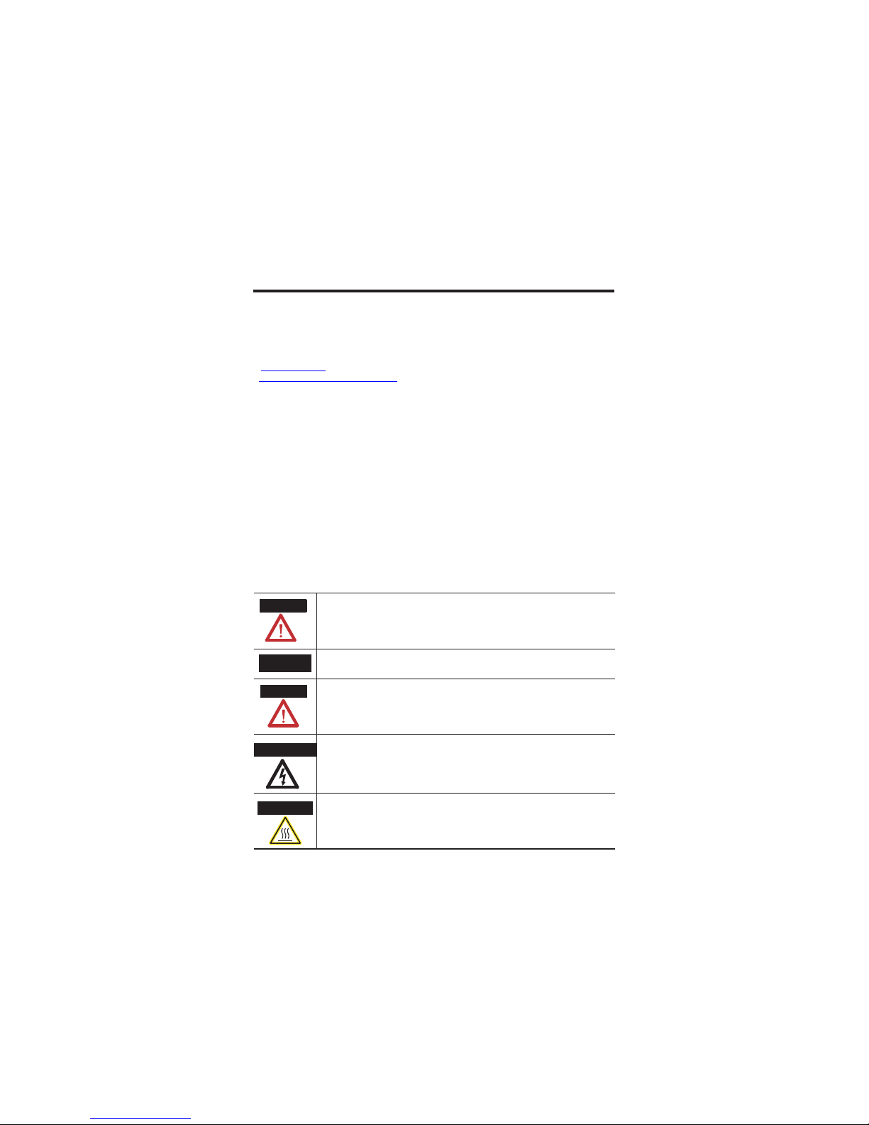
Throughout this manual, when necessary, we use notes to make you aware of safety considerations.
WARNING
Identifies information about practices or circumstances that can cause an explosion in
a hazardous environment, which may lead to personal injury or death, property
damage, or economic loss.
IMPORTANT
Identifies information that is critical for successful application and understanding of
the product.
ATTENTION
Identifies information about practices or circumstances that can lead to personal
injury or death, property damage, or economic loss. Attentions help you identify a
hazard, avoid a hazard and recognize the consequences.
Labels may be on or inside the equipment (for example, a drive or motor) to alert
people that dangerous voltage may be present.
Labels may be on or inside the equipment (for example, a drive or motor) to alert
people that surfaces may reach dangerous temperatures.
SHOCK HAZARD
BURN HAZARD
4 ControlLogix Controller and Memory Board
Publication
1756-IN101L-EN-P - June 2008
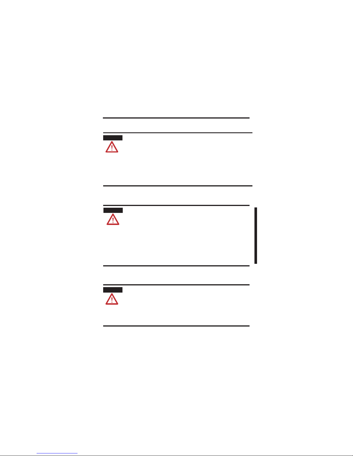
Explosion Hazards
Preventing Electrostatic Discharge
Removing Module While Under Power (RIUP)
WARNING
An electrical arc can occur if you:
x insert or remove the CompactFlash card.
x insert or remove the controller while backplane power is on.
x connect or disconnect the battery.
x connect or disconnect the serial cable with power applied to this module
or the serial device on the other end of the cable.
This could cause an explosion in hazardous location installations. Make sure
that power is removed or the area is nonhazardous before proceeding
ATTENTION
This equipment is sensitive to electrostatic discharge, which can cause
internal damage and affect normal operation. Follow these guidelines when
you handle this equipment.
x Touch a grounded object to discharge potential static.
x Wear an approved grounding wriststrap.
x Do not touch connectors or pins on component boards.
x Do not touch circuit components inside the equipment.
x Use a static-safe workstation, if available.
x Store the equipment in appropriate static-safe packaging when not in
use.
WARNING
When you insert or remove the module while backplane power is on, an
electrical arc can occur. This could cause an explosion in hazardous location
installations.
Be sure that power is removed or the area is nonhazardous before
proceeding. Repeated electrical arcing causes excessive wear to contacts on
both the module and its mating connector. Worn contacts may create
electrical resistance that can affect module operation.
ControlLogix Controller and Memory Board 5
Publication
1756-IN101L-EN-P - June 2008
Environment and Enclosure
ATTENTION
This equipment is intended for use in a Pollution Degree 2 industrial
environment, in overvoltage Category II applications (as defined in IEC
publication 60664-1), at altitudes up to 2000 m (6561 ft) without
derating.
This equipment is considered Group 1, Class A industrial equipment
according to IEC/CISPR Publication 11. Without appropriate
precautions, there may be potential difficulties ensuring
electromagnetic compatibility in other environments due to
conducted as well as radiated disturbance.
This equipment is supplied as open-type equipment. It must be
mounted within an enclosure that is suitably designed for those
specific environmental conditions that will be present and
appropriately designed to prevent personal injury resulting from
accessibility to live parts. The enclosure must have suitable
flame-retardant properties t o prevent or minimize the spread of flame,
complying with a flame spread rating of 5VA, V2, V1, V0 (or
equivalent) if non-metallic. The interior of the enclosure must be
accessible only by the use of a tool. Subsequent sections of this
publication may contain additional information regarding specific
enclosure type ratings that are required to comply with certain
product safety certifications.
In addition to this publication, see:
x Industrial Automation Wiring and Grounding Guidelines, for additional
installation requirements, Allen-Bradley publication 1770-4.1
.
x NEMA Standards publication 250 and IEC publication 60529, as
applicable, for explanations of the degrees of protection provided by
different types of enclosure.
6 ControlLogix Controller and Memory Board
Publication
1756-IN101L-EN-P - June 2008
North American Hazardous Location Approval
The following information applies when
operating this equipment in hazardous
locations.
Informations sur l’utilisation de cet
équipement en environnements dangereux.
Products marked "CL I, DIV 2, GP A, B, C, D" are suitable for
use in Class I Division 2 Groups A, B, C, D, Hazardous
Locations and nonhazardous locations only. Each product is
supplied with markings on the rating name plate indicating
the hazardous location temperature code. When
combining products within a system, the most adverse
temperature code (lowest "T" number) may be used to help
determine the overall temperature code of the system.
Combinations of equipment in your system are subject to
investigation by the local Authority H aving Jurisdiction at
the time of installation.
Les produits marqués "CL I, DIV 2, GP A, B, C, D" ne
conviennent qu'à une utilisation en environnements de
Classe I Division 2 Groupes A, B, C, D dangereux et non
dangereux. Chaque produit est livré avec des marquages sur
sa plaque d'identification qui ind iquent le code de
température pour les environnement s dangereux. Lorsque
plusieurs produits sont combinés dans un système, le code de
température le plus défavorable (code de t empérature le plus
faible) peut être utilisé pour déterminer le code de
température global du système. Les combinaisons
d'équipements dans le système sont sujettes à inspection par
les autorités locales qualifiées au moment de l'installation.
WARNING
EXPLOSION HAZARD -
• Do not disconnect equipme nt unless
power has been removed or the
area is known to be nonhazardous.
• Do not disconnect connections to
this equipment unless power has
been removed or the area is known
to be nonhazardous. Secure any
external connections that mate to
this equipment by using screws,
sliding latches, threaded
connectors, or other means
provided with this product.
• Substitution of components may
impair suitability for Class I,
Division 2.
• If this product contains batteries,
they must only be changed in an
area known to be nonhazardous.
AVERTISSEMENT
RISQUE D’EXPLOSION –
• Couper le courant ou s'assurer
que l'environnement est classé
non dangereux avant de
débrancher l'équipement.
• Couper le courant ou s'assurer
que l'environnement est classé
non dangereux avant de
débrancher les connecteurs. Fixer
tous les connecteurs externes
reliés à cet équipement à l'aide
de vis, loquets coulissants,
connecteurs filetés ou autres
moyens fournis avec ce produit.
• La substitution de composants
peut rendre cet équipement
inadapté à une utilisation en
environnement de Classe I,
Division 2.
• S'assurer que l'environnement est
classé non dangereux avant de
changer les piles.
ControlLogix Controller and Memory Board 7
Publication
1756-IN101L-EN-P - June 2008
European Hazardous Location Approval
European Zone 2 Certification (The following applies when the product bears the
Ex or EEx Marking)
This equipment is intended for use in potentially explosive atmospheres as defined by
European Union Directive 94/9/EC.
The LCIE (Laboratoire Central des Industries Electriques) certifies that this equipment has
been found to comply with the Essential Health and Safety Requirements relating to the
design and construction of Category 3 equipment intended for use in potentially explosive
atmospheres, given in Annex II to this Directive.
Compliance with the Essential Health and Safety Requirements has been assured by
compliance with EN 60079-15.
ATTENTION
This equipment is not resistant to sunlight or other sources of UV radiation.
WARNING
x This equipment must be used only with ATEX certified backplanes.
x Secure any external connections that mate to this equipment by using
screws, sliding latches, threaded connectors, or other means provided with
this product.
x Do not disconnect equipment unless power has been removed or the area is
known to be nonhazardous.
x Equipment must be installed in an enclosure providing at least IP54
protection when applied in Class I, Zone 2 environments.
x This equipment shall be used within its specified ratings defined by
Allen-Bradley.
8 ControlLogix Controller and Memory Board
Publication
1756-IN101L-EN-P - June 2008
Before You Begin
Read this section for important information about using these products,
noting that this publication covers the products shown in the table.
Product Cat. No. Series
ControlLogix5550 controller 1756-L1, 1756-L1M1, 1756-L1M2, 1756-L1M3 A
ControlLogix5555 controller 1756-L55, 1756-L55M12, 1756-L55M13,
1756-L55M14, 1756-L55M16, 1756-L55M22,
1756-L55M23, 1756-L55M24
A
ControlLogix5561 controller 1756-L61 A, B
ControlLogix5562 controller 1756-L62 A, B
ControlLogix5563 controller 1756-L63 A, B
ControllLogix5564 controller 1756-L64 B
ControlLogix5565 controller 1756-L65 B
ControlLogix5550 memory
board
1756-M1, 1756-M2, 1756-M3 A
ControlLogix5555 memory
board
1756-M12, 1756-M13, 1756-M14, 1756-M16,
1756-M22, 1756-M23, 1756-M24
A
Industrial CompactFlash
card
1784-CF64, 1784-CF128 A
ControlLogix Controller and Memory Board 9
Publication
1756-IN101L-EN-P - June 2008
Replace a Suspected Failed Controller
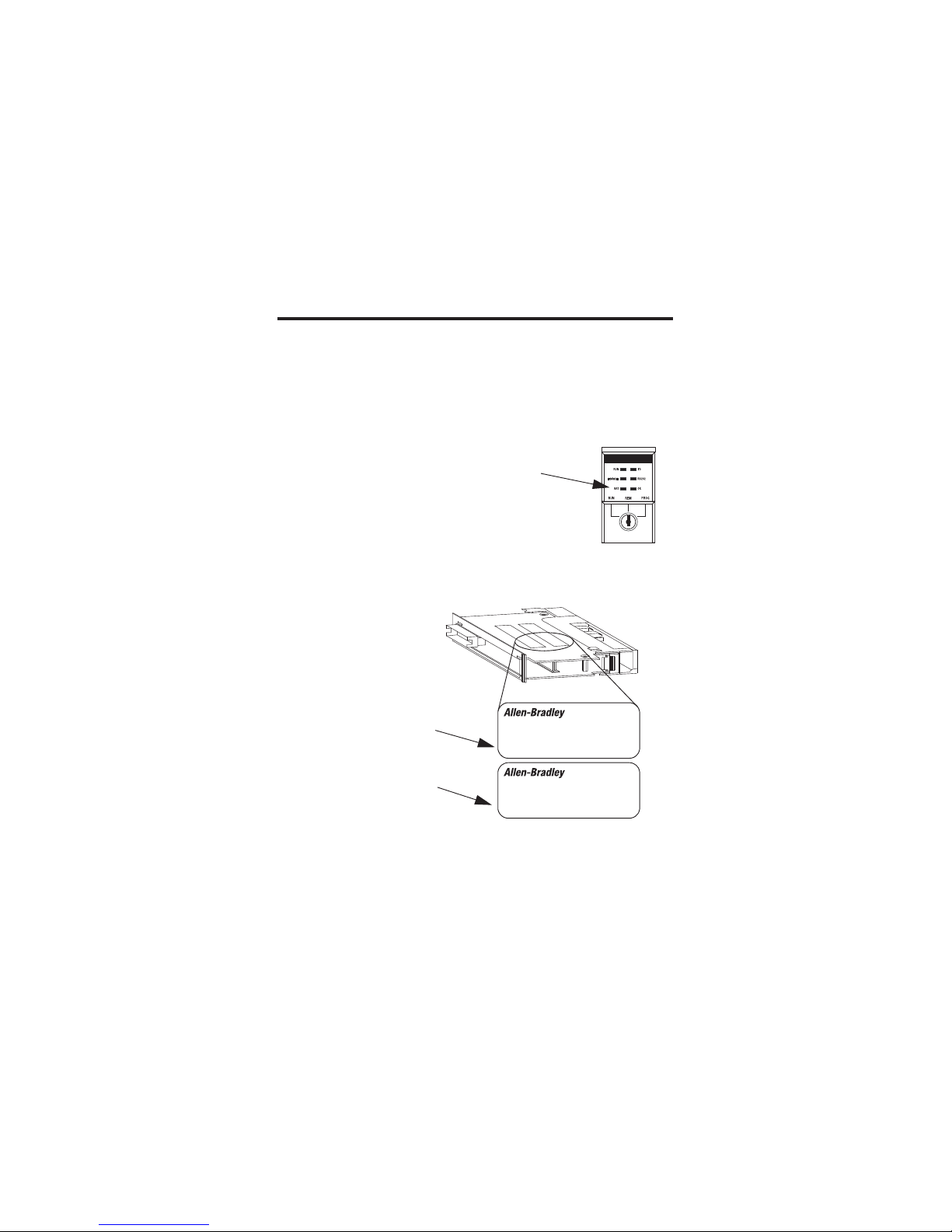
To replace a failed controller, do the following.
1. Cycle power to the chassis.
2. Make sure the OK status indicator is
solid red, noting that if the OK status
indicator is not solid red, the controller
does not require replacement.
3. Match the catalog numbers of the
controllers and memory boards, noting
that 1756-Mxxx is the catalog number of
the memory board, if one is installed, and
1756-Lxxx is the catalog number of the
controller, as shown in the figure.
ControlLogix
1756-M…
CAT. NO./SERIES
ControlLogix
1756-L…
CAT. NO./SERIES
1756-M...
1756-L...
10 ControlLogix Controller and Memory Board
Publication
1756-IN101L-EN-P - June 2008
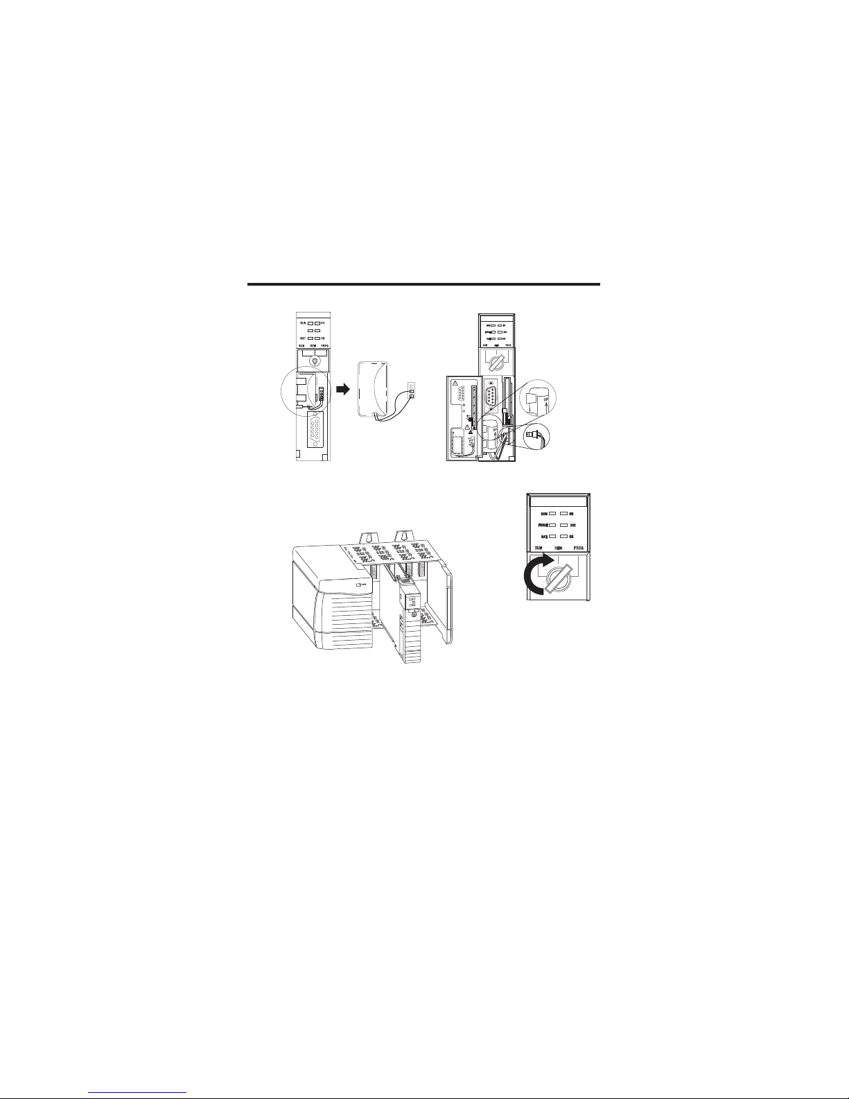
4. Insert the battery.
5. Insert the key, and turn it to the PROG position.
6. Insert the controller into the chassis.
7. Use ControlFlash software to update the firmware of the controller.
8. Download the RSLogix 5000 pro j ect to th e co ntroller.
RS232
BATTERY
PORT
1-DCD
2-RXD
4-DTR
3-TXD
5-GND
DSR-6
CTS-8
RTS-7
N/C-9
1
2
BATTERY
DATE
UP
COMPACT
FLASH
2
To
Insert 1
To Eject
1 + 2
2
1
1
42523
Series A
Series B
20880
ControlLogix Controller and Memory Board 11
Publication
1756-IN101L-EN-P - June 2008
Resolving Common Errors
To resolve common errors, see the following table. For more information on
how to avoid these commo n errors, refer to the Memory Board table or
Firmware Revisions
section.
IMPORTANT
Before you change a memory board, update the controller to a revision that
is compatible with the memory board that you intend to install.
Make sure you use the correct firmware revision.
Common Errors
Controller Be sure that you
All Update the firmware of the controller to the revision that
is compatible with your RSLogix 5000 software.
Controllers ship with firmware that lets you only update
them.
ControlLogix5550 Use the correct memory board (one per controller).
ControlLogix5555 x If you purchased a ControlLogix5555 controller
without a memory board, you must install a
memory board.
x Use the correct memory board (one per
controller).
x Use the correct firmware revision.
ControlLogix5561
ControlLogix5562
ControlLogix5563
ControlLogix5564
ControlLogix5565
x Do not install a memory board.
x Make sure you use the correct firmware
revision.
12 ControlLogix Controller and Memory Board
Publication
1756-IN101L-EN-P - June 2008
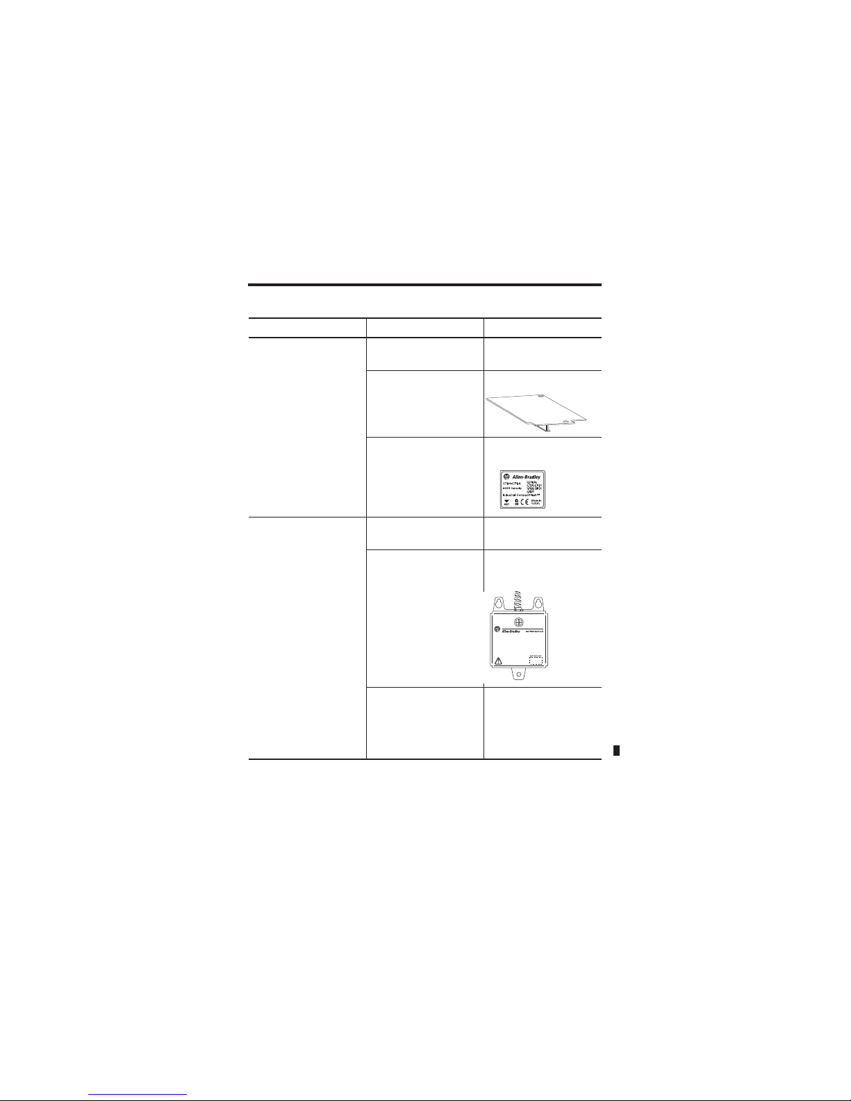
Required System Components
These components ship with the controller.
Yo u can use these components with th e controller.
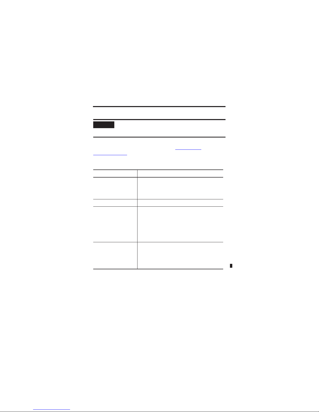
Component Description
Series A controllers: 1756-BA1 battery
Series B controllers: 1756-BA2 battery
Key
IMPORTANT
To maintain memory longer than is available with the battery, this option
maintains memory only while the controller is in the chassis.
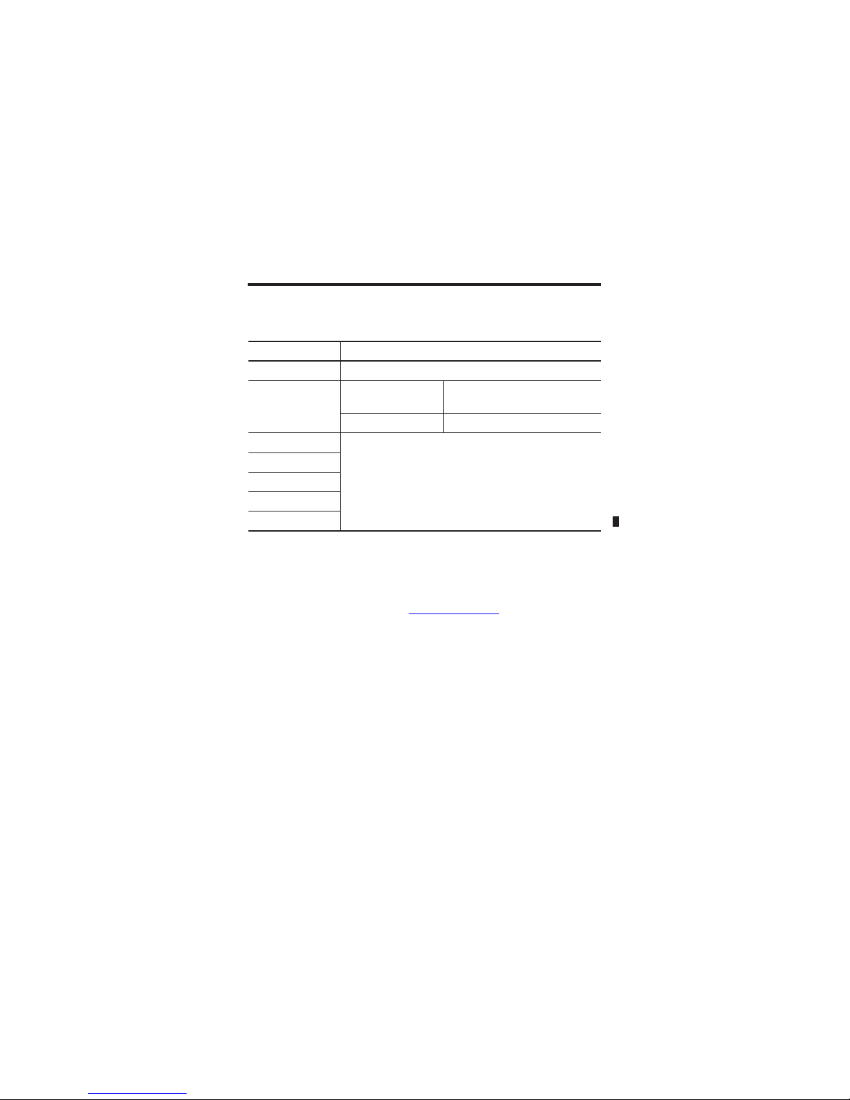
Optional Components
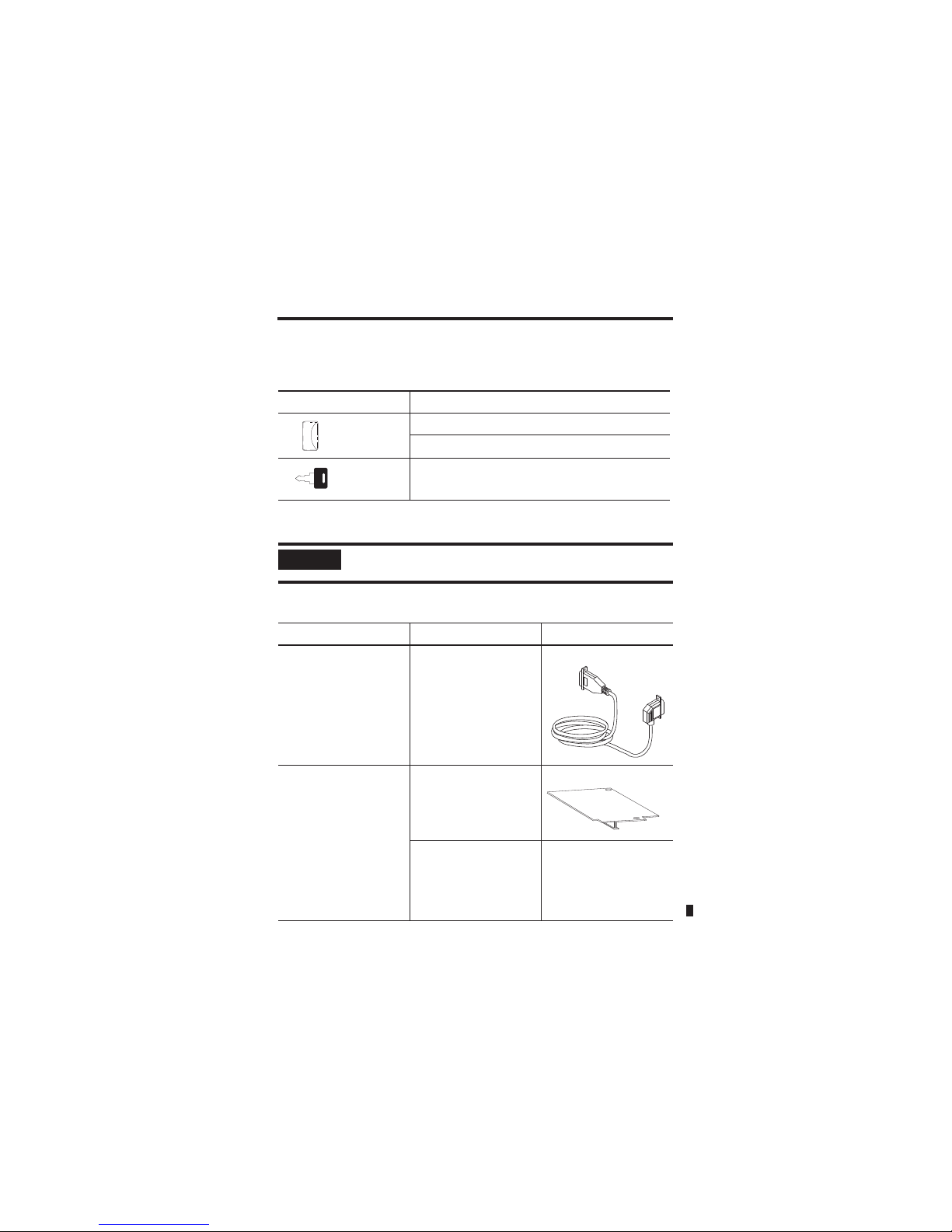
Description Controller Component
Connect a device to the
serial port of the controller
(for example, connect a
computer to the controller)
1756-CP3 serial cable.
Increase the memory of the
controller
ControlLogix5550
ControlLogix5555
Memory board.
ControlLogix5561
ControlLogix5562
ControlLogix5563
ControlLogix5564
ControlLogix5565
Not available for this
controller.
ControlLogix Controller and Memory Board 13
Publication
1756-IN101L-EN-P - June 2008
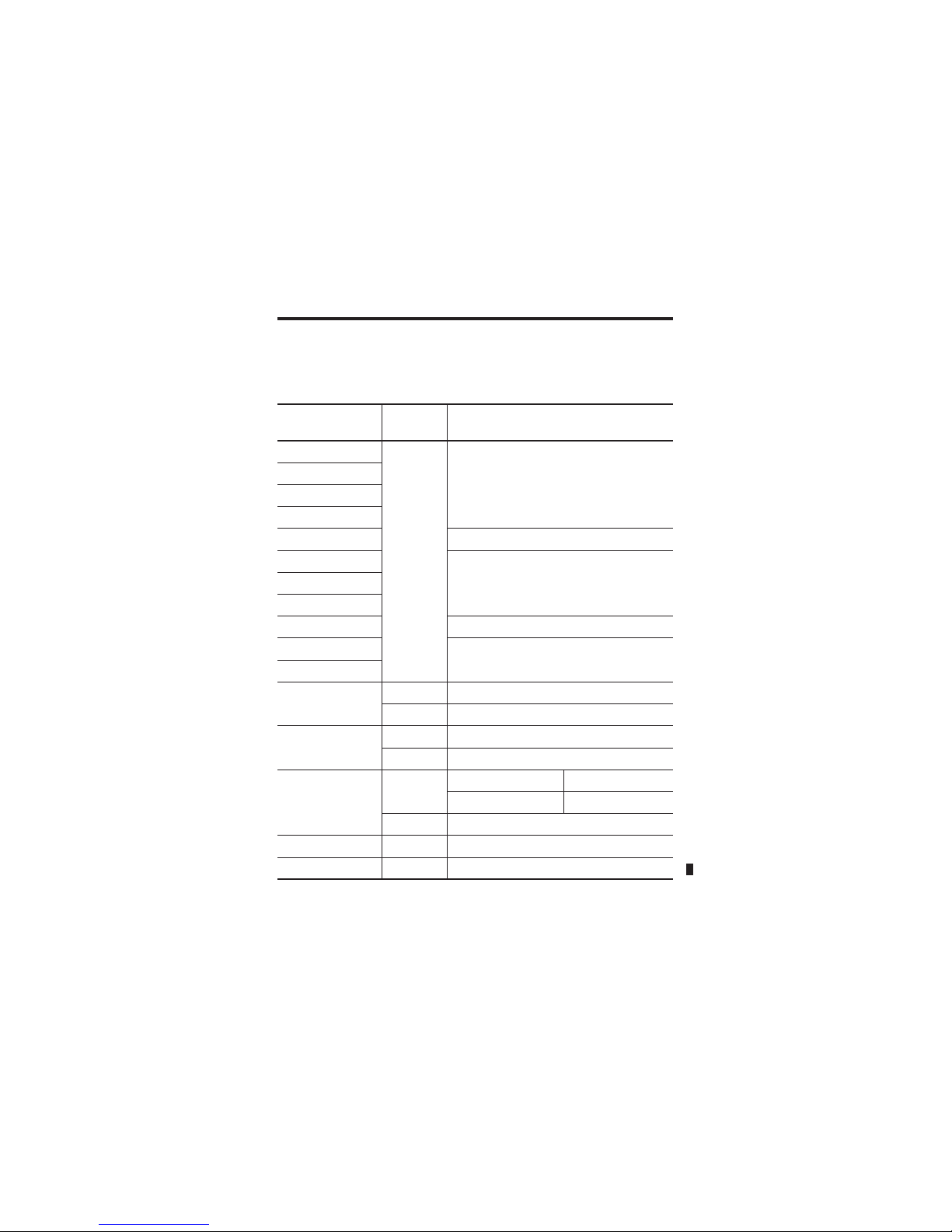
Add nonvolatile memory ControlLogix5550 Not available for this
controller.
ControlLogix5555 Memory board.
ControlLogix5561
ControlLogix5562
ControlLogix5563
ControlLogix5564
ControlLogix5565
1784-CF64 Industrial
CompactFlash Card.
31376-M
Maintain memory longer
than is available with the
battery
ControlLogix5550 Not available for this
controller.
ControlLogix5555
ControlLogix5561 Series A
ControlLogix5562 Series A
ControlLogix5563 Series A
1756-BATM ControlLogix
battery module.
ControlLogix5561 Series B
ControlLogix5562 Series B
ControlLogix5563 Series B
ControlLogix5564 Series B
ControlLogix5565 Series B
Not available for this
controller
(1)
.
(1)
Series B controllers use the battery differently than previous controllers. Battery life
depends on chassis temperature, project size, and how often you cycle power. Battery
life no longer depends on whether or not the controller has power.
Optional Components
Description Controller Component
31298
14 ControlLogix Controller and Memory Board
Publication
1756-IN101L-EN-P - June 2008
Firmware Revisions
To update the firmware of a controller, install a firmware upgrade kit. An
upgrade kit ships on a supplemental CD along with RSLogix 5000 software.
To download an upgrade kit, go to http://www.ab.com
and select Product
Support and Firmware Updates.
Memory Board
Controller Memory Board
ControlLogix5550 1756-M1, 1756-M2, 1756-M3
ControlLogix5555 No nonvolatile memory 1756-M12, 1756-M13, 1756-M14,
1756-M16
Nonvolatile memory 1756-M22, 1756-M23, 1756-M24
ControlLogix5561 Do not install a memory board.
ControlLogix5562
ControlLogix5563
ControlLogix5564
ControlLogix5565
ControlLogix Controller and Memory Board 15
Publication
1756-IN101L-EN-P - June 2008
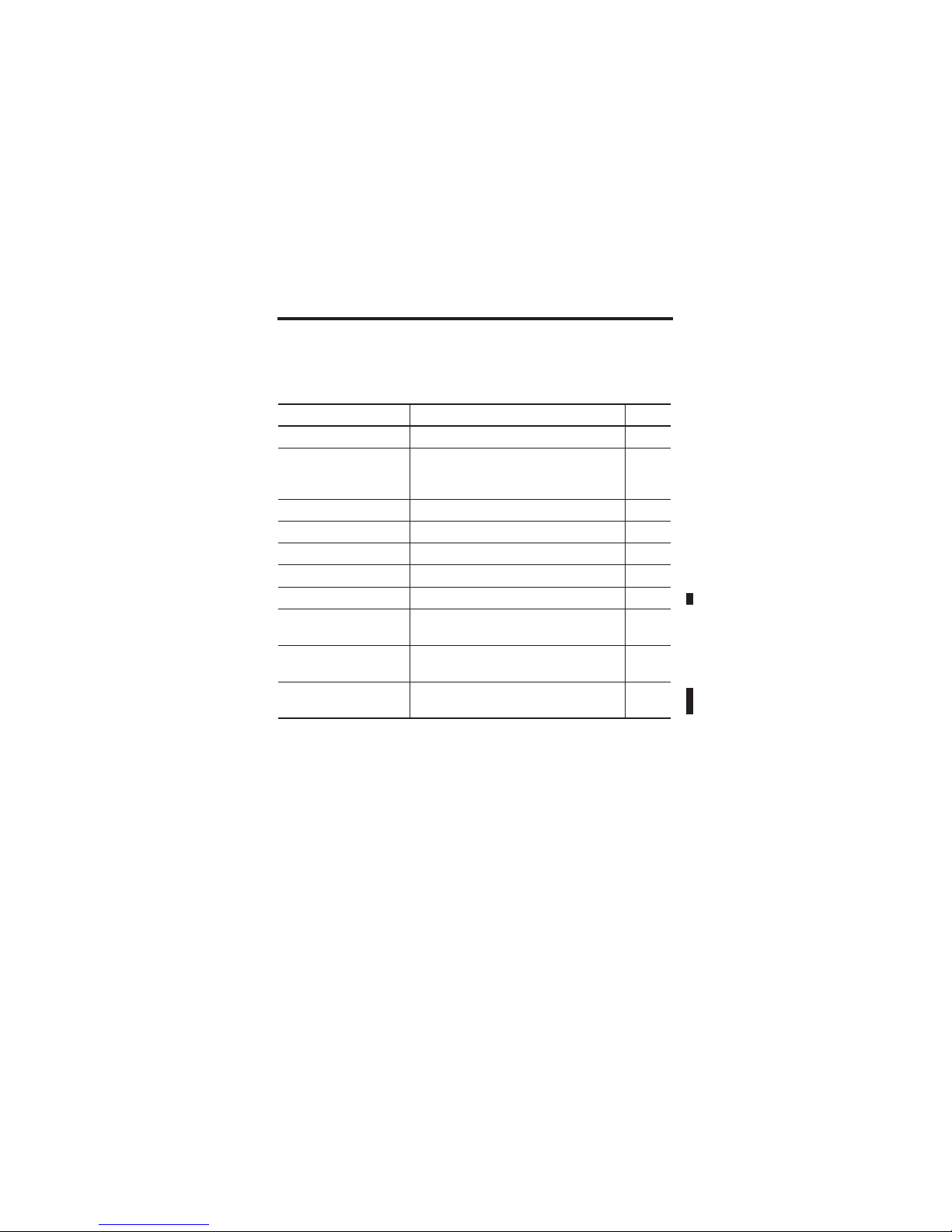
Use the following table to determine which firmware revisions to use with
your controller and memory board combination.
Make sure that the firmware revision is compatible with your version of
RSLogix 5000 software.
Controller and Memory Board Combinations
Controller and
Memory Board
Series Use this revision or later
1756-L1 None Any.
1756-L1M1
1756-L1M2
1756-L1M3
1756-L55M12 10.x or later.
1756-L55M13 6.x or later.
1756-L55M14
1756-L55M16
1756-L55M22 10.x or later.
1756-L55M23 8.x or later.
1756-L55M24
1756-L61 A 12.x or later.
B 13.40 or later.
1756-L62 A 12.x or later.
B 13.40 or later.
1756-L63 A No CompactFlash card 10.x or later.
CompactFlash card 11.x or later.
B 13.40 or later.
1756-L64 B 16 or later.
1756-L65 B 17 or later.
16 ControlLogix Controller and Memory Board
Publication
1756-IN101L-EN-P - June 2008
Preparing the Chassis
Before you install a controller:
x install a ControlLogix chassis.
x install a ControlLogix power supply.
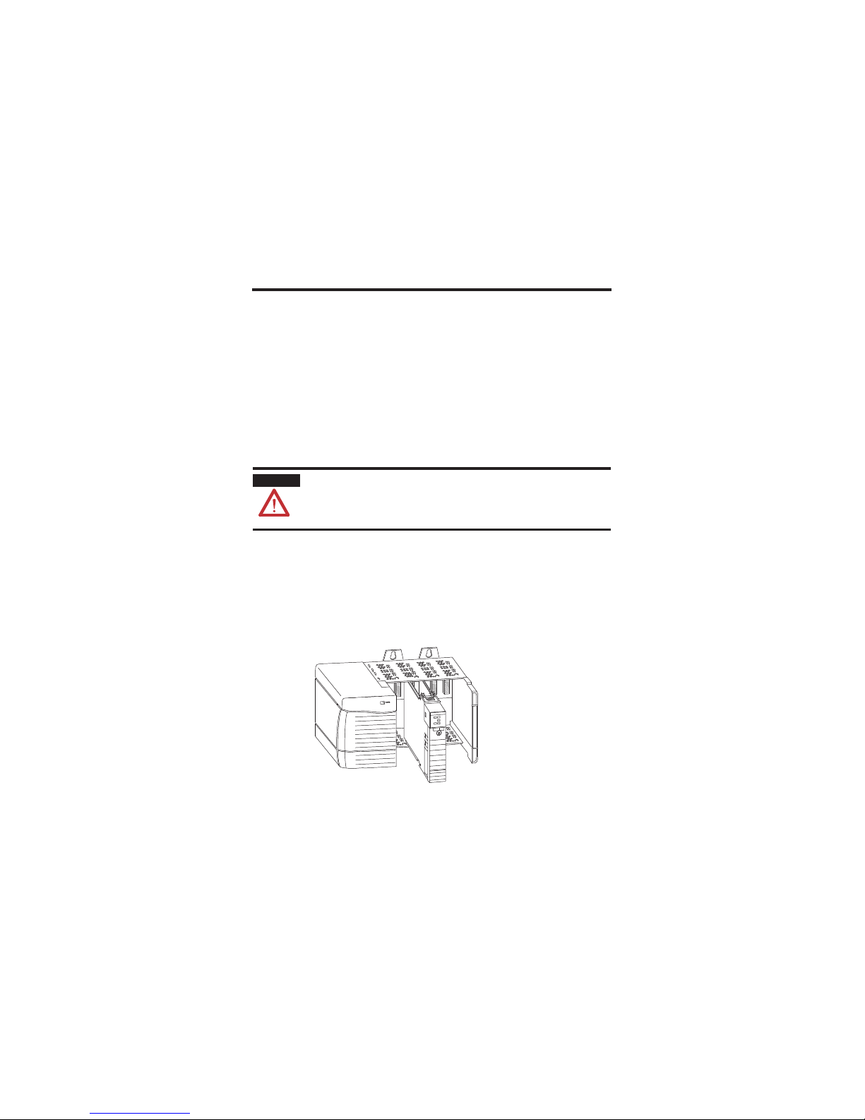
Remove the Controller from the Chassis
You can install or remove a controller while chassis power is on and the
system is operating. If you remove the controller, all the devices owned by the
controller go to their configured fault state.
Repeated electrical arcing causes excessive wear to contacts on both the
module and its mating connector. Worn contacts may create electrical
resistance that can affect module operation.
1. Press the lockin g tab s on the top and bottom of the controller.
2. Slide the controller out of the chassis.
WARNING
When you insert or remove the module while backplane power is on, an
electrical arc can occur. This could cause an explosion in hazardous location
installations. Be sure that power is removed or the area is nonhazardous
before proceeding.
20880
 Loading...