

Page 1
ControlLogix
Sequence of Events
Module
1756-IB16ISOE (24/48V dc),
1756-IH16ISOE (125V dc)
User Manual
Page 2
Important User Information
Solid state equipment has operational characteristics differing from those of
electromechanical equipment. Safety Guidelines for the Application,
Installation and Maintenance of Solid State Controls (Publication SGI-1.1
available from your local Rockwell Automation sales office or online at
http://www.ab.com/manuals/gi) describes some important differences
between solid state equipment and hard-wired electromechanical devices.
Because of this difference, and also because of the wide variety of uses for
solid state equipment, all persons responsible for applying this equipment
must satisfy themselves that each intended application of this equipment is
acceptable.
In no event will Rockwell Automation, Inc. be responsible or liable for
indirect or consequential damages resulting from the use or application of
this equipment.
The examples and diagrams in this manual are included solely for illustrative
purposes. Because of the many variables and requirements associated with
any particular installation, Rockwell Automation, Inc. cannot assume
responsibility or liability for actual use based on the examples and diagrams.
No patent liability is assumed by Rockwell Automation, Inc. with respect to
use of information, circuits, equipment, or software described in this manual.
Reproduction of the contents of this manual, in whole or in part, without
written permission of Rockwell Automation, Inc. is prohibited.
Throughout this manual we may use notes to make you aware of
safety considerations.
WARNING
IMPORTANT
ATTENTION
SHOCK HAZARD
BURN HAZARD
Identifies information about practices or circumstances
that can cause an explosion in a hazardous environment,
which may lead to personal injury or death, property
damage, or economic loss.
Identifies information that is critical for successful
application and understanding of the product.
Identifies information about practices or circumstances
that can lead to personal injury or death, property
damage, or economic loss. Attentions help you:
• identify a hazard
• avoid a hazard
• recognize the consequence
Labels may be located on or inside equipment to alert
people that dangerous voltage may be present.
Labels may be located on or inside equipment to alert
people that surfaces may be dangerous temperatures.
Page 3
Preface
Purpose of This Manual
This manual describes how to use the ControlLogix Sequence of
Events module in your ControlLogix application. With this manual,
you can learn how to install, configure and troubleshoot the module.
There are two types of ControlLogix Sequence of Events modules, as
described in Table Preface.1:
Table Preface.1
Catalog number: Description: Availability date:
1756-IB16ISOE 16-point, 10 - 50V dc module June 2004
1756-IH16ISOE 16-point, 90 - 140V dc
module
IMPORTANT
The two types of Sequence of Events modules have
identical functionality, except for the fact that they
operate at different voltage levels. Throughout this
manual, we use the term Sequence of Events module
generically. When you read the term, it refers to both
types of modules unless specifically noted.
April 2004
Who Should Use This Manual
This manual is intended for individuals who program ControlLogix
control systems, such as:
• software engineers
• control engineers
• application engineers
To most efficiently use the Sequence of Events module, you should be
familiar with:
• ControlLogix™ controllers
• ControlLogix ControlNet™ communication modules
• RSLogix 5000™
• RSNetWorx for ControlNet™
1 Publication 1756-UM528A-EN-P - April 2004
Page 4

Preface 2
What This Manual Contains
Table Preface.2 lists the sections contained in this manual:
Table Preface.2
Section: Title:
Chapter 1 What is the ControlLogix Sequence of Events Module?
Chapter 2 How Does the Sequence of Events Module Operate in a
ControlLogix System?
Chapter 3 Installing the Sequence of Events Module
Chapter 4 Configuring the Sequence of Events Module
Chapter 5 Using the Sequence of Events Module Features
Chapter 6 Using The Sequence of Events Module in CST Per Point Mode
Chapter 7 Using The Sequence of Events Module in FIFO Mode
Chapter 8 Troubleshooting the Sequence of Events Module
Appendix A Specifications and Module Block Diagrams
Appendix B Integrating The HiProm GPS Module (1756HP-GPS) into a
ControlLogix Sequence of Events Module System
Appendix C Using the Sequence of Events Module for Absolute First Fault
Detection
Appendix D Using Module Tags
Appendix E Using Sample RSLogix 5000 Projects with the Sequence of Events
Module
Related Documentation
Table Preface.3 lists related ControlLogix documentation that may
assist you when using the Sequence of Events module.
Table Preface.3 Related Documentation
Catalog
number:
1756-A4, -A7,
-A10, -A13, -A17
1756-PA72/B,
-PB72/B
1756-PA75,
-PB75
1756-PH75 ControlLogix 125V DC (90-143V) Power Supply 1756-IN589
1756-Series ControlLogix Module Installation Instructions
1756-CNB,
-CNBR
1756-Lx ControlLogix System User Manual 1756-UM001
Document title: Publication
number:
ControlLogix Chassis–Series B Installation
Instructions
ControlLogix Power Supply Installation
Instructions
ControlLogix Power Supply Installation
Instructions
(Each module has separate installation
document.)
Using ControlNet Communication Modules in
Logix5000 Control Systems User Manual
1756-IN080
1756-5.67
1756-5.78
Multiple 1756-IN
numbers
CNET-UM001
Publication 1756-UM528A-EN-P - April 2004
Page 5
Preface 3
Preventing Electrostatic Discharge
This module is sensitive to electrostatic discharge.
ATTENTION
This equipment is sensitive to electrostatic discharge,
which can cause internal damage and affect normal
operation. Follow these guidelines when you handle
this equipment:
• Touch a grounded object to discharge potential
static.
• Wear an approved grounding wriststrap.
• Do not touch connectors or pins on component
boards.
• Do not touch circuit components inside the
equipment.
• If available, use a static-safe workstation.
When not in use, store the equipment in appropriate
static-safe packaging.
Publication 1756-UM528A-EN-P - April 2004
Page 6
Preface 4
Environment and Enclosure
ATTENTION
This equipment is intended for use in a Pollution
Degree 2 industrial environment, in overvoltage
Category II applications (as defined in IEC
publication 60664-1), at altitudes up to 2000 meters
without derating.
This equipment is considered Group 1, Class A
industrial equipment according to IEC/CISPR
Publication 11. Without appropriate precautions,
there may be potential difficulties ensuring
electromagnetic compatibility in other environments
due to conducted as well as radiated disturbance.
This equipment is supplied as “open type”
equipment. It must be mounted within an enclosure
that is suitably designed for those specific
environmental conditions that will be present and
appropriately designed to prevent personal injury
resulting from accessibility to live parts. The interior
of the enclosure must be accessible only by the use
of a tool. Subsequent sections of this publication
may contain additional information regarding
specific enclosure type ratings that are required to
comply with certain product safety certifications.
See NEMA Standards publication 250 and IEC
publication 60529, as applicable, for explanations of
the degrees of protection provided by different types
of enclosure. Also, see the appropriate sections in
this publication, as well as the Allen-Bradley
publication 1770-4.1 (“Industrial Automation Wiring
and Grounding Guidelines”), for additional
installation requirements pertaining to this
equipment.
Publication 1756-UM528A-EN-P - April 2004
Page 7

What is the ControlLogix
Sequence of Events Module?
How Does the Sequence of Events
Module Operate in a ControlLogix
System?
Table of Contents
Chapter 1
What This Chapter Contains . . . . . . . . . . . . . . . . . . . . . . . 1-1
What does Sequence of Events Module Do? . . . . . . . . . . . . 1-1
Timestamping Using the Coordinated System Time (CST) 1-1
On-Board Data Storage . . . . . . . . . . . . . . . . . . . . . . . . 1-2
Two Modes of Operation . . . . . . . . . . . . . . . . . . . . . . . 1-3
What Else Does the Sequence of Event Module Do? . . . . . . 1-3
Understanding the Module’s Physical Features . . . . . . . . . . 1-4
Using Module Identification and Status Information . . . . . . 1-5
Chapter Summary and What’s Next . . . . . . . . . . . . . . . . . . 1-6
Chapter 2
What This Chapter Contains . . . . . . . . . . . . . . . . . . . . . . . 2-1
Differences Between Sequence of Events Module
and Standard Digital I/O . . . . . . . . . . . . . . . . . . . . . . . . . . 2-1
Similar Functionality to Standard ControlLogix DC
Input Modules . . . . . . . . . . . . . . . . . . . . . . . . . . . . . . . . . 2-2
Propagating a Signal From Field Device to Backplane . . . . 2-4
Sequence of Events Module in a Local Chassis . . . . . . . . . . 2-6
Requested Packet Interval (RPI) . . . . . . . . . . . . . . . . . . 2-6
Enable CST Capture . . . . . . . . . . . . . . . . . . . . . . . . . . . 2-6
Sequence of Events Module in a Remote Chassis . . . . . . . . 2-8
Remote Input Module Connected Via ControlNet . . . . . 2-8
Remote Input Modules Connected Via EtherNet/IP . . . . 2-10
Chapter Summary and What’s Next . . . . . . . . . . . . . . . . . . 2-10
Installing the Sequence of
Events Module
Chapter 3
What This Chapter Contains . . . . . . . . . . . . . . . . . . . . . . . 3-1
Installing the Sequence of Events Module. . . . . . . . . . . . . . 3-1
Keying the Removable Terminal Block. . . . . . . . . . . . . . . . 3-3
Connecting Wiring . . . . . . . . . . . . . . . . . . . . . . . . . . . . . . 3-4
Wiring the RTB . . . . . . . . . . . . . . . . . . . . . . . . . . . . . . 3-4
Recommendations for Wiring Your RTB . . . . . . . . . . . . 3-5
Wiring the Sequence of Events Module . . . . . . . . . . . . . . . 3-6
Assembling The Removable Terminal Block and
the Housing . . . . . . . . . . . . . . . . . . . . . . . . . . . . . . . . . . . 3-7
Choosing the Extended-Depth Housing . . . . . . . . . . . . . . . 3-8
Recommendations for Using the
Extended-Depth Housing . . . . . . . . . . . . . . . . . . . . . . . 3-9
Cabinet Size Considerations With the
Extended-Depth Housing . . . . . . . . . . . . . . . . . . . . . . . 3-9
Installing the Removable Terminal Block . . . . . . . . . . . . . . 3-10
Removing the Removable Terminal Block . . . . . . . . . . . . . 3-12
Removing the Module from the Chassis . . . . . . . . . . . . . . . 3-13
Chapter Summary and What’s Next . . . . . . . . . . . . . . . . . . 3-14
1 Publication 1756-UM528A-EN-P - April 2004
Page 8

Table of Contents 2
Configuring the Sequence of
Events Module
Using the Sequence of Events
Module Features
Chapter 4
What This Chapter Contains . . . . . . . . . . . . . . . . . . . . . . . 4-1
Configuring Your I/O Module . . . . . . . . . . . . . . . . . . . . . . 4-1
RSLogix 5000 Configuration Software . . . . . . . . . . . . . . 4-1
Overview of the Configuration Process . . . . . . . . . . . . . . . 4-2
Adding a New Module to Your RSLogix 5000 Project . . . . . 4-3
Communications Format. . . . . . . . . . . . . . . . . . . . . . . . 4-5
Electronic Keying. . . . . . . . . . . . . . . . . . . . . . . . . . . . . 4-5
Using the Default Configuration. . . . . . . . . . . . . . . . . . . . . 4-6
Altering the Default Configuration . . . . . . . . . . . . . . . . . . . 4-6
Downloading Configuration. . . . . . . . . . . . . . . . . . . . . . . . 4-7
Editing Configuration . . . . . . . . . . . . . . . . . . . . . . . . . . . . 4-7
Configuring Modules in a Remote Chassis . . . . . . . . . . . . . 4-9
Chapter Summary and What’s Next . . . . . . . . . . . . . . . . . . 4-11
Chapter 5
What This Chapter Contains . . . . . . . . . . . . . . . . . . . . . . . 5-1
Determining Module Compatibility . . . . . . . . . . . . . . . . . . 5-2
Module Features That Can Be Configured . . . . . . . . . . . . . 5-3
Two Operational Modes. . . . . . . . . . . . . . . . . . . . . . . . 5-3
Enable CST Capture . . . . . . . . . . . . . . . . . . . . . . . . . . . 5-5
Latch CST . . . . . . . . . . . . . . . . . . . . . . . . . . . . . . . . . . 5-7
Chatter Detection. . . . . . . . . . . . . . . . . . . . . . . . . . . . . 5-8
Software Configurable Input Filters. . . . . . . . . . . . . . . . 5-10
Electronic Keying. . . . . . . . . . . . . . . . . . . . . . . . . . . . . 5-13
Module Inhibiting . . . . . . . . . . . . . . . . . . . . . . . . . . . . 5-15
Other Inherent Module Features . . . . . . . . . . . . . . . . . . . . 5-16
Removal and Insertion Under Power (RIUP) . . . . . . . . . 5-16
Module Fault Reporting . . . . . . . . . . . . . . . . . . . . . . . . 5-16
Fully Software Configurable . . . . . . . . . . . . . . . . . . . . . 5-17
Producer/Consumer Model. . . . . . . . . . . . . . . . . . . . . . 5-17
Status Indicator Information . . . . . . . . . . . . . . . . . . . . . 5-18
Full Class I Division 2 Compliance . . . . . . . . . . . . . . . . 5-19
Agency Certifications . . . . . . . . . . . . . . . . . . . . . . . . . . 5-19
Chapter Summary and What’s Next . . . . . . . . . . . . . . . . . . 5-19
Publication 1756-UM528A-EN-P - April 2004
Page 9

Using The Sequence of Events
Module in CST Per Point Mode
Table of Contents 3
Chapter 6
What This Chapter Contains . . . . . . . . . . . . . . . . . . . . . . . 6-1
Overview of the Mode . . . . . . . . . . . . . . . . . . . . . . . . . . . 6-1
How Does the Module Store Timestamp Data in CST
Per Point Mode? . . . . . . . . . . . . . . . . . . . . . . . . . . . . . . . . 6-2
What Are The Typical Applications Where CST Per Point
Mode is Used?. . . . . . . . . . . . . . . . . . . . . . . . . . . . . . . . . . 6-4
Configuring the Module for CST Per Point Mode . . . . . . . . 6-4
Choosing a Communications Format. . . . . . . . . . . . . . . 6-5
Using Latch CST in CST Per Point Mode . . . . . . . . . . . . 6-6
Using Enable CST Capture in CST Per Point Mode. . . . . 6-7
Managing the Data in CST Per Point Mode . . . . . . . . . . . . . 6-8
Module Sends Data to the Controller . . . . . . . . . . . . . . 6-8
Copying Relevant Input Data to a Separate
Data Structure . . . . . . . . . . . . . . . . . . . . . . . . . . . . . . . 6-10
Acknowledging Latched Timestamp Data . . . . . . . . . . . 6-12
Sorting the Data . . . . . . . . . . . . . . . . . . . . . . . . . . . . . . . . 6-14
Clearing All Data From the Module’s Buffers At Once. . . . . 6-14
Chapter Summary and What’s Next . . . . . . . . . . . . . . . . . . 6-14
Using The Sequence of Events
Module in FIFO Mode
Chapter 7
What This Chapter Contains . . . . . . . . . . . . . . . . . . . . . . . 7-1
Overview of the Mode . . . . . . . . . . . . . . . . . . . . . . . . . . . 7-1
How Does the On-Board Buffer Work in FIFO Mode? . . . . 7-2
What the Typical Applications Where FIFO Mode is Used? . 7-4
Configuring the Module for FIFO Mode . . . . . . . . . . . . . . . 7-4
Choosing a Communications Format. . . . . . . . . . . . . . . 7-5
Using Latch CST in FIFO Mode. . . . . . . . . . . . . . . . . . . 7-6
Using Enable CST Capture in FIFO Mode . . . . . . . . . . . 7-9
Managing the Data in FIFO Mode . . . . . . . . . . . . . . . . . . . 7-10
Retrieving Data in FIFO Mode . . . . . . . . . . . . . . . . . . . 7-10
Producing Current Event Data . . . . . . . . . . . . . . . . . . . 7-14
Copying Relevant Input Data to a Separate
Data Structure . . . . . . . . . . . . . . . . . . . . . . . . . . . . . . . 7-15
Acknowledging Latched Timestamp Data . . . . . . . . . . . 7-17
Clearing All Data From the Module’s Buffers At Once. . . . . 7-20
Changing Between Retrieval Methods . . . . . . . . . . . . . . . . 7-20
Chapter Summary and What’s Next . . . . . . . . . . . . . . . . . . 7-20
Publication 1756-UM528A-EN-P - April 2004
Page 10

Table of Contents 4
Troubleshooting the Sequence of
Events Module
Specifications and Module
Block Diagrams
Integrating The HiProm GPS
Module (1756HP-GPS) into a
ControlLogix Sequence of Events
Module System
Chapter 8
What This Chapter Contains . . . . . . . . . . . . . . . . . . . . . . . 8-1
Using LED Status Indicators . . . . . . . . . . . . . . . . . . . . . . . . 8-1
Using RSLogix 5000 To Troubleshoot the Module. . . . . . . . 8-2
Determining Fault Type . . . . . . . . . . . . . . . . . . . . . . . . 8-4
Chapter Summary and What’s Next . . . . . . . . . . . . . . . . . . 8-4
Appendix A
1756-IB16ISOE Specifications. . . . . . . . . . . . . . . . . . . . . . . A-1
1756-IB16ISOE Module Block Diagram . . . . . . . . . . . . . . . A-4
1756-IH16ISOE Specifications . . . . . . . . . . . . . . . . . . . . . . A-5
1756-IH16ISOE Module Block Diagram . . . . . . . . . . . . . . . A-8
Appendix B
Overview . . . . . . . . . . . . . . . . . . . . . . . . . . . . . . . . . . . . . B-1
What is the 1756HP-GPS Module? . . . . . . . . . . . . . . . . . . . B-2
Correlating CST with UCT . . . . . . . . . . . . . . . . . . . . . . B-2
Determining the Absolute First Fault Across Multiple Chassis B-4
How Does the ControlLogix Controller Retrieve
Converted Value from the 1756HP-GPS Module? . . . . . . . . B-6
Converting Timestamps from CST Format to Universal
Coordinated Time Format . . . . . . . . . . . . . . . . . . . . . . . . . B-8
Synchronizing CSTs Across
Multiple Chassis
Using Module Tags
Using Sample RSLogix 5000
Projects with the Sequence of
Events Module
Glossary
Appendix C
Overview . . . . . . . . . . . . . . . . . . . . . . . . . . . . . . . . . . . . . C-1
Using a Time Master . . . . . . . . . . . . . . . . . . . . . . . . . . C-1
Configuring 1756-SYNCH Modules in RSLogix 5000. . . . C-3
Synchronizing Chassis in ControlLogix Redundancy Systems C-4
Related SynchLink Documentation. . . . . . . . . . . . . . . . . . . C-5
Appendix D
Fault and Status Reporting Between the Module
and Controllers . . . . . . . . . . . . . . . . . . . . . . . . . . . . . . . . . D-1
Module Tag Names and Definitions . . . . . . . . . . . . . . . . . . D-2
Tags Used in CST Point Per Mode . . . . . . . . . . . . . . . . D-2
Tags Used in FIFO Mode . . . . . . . . . . . . . . . . . . . . . . . D-7
Appendix E
Overview . . . . . . . . . . . . . . . . . . . . . . . . . . . . . . . . . . . . . E-1
Accessing the Sample Projects . . . . . . . . . . . . . . . . . . . . . . E-2
Index
Publication 1756-UM528A-EN-P - April 2004
Page 11

Chapter
What is the ControlLogix Sequence of
Events Module?
1
What This Chapter Contains
What does Sequence of Events Module Do?
This chapter describes the ControlLogix Sequence of Events module.
Table 1.1
For information on: See page:
What does Sequence of Events Module Do? 1-1
What Else Does the Sequence of Event Module Do? 1-3
Understanding the Module’s Physical Features 1-4
Using Module Identification and Status Information 1-5
The ControlLogix Sequence of Events module is a DC input module
that offers sub-millisecond timestamping on a per point basis in
addition to providing the basic ON/OFF detection as found on other
ControlLogix input modules.
Timestamping is a ControlLogix feature that registers a time reference
to a change in input data. In ControlLogix, the time mechanism used
for timestamping is the Coordinated System Time (CST).
Timestamping Using the Coordinated System Time (CST)
The Coordinated System Time (CST) is a 64-bit, free-running timer
with microsecond (µs) granularity on a ControlLogix backplane. A
time master (either a ControlLogix controller or 1756-SYNCH
module) generates the timer and sets it on the backplane. All other
modules in the chassis have access to the CST and adjust their time
reference based on the backplane time reference.
1 Publication 1756-UM528A-EN-P - April 2004
Page 12

1-2 What is the ControlLogix Sequence of Events Module?
CST cannot easily translate to real-time but serves as a relative time
reference. Each module in a chassis has access to this reference. The
Sequence of Events module grabs the current CST value at the time of
the input state change to timestamp the input data.
You can propagate the same CST value across multiple chassis,
effectively making sure that modules in separate chassis use the same
time reference in all their operations, if necessary.
You can extend a single CST value across multiple chassis that are
physically connected via 1756-SYNCH modules. Additionally, multiple
ControlLogix systems–even those that are geographically separated–
can use the 1756HP-GPS module to share a common real-time
reference. For more information on extending a single CST value
across multiple chassis, see Appendix C.
On-Board Data Storage
Once a CST timestamp is captured for an input transition, the
module’s operational mode impacts how the module functions with
respect to:
• what data is stored on-board
• how much data is stored for each input point
• how the data is sent to the controller
The next section briefly describes the two modes of operation
available with the Sequence of Events module and how they impact
the module’s behavior.
Publication 1756-UM528A-EN-P - April 2004
Page 13

What is the ControlLogix Sequence of Events Module? 1-3
Two Modes of Operation
The Sequence of Events module can operate in either of the modes
described in Table 1.2:
Table 1.2
Operational mode: Description:
CST Per Point Mode The module timestamps up to 2 input transitions per input, one for OFF to ON transitions and another
for ON to OFF transitions.
First In First Out (FIFO) Mode The module timestamps an unlimited number of input transitions, regardless of direction (i.e., either
OFF to ON or ON to OFF) or input (i.e., the same input can transition many times and the module will
timestamp every transition) and stores them in an on-board buffer.
The module is capable of storing the data for up to 160 input transitions in its on-board buffers at a
single time. However, if you retrieve data from the buffers effectively, the module will never miss an
input transition, regardless of how many occur.
You set the module’s operational mode when you choose a
communication format during initial module configuration.
Depending on operational mode, RSLogix 5000 creates different tags
for the Sequence of Events when it is added to a project.
What Else Does the Sequence of Event Module Do?
For more information on each mode, see Chapter 6, Using The
Sequence of Events Module in CST Per Point Mode and Chapter 7,
Using The Sequence of Events Module in FIFO Mode.
The Sequence of Events module offers additional features that are
common to ControlLogix digital input modules, such as:
• Full software configuration via RSLogix 5000
• Removal and insertion under power
• Full Class I Division Compliance
• Agency Certifications (e.g. UL and CSA)
To see a full description of all the features available on your Sequence
of Events module, see Chapter 5, Using the Sequence of Events
Module Features.
Publication 1756-UM528A-EN-P - April 2004
Page 14
1-4 What is the ControlLogix Sequence of Events Module?
Understanding the Module’s Physical Features
ControlLogix modules mount in a ControlLogix chassis and use a
Removable Terminal Block (RTB), or a Bulletin 1492 Interface Module
cable that connects to an IFM, to connect all field-side wiring. Before
you use your module, you should have already:
• installed and grounded a 1756 chassis and power supply. To
install these products, refer to the publications listed in
Table Preface.3 on page Preface-2.
• ordered and received an RTB or IFM and its components for
your application; neither RTBs nor IFMs are included with your
module purchase.
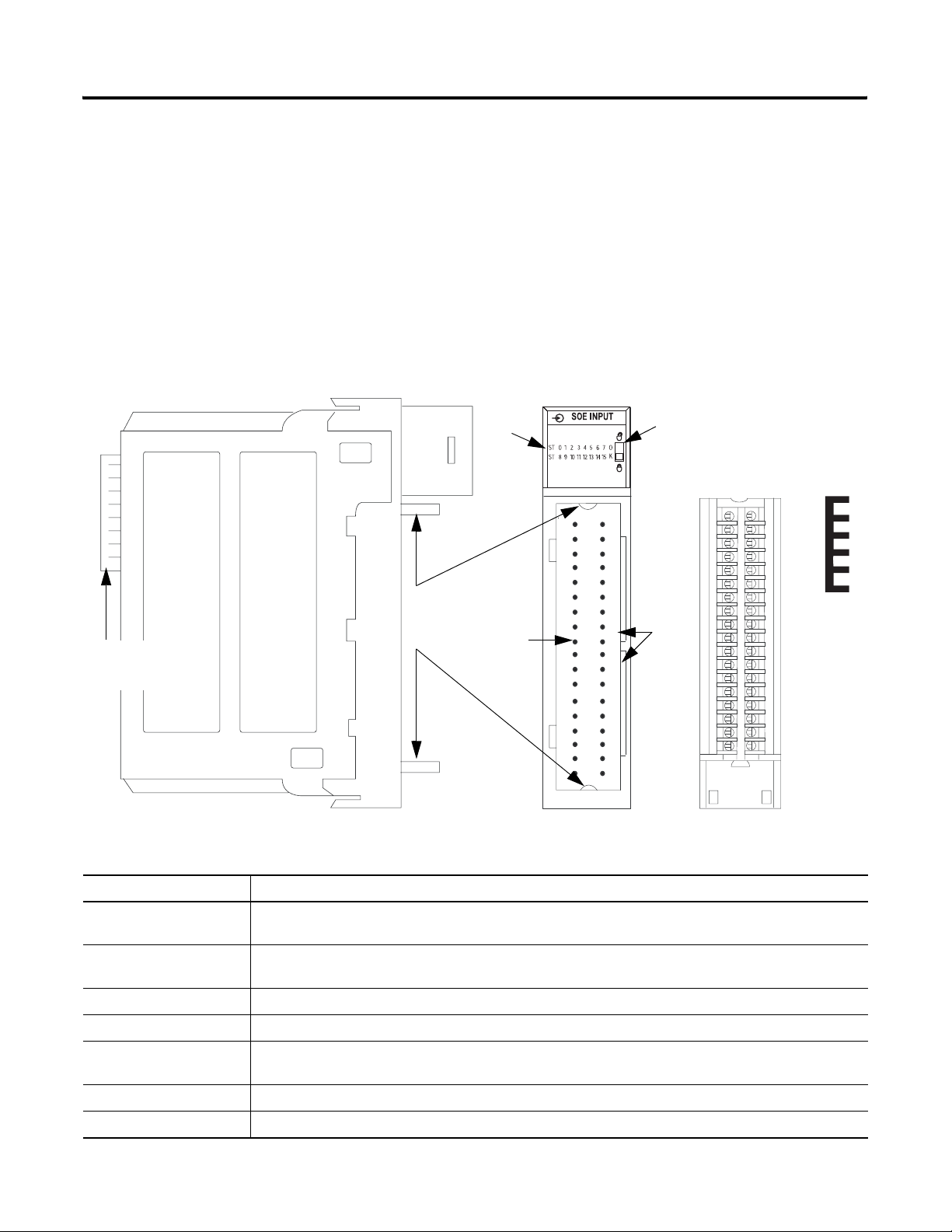
Figure 1.1
Indicators Locking tab
O
K
Removable terminal
block
Jumper
bar
Top and
ControlLogix
backplane
bottom
guides
Connector
pins
Slots
for
keying
the
RTB
41623
Table 1.3 Physical Features on the ControlLogix Sequence of Events Module
Physical Feature: Description:
Backplane connector The backplane connector interface for the ControlLogix system connects the module to the ControlLogix
backplane.
Connector pins Input/output, power and grounding connections are made to the module through these pins with the use of
an RTB or IFM.
Locking tab The locking tab anchors the RTB or IFM cable on the module, maintaining wiring connections.
Slots for keying Mechanically keys the RTB to prevent inadvertently making the wrong wire connections to your module.
Status indicators Indicators display the status of communication, module health and input/output devices. Use these
indicators to help in troubleshooting.
Top and bottom guides Guides provide assistance in seating the RTB or IFM cable onto the module.
Jumper bar Device you can use to connect multiple points in non-isolated wiring application, as shown on page 3-6.
Publication 1756-UM528A-EN-P - April 2004
Page 15
What is the ControlLogix Sequence of Events Module? 1-5
Using Module Identification and Status Information
Each Sequence of Events module maintains specific identification
information that separates it from all other modules. This information
assists you in tracking all the components of your system. For
example, you can track module identification information to be aware
of exactly what modules are located in any ControlLogix chassis at
any time. While retrieving module identity, you can also retrieve the
module’s status.
Each module maintains the information listed in Table 1.4:
Table 1.4 Module Identification and Status Information
Module Identification: Description:
Product Type Module’s product type
Product Code Module’s catalog number
Major Revision Module’s major revision number
Minor Revision Module’s minor revision number
Status Module’s status. Returns the following information:
• Controller ownership (if any)
• Whether module has been configured
• Device Specific Status, such as:
• Self-Test
• Flash update in progress
• Communications fault
• Not owned
• Internal fault (need flash update)
• Run mode
• Minor recoverable fault
• Minor unrecoverable fault
• Major recoverable fault
• Major unrecoverable fault
Vendor ID Module manufacturer vendor, for example Allen-Bradley
Serial Number Module serial number
Length of ASCII Text String Number of characters in module’s text string
ASCII Text String Module’s ASCII text string description
IMPORTANT
You must perform a WHO service to retrieve this
information.
Publication 1756-UM528A-EN-P - April 2004
Page 16

1-6 What is the ControlLogix Sequence of Events Module?
Chapter Summary and What’s Next
In this chapter you read about what the ControlLogix Sequence of
Events module is. Chapter 2 explains How Does the Sequence of
Events Module Operate in a ControlLogix System?
Publication 1756-UM528A-EN-P - April 2004
Page 17

Chapter
2
How Does the Sequence of Events Module
Operate in a ControlLogix System?
What This Chapter
This chapter describes how the Sequence of Events module
operates in a ControlLogix system.
Contains
Table 2.1
For information on: See page:
Ownership 2-2
Using RSNetWorx and RSLogix 5000 2-2
Propagating a Signal From Field Device to Backplane 2-4
Sequence of Events Module in a Local Chassis 2-6
Sequence of Events Module in a Remote Chassis 2-8
Differences Between Sequence of Events Module and Standard Digital I/O
Table 2.2
Difference: Description:
Additional data produced for
controller
Only one owner-controller per module While multiple controllers can simultaneously own other digital input modules, the Sequence of
In many aspects, the Sequence of Events module behaves the same as
other ControlLogix digital input modules. However, the module offers
several significant differences from other ControlLogix digital input
modules, including those described in Table 2.2:
The Sequence of Events module produces significantly more data for its owner-controller than
standard ControlLogix digital input modules. While other input modules only produce ON/OFF and
fault status, the Sequence of Events module produces data such as ON/OFF and fault status,
timestamp data, indication of whether new data was produced for specific input points or if
transitions were not timestamped.
Events module only supports a single owner-controller.
Rack-optimized connections not
supported
Change of State (COS) functionality in
Enable CST Capture feature
No listen-only connections Controllers cannot make listen-only connections to the Sequence of Events module. All
Input filtering on a module-wide basis Other digital input modules offer input filtering on a per group basis. The Sequence of Events
1 Publication 1756-UM528A-EN-P - April 2004
The Sequence of Events module does not support Rack-Optimized Connections from the
owner-controller.
The module does support Enable CST Capture, a feature used to timestamp input transitions, that
is analogous to COS. For more information on Enable CST Capture, see page 2-6.
connections between the module and its owner-controller are direct connections.
module offers two input filter settings–one for OFF to ON transitions and one for ON to OFF
transitions–and is set on a module-wide basis.
Page 18

2-2 How Does the Sequence of Events Module Operate in a ControlLogix System?
Similar Functionality to
With respect to general module operation in a ControlLogix system,
the Sequence of Events module operates similarly to other
Standard ControlLogix DC
Input Modules
ControlLogix digital input modules in many ways. This chapter
focuses on how the Sequence of Events module’s behavior differs
from that of other ControlLogix digital input modules.
However, you should be aware of aspects in which the Sequence of
Events module is similar to standard ControlLogix digital input
modules. For more information on these similarities, see Table 2.3.
Table 2.3 Ways that a Sequence of Events Module Behave Like Other ControlLogix Digital Input Modules
Concept: Description:
Ownership Every Sequence of Events module in the ControlLogix system must be owned by a Logix5000 controller. This
owner-controller:
• stores configuration data for every module that it owns.
• can be local or remote in regard to the Sequence of Events module’s position.
• sends the Sequence of Events module configuration data to define the module’s behavior and begin
operation with the control system.
This module does not support multiple owner-controllers.
Using RSNetWorx and
RSLogix 5000
The I/O configuration portion of RSLogix5000, v13 or greater, generates the configuration data for each
Sequence of Events module in the control system, whether the module is located in a local or remote chassis.
A remote chassis, also known as networked, contains the Sequence of Events module but not the module’s
owner-controller. Remote chassis can be connected to the controller via a scheduled ControlNet or an
EtherNet/IP network.
Configuration data is transferred to the controller during the program download and subsequently transferred
to the appropriate Sequence of Events modules.
Sequence of Events modules in the local chassis, and modules in a remote chassis that is connected via the
EtherNet/IP network, are ready to run as soon as the configuration data has been downloaded. However, you
must run RSNetWorx for ControlNet to enable Sequence of Events modules in a scheduled ControlNet
chassis.
Running RSNetWorx transfers configuration data to Sequence of Events modules on scheduled ControlNet
and establishes a Network Update Time (NUT) for ControlNet that is compliant with the desired
communications options specified for each module during configuration.
Anytime a controller references a Sequence of Events module in a scheduled ControlNet chassis, you must
run RSNetWorx to configure ControlNet. Follow these general guidelines when configuring Sequence of
Events modules:
1. Configure all Sequence of Events modules for a given controller using RSLogix 5000 and download
that information to the controller.
2. If the module configuration data references a module in a remote chassis connected by scheduled
ControlNet, run RSNetWorx.
3. After running RSNetWorx, perform an online save of the RSLogix 5000 project so the configuration
information that RSNetWorx sends to the controller is saved.
IMPORTANT: You must run RSNetWorx whenever a new module is added to a scheduled ControlNet
chassis. When a module is permanently removed from a remote chassis, we recommend that RSNetWorx be
run to optimize the allocation of network bandwidth.
Publication 1756-UM528A-EN-P - April 2004
Page 19

How Does the Sequence of Events Module Operate in a ControlLogix System? 2-3
Table 2.3 Ways that a Sequence of Events Module Behave Like Other ControlLogix Digital Input Modules
Concept: Description:
Making Connections ControlLogix controllers can make direct or rack connections to digital I/O modules. The controller can only make
a direct connection to the Sequence of Events module. The controller cannot make rack connections to the
Sequence of Events module. Additionally, the controller cannot make listen-only connections to the
Sequence of Events module.
A direct connection is a real-time data transfer link between the controller and the device that occupies the slot
that the configuration data references. When module configuration data is downloaded to an owner-controller,
the controller attempts to establish a direct connection to each of the modules referenced by the data.
If a controller has configuration data referencing a slot in the control system, the controller periodically checks for
the presence of a device there. When a device’s presence is detected there, the controller automatically sends the
configuration data.
If the data is appropriate to the module found in the slot, a connection is made and operation begins. If the
configuration data is not appropriate, the data is rejected and an error message appears in the software. In this
case, the configuration data can be inappropriate for any of a number of reasons. For example, a module’s
configuration data may be appropriate except for a mismatch in electronic keying.
The controller maintains and monitors its connection with a module. Any break in the connection, such as module
faults or removal of the module from the chassis while under power, causes the controller to set fault status bits
in the data area associated with the module. RSLogix 5000 monitors connection status to annunciate the
modules’ failures.
Transmitting Data In the ControlLogix system, a controller does not poll the Sequence of Events module to obtain input status. When
you configure a Sequence of Events module to capture a CST value for a specific transition, the module produces
data whenever that input transitions and also at a user-configured rate. The type of input data transmitted and
transmission frequency depends on module configuration and where in the control system that input module
physically resides.
Triggering Event
Tasks
This is called the Producer/Consumer model. The Sequence of Events module produces the input data and the
controller consumes the data.
All Sequence of Events module inputs are updated asynchronous to the controller’s task execution. In other
words, an input may be updated in the controller at any time during the controller’s execution of the tasks it is
configured to run. The input device determines when the input is sent, based on its configuration.
You can configure Sequence of Events modules to trigger an event task. The event task offers ControlLogix
controller users a task that executes a section of logic immediately when an event (i.e., receipt of new, unseen,
data) occurs.
Your Sequence of Events module can trigger event tasks. When using a Sequence of Events module to trigger an
event task, remember these considerations:
• Only one input module can trigger a specific event task.
• The input module triggers the event task based on the Enable CST Capture configuration for the module.
The Enable CST Capture configuration defines which points prompt the module to produce data if they turn
ON or OFF. This production of data triggers the event task.
• Typically, Enable CST Capture for only one point on the module. If you Enable CST Capture for multiple
points, a task overlap of the event task may occur.
For more information on using Event tasks, see the Logix5000 Controllers Common Procedures Programming
Manual, publication 1756-PM001.
Publication 1756-UM528A-EN-P - April 2004
Page 20

2-4 How Does the Sequence of Events Module Operate in a ControlLogix System?
Propagating a Signal From Field Device to Backplane
As shown in Figure 2.1, the Sequence of Events module receives a
signal at the RTB and processes it internally before sending a signal to
the ControlLogix backplane via the Requested Packet Interval (RPI) or
at na Enable CST Capture occurrence.
However, when you operate the Sequence of Events module, you
must account for signal propagation delays that exist during internal
processing. Some of these delays are inherent to the module and
others can be controlled via the user-defined module configuration.
During processing, the following delays exist:
• hardware delay - varies according to module type (i.e., catalog
number) and input transition type (i.e., OFF to ON/ON to OFF)
IMPORTANT
The hardware delay is relatively consistent across
inputs on a module and across modules in a chassis.
Therefore, assuming the inputs and modules are
used in similar environmental conditions and with
similar voltages applied, the hardware delay is a
minor consideration affecting timestamping accuracy.
• input filter delay - user-configurable number from 0 to 50ms
• firmware scan time - up to 25µs, depending on when the input
transitions relative to the sample time
• ASIC delay - 25µs
Typically, the Sequence of Events module can deliver a signal to the
ControlLogix backplane within 275µs in FIFO mode and 725µs in CST
Per Point mode after it was received at the removable terminal block
(RTB); these 275µs or 725µs numbers represent a scenario where the
hardware delay is at maximum levels but no input filter is used.
TIP
For fastest propagation of a signal from a field device
to the controller, use the module in FIFO mode in a
local chassis.
Publication 1756-UM528A-EN-P - April 2004
Page 21
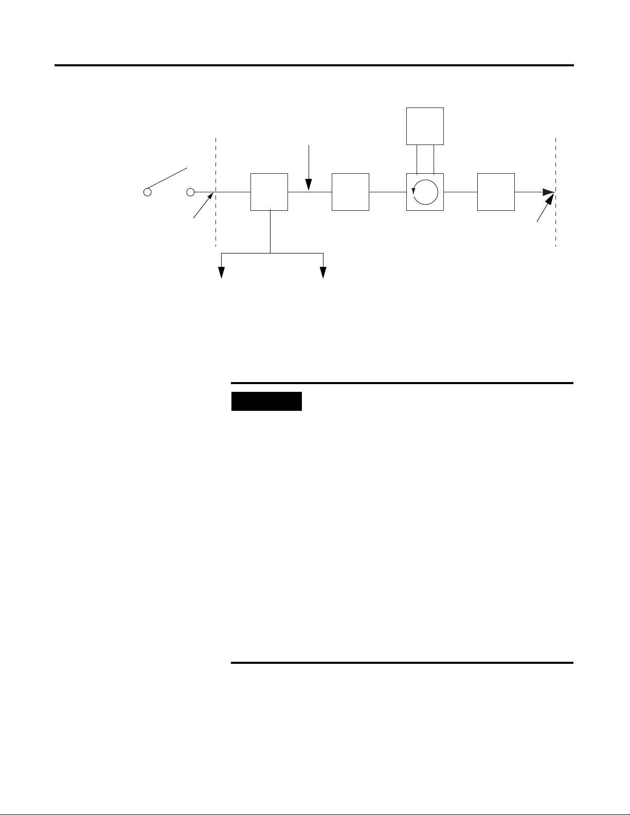
Figure 2.1
How Does the Sequence of Events Module Operate in a ControlLogix System? 2-5
Digital
CST captured here
signal
processor
Signal applied
at the RTB
For OFF to ON:
For ON to OFF:
1756-IB16ISOE
• 10µs - nominal
• 20µs - maximum
• 25µs - nominal
• 50µs - maximum
EXAMPLE
Hardware
delay
For OFF to ON:
For ON to OFF:
Filter
delay
User configurable
0 - 50ms
1756-IH16ISOE
• 10µs - nominal
• 20µs - maximum
• 50µs - nominal
• 75µs - maximum
Scan
time
Up to 25µs
ASIC
delay
Typi ca ll y
175µs - FIFO
mode or
625µs - CST
Per Point
mode
Many factors (e.g. voltage, operating temperature, if
the module is turning ON or OFF) affect the signal
propagation delay on a module. But a nominal delay
time can be estimated.
For example, if you are turning ON a
1756-IB16ISOE module at 24V dc in 25°C
conditions, the signal propagation delay is
affected by:
Signal
sent to
backplane
42701
• hardware delay to energize the module
(nominally 10µS on this module)
• user-configurable input filter time (0 to 50ms)
• firmware scan time (up to 25µs)
• ASIC delay (175µs - FIFO mode/625µs - CST Per
Point mode)
In the typical case scenario (i.e., filter time of 0ms),
the module has a signal propagation delay of
approximately 210µs (FIFO) to 660µs (CST Per
Point).
Publication 1756-UM528A-EN-P - April 2004
Page 22

2-6 How Does the Sequence of Events Module Operate in a ControlLogix System?
Sequence of Events Module in a Local Chassis
When a Sequence of Events module resides in the local chassis (i.e.,
the same chassis as the owner-controller), the following two
configuration parameters affect how and when an input module
multicasts data:
Requested Packet Interval (RPI)
This interval specifies the rate at which a module multicasts its data to
the controller. The time ranges from 250µs to 750ms and is sent to the
module with all other configuration parameters. When the specified
time frame elapses, the module multicasts data. This is also called a
cyclic update.
Because each operational mode (CST Per Point or FIFO) generates a
unique set of controller tags, the operational mode determines exactly
what data is sent to the controller at the RPI. For more information on
which tags are generated in each operational mode and, therefore,
what data is sent to the controller at each RPI, see Appendix D, Using
Module Tags.
• Requested Packet Interval (RPI)
• Enable CST Capture
Enable CST Capture
Enable CST Capture instructs the Sequence of Events module to
capture the CST whenever specific input points transition. You can
use this feature to instruct the module to capture the CST when the
inputs transition from:
• OFF to ON only
• ON to OFF only
or
• both OFF to ON and ON to OFF
Publication 1756-UM528A-EN-P - April 2004
Page 23

How Does the Sequence of Events Module Operate in a ControlLogix System? 2-7
When Enable CST Capture is enabled for specific points and
transitions occur for those points, the Sequence of Events
module not only captures the CST at the transition occurrence
but also sends input data to the controller.
Because the RPI and Enable CST Capture functions are asynchronous
to the program scan, it is possible for an input to change state during
program scan execution. The point must be “buffered” to prevent this.
Copy the input data from your input tags to another structure and use
the data from there.
TIP
IMPORTANT
To minimize traffic and conserve bandwidth, we
recommend you use a larger RPI value if the
Enable CST Capture option is used and the module
is located in the same chassis as its owner.
All points on the Sequence of Events module have
Enable Capture CST enabled by default for both
ON to OFF and OFF to ON.
Additionally, you must specify an RPI regardless of
whether you use Enable Capture CST on any input
points. The default RPI at module creation in an
RSLogix 5000 project is 10ms.
Publication 1756-UM528A-EN-P - April 2004
Page 24
2-8 How Does the Sequence of Events Module Operate in a ControlLogix System?
Sequence of Events Module
If your Sequence of Events module physically resides in a chassis
other than where the owner-controller is (e.g. a remote chassis
in a Remote Chassis
connected via ControlNet), the role of the RPI and the module’s
Enable CST Capture behavior changes slightly with respect to getting
data to the owner-controller.
The RPI and Enable CST Capture behavior still define when the
module multicasts data within its own chassis (as described in the
previous section), but only the value of the RPI determines when the
owner-controller receives it over the network.
Remote Input Module Connected Via ControlNet
When a Sequence of Events module resides in a remote chassis
connected by a scheduled ControlNet network, the RPI:
• instructs the module to multicast data in its own chassis at a
specific interval.
• reserves a “spot” in the stream of data flowing across the
ControlNet network.
The timing of this “reserved” spot may or may not coincide with the
exact value of the RPI, but the control system guarantees that the
owner-controller receives data at least as often as the specified RPI.
Figure 2.2 Sequence of Events Module in Remote Chassis with Data Coming At
Least as Often as RPI
Owner-controller ControlNet Bridge module Sequence of Events moduleControlNet Bridge module
Input data multicast in
module’s chassis at RPI
Input data at least as often as RPI
ControlNet
40947
Publication 1756-UM528A-EN-P - April 2004
Page 25

How Does the Sequence of Events Module Operate in a ControlLogix System? 2-9
The “reserved” spot on the network and the module’s RPI are
asynchronous to each other. This means there are Best and Worst Case
scenarios as to when the owner-controller will receive updated
channel data from the module in a remote chassis.
Best Case RPI Multicast Scenario
In the Best Case scenario, the module performs an RPI multicast with
updated channel data just before the “reserved” network slot is made
available. In this case, the owner-controller receives the data almost
immediately.
Worst Case RPI Multicast Scenario
In the Worst Case scenario, the module performs an RPI multicast just
after the “reserved” network slot has passed. In this case, the
owner-controller does not receive data until the next available
network slot.
IMPORTANT
Enabling the Enable CST Capture feature on an
input module in a remote chassis allows the
module to multicast data at both the RPI rate and
when the input changes state. This helps to
reduce the Worst Case time.
Table 2.4 summarizes the Best Case and Worst Case scenarios, from
the time an input changes state to the time the owner-controller will
receive the data:
Table 2.4 Best and Worst Case Scenarios For Remote Input Data Transfer
Best case scenario Worst case scenario
Enable CST Capture
disabled
Enable CST Capture
enabled
Backplane/Network
transfer times (<1mS)
Backplane/Network
transfer times (<1mS)
Twice the RPI
RPI
Publication 1756-UM528A-EN-P - April 2004
Page 26

2-10 How Does the Sequence of Events Module Operate in a ControlLogix System?
When selecting values for the remotely located module’s RPI,
system throughput is optimized when its RPI value is a power of 2
times the current NUT running on ControlNet.
For example, Table 2.5 shows recommended RPI values for a system
using a NUT of 5mS:
Table 2.5 Recommended RPI Values for System Using NUT of 5mS
NUT=5mS
Optimal
RPI Values
(mS)
0
x2
5mS 10mS 20mS 40mS 80mS 160mS 320mS 640mS
x2
1
x2
2
x2
3
x2
4
x2
5
x2
6
x2
7
Remote Input Modules Connected Via EtherNet/IP
When the Sequence of Events module is connected to the
owner-controller via an EtherNet/IP network, data is transferred to
the owner-controller in the following way:
• At the RPI or on an Enable CST Capture event, the module
multicasts data within its own chassis.
• The 1756-ENBT module in the remote chassis immediately
sends the module’s data over the network to the
owner-controller as long as it has not sent data within a time
frame that is 1/4 the value of the digital input module’s RPI.
For example, if a Sequence of Events module uses an RPI =
100ms, the 1756-ENBT module only sends module data
immediately on receiving it if another data packet was not
sent within the last 25ms.
Chapter Summary and What’s Next
Publication 1756-UM528A-EN-P - April 2004
In this chapter you read about how the Sequence of Events module
operates in a ControlLogix system.
Chapter 3 explains the Installing the Sequence of Events Module.
Page 27
Chapter
3
Installing the Sequence of Events Module
What This Chapter Contains
Installing the Sequence of
Events Module
This chapter describes how to install the Sequence of Events
module.
Table 3.1
For information on: See page:
Installing the Sequence of Events Module 3-1
Keying the Removable Terminal Block 3-3
Connecting Wiring 3-4
Assembling The Removable Terminal Block and the Housing 3-7
Choosing the Extended-Depth Housing 3-8
Installing the Removable Terminal Block 3-10
Removing the Removable Terminal Block 3-12
Removing the Module from the Chassis 3-13
You can install or remove the module while chassis power is
applied.
ATTENTION
The module is designed to support Removal and
Insertion Under Power (RIUP). However, when
you remove or insert an RTB with field-side power
applied, unintended machine motion or loss of
process control can occur. Exercise extreme
caution when using this feature.
1 Publication 1756-UM528A-EN-P - April 2004
Page 28
3-2 Installing the Sequence of Events Module
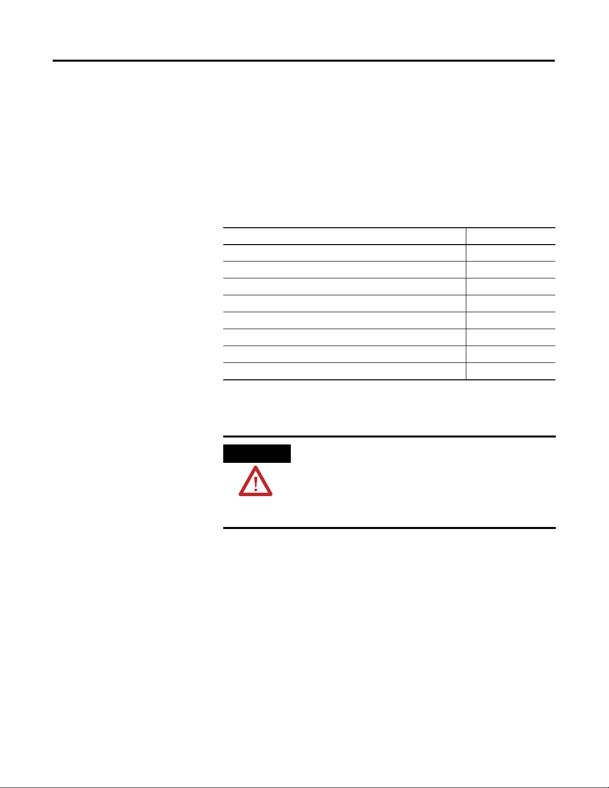
1. Align circuit board with top and bottom chassis guides.
Figure 3.1
Printed Circuit Board
20861-M
2. Slide module into chassis until module tabs ‘click’.
Figure 3.2
Locking Tab
20862-M
Publication 1756-UM528A-EN-P - April 2004
Page 29
Installing the Sequence of Events Module 3-3
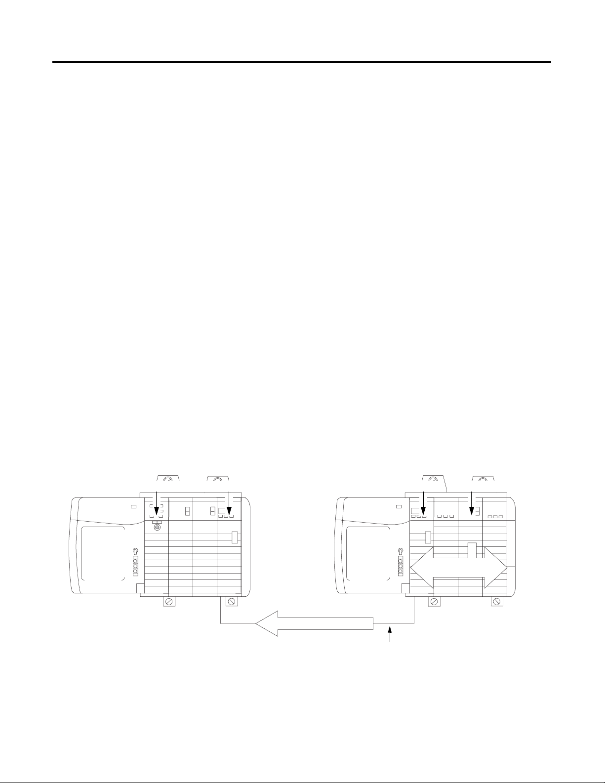
Keying the Removable Terminal Block
Key the RTB to prevent inadvertently connecting the incorrect RTB
to your module. When the RTB mounts onto the module, keying
positions match up. For example, if you place a U-shaped keying
band in position #4 on the module, you cannot place a
wedge-shaped tab in #4 on the RTB or your RTB does not mount
on the module. We recommend that you use a unique keying
pattern for each slot in the chassis.
1. Insert the U-shaped band with the longer side near the
terminals. Push the band onto the module until it snaps in
place.
Figure 3.3 .
U-shaped
Keying Band
20850-M
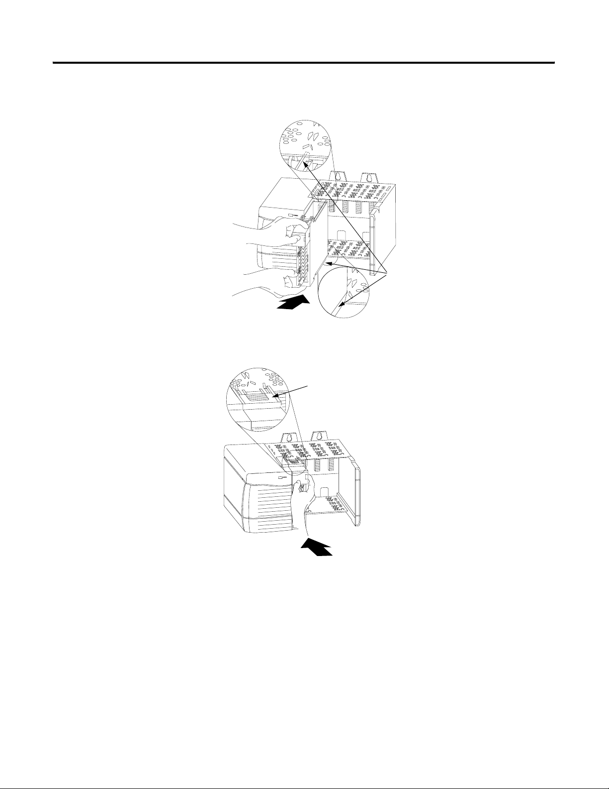
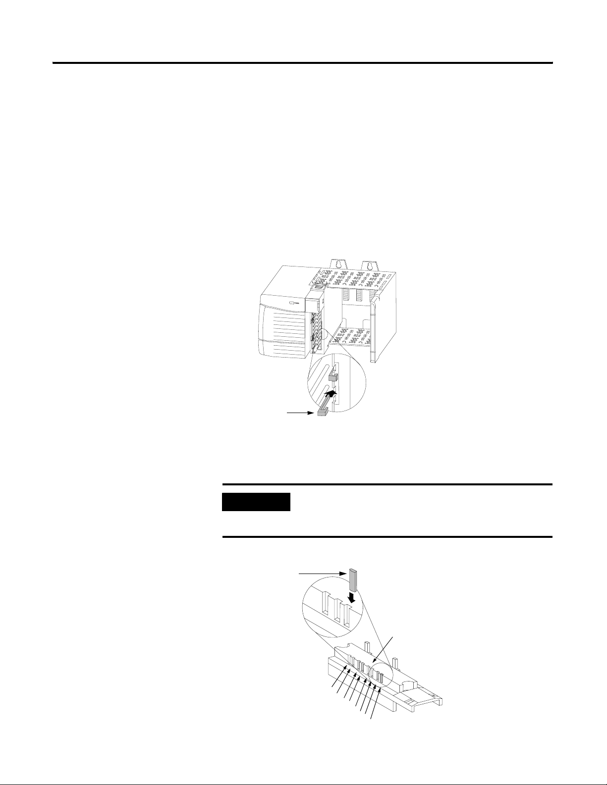
2. Key the RTB in positions that correspond to unkeyed module
positions. Insert the wedge-shaped tab on the RTB with the
rounded edge first. Push the tab onto the RTB until it stops.
IMPORTANT
When keying your RTB and module, you must
begin with a wedge-shaped tab in position #6 or
#7.
Figure 3.4
Wedge–shaped
Keying Tab
Module side of RTB
0
1
2
3
4
5
6
7
Publication 1756-UM528A-EN-P - April 2004
20851–M
Page 30
3-4 Installing the Sequence of Events Module
Connecting Wiring
You can use an RTB or a Bulletin 1492 prewired Interface Module
(IFM) to connect wiring to your module. You must connect wires
to the RTB. An IFM has been prewired before you received it. If
you are using an IFM to connect wiring to the module, skip this
section and go to page 3-7.
Wiring the RTB
You can use either of the following RTBs with your Sequence of
Events module.
• Cage Clamp RTB - Catalog number 1756-TBCH
• Spring Clamp RTB - Catalog number 1756-TBS6H
Wire the RTB with a 1/8 inch (3.2mm) maximum flat-bladed
screwdriver before installing it onto the module.
WARNING
When you connect or disconnect the Removable
Terminal Block (RTB) while field side power is on,
an electrical arc can occur. This could cause an
explosion in hazardous location installations.
Be sure that power is removed or that the area is nonhazardous
before proceeding.
Cage Clamp RTB
1. Strip 3/8 inch (9.5mm) maximum length of wire.
2. Insert the wire into the open terminal.
3. Turn the screw clockwise to close the terminal on the wire.
Figure 3.5
Strain relief area
20859-M
Publication 1756-UM528A-EN-P - April 2004
Page 31

Installing the Sequence of Events Module 3-5
Spring Clamp RTB
1. Strip 7/16 inch (11mm) maximum length of wire.
2. Insert the screwdriver into the inner hole of the RTB.
3. Insert the wire into the open terminal and remove the
screwdriver.
Figure 3.6
Strain relief area
20860-M
Recommendations for Wiring Your RTB
Consider the following guidelines when wiring your RTB:
• Begin wiring the RTB at the bottom terminals and move up.
• Use a tie to secure the wires in the strain relief area of the
RTB.
• The jumper bar part number is 97739201. Contact your local
Rockwell Automation sales representative to order additional
jumper bars, if necessary.
• Order and use an extended-depth housing (Catalog
number 1756-TBE) for applications that require heavy gauge
wiring. For more information, see page 3-8.
Publication 1756-UM528A-EN-P - April 2004
Page 32

3-6 Installing the Sequence of Events Module
Wiring the Sequence of Events Module
Isolated wiring
DC-0 (-)
DC-1 (-)
Source input wiring
DC-5 (-)
DC-6 (-)
Non-isolated wiring
Jumper bar
(Cut to length)
Use Figure 3.7 to wire your Sequence of Events module.
WARNING
If you connect or disconnect wiring while the
field-side power is on, an electrical arc can occur.
This could cause an explosion in hazardous
location installations. Be sure that power is
removed or the area is nonhazardous before
proceeding.
Figure 3.7
Sink input wiring
GND-0
GND-1
GND-2
GND-3
GND-4
GND-5
GND-6
GND-7
GND-8
GND-9
GND-10
GND-11
GND-12
GND-13
GND-14
12
34
56
78
910
1112
1314
1516
1718
1920
2122
2324
2526
2728
2930
IN-0
IN-1
IN-2
IN-3
IN-4
IN-5
IN-6
IN-7
IN-8
IN-9
IN-10
IN-11
IN-12
IN-13
IN-14
DC-0 (+)
DC-1 (+)
Source input wiring
DC-5 (+)
DC-6 (+)
Sink input wiring
DC (-)
Daisy chain to other RTBs
NOTES:
1. All terminals with the same name are connected together on the module. For example, DC (-) can be connected to either terminal marked
GND-15.
2. When you use the second GND-15 terminal to daisy chain to other RTBs, always connect the daisy chain to the terminal directly connected
to the supply wire, as shown in the example above.
3. If separate power sources are used, do not exceed the specified isolation voltage.
4. Do not connect more than 2 wires to any single terminal.
5. The jumper bar part number is 97739201. Contact your local Rockwell Automation sales representative to order jumper bars, if necessary.
Publication 1756-UM528A-EN-P - April 2004
GND-15
GND-15
Not used
3132
3334
3536
IN-15
Not used
Not used
DC (+)
40167-M
Page 33

Installing the Sequence of Events Module 3-7
Assembling The Removable
Removable housing covers the wired RTB to protect wiring
connections when the RTB is seated on the module.
Terminal Block and
the Housing
Figure 3.8
1. Align the grooves at the bottom of each side of the housing
with the side edges of the RTB.
Housing
Groove
Side edge of RTB
Groove
Strain relief area
Side edge of RTB
RTB
1756-TBCH RTB shown for reference
2. Slide the RTB into the housing until it snaps into place.
IMPORTANT
If additional wire routing space is required for your
application, use extended-depth housing
1756-TBE.
20858-M
Publication 1756-UM528A-EN-P - April 2004
Page 34

3-8 Installing the Sequence of Events Module
Choosing the Extended-Depth Housing
There are two housing options you must consider when wiring
your Sequence of Events module–standard-depth or extended-depth.
When you order an RTB for your module, you receive a
standard-depth housing with the RTB. If your application uses
heavy gauge wiring, you can order an extended-depth housing.
This housing does not come with an RTB.
You can use one of the housings listed in Table 3.2.
Table 3.2
Use this
housing:
1756-TBCH Cage clamp 336 sq. mm
1756-TBS6H Spring clamp (36-position)
1756-TBE Any RTB that uses heavy
with this RTB: This combination allows up
to this capacity of wires:
628 sq. mm
gauge wiring
Figure 3.9 shows the difference, in terms of capacity, between the
housing options.
Maximum Area = 336mm
36 - 18AWG wires
23 - 14AWG wires
IMPORTANT
The housings shown are used with a spring clamp
RTB, but the capacity for each remains the same
regardless of RTB type.
Figure 3.9
Standard-Depth Housing Extended-Depth Housing
2
30484-M
Maximum Area = 628mm
40 - 14AWG wires
2
Publication 1756-UM528A-EN-P - April 2004
Page 35

Installing the Sequence of Events Module 3-9
Recommendations for Using the Extended-Depth Housing
Consider the following recommendations when deciding to use an
extended-depth housing on your Sequence of Events module. It is
recommended you use the 1756-TBE when:
• using >36 18AWG wires
• using >23 14AWG wires
Cabinet Size Considerations With the Extended-Depth Housing
When you use an extended-depth housing (1756-TBE), the module
depth is increased. The diagram below shows the difference, in
terms of depth, between a Sequence of Events module using a
standard-depth housing and one using an extended-depth housing.
Figure 3.10
12.7mm
(0.5in)
Standard-Depth Housing
Extended-Depth Housing
3.18mm (0.125in)
144.73mm
(5.698in)
131.75mm
(5.187in)
Rear Surface of
ControlLogix Chassis
41682
IMPORTANT
The depth from front of the module to the back of
the chassis is as follows:
– standard-depth housing = 147.91mm (5.823in)
– extended-depth housing = 157.43mm (6.198in)
Publication 1756-UM528A-EN-P - April 2004
Page 36

3-10 Installing the Sequence of Events Module
Installing the Removable Terminal Block
Install the RTB onto the module to connect wiring.
ATTENTION
Shock hazard exists. If the RTB is installed onto
the module while the field-side power is applied,
the RTB will be electrically live. Do not touch the
RTB’s terminals. Failure to observe this caution
may cause personal injury.
The RTB is designed to support Removal and
Insertion Under Power (RIUP). However, when
you remove or insert an RTB with field-side power
applied, unintended machine motion or loss of
process control can occur. Exercise extreme
caution when using this feature. It is
recommended that field-side power be removed
before installing the RTB onto the module.
Before installing the RTB, make certain:
• field-side wiring of the RTB has been completed.
• the RTB housing is snapped into place on the RTB.
• the RTB housing door is closed.
• the locking tab at the top of the module is unlocked.
1. Align the top, bottom and left side guides of the RTB with the
guides on the module.
Top guide
Left side guides
Bottom guide
20853-M
Publication 1756-UM528A-EN-P - April 2004
Page 37

Installing the Sequence of Events Module 3-11
2. Press quickly and evenly to seat the RTB on the module until
the latches snap into place.
Locking tab
20854-M
3. Slide the locking tab down to lock the RTB onto the module.
Publication 1756-UM528A-EN-P - April 2004
Page 38

3-12 Installing the Sequence of Events Module
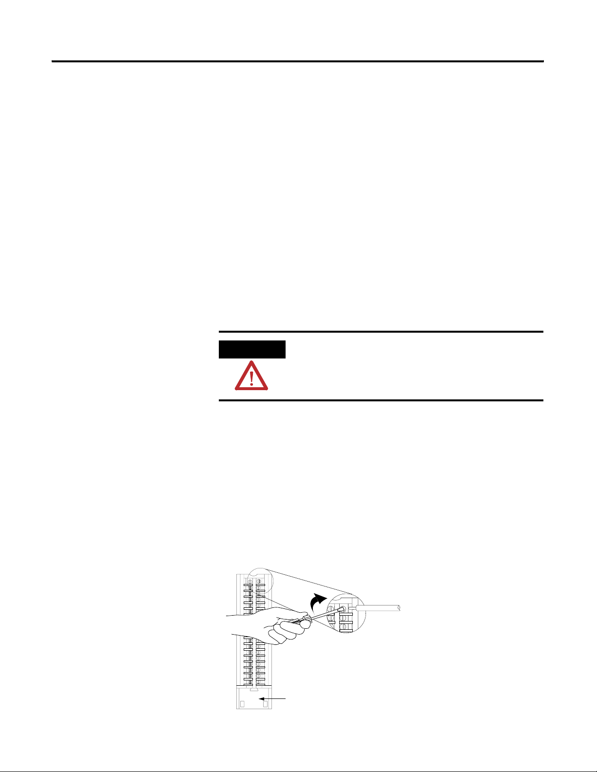
Removing the Removable Terminal Block
If you need to remove the module from the chassis, you must first
remove the RTB from the module.
ATTENTION
Shock hazard exists. If the RTB is removed from
the module while the field-side power is applied,
the module will be electrically live. Do not touch
the RTB’s terminals. Failure to observe this caution
may cause personal injury.
The RTB is designed to support Removal and
Insertion Under Power (RIUP). However, when
you remove or insert an RTB with field-side power
applied, unintended machine motion or loss of
process control can occur. Exercise extreme
caution when using this feature. It is recommended
that field-side power be removed before removing
the module.
1. Unlock the locking tab at the top of the module.
2. Open the RTB door using the bottom tab.
3. Hold the spot marked PULL HERE and pull the RTB off the
module.
IMPORTANT
Do not wrap your fingers around the entire door.
A shock hazard exists.
Publication 1756-UM528A-EN-P - April 2004
20855-M
Page 39

Installing the Sequence of Events Module 3-13
Removing the Module from the Chassis
1. Push in the top and bottom locking tabs.
Locking tabs
20856-M
2. Pull module out of the chassis.
20857-M
Publication 1756-UM528A-EN-P - April 2004
Page 40

3-14 Installing the Sequence of Events Module
Chapter Summary and What’s Next
In this chapter, you read about:
• installing the module.
• keying the RTB and IFM.
• connecting wiring.
• assembling the RTB and the housing.
• installing the RTB or IFM onto the module.
• removing the RTB from the module.
• removing the module from the chassis.
Chapter 4 explains Configuring the Sequence of Events Module.
Publication 1756-UM528A-EN-P - April 2004
Page 41

Chapter
4
Configuring the Sequence of Events Module
What This Chapter Contains
Configuring Your I/O Module
This chapter describes how to configure your Sequence of Events
module.
Table 4.1
For information on: See page:
Configuring Your I/O Module 4-1
Overview of the Configuration Process 4-2
Adding a New Module to Your RSLogix 5000 Project 4-3
Using the Default Configuration 4-6
Altering the Default Configuration 4-6
Downloading Configuration 4-7
Editing Configuration 4-7
Configuring Modules in a Remote Chassis 4-9
You must configure your module upon installation. The module
will not work until it has been configured with at least the default
configuration.
IMPORTANT
This chapter focuses on configuring I/O modules in
a local chassis. To configure I/O modules in a
remote chassis, you must follow all the detailed
procedures with two additional steps. To see the
additional steps, see page 4-9.
RSLogix 5000 Configuration Software
You must use RSLogix 5000, version 13 to set configuration for
your Sequence of Events module. You have the option of accepting
default configuration for your module or writing point level
configuration specific to your application.
Both options are explained in detail, including views of software
screens, in this chapter.
1 Publication 1756-UM528A-EN-P - April 2004
Page 42

4-2 Configuring the Sequence of Events Module
Overview of the Configuration Process
Click on the Next Button to
Set Specific Configuration
When you use the RSLogix 5000 software to configure a Sequence
of Events module, you must perform the following steps:
1. Add the new module to your RSLogix 5000 project.
2. Accept the default configuration or change it to specific
configuration for the module.
3. Edit configuration for a module when changes are needed.
Figure 4.1 shows an overview of the configuration process.
Figure 4.1
Select a:
• New module
• Major Revision
Configure the:
• Name
• Slot number
• Comm. format
• Minor revision
• Keying choice
Click on the Finish Button to
Use Default Configuration
Make custom
configuration
choices here
NEXT FINISH
Series of
Application
Specific
Screens
Configuration complete
Download
configuration to
owner-controller
Reconfigure module as needed via
series of screens or controller tags
41058
Publication 1756-UM528A-EN-P - April 2004
Page 43

Configuring the Sequence of Events Module 4-3
Adding a New Module to Your RSLogix 5000 Project
If you are not offline, use this
pull-down menu to go offline
After you have started RSLogix 5000 and created a controller, you
must add a new module to your project. The wizard allows you to
create a new module and write configuration. You can use default
configuration or write specific configuration for your application.
IMPORTANT
You must be offline when you create a new module.
1. If necessary, go offline.
A. Right-click on I/O
Configuration.
B. Select New Module
2. Add the Sequence of Events module to your
RSLogix 5000 project.
Publication 1756-UM528A-EN-P - April 2004
Page 44

4-4 Configuring the Sequence of Events Module
A. Select the
Sequence of
Events module.
B. Click OK.
3. When the Select Module Type screen appears, select the
Sequence of Events module.
4. Configure the module. The first screen of the configuration
wizard is shown below.
A. Name the module.
B. Select the module’s slot number.
C. Choose a Communications Format. For
more information, see page 4-5.
D. Make sure the Minor Revision number
matches your module’s minor revision.
E. Choose an Electronic Keying method. For
more information, see page 5-13.
F. If you are altering the default
configuration, click Next. Go to page 4-6.
G. If you are using default configuration,
click Finish. Go to page 4-6.
Publication 1756-UM528A-EN-P - April 2004
Page 45

Configuring the Sequence of Events Module 4-5
Communications Format
The communications format determines what operational mode
your Sequence of Events module uses and, consequently, what tags
RSLogix 5000 generates when configuration is complete. Once a
module is created, you cannot change the communications format
unless you delete and recreate the module.
Table 4.2 lists the communications formats used with input modules:
Table 4.2
If you want the Sequence of Events
module to operate in this mode
CST Per Point mode CST Per Point
FIFO mode CST FIFO Mode
choose this communication format:
For more information on the Sequence of Events module’s
operational modes, see page 5-3.
Electronic Keying
Electronic keying allows the ControlLogix system to control what
modules belong in the various slots of a configured system.
During module configuration, you must choose one of the
following keying options for your Sequence of Events module:
• Exact Match
• Compatible Module
• Disable Keying
For more information on electronic keying, see page 5-13.
Publication 1756-UM528A-EN-P - April 2004
Page 46

4-6 Configuring the Sequence of Events Module
Using the Default Configuration
Altering the Default Configuration
On this screen, you can:
A. Change the RPI. For more information
on the RPI, see page 2-6.
B. Inhibit the module. For more
information on inhibiting the module,
see page 5-15.
If you use the default configuration and click on Finish, you are done.
If you click Next in step 4 on page 4-4, you can write specific
configuration for your module in RSLogix 5000.
Some of the screens that appear during this initial module
configuration process are blank and are not shown here. However,
those screens can be important during online monitoring. To see
these screens in use, see Chapter 8, Troubleshooting the Sequence of
Events Module.
Write specific configuration for your Sequence of Events module
on the following screens.
C. Make sure a Major Fault occurs on
the module’s owner-controller if there
is a connection failure between the
module and the controller.
D. Click Next until you see the
screen below.
On this screen, you can:
A. Enable CST Capture for each input
point. For more information on CST
Capture, see page 5-5.
B. Configure Chatter Detection for each
input point. For more information on
Chatter Detection, see page 5-8.
C. Set the Input Filter Times. For more
information on Input Filters, see
page 5-10.
D. Click on the box to enable CST
Latching. For more information on CST
Latching, see page 5-7.
E. Click Finish.
Publication 1756-UM528A-EN-P - April 2004
Page 47

Configuring the Sequence of Events Module 4-7
Downloading Configuration
A. Click here to see the
pull-down menu.
B. Click download.
After you write configuration for your Sequence of Events module,
the module does not use this configuration until you download it to
the owner-controller. The download transfers the entire program to
the controller, overwriting any existing program.
Download module configuration as shown below.
Depending on your application, a variety of RSLogix 5000 screens
may appear to choose a path to your ControlLogix controller and to
verify the download. Navigate those screens as best fits
your application.
Editing Configuration
This completes the download process.
After you have set configuration for a module, you can review and
change your choices. You can change configuration data and
download it to the controller while online. This is called dynamic
reconfiguration.
Your freedom to change some configurable features, though,
depends on whether the controller is in Remote Run Mode or
Program Mode.
IMPORTANT
Although you can change configuration while
online, you must go offline to add or delete
modules from the project.
Publication 1756-UM528A-EN-P - April 2004
Page 48

4-8 Configuring the Sequence of Events Module
A. Right-click on the module.
B. Select Properties
The editing process begins on the main page of RSLogix 5000.
A. Click the tab where you need to
reconfigure the module.
In this example, CST Capture
was disabled for several input
points.
B. When the module is
reconfigured, click OK.
The General tab of the configuration wizard appears. Click on the
tab of the page that you want to view or reconfigure and make any
appropriate changes.
Make any necessary changes as shown in the example below.
Publication 1756-UM528A-EN-P - April 2004
Page 49

Configuring the Sequence of Events Module 4-9
Configuring Modules in a Remote Chassis
ControlLogix ControlNet Interface modules (1756-CNB or
1756-CNBR) or the EtherNet/IP Bridge module (1756-ENBT) are
required to communicate with Sequence of Events modules in a
remote chassis.
You must configure the communications module in the local
chassis and the remote chassis before adding remote Sequence of
Events modules to your project.
1. Add a communications module to the local chassis.
A. Right-click on I/O Configuration.
B. Select New Module
2. Choose a communications module (1756-CNB, 1756-CNBR or
1756-ENBT) for the local chassis.
3. Configure the communications module in the local chassis.
For more information on the ControlLogix ControlNet
Interface modules, see the Using ControlNet Communication
Modules in Logix5000 Control Systems user manual,
publication CNET-UM001.
For more information on the ControlLogix EtherNet/IP Bridge
module, see the Using EtherNet/IP Communication Modules
in Logix5000 Control Systems user manual, publication
ENET-UM001.
Publication 1756-UM528A-EN-P - April 2004
Page 50

4-10 Configuring the Sequence of Events Module
A. Right-click on the local
communication module.
B. Select New Module
4. Add a communications module to the remote chassis.
A. Right-click on the remote
communication module.
B. Select New Module
5. Select a communications module for the remote chassis.
6. Configure the communications module in the remote chassis.
7. Add a Sequence of Events module to the remote chassis.
Publication 1756-UM528A-EN-P - April 2004
8. Configure the new Sequence of Events module as described
earlier in this chapter.
Page 51

Configuring the Sequence of Events Module 4-11
Chapter Summary and What’s Next
In this chapter, you read about configuring your Sequence of Events
module.
Chapter 5 describes Using the Sequence of Events Module Features.
Publication 1756-UM528A-EN-P - April 2004
Page 52

4-12 Configuring the Sequence of Events Module
Notes:
Publication 1756-UM528A-EN-P - April 2004
Page 53

Using the Sequence of Events
Module Features
Chapter
5
What This Chapter Contains
This chapter describes the features available on the Sequence of
Events module.
Table 5.1
For information on: See page:
Determining Module Compatibility 5-2
Two Operational Modes 5-3
Enable CST Capture 5-5
Latch CST 5-7
Chatter Detection 5-8
Software Configurable Input Filters 5-10
Electronic Keying 5-13
Module Inhibiting 5-15
Removal and Insertion Under Power (RIUP) 5-16
Module Fault Reporting 5-16
Fully Software Configurable 5-17
Producer/Consumer Model 5-17
Status Indicator Information 5-18
Full Class I Division 2 Compliance 5-19
Agency Certifications 5-19
1 Publication 1756-UM528A-EN-P - April 2004
Page 54

5-2 Using the Sequence of Events Module Features
Determining Module Compatibility
Primarily, a Sequence of Events module is used to timestamp input
data. However, additionally, the module interfaces to sensing
devices and detects whether they are ON or OFF. The module also
converts ON/OFF signals from user devices to appropriate logic
level for use in the processor. Typical input devices include:
• auxiliary contacts
• limit switches
When designing a system using Sequence of Events modules, you
must consider:
• the voltage necessary for your application
• whether you need a solid state device
• current leakage
• if your application should use sinking or sourcing wiring.
For more information on compatibility of other Rockwell
Automation products to Sequence of Events modules, see the I/O
Systems Overview, publication CIG-SO001.
There are two types of features available on the Sequence of
Events module:
• Module Features That Can Be Configured - Features that can be
adjusted to make sure the module operates as efficiently as
possible in your application (e.g., input filter times)
• Other Inherent Module Features - Features that cannot be
changed but are still crucial to module functionality (e.g.,
producer/consumer model)
Publication 1756-UM528A-EN-P - April 2004
Page 55

Using the Sequence of Events Module Features 5-3
Module Features That Can Be Configured
Table 5.2 lists features on the Sequence of Events module that can
be configured.
Table 5.2
This feature: is described on:
Two Operational Modes 5-3
Enable CST Capture 5-5
Chatter Detection 5-8
Software Configurable Input Filters 5-10
Latch CST 5-7
Electronic Keying 5-13
Module Inhibiting 5-15
Two Operational Modes
The Sequence of Events module can operate in either of the modes
described in Table 5.3:
Table 5.3
Operational mode: Description:
CST Per Point Mode The module produces timestamps for up to 2 input
transitions per input, one for OFF to ON transitions
and another for ON to OFF transitions; these
timestamps can occur simultaneously. This is the
default setting when you add the module to an
RSLogix 5000 project.
First In First Out (FIFO) Mode The module timestamps an unlimited number of input
transitions, regardless of direction (i.e., either OFF to
ON or ON to OFF) or input (i.e., the same input can
transition many times and the module will timestamp
every transition) and stores them in an on-board
buffer.
The module is capable of storing the data for up to
160 input transitions in its on-board buffer at a single
time. However, if you retrieve data from the buffer
effectively (i.e., retrieve the data before the module
timestamps greater than 160 input transitions), the
module can timestamp an infinite number of input
transitions.
We recommend you use this mode if you want to
minimize propagation delay of new input data being
reported to the controller. For more information on
propagation delay, see page 2-4.
Publication 1756-UM528A-EN-P - April 2004
Page 56

5-4 Using the Sequence of Events Module Features
During initial module configuration, you must choose a
communication format for the module. The communication format
determines the mode in which your module operates. The example
screen below shows how to choose your module’s communication
format and, thus, operational mode.
Use this pull-down menu to
choose a communication format.
IMPORTANT
Once the module is created in your RSLogix 5000
project, you cannot change the communications
format without deleting the module from the project
and recreating it.
For more information on using the Sequence of Events module in
CST Per Point mode, see Chapter 6.
For more information on using the Sequence of Events module in
FIFO mode, see Chapter 7.
Publication 1756-UM528A-EN-P - April 2004
Page 57

Using the Sequence of Events Module Features 5-5
Enable CST Capture
Enable CST Capture instructs the Sequence of Events module to
timestamp specific input points transitions. You can use this feature
to instruct the module to capture the CST when the inputs
transition from:
• OFF to ON only
• ON to OFF only
or
• both OFF to ON and ON to OFF
When Enable CST Capture is enabled for specific points and
transitions occur for those points, the Sequence of Events
module not only captures the CST at the transition
occurrence but also sends input data to the controller.
IMPORTANT
All points on the Sequence of Events module have
Enable Capture CST enabled by default for both
ON to OFF and OFF to ON transitions.
Additionally, you must specify an RPI regardless of
whether you use Enable Capture CST on any input
points. If a change does not occur within the RPI
timeframes, the module will still multicast data at
the rate specified by the RPI.
Publication 1756-UM528A-EN-P - April 2004
Page 58

5-6 Using the Sequence of Events Module Features
Use the Configuration tab in RSLogix 5000 to set Enable CST
Capture, as shown in the example below.
Click the Configuration tab.
• Click on the individual boxes for
each input point to enable CST
Capture for that point.
• Clear the individual boxes for
each input point to disable CST
Capture for that point.
You can also use these boxes to enable
or disable all points simultaneously.
IMPORTANT
The basic function of Enable CST Capture (i.e.,
timestamp specific input transitions) occurs
whether the Sequence of Events module is used in
CST Per Point mode or FIFO mode. However, how
the module uses the data from each transition
varies slightly depending on the mode in which
the module is operating.
• For more information on how Enable CST
Capture is used in CST Per Point mode, see
page 6-7.
• For more information on how Enable CST
Capture is used in FIFO mode, see page 7-9.
Publication 1756-UM528A-EN-P - April 2004
Page 59

Using the Sequence of Events Module Features 5-7
Latch CST
Latch CST can be used to prevent the Sequence of Events module
from overwriting input data once it is timestamped.
• If Latch CST is enabled, the module only timestamps a
specific number of input transitions(e.g., the first transition in
CST Per Point mode) and ignores future input transitions (at
least until the controller clears the timestamp data already
received, as described on page 6-12 and page 7-20).
• If Latch CST is disabled, the module timestamps every input
transition and may overwrite previously recorded
timestamp data if the controller does not acknowledge the
data quickly enough.
This feature is set on a module-wide basis and is enabled
by default.
Click this box to enable the
Latch CST feature.
IMPORTANT
The bullets above provide a general description of
how Latch CST works. However, there are slight
differences between how the features affects
module behavior in each operational mode.
• For more information on how Latch CST is used
in CST Per Point mode, see page 6-7.
• For more information on how Latch CST is used
in FIFO mode, see page 7-9.
Use the Configuration tab in RSLogix 5000 to enable Latch CST, as
shown in the example below.
Unclick the box to disable
the feature.
Publication 1756-UM528A-EN-P - April 2004
Page 60

5-8 Using the Sequence of Events Module Features
Chatter Detection
To detect a faulty input device wired to the Sequence of Events
module, the module can use Chatter Detection to detect a
chattering signal from a device connected to one of its inputs (e.g.,
rapid transitions from a failed contact) and ignore the data. If not
accounted for, chatter can cause the module to timestamp invalid
input transitions. Typically, chattering signals cause inputs to
transition falsely many times in a relatively short period of time.
To configure Chatter Detection for an input, you must define an
acceptable number of input transitions within a specific
time period.
• If the number of input transitions meets the number specified in
the configured time period, the module considers the point in
chatter, the input device defective and ignores the last transition
(i.e., clears any timestamp data for the transition from its buffer)
and all subsequent transitions while still chattering.
• If the number of events in the specific time is less than your
defined number, the input will not go into chatter and
timestamps are produced for all transitions.
• If an input is chattering, the corresponding fault bit for that
input is set.
• Once a point is in chatter, all transitions on that input are
ignored until the point is no longer chattering; an input is no
longer chattering if the configured chatter time elapses and no
new transitions occur on the input.
Publication 1756-UM528A-EN-P - April 2004
Page 61

A. Type the number of events.
Range is 2-127 events. Use 0
to disable this feature.
B. Type the time (measured in
milliseconds). You can use up
to 10,000 milliseconds.
In this example, if 5 events
occur on input point 0 within
any 20ms time frame, the
module considers the point to
be chattering.
Using the Sequence of Events Module Features 5-9
Use the Configuration tab in RSLogix 5000 to configure Chatter
Detection, as shown in the example below.
IMPORTANT
When configuring Chatter Detection, make sure
the time divided by the number of events is greater
than the module’s input filter times. For example,
in the example above the time (20ms) divided by
the number of events (5) = 4. For Chatter
Detection to work properly in this case, make sure
your input filter < 4ms.
Publication 1756-UM528A-EN-P - April 2004
Page 62

5-10 Using the Sequence of Events Module Features
Software Configurable Input Filters
To account for hard contact “bounce”, you can configure ON to
OFF and OFF to ON input filter times in RSLogix 5000 for your
Sequence of Events module. These filters define how long an
input transition must remain in the new state before the
module considers the transition valid.
IMPORTANT
Input filters are applied to all inputs on the
Sequence of Events module. You cannot apply
input filters to individual inputs on the module.
When an input transition occurs, the Sequence of Events module
timestamps the transition on the initial edge of the transition and
stores data for the transition on-board; the module then scans the
input where the transition occurred every 25µs for the length of the
filter time setting to verify that the input remains in the new state
(i.e., remained OFF or ON).
• If the input remains in the new state for a time period equal to
the filter time setting, the module sends data for the transition to
the controller.
• If the input changes state again (i.e., returns to the original
state) before the length of time of the filter setting has
elapsed, the module continues to scan that input for up to 4x
the filter setting. During this continued scan period, one of
the following events occurs:
– At some point in the time period that is 4x the length of the
input filter setting, the input returns to the transitioned state
and remains there for a length of time equal to the filter
setting. In this case, the module sends data from the
transition to the controller.
– The input does not remain in the transitioned state for a
time period equal to the filter setting at any point in the
time period that is 4x the length of the input filter setting.
In this case, the module does not consider the original
transition valid and drops the timestamp.
Publication 1756-UM528A-EN-P - April 2004
See Figure 5.1 on page 5-11 for an example of how the Sequence of
Events module’s input filters operate.
Page 63

Input turns ON;
timestamp recorded
Using the Sequence of Events Module Features 5-11
In the example, a Sequence of Events module:
• is Enable CST Capture-enabled for all of its points
• uses a 2ms input filter setting for OFF to ON transitions
Three possible scenarios can result after an input transitioning from
OFF to ON in the given circumstances.
• Scenario #1 (no bounce) – The input turns ON and remains
for the full 2ms. In this case, the module considers the
transition valid and sends the data recorded at the transition
to the controller.
Figure 5.1
Input remains ON for at least 2ms; transition is considered
valid and the timestamp is sent to the controller
Input turns ON;
timestamp recorded
012345678
Time in milliseconds
43671
• Scenario #2 – The input turns ON but turns OFF before 2ms
(length of the input filter setting) elapses. In this case, the
Sequence of Events module continues to scan the input every
25µs for 4x the length of the input filter setting (i.e., for 8ms).
At some point in those 8ms, the input turns ON again and
remains for at least 2ms (i.e., the input filter setting). In this
case, the module considers the transition valid and sends the
data timestamped at the original transition to the controller.
Figure 5.2
Input turns OFF before
2ms have elapsed.
Input turns ON and remains ON for at
least 2ms in the time period that is 4x the
input filter setting (i.e., 8ms).
The module sends the timestamp
recorded at the original transition point to
the controller.
012345678
Time in milliseconds
43672
Publication 1756-UM528A-EN-P - April 2004
Page 64

5-12 Using the Sequence of Events Module Features
Figure 5.3
• Scenario #3 – The input turns ON but turns OFF before 2ms
(length of the input filter setting) elapses. In this case, the
Sequence of Events module continues to scan the input every
25µs for 4x the length of the input filter setting (i.e., for 8ms).
In those 8ms, the input never remains ON for at least 2ms
(i.e., the input filter setting). In this case, the module
considers the transition invalid and drops the data
timestamped at the original transition.
Input turns ON;
timestamp #1
43671
Type the filter times or use the
increase/decrease arrows to
configure the Input Filter Time.
Input turns OFF before
2ms have elapsed.
012345678
Time in milliseconds
In none of these time periods is
the input ON for at least 2ms
Use the Configuration tab in RSLogix 5000 to configure Input
Filters, as shown in the example below.
After 8ms (i.e., 4x the input filter setting),
the module drops the data recorded at the
original transition. If an RPI occurs during
this 8ms, the module sends the controller its
current valid input data; the data that’s sent
does not include data from the transition
describes in this graphic because the
timestamp has not been validated.
The next time the input turns ON, the
module records the transition as
timestamp #1.
The Input Filter Time range is 0
to 50ms.
Publication 1756-UM528A-EN-P - April 2004
Page 65

Using the Sequence of Events Module Features 5-13
Electronic Keying
Instead of plastic mechanical backplane keys, electronic keying
allows the ControlLogix system to control what modules belong in
the various slots of a configured system.
During module configuration, you must choose one of the
following keying options for your Sequence of Events module:
• Exact Match
• Compatible Module
• Disable Keying
When the controller attempts to connect to and configure a
Sequence of Events module (e.g. after program download), the
module compares the following parameters before allowing the
connection and configuration to be accepted:
• Vendor
• Product Type
• Product Code
• Major Revision - Change that affects the module’s function or
RSLogix 5000 interface
• Minor Revision - Change that does not affect the module’s
intended function or RSLogix 5000 interface
The comparison is made between the keying information present
in the module and the keying information in the controller’s
program, preventing the inadvertent operation of a system with the
wrong module in the wrong slot. For example, if you select Exact
Match and a module with revision 1.2 is placed in a location
configured for a module with revision 1.4, the controller does not
make a connection to the new module because of the mismatched
revisions.
Publication 1756-UM528A-EN-P - April 2004
Page 66

5-14 Using the Sequence of Events Module Features
Table 5.4 describes the keying options available with your module.
Table 5.4
Keying option: Definition:
Exact Match All of the parameters listed above must match or the inserted module will reject a connection to the
controller.
Compatible Module The Compatible Match mode allows a Sequence of Events module to determine whether it can emulate the
module defined in the configuration sent from the controller. With Sequence of Events modules, the module
can emulate older revisions. The module will accept the configuration if the configuration’s major.minor
revision is less than or equal to the physical module’s revision.
For example, if the configuration contains a major.minor revision of 1.7, the module inserted into the slot must
have a firmware revision of 1.7 or higher for a connection to be made. When a module is inserted with a
major.minor revision that is less than the revision for which the slot is configured (i.e., the module has a
revision of 1.6 and the slot is configured for a module with revision 1.8), no connection is made between the
controller and the I/O module.
TIP
We recommend using Compatible Match whenever possible. Remember, though, with
major revision changes, the module only works to the level of the configuration.
At the time of this printing, the Sequence of Events module uses a major revision
(1)
of 1.3
However, if a new major revision for the module is released, consider this
example. If a slot is configured for a module with major.minor revision of 1.7 and you
insert a module with a major.minor revision of 2.3, the module works at the 1.7 level,
with respect to module functions that are related to RSLogix 5000 such as interface
changes. Bug fixes that are affected by the module’s firmware, though, would work at
the 2.3 revision level.
If possible, we recommend that you make sure configuration is updated to match the
revision levels of all I/O modules, including your Sequence of Events module. Failure to
do so may not prevent the application from working but may defeat the purpose of
upgrading your modules’ revision levels.
Disable Keying The inserted module attempts to accept a connection to the controller regardless of its type.
ATTENTION
Be extremely cautious when using the disable keying option; if used incorrectly, this
option can lead to personal injury or death, property damage or economic loss.
If keying is disabled, a controller makes a connection with most modules of the same type as that used in the
slot configuration. For the ControlLogix Sequence of Events module, if keying is disabled, the controller will
only make a connection to another Sequence of Events module.
A controller will NOT establish a connection if any of the following conditions exist, even if keying is disabled:
• The slot is configured for one module type (e.g. input module) and a module of another type (e.g. output
module) is inserted in the slot.
• The module inserted into the slot cannot accept some portion of the configuration. For example, if a
Sequence of Events module is inserted into a slot configured for a diagnostic input module, the
controller cannot make a connection because the module will not accept/process the diagnostic
configuration.
(1)
Minor revisions are incremented by single counts such that minor level 10 (i.e., major.minor revision level = 1.10) follows minor revision level 9 (i.e., 1.9).
Publication 1756-UM528A-EN-P - April 2004
Page 67

Using the Sequence of Events Module Features 5-15
Module Inhibiting
With module inhibiting, you can indefinitely suspend a connection
between an owner-controller and a Sequence of Events module.
This process can occur in the following way:
• You write configuration for a Sequence of Events module but
inhibit the module to prevent it from communicating with the
owner-controller. In this case, the owner-controller does not
establish a connection and configuration is not sent to the
module until the connection is uninhibited.
The following examples are instances where you may need to use
module inhibiting:
• You want to FLASH upgrade your module. We recommend
you:
a. Inhibit the module.
b. Perform the upgrade.
c. Uninhibit the module.
Click on this box to inhibit
or uninhibit the module
• You are using a program that includes a module that you do
not physically possess yet, but you do not want the controller
to continually look for a module that does not exist yet. In
this case, you can inhibit the module in your program until it
physically resides in the proper slot.
You can inhibit your Sequence of Events module on the
Connection tab in RSLogix 5000, as shown in the example below.
Publication 1756-UM528A-EN-P - April 2004
Page 68

5-16 Using the Sequence of Events Module Features
Other Inherent Module Features
Table 5.5 lists features on the Sequence of Events module that cannot
be configured.
Table 5.5
This feature: is described on:
Removal and Insertion Under Power (RIUP) 5-16
Module Fault Reporting 5-16
Fully Software Configurable 5-17
Producer/Consumer Model 5-17
Status Indicator Information 5-18
Full Class I Division 2 Compliance 5-19
Agency Certifications 5-19
Removal and Insertion Under Power (RIUP)
The Sequence of Events module is designed to be installed or
removed while chassis power is applied.
WARNING
Repeated electrical arcing causes excessive wear to contacts on both
the module and its mating connector. Worn contacts may create
electrical resistance that can affect module operation.
When you insert or remove the module while
backplane power is on, an electrical arc can occur.
This could cause an explosion in hazardous
location installations. Be sure that power is
removed or the area is nonhazardous before
proceeding.
Module Fault Reporting
Your Sequence of Events module provides both a hardware and
software indication when a module fault occurs. The module’s status
indicator and RSLogix 5000 graphically display each fault and include
a fault message describing the nature of the fault.
This feature allows you to determine how the fault affects your
module and what action you should take to resume normal operation.
For more information on how to use hardware and software indicators
when a module fault occurs, see Chapter 8, Troubleshooting the
Sequence of Events Module.
Publication 1756-UM528A-EN-P - April 2004
Page 69

Using the Sequence of Events Module Features 5-17
Fully Software Configurable
RSLogix 5000 uses a custom, easily understood interface to write
configuration. All module features are enabled or disabled through
the I/O configuration portion of the software.
You can also use the software to interrogate your Sequence of
Events module to retrieve:
• serial number
• revision information
• product code
• vendor identification
• error/fault information
• diagnostic counters.
By eliminating such tasks as setting hardware switches and
jumpers, the software makes module configuration easier and more
reliable.
Producer/Consumer Model
By using the Producer/Consumer model, Sequence of Events
modules can produce data without having been polled by a
controller first. The module produces the data and the
owner-controller device consumes it.
Publication 1756-UM528A-EN-P - April 2004
Page 70

5-18 Using the Sequence of Events Module Features
Status Indicator Information
Each Sequence of Events module has LED status indicators on the
front of the module that allows you to check the module health and
operational status. Table 5.6 describes the module’s LED
status indicators:
Table 5.6
Status: Description:
I/O status
(ST LEDs)
Module status
(OK LED)
The LED status indicators used on the Sequence of Events module
are shown in Figure 5.4.
This yellow display indicates the ON/OFF state of the field device.
This red/green display indicates the module’s communication/module
health status.
Figure 5.4
20945
For more information on how to use the Sequence of Events
module’s LED status indicators, and RSLogix 5000, when
troubleshooting your application, see Chapter 8, Troubleshooting the
Sequence of Events Module.
Publication 1756-UM528A-EN-P - April 2004
Page 71

Using the Sequence of Events Module Features 5-19
Full Class I Division 2 Compliance
The Sequence of Events module maintains CSA Class I Division 2
system certification. This allows the ControlLogix system to be
placed in an environment other than only a 100% hazard free.
Chapter Summary and What’s Next
IMPORTANT
Modules should not be pulled under power, nor
should a powered RTB be removed, in a Class I
Division 2 environment.
Agency Certifications
The Sequence of Events module is marked for any agency
certifications (e.g. UL, CSA, CE, FM and C-Tick) it has obtained. See
the module’s label for all agency certifications.
In this chapter, you read about using the Sequence of Events
module’s features. Chapter 6 describes the Using The Sequence of
Events Module in CST Per Point Mode.
Publication 1756-UM528A-EN-P - April 2004
Page 72

5-20 Using the Sequence of Events Module Features
Notes:
Publication 1756-UM528A-EN-P - April 2004
Page 73

Chapter
Using The Sequence of Events Module in
CST Per Point Mode
6
What This Chapter Contains
Overview of the Mode
This chapter describes how to use the Sequence of Events module
in CST Per Point mode.
Table 6.1
For information on: See page:
Overview of the Mode 6-1
What Are The Typical Applications Where CST Per Point Mode is
Used?
Configuring the Module for CST Per Point Mode 6-4
Managing the Data in CST Per Point Mode 6-8
Module Sends Data to the Controller 6-8
Copying Relevant Input Data to a Separate Data Structure 6-10
Acknowledging Latched Timestamp Data 6-12
Sorting the Data 6-14
Clearing All Data From the Module’s Buffers At Once 6-14
In CST Per Point mode, the Sequence of Events module can be
configured to timestamp two transitions per input, one in each
direction (OFF to ON and ON to OFF).
6-4
When specific points that are Enable CST Capture-enabled
transition (e.g., input 1 is configured so that Enable CST Capture is
enabled for OFF to ON transitions and the input turns ON), the
module timestamps the transition with the current CST value on the
backplane. The module produces data for the owner-controller when
the input filter and chatter detection criteria have been met and at
subsequent RPIs.
1 Publication 1756-UM528A-EN-P - April 2004
Page 74

6-2 Using The Sequence of Events Module in CST Per Point Mode
How Does the Module Store Timestamp Data in CST Per Point Mode?
The module is installed, wired to input
devices and ready to begin operation. All
inputs are configured to timestamp any
transition that occurs.
At this point, timestamp data for each
input is 0 because no input transitions
have occurred.
Note that only 8 bits of the 64-bit CST
timestamp are shown.
With each timestamped transition, the Sequence of Events module
stores data for that point. An overview of how the module stores
timestamp data in CST Per Point mode is shown in Figure 6.1:
Figure 6.1
Input 0
Input 1
Input 2
Input 15
0 0 0 0 0 0 0
0 0 0 0 0 0 0
0 0 0 0 0 0 0
0 0 0 0 0 0 0
0 0 0 0 0 0 0
0 0 0 0 0 0 0
0 0 0 0 0 0 0
0 0 0 0 0 0 0
OFF/ON timestamp data
ON/OFF timestamp data
OFF/ON timestamp data
ON/OFF timestamp data
OFF/ON timestamp data
ON/OFF timestamp data
OFF/ON timestamp data
ON/OFF timestamp data
Input 1 transitions from OFF to ON.
The module timestamps the transition;
the module sends the data to the
owner-controller (not shown) and also
stores it locally.
Input 2 transitions from ON to OFF.
The module timestamps the transition;
the module sends the data to the
owner-controller (not shown) and also
stores it locally.
Note that the module continues to store
the timestamp for the OFF to ON
transition on input 1.
Input 0
Input 1
Input 2
Input 15
Input 0
Input 1
Input 2
Input 15
0 0 0 0 0 0 0
0 0 0 0 0 0 0
0 1 0 1 1 0 0
0 0 0 0 0 0 0
0 0 0 0 0 0 0
0 0 0 0 0 0 0
0 0 0 0 0 0 0
0 0 0 0 0 0 0
0 0 0 0 0 0 0
0 0 0 0 0 0 0
0 1 0 1 1 0 0
0 0 0 0 0 0 0
0 0 0 0 0 0 0
1 1 0 0 1 0 1
0 0 0 0 0 0 0
0 0 0 0 0 0 0
OFF/ON timestamp data
ON/OFF timestamp data
OFF/ON timestamp data
ON/OFF timestamp data
OFF/ON timestamp data
ON/OFF timestamp data
OFF/ON timestamp data
ON/OFF timestamp data
OFF/ON timestamp data
ON/OFF timestamp data
OFF/ON timestamp data
ON/OFF timestamp data
OFF/ON timestamp data
ON/OFF timestamp data
OFF/ON timestamp data
ON/OFF timestamp data
43793
Publication 1756-UM528A-EN-P - April 2004
Page 75

Using The Sequence of Events Module in CST Per Point Mode 6-3
When the Sequence of Events module operates in CST Per Point
mode, generally the following occurs:
1. You configure the Sequence of Events module to operate in
CST Per Point mode via the Communication Format selection.
2. The Sequence of Events module timestamps each transition
for inputs that are Enable CST Capture-enabled. The module can
timestamp each transition with a unique CST with 25µs
resolution.
3. The module sends all of its input data, including the new data
from the most recent transition, to the controller immediately
after timestamping the transition and passing the input filter to
make sure the transition was valid.
4. You copy new data from the controller tags to a separate data
structure for later sorting.
5. Once the data is copied to a separate data structure, you may
sort the data in the controller to determine the order of events.
Some of these typical events are described in greater detail in the
rest of this chapter.
Publication 1756-UM528A-EN-P - April 2004
Page 76

6-4 Using The Sequence of Events Module in CST Per Point Mode
What Are The Typical Applications Where CST Per Point Mode is Used?
Configuring the Module for CST Per Point Mode
CST Per Point mode is typically used in applications that need to
determine relative first fault detection after an event cascade occurs.
The Sequence of Events module can provide unique timestamps for
separate input transitions as long as they occur 25µs apart; you can
sort the data resulting from an event cascade to determine where the
first input transition occurred in the cascade.
You can also use the 1756HP-GPS module to give the stored CST
timestamps a real-time reference. For more information on how to
integrate the 1756HP-GPS module into your ControlLogix Sequence of
Events system, see Appendix B.
The following are example typical applications for CST Per
Point mode:
• Substation automation
• Load-shedding/energy management
• Emergency shutdown systems
You configure the same general set of configurable features
(described in Chapter 5) whether you are using the Sequence of
Events module in CST Per Point mode or FIFO mode. However, for
some features, the module behavior as dictated by the feature,
varies according to operational mode. For example, Latch CST
impacts the Sequence of Events module behavior slightly
differently in CST Per Point mode than in FIFO mode.
Publication 1756-UM528A-EN-P - April 2004
You should be aware of the impact the following configurable
features have on module behavior in CST Per Point mode:
• Communications Format
• Latch CST
• Enable CST Capture
• Universal Coordinated Time (UCT)
Page 77

Use this pull-down menu to
choose the CST Per Point
communication format.
Using The Sequence of Events Module in CST Per Point Mode 6-5
Choosing a Communications Format
During initial module configuration, you must choose a
communication format for the module. The communications format
determines what operational mode your Sequence of Events
module uses and, consequently, what tags RSLogix 5000 generates
when configuration is complete.
To operate the Sequence of Events module in CST Per Point mode,
you must choose the CST Per Point communication format, as
shown below.
Publication 1756-UM528A-EN-P - April 2004
Page 78

6-6 Using The Sequence of Events Module in CST Per Point Mode
Using Latch CST in CST Per Point Mode
When enabled, Latch CST prevents the Sequence of Events module
from overwriting recorded timestamp data once a transition occurs.
This feature is set on a module-wide basis and is enabled by
default. Table 6.2 describes how Latch CST affects the module in CST
Per Point mode.
Table 6.2
If Latch CST is
the following occurs
(1)
:
Enabled The Sequence of Events module timestamps two transitions for each input–one for OFF to ON and one for ON to OFF. If
similar transitions occur on inputs where a transition has already been timestamped and the data was not yet
acknowledged (for more information on acknowledging data, see page 6-12), the module does not timestamp the new
transition.
When transitions occur that the Sequence of Events module does not timestamp, the module sets the I.EventOverflow
tag for that point to inform the controller that an input transitioned but a timestamp was not produced for the transition.
Typically, Latch CST is enabled in CST Per Point mode.
Disabled The Sequence of Events module timestamps each transition for each input as it occurs. In this case, when multiple
transitions occur in the same direction on the same input, the module records the new timestamp data, overwriting any
previously-recorded data which had yet to be acknowledged (for more information on acknowledging data, see
page 6-12).
When the Sequence of Events module overwrites data, it sets the I.EventOverflow tag for that point to inform the
controller that events have been overwritten.
(1)
This table assumes the transition occurs on inputs that have Enable CST Capture enabled. If Enable CST Capture is disabled, the module does not timestamp transitions on
that input and, therefore, Latch CST does not affect module behavior.
IMPORTANT
We suggest you monitor the I.EventOverflow bits to
make sure you are aware of when transitions were
either not timestamped or when timestamp data
was overwritten.
Click this box to enable the
Latch CST feature.
Clear the box to disable
the feature.
Publication 1756-UM528A-EN-P - April 2004
Use the Configuration tab in RSLogix 5000 to enable Latch CST, as
shown in the example below.
Page 79

Using The Sequence of Events Module in CST Per Point Mode 6-7
Using Enable CST Capture in CST Per Point Mode
Regardless of operating mode, Enable CST Capture causes the
Sequence of Events module to timestamp specific input transitions.
However, keep the following in mind when using this feature in CST
Per Point mode:
• Typically, Latch CST is enabled in CST Per Point mode. The
configuration of this feature (described on page 6-6) determines
whether the module timestamps only the first transition on an
input or every transition on an input.
• If Latch CST is enabled, the module timestamps only the initial
transitions (OFF to ON and ON to OFF) for each input.
• Whenever an input transition is timestamped as a valid
transition, the module sends updated input data for all inputs to
the controller immediately and at every subsequent RPI.
Click the Configuration tab.
• Click on the individual boxes for
each input point to enable CST
Capture for that point.
• Clear the individual boxes for
each input point to disable CST
Capture for that point.
You can also use these boxes to enable
or disable all points simultaneously.
Use the Configuration tab in RSLogix 5000 to set Enable CST Capture,
as shown in the example below.
Publication 1756-UM528A-EN-P - April 2004
Page 80

6-8 Using The Sequence of Events Module in CST Per Point Mode
Managing the Data in CST Per Point Mode
In CST Per Point Mode, the Sequence of Events module sends all of its
input data to the controller immediately after an input transition has
been timestamped and at each RPI. You must manage the data coming
from the Sequence of Events module.
The following occurs in the process of the managing data coming
from the Sequence of Events module in CST Per Point mode:
1. The Sequence of Events module sends data to the controller.
2. The controller copies the relevant portions of the input data
to a separate array.
3. At the user’s discretion, the controller clears latched
timestamp data from the Sequence of Events module via the
O.EventAck and O.NewData tags, preparing the module to
timestamp the next transition.
This process is described in the rest of this section.
Module Sends Data to the Controller
1. Input 2 transitions
from OFF to ON.
42793
Figure 6.2 shows an example of the Sequence of Events module
sending data to the controller. In the example, the following occurs:
1. Input 1 transitions from OFF to ON. (The input has Enable CST
Capture enabled.)
2. The Sequence of Events module timestamps the transition.
3. The module sends its input data, including the transition
timestamp from input 1, to the controller.
Figure 6.2
Sequence of Events module ControlLogix controller
2. Module timestamps
the transition.
0 0 0 0 0 0 0
0 0 0 0 0 0 0
0 1 0 1 1 0 0
0 0 0 0 0 0 0
0 0 0 0 0 0 0
0 0 0 0 0 0 0
0 0 0 0 0 0 0
0 0 0 0 0 0 0
3. Module sends input
data to the controller.
I.Fault
I.Data
I.NewData
I.EventOverlow
I.ReturningUCTTime
I.EventNumber
I.Timestamp[16].OffOn[2]
I.Timestamp[16].OnOff[2]
Publication 1756-UM528A-EN-P - April 2004
Page 81

Table 6.3 Input Tags in CST Per Point Mode
Using The Sequence of Events Module in CST Per Point Mode 6-9
Table 6.3 describes the data that is sent for each input. These tags are
sent to the controller immediately after the module timestamps a
transition on any input and at each RPI.
Tag name: Set on a Per Point or
Modulewide basis:
I.Fault
I.Data
I.NewData
Per point
Per point
Per point
(1)
(1)
(1)
Description:
Indicates if a fault has occurred for the input.
0 = no fault
1 = fault – The fault can be chatter or communication fault as described below:
• Chatter - The Sequence of Events module can detect chatter on individual inputs
and will set the appropriate tag to 1 when chatter exists on an input. For
example, if the module has detected chatter on input 4, I.Fault.4 = 1.
• Communication fault - The controller sets this tag to 1 for all 32 bits if a
communication fault occurs on the module.
This tag clears when the fault that causes the condition no longer exists.
Status of the input point. This data is filtered if the Input Filter feature is used on the
module. Thus, an input change must pass through the filter before it is seen in this tag.
0 = input is OFF
1 = input is ON
For example, if input 3 is ON, I.Data.3 = 1.
Flag indicating if new timestamp data was detected on the input.
0 = no new timestamp data on the input
1 = new timestamp data on the input (since last acknowledged)
Because input data for all inputs is sent immediately after each timestamped transition
and at each RPI, this tag is useful to quickly determine on which input the transition
occurred. For example, if the Sequence of Events module sends new input data to the
owner-controller and I.NewData.5 = 1, you know that at least one of the timestamps for
input 5 (i.e., I.Timestamp[5].OffOn or I.Timestamp[5].OnOff) has new data.
I.EventOverflow
Per point
This tag only clears when the controller acknowledges the new data or all events on the
module are reset. For more information, see page 6-12.
(1)
Set for an input when the module either:
• Does not timestamp a transition on the input – The module has Latch CST
enabled and a similar transition has already been timestamped on this input but
has not been cleared via the EventAck and NewDataAck output tags (see
page 6-12).
or
• Overwrites previously-recorded timestamp data for the input – The module has
Latch CST disabled and multiple transitions occur on the input. In this case,
timestamp data from new transitions are recorded before previously-recorded
transitions were cleared from the input via the EventAck and NewDataAck
output tags (see page 6-12).
This value is cleared if the module is reset.
Publication 1756-UM528A-EN-P - April 2004
Page 82

6-10 Using The Sequence of Events Module in CST Per Point Mode
Table 6.3 Input Tags in CST Per Point Mode
Tag name: Set on a Per Point or
Modulewide basis:
I.ReturningUCTTime Modulewide Indicates if timestamps are in UCT format rather than CST.
I.EventNumber.x Modulewide Running count of the timestamped transitions; this tag increments by one with each
I.Timestamp[16].OffOn[2]
I.Timestamp[16].OnOff[2]
(1)
This tag is a 32-bit tag. The lower 16 bits represent the 16 inputs on the Sequence of Events module.
Per point Timestamp value (in CST or UCT format) with an input’s OFF to ON transition. This tag is
Per point Timestamp value (in CST or UCT format) with an input’s ON to OFF transition. This tag is
Description:
0 = CST format
1 = UCT format
For more information on UCT format, see Appendix B.
new transition that the module timestamps. In CST Per Point mode, this tag has lesser
importance than in FIFO mode.
This value is cleared if the module is reset, as described on page 6-14.
a 16 x 2 32-bit array. There is a 64-bit timestamp per point.
This value is cleared after the data has been acknowledged via the O.EventAck and
O.NewData tags. For more information on clearing timestamp data, see page 6-12.
a 16 x 2 32-bit array. There is a 64-bit timestamp per point.
This value is cleared after the data has been acknowledged via the O.EventAck and
O.NewData tags. For more information on clearing timestamp data, see page 6-12.
Copying Relevant Input Data to a Separate Data Structure
When the Sequence of Events module sends input data to the
controller, the data is stored in the controller tags. We recommend
you use a COP or CPS instruction to programmatically copy new
timestamp data from the controller tags to a separate array in the
controller’s memory. Later, you can combine timestamp data from
multiple Sequence of Events modules and use a Sort routine to
determine the order of events, with relative time reference, that
occurred in a specific time period.
IMPORTANT
When you copy relevant timestamp data from the
controller tags to a separate data structure, make sure
you copy enough information for each timestamp
that you can differentiate between timestamps for
different inputs.
Publication 1756-UM528A-EN-P - April 2004
Page 83

1. Input 2 transitions
from OFF to ON.
42796
Using The Sequence of Events Module in CST Per Point Mode 6-11
Figure 6.3 shows when to use the COP instruction. In this example,
the Sequence of Events module timestamped a transition on input 1
and is sending input data to the controller at each RPI. The controller
copies input data from the controller tags to a separate data structure.
Figure 6.3
Sequence of Events module ControlLogix controller
3. Module sends input
2. Module timestamps
the transition.
0 0 0 0 0 0 0
0 0 0 0 0 0 0
0 1 0 1 1 0 0
0 0 0 0 0 0 0
0 0 0 0 0 0 0
0 0 0 0 0 0 0
0 0 0 0 0 0 0
0 0 0 0 0 0 0
data to the controller.
I.Fault
I.Data
I.NewData
I.EventOverlow
I.ReturningUCTTime
I.EventNumber
I.Timestamp[16].OffOn[2]
I.Timestamp[16].OnOff[2]
4. Controller
copies
relevant
data from
controller
tags to a
separate
array.
Controller tags
I.Fault
I.Data
I.NewData
I.EventOverlow
I.ReturningUCTTime
I.EventNumber
I.Timestamp[16].OffOn[2]
I.Timestamp[16].OnOff[2]
Separate array
Your application determines what input data should be copied from
the controller tags to a separate data structure. Although you can copy
all the input data to another array, typically, only the data from
specific tags is copied.
Figure 6.4 shows an example of ladder logic in which the controller
only moves OFF to ON timestamp data for inputs 0 to 3 from the
controller tags to a separate data structure named myarray. The data
in the myarray structure is then moved to another array used to sort
the data. In this example, 32 bits of each 64-bit timestamp are moved
to the new array.
Figure 6.4
Publication 1756-UM528A-EN-P - April 2004
Page 84

6-12 Using The Sequence of Events Module in CST Per Point Mode
Acknowledging Latched Timestamp Data
In most cases, Latch CST is enabled when the module operates in
CST Per Point mode. This means that once the module timestamps an
input transition, the module will not timestamp another transition in
the same direction on the same input until you acknowledge the data
from the first timestamped transition; when you acknowledge data,
you clear it from the Sequence of Events module.
To clear data from the Sequence of Events module, you must
acknowledge them via the module’s output tags. You can clear data in
the following ways:
• Clear latched timestamp data for specific inputs – As data is
acknowledged, it is cleared from the module, and the module
will once again timestamp the first new transition for the input
in the cleared direction(s).
To clear timestamp data for specific inputs, you must complete
the following steps:
1. Write to the EventAck tag (i.e., O.EventAck) in the input
point’s output word.
• 0 = clear only the falling edge timestamp (i.e.,
• 1 = clear only the rising edge timestamp (i.e.,
• 2 = clear both the falling and rising edge timestamps
2. Change the NewDataAck tag (i.e., O.NewDataAck) to a rising
edge (i.e., set the tag =1).
• If the bit = 0, change the bit to 1.
• If the bit = 1, change the bit to 0, wait for at least one RPI,
The corresponding I.EventOverflow and I.NewData tags are
also cleared.
I.Timestamp[x].OnOff)
I.Timestamp[x].OffOn)
and change the bit to 1.
Publication 1756-UM528A-EN-P - April 2004
• Clear all latched data for the Sequence of Events module –
This transition erases all timestamp data from the module,
clearing data from all inputs simultaneously. Once the data is
cleared, the module timestamps the first transition in each
direction for each input and sends the data to the controller
(assuming those inputs are configured with Enable CST Capture
enabled in each direction).
To clear all data for the module, transition the O.ResetEvents tag
to 1.
– If the bit = 0, change the bit to 1.
– If the bit = 1, change the bit to 0, wait for at least one RPI,
and change the bit to 1.
Page 85

Using The Sequence of Events Module in CST Per Point Mode 6-13
Figure 6.5 shows when to clear data from the Sequence of Events
module. In this example, the Sequence of Events module sent input
data to the controller, and the controller copied the relevant input data
to a separate structure. Now, the controller must clear the data from
the Sequence of Events module.
In this example, to clear data from the Sequence of Events module,
the controller writes the following to the Sequence of Events
output word:
• O.EventAck.2 = 1
• O.NewDataAck.2 = 1
Figure 6.5
Sequence of Events module ControlLogix controller
1. Input 2 transitions
from OFF to ON.
2. Module timestamps
the transition.
0 0 0 0 0 0 0
0 0 0 0 0 0 0
0 1 0 1 1 0 0
0 0 0 0 0 0 0
0 0 0 0 0 0 0
0 0 0 0 0 0 0
0 0 0 0 0 0 0
0 0 0 0 0 0 0
3. Module sends
input data to
the controller.
I.Fault
I.Data
I.NewData
I.EventOverlow
I.ReturningUCTTime
I.EventNumber
I.Timestamp[16].OffOn[2]
4. Controller
copies
relevant
data from
controller
tags to a
separate
array.
Controller tags
I.Fault
I.Data
I.NewData
I.EventOverlow
I.ReturningUCTTime
I.EventNumber
I.Timestamp[16].OffOn[2]
I.Timestamp[16].OnOff[2]
Separate array
I.Timestamp[16].OnOff[2]
5. Controller clears data from input 2 on the Sequence of Events module.
O.EventAck.2 = 1
O.NewDataAck.2 = 1
If Latch CST is disabled, the controller does not need to clear
timestamp data. In this case, Sequence of Events module sends new
data, from subsequent transitions, to the controller as soon as they
occur. The controller overwrites timestamp data from the last
transition, regardless of whether it saved the data or not.
42793
Publication 1756-UM528A-EN-P - April 2004
Page 86

6-14 Using The Sequence of Events Module in CST Per Point Mode
Sorting the Data
Clearing All Data From the Module’s Buffers At Once
Eventually, you will need to determine the order of events that
occurred in a cascade. You must use a Sort routine to determine the
order of events. Rockwell Automation offers a sample sort routine that
you can use to determine the order of events in an event cascade. For
more information, see Appendix E, Using Sample RSLogix 5000
Projects with the Sequence of Events Module.
If necessary, you can reset the events in the Sequence of Events
module, in effect clearing all data from previously timestamped
transitions. In other words, when all data is cleared from the module’s
buffers, all of the module’s input tags return to 0.
To reset events in the module’s buffer, transition the O.ResetEvents tag
to 1 as described below:
• If the bit = 0, change the bit to 1.
• If the bit = 1, change the bit to 0, wait for at least one RPI, and
change the bit to 1.
Once the data is cleared, the module begins timestamping input
transitions again and storing them in its on-board buffer.
Chapter Summary and What’s Next
In this chapter, you read about using the Sequence of Events module’s
features. Chapter 7 describes Using The Sequence of Events Module in
FIFO Mode.
Publication 1756-UM528A-EN-P - April 2004
Page 87

Chapter
Using The Sequence of Events Module in
FIFO Mode
7
What This Chapter Contains
Overview of the Mode
This chapter describes how to use the Sequence of Events module in
FIFO mode.
Table 7.1
For information on: See page:
Overview of the Mode 7-1
What the Typical Applications Where FIFO Mode is Used? 7-4
Configuring the Module for FIFO Mode 7-4
Retrieving Data in FIFO Mode 7-10
Clearing All Data From the Module’s Buffers At Once 7-20
Changing Between Retrieval Methods 7-20
In First In First Out (FIFO) mode, the Sequence of Events module
timestamps multiple input transitions on any CST Capture-enabled
inputs. The module stores the timestamp data in an on-board buffer
that holds data for up to 160 unique transitions and their timestamps.
When an input transitions, the module timestamps the event and
records specific input data related to the transition. The
owner-controller must retrieve the data from the Sequence of Events
module using one of the two methods described later in this chapter.
IMPORTANT
1 Publication 1756-UM528A-EN-P - April 2004
Keep in mind that, although the Sequence of Events
module can store data for up to 160 timestamped
transitions in its on-board buffers, if you manage the
buffer effectively (i.e., retrieve data in a timely
fashion), the module can timestamp an infinite
number of input transitions and the controller will be
able to retrieve and use the data.
Page 88

7-2 Using The Sequence of Events Module in FIFO Mode
How Does the On-Board Buffer Work in FIFO Mode?
The module is installed, wired to input
devices and ready to begin operation.
At this point, the module’s on-board
buffer is empty because no input
transitions have occurred.
The Sequence of Events module’s on-board buffer stores data for up
to 160 timestamped transitions at one time. For each transition,
specific information is recorded, as shown below and described on
page 7-10. The on-board buffer has 160 slots to store timestamp
information for input transitions. As the transitions occur, the module
timestamps them and fills the 160 slots. The first transition fills the first
slot, the second fills the second slot and so forth.
Figure 7.1
Timestamp Event # Input # Input State
Input 5 transitions from OFF to ON.
The module timestamps the transition
and stores the data in this first slot of
its on-board buffer.
Input 1 transitions from ON to OFF.
The module timestamps the transition
and stores the data in the next slot of its
on-board buffer.
Note that the data from the input 5 OFF
to ON transition is still stored in the first
slot of the module’s on-board buffer.
Timestamp Event # Input # Input State
151
0 1 1 0 0 1 0
Timestamp Event # Input # Input State
0 1 1 0 0 1 0
151
1 1 0 0 1 1 0 210
43805
Publication 1756-UM528A-EN-P - April 2004
Page 89

Using The Sequence of Events Module in FIFO Mode 7-3
Once data is stored on the module, the controller must retrieve it.
Typically, the controller retrieves data from the first slot in the
on-board buffer; the data in the first slot is also known as the current
event.
IMPORTANT
The current event is the event for which the
Sequence of Events module is currently producing
data. The current event is NOT the most
recently-timestamped input transition.
After the controller retrieves the current event data, it acknowledges
the data and clears it from the Sequence of Events module’s on-board
buffers, and the data from the next slot in the buffer becomes the
current event (i.e., the module produces this data for the controller).
In FIFO mode, generally the following occurs:
1. You configure the Sequence of Events module to operate in
FIFO mode via the Communication Format selection.
2. The Sequence of Events module timestamps each transition and
stores the data in its on-board buffer. The module can timestamp
each transition with a unique CST as long as the transitions
occur 25µs apart.
3. The controller retrieves data from the Sequence of Events
module as described in the following steps:
a. Immediately after the Sequence of Events module timestamps
an input transition, it records data in the first slot of its
on-board buffer and produces the data for the controller; the
data is the current event. The module produces the data from
the current event at every subsequent RPI until the controller
clears it (as described in step c).
b. The controller copies the data from the controller tags to a
separate data structure for later use.
c. The controller acknowledges the current event in the
Sequence of Events module’s buffer by I.EventNumber to
O.EventNumber.
d. Once the current event is cleared from the Sequence of
Events module’s buffer, data for the next transition stored in
the buffer becomes the current event, and the module begins
producing this data for the controller as described in step a.
4. The Sequence of Events module timestamps input transitions
and records the data in its on-board buffer as long as the buffer
is not full (i.e., less than 160 input transitions worth of data is
stored in the buffer).
Publication 1756-UM528A-EN-P - April 2004
Page 90

7-4 Using The Sequence of Events Module in FIFO Mode
What the Typical Applications Where FIFO Mode is Used?
Configuring the Module for FIFO Mode
FIFO mode is intended for use in applications where multiple
transitions occur on multiple inputs in relatively rapid succession (i.e.,
faster than the controller can acknowledge the data as the transitions
occur). Because of this intention, the Sequence of Events module uses
an on-board buffer to store the data for up to 160 events.
The following are example typical applications for FIFO mode:
• Sequence monitoring
• Process and machine optimization
You configure the same general set of configurable features
(described in Chapter 5) whether you are using the Sequence of
Events module in CST Per Point mode or FIFO mode. However, for
some features, the module behavior as dictated by the feature, varies
according to operational mode. For example, Latch CST impacts the
Sequence of Events module behavior slightly differently in CST Per
Point mode than in FIFO mode.
You should be aware of the impact the following configurable
features have on module behavior in FIFO mode:
• Communications Format
• Latch CST
• Enable CST Capture
Publication 1756-UM528A-EN-P - April 2004
Page 91

Use this pull-down menu to
choose the CST FIFO Mode
communication format.
Using The Sequence of Events Module in FIFO Mode 7-5
Choosing a Communications Format
During initial module configuration, you must choose a
communication format for the module. The communications format
determines what operational mode your Sequence of Events module
uses and, consequently, what tags RSLogix 5000 generates when
configuration is complete.
To operate the Sequence of Events module in FIFO mode, you must
choose the FIFO communication format, as shown below.
Publication 1756-UM528A-EN-P - April 2004
Page 92

7-6 Using The Sequence of Events Module in FIFO Mode
Using Latch CST in FIFO Mode
When enabled, Latch CST prevents the Sequence of Events module
from overwriting input data once it is timestamped. This feature is
set on a module-wide basis and is enabled by default.
Table 7.2 describes how Latch CST affects the module in FIFO mode.
Table 7.2
If Latch CST is
the following occurs
(1)
:
Enabled The Sequence of Events module timestamps input transitions as they occur, and stores the data for those
transitions in its on-board buffer. If you fail to empty the buffer (as described on page 7-10) faster than it is filled,
after 160 timestamped input transitions, the module ignores additional transitions.
Once the Sequence of Events module buffer is filled, the next input transition is not timestamped and the
I.EventOverflow for the point where the transition occurred is set to one to inform the controller that events
occurred but were not timestamped.
Timestamp Event # Input # Input State
The Sequence of Events
module has timestamped and
recorded enough input
transitions since the controller
last retrieved data, that the
on-board buffer is full.
0 1 1 0 0 1 0
1 1 0 0 1 1 0
0 1 0 0 0 1 0
1 1 0 0 1 1 0
1 0 1 0 0 1 0
1 1 0 0 1 1 0
1 0 1 0 0 1 1
0 0 0 0 1 1 0
1 1 0 0 1 0 1
1 0 0 1 1 1 0
1 1 1 0 0 1 1
159
160
1
2
3
4
5
6
7
8
9
Timestamp data #1
0
4
1
2
1
8
0
11
0
9
0
1
1
2
1
7
0
10
0
12
Timestamp data #160
1
5
Input 3 transitions for OFF to ON.
Because Latch CST is enabled
and the Sequence of Events
module’s on-board buffer is full, it
does not timestamp the
transition.
All data in the buffer remains the
same, and the module increments
the I.EventOverflow tag.
Publication 1756-UM528A-EN-P - April 2004
Timestamp Event # Input # Input State
0 1 1 0 0 1 0
1 1 0 0 1 1 0
0 1 0 0 0 1 0
1 1 0 0 1 1 0
1 0 1 0 0 1 0
1 1 0 0 1 1 0
1 0 1 0 0 1 1
0 0 0 0 1 1 0
1 1 0 0 1 0 1
1 0 0 1 1 1 0
1 1 1 0 0 1 1
159
160
4
1
0
2
2
1
8
3
1
11
4
0
9
5
0
1
6
0
2
7
1
7
8
1
10
9
0
12
0
5
1
The data in the
buffer here matches
the data in the
buffer above.
43806
Page 93

Table 7.2
Using The Sequence of Events Module in FIFO Mode 7-7
If Latch CST is
the following occurs
(1)
:
Disabled The Sequence of Events module timestamps input transitions as they occur, and stores the data for those
transitions in its on-board buffer. However, the module can only store the data for up to 160 transitions in its
on-board storage buffers. If you fail to empty the buffer (as described on page 7-10) faster than it is filled, after
160 timestamped input transitions, the module overwrites the timestamp from the first transition in its on-board
buffer with data from the most recent transition.
If the Sequence of Events module overwrites data, it sets the I.EventOverflow bit to one for the point where a
timestamp was previously recorded but has been deleted to inform the controller that events have been
overwritten.
Timestamp Event # Input # Input State
The Sequence of Events
module has timestamped and
recorded enough input
transitions since the controller
last retrieved data, that the
on-board buffer is full.
0 1 1 0 0 1 0
1 1 0 0 1 1 0
0 1 0 0 0 1 0
1 1 0 0 1 1 0
1 0 1 0 0 1 0
1 1 0 0 1 1 0
1 0 1 0 0 1 1
0 0 0 0 1 1 0
1 1 0 0 1 0 1
1 0 0 1 1 1 0
1 1 1 0 0 1 1
159
160
4
1
2
2
8
3
11
4
9
5
1
6
2
7
7
8
10
9
12
5
Timestamp data #1
0
1
1
0
0
0
1
1
0
0
Timestamp data #160
1
Timestamp Event # Input # Input State
Input 3 transitions for OFF to ON.
Because Latch CST is disabled,
the module timestamps the
transition and records the data in
slot #1 of its on-board buffer.
In this case, the oldest data (i.e.,
data in slot #1) is automatically
deleted from the module. The
module sets the I.EventOverflow
tag for that point.
0 1 1 0 0 1 0
1 1 0 0 1 1 0
0 1 0 0 0 1 0
1 1 0 0 1 1 0
1 0 1 0 0 1 0
1 1 0 0 1 1 0
1 0 1 0 0 1 1
0 0 0 0 1 1 0
1 1 0 0 1 0 1
1 0 0 1 1 1 0
1 1 1 0 0 1 1
161
159
160
3
1
2
2
1
3
8
1
4
11
0
5
9
0
6
1
0
7
2
1
8
7
1
9
10
0
Note that the
timestamp data for
event #1 has been
deleted from the buffer.
The timestamp from the
most recent transition
overwrites the data in
12
0
5
1
slot #1 and becomes the
current event sent to the
controller.
(1)
This table assumes the transition occurs on inputs that have Enable CST Capture enabled. If Enable CST Capture is disabled, the module does not timestamp transitions on
that input and, therefore, Latch CST does not affect module behavior.
Publication 1756-UM528A-EN-P - April 2004
43807
Page 94

7-8 Using The Sequence of Events Module in FIFO Mode
Click on this box to enable
the Latch CST feature.
Clear the box to disable
the feature.
IMPORTANT
We suggest you monitor the I.EventOverflow bits to
make sure you are aware of when transitions were
either not timestamped or when timestamp data was
overwritten.
Use the Configuration tab in RSLogix 5000 to enable Latch CST, as
shown in the example below.
Publication 1756-UM528A-EN-P - April 2004
Page 95

Using The Sequence of Events Module in FIFO Mode 7-9
Using Enable CST Capture in FIFO Mode
Regardless of operating mode, Enable CST Capture causes the
Sequence of Events module to timestamp specific input transitions.
However, keep the following in mind when using this feature in
FIFO mode:
• The module is capable of timestamping an unlimited number
of transitions. However, at any one time the Sequence of
Events module can store the data for up to 160 events in its
on-board buffer. You must manage the buffer effectively (i.e.,
retrieve data) to make sure no events are missed or overwritten.
• The controller must retrieve data associated with each input
transition from the Sequence of Events module’s on-board
buffers. See Retrieving Data in FIFO Mode on page 7-10 to learn
how to manage the module’s on-board storage buffer.
• When the first transition is timestamped, the module sends the
data for that specific event, as well as the status of all the other
points on the module, to the controller and at every subsequent
RPI until the data is acknowledged.
Click the Configuration tab.
• Click on the individual boxes
for each input point to enable
CST Capture for that point.
• Clear the individual boxes for
each input point to disable
CST Capture for that point.
• As subsequent events occur after the first, the module
timestamps the transition and records the data for that event in
its on-board buffer.
Use the Configuration tab in RSLogix 5000 to set Enable CST
Capture, as shown in the example below.
Publication 1756-UM528A-EN-P - April 2004
Page 96

7-10 Using The Sequence of Events Module in FIFO Mode
Managing the Data in FIFO Mode
In FIFO Mode, the Sequence of Events module sends input data for
the current event to the controller immediately after the first input
transition has been timestamped and at each RPI. You must
manage the data coming from the Sequence of Events module.
The following occurs in the process of the managing data coming
from the Sequence of Events module in CST Per Point mode:
1. The controller retrieves current event data from the Sequence
of Events module in one of two retrieval methods.
2. The controller copies the relevant portions of the current
event data to a separate array.
3. At the user’s discretion, controller clears current data from the
Sequence of Events module by copying the current event
number (I.EventNumber) to the O.EventAck tag, preparing
the module send data from the next current event.
This process is described in the rest of this section.
Retrieving Data in FIFO Mode
In FIFO Mode, the Sequence of Events module automatically sends
the controller the data from the first timestamped transition in its
buffer. The controller must retrieve the data for the remaining
timestamped transitions in the Sequence of Events module’s
buffers.
The controller can retrieve data in one of the following ways:
• Standard Retrieval – By default, the module uses this retrieval
method which returns events in order of occurrence.
• Retrieval by Point
Regardless of retrieval method, the controller retrieves data in the
format described in Table 7.3 on page 7-11:
Publication 1756-UM528A-EN-P - April 2004
Page 97

Table 7.3 Input Tags in FIFO Mode
Using The Sequence of Events Module in FIFO Mode 7-11
Tag name: Set on a Per Point or
Modulewide basis:
I.Fault
I.Data
I.NewData
Per point
Per point
Per point
(1)
(1)
(1)
Description:
Indicates if a fault has occurred for the input.
0 = no fault
1 = fault – The fault can be chatter or communication fault as described below:
• Chatter - The Sequence of Events module can detect chatter on individual inputs
and will set the appropriate tag to 1 when chatter exists on an input. For
example, if the module has detected chatter on input 4, I.Fault.4 = 1.
• Communication fault - The controller sets this tag to 1 for all 32 bits if a
communication fault occurs on the module.
This tag clears when the fault that causes the condition no longer exists.
Status of the input point. This data is filtered if the Input Filter feature is used on the
module. Thus, an input change must pass through the filter before it is seen in this tag.
0 = input is OFF
1 = input is ON
For example, if input 3 is ON, I.Data.3 = 1.
Flag indicating if new timestamp data was detected on the input.
0 = no new timestamp data on the input
1 = new timestamp data on the input (since last acknowledged)
Because input data for all inputs is sent immediately after each timestamped transition
and at each RPI, this tag is useful to quickly determine on which input the transition
occurred. For example, if the Sequence of Events module sends new input data to the
owner-controller and I.NewData.5 = 1, you know that at least one of the timestamps for
input 5 (i.e., I.Timestamp[5].OffOn or I.Timestamp[5].OnOff) has new data.
I.EventOverflow
Per point
This tag only clears when the controller acknowledges the new data or all events on the
module are reset. For more information, see page 7-17.
(1)
Set for an input when the module either:
• Does not timestamp an input transition – The module has Latch CST enabled and
the module’s on-board buffer contains 160 timestamps. In this case, the module
does not have room in its on-board buffer to store the timestamp from any
additional events and does not timestamp new transitions.
or
• Overwrites previously-recorded timestamp data – The module has Latch CST
disabled and the on-board buffer contains 160 events. In this case, the module
continues to timestamp input events. When the module records new transitions,
it records the data in its buffer and overwrites the timestamp data from the
oldest transition of the 160.
This value is cleared if the module is reset or when an event is acknowledged.
Publication 1756-UM528A-EN-P - April 2004
Page 98

7-12 Using The Sequence of Events Module in FIFO Mode
Table 7.3 Input Tags in FIFO Mode
Tag name: Set on a Per Point or
Description:
Modulewide basis:
I.EventNumber
Per point
(1)
Running count of the timestamped input transitions; this tag increments by one with
each new event. The event number is the identifier that uniquely indicates which event
the Sequence of Event module is returning to the controller. When you copy this value to
the O.EventAck tag, the Sequence of Events module begins producing the next event in
its buffer, as the next event becomes the current event.
This value is cleared if the module is reset, as described on page 7-20.
I.CSTTimestamp[2] Per point 64-bit CST timestamp in CST format for the current event.
This value is cleared after the data has been acknowledged via the O.EventAck tag. For
more information on clearing timestamp data, see page 7-17.
I.UCTTimestamp[2] Per point 64-bit UCT timestamp in Universal Coordinated Time format for the event. UCT is
expressed as microseconds elapsed since 1 January 1972. Typically, UCT format is only
used in applications that also use the 1756HP-GPS module. For more information on the
1756HP-GPS module, see Appendix B.
This value is cleared after the data has been acknowledged via the O.EventAck tag. For
more information on clearing timestamp data, see page 7-17.
I.EventPoint Per point Input that recorded the event. Values are 0 - 15, where 0 = Input 0, 1 = Input 1, etc.
I.EventData Per point Indicates if input transitioned OFF or ON.
0 = input transitioned OFF
1 = input transitioned ON
I.ReturningUCTTime Modulewide Indicates if timestamps are in UCT format rather than CST. Typically, UCT format is only
used in applications that also use the 1756HP-GPS module. For more information on the
1756HP-GPS module, see Appendix B.
0 = CST format only (UCT timestamp = 0
1 = UCT format available also
For more information on UCT format, see Appendix B.
I.EventsQueuedCount Modulewide Number of events currently stored in the module’s buffer that have not been read.
(1)
With the Per point tags, there is one bit per input. For example, bit 0 represents input 0, bit 7 represents input 7 and so on.
Publication 1756-UM528A-EN-P - April 2004
Page 99

Using The Sequence of Events Module in FIFO Mode 7-13
Standard Retrieval
In Standard Retrieval, the controller retrieves the data for each
event in the order in which the events occurred. This retrieval
method includes the following:
1. At each RPI, the Sequence of Events produces the current
event in its on-board buffer.
2. The controller copies relevant input data from the current
event to a separate data structure for later use.
3. The controller clears the current event from the Sequence of
Events module’s on-board buffer by acknowledging the data
via the module’s output word.
4. When the current event is cleared, the next event in the
module’s on-board buffer becomes the new current event. If no
other events are present, the event data will be 0.
5. The Sequence of Events module produces the new current
event as described in step 1.
This process continues as long as the Sequence of Events module
timestamps input transitions and the controller continues to retrieve
the data for each transition.
Publication 1756-UM528A-EN-P - April 2004
Page 100

7-14 Using The Sequence of Events Module in FIFO Mode
Producing Current Event Data
Figure 7.2 shows an example of the Sequence of Events module
producing the current data for the controller to retrieve it.
IMPORTANT
Remember, the current event is data that the
module is currently producing from its on-board
buffer at each RPI. For more information on how the
Sequence of Events module produces data from its
on-board buffer, see page 7-2.
In the example, the Sequence of Events module produces data from
the current event for the controller.
Figure 7.2
Sequence of Events module ControlLogix controller
1. Module stores data
in on-board buffer.
0 1 1 0 0 1 0
1 1 0 0 1 1 0
0 1 0 0 0 1 0
1 1 0 0 1 1 0
1 0 1 0 0 1 0
1 1 0 0 1 1 0
1 0 1 0 0 1 1
0 0 0 0 1 1 0
1 1 0 0 1 0 1
1 0 0 1 1 1 0
1 1 1 0 0 1 1
Current event
2. Module produces
current event data.
I.Fault
I.Data
I.NewData
I.EventOverlow
I.EventNumber
I.CSTTimestamp[2]
I.UCTTimestamp[2]
I.EventPoint
I.EventData
I.ReturningUCTTime
I.EventsQueuedCount
43810
Publication 1756-UM528A-EN-P - April 2004
 Loading...