

Page 1

User Manual
ControlLogix High-speed Analog I/O Module
Catalog Number 1756-IF4FXOF2F
Page 2
Important User Information
IMPORTANT
Solid-state equipment has operational characteristics differing from those of electromechanical equipment. Safety
Guidelines for the Application, Installation and Maintenance of Solid State Controls (publication SGI-1.1
your local Rockwell Automation sales office or online at http://www.rockwellautomation.com/literature/
important differences between solid-state equipment and hard-wired electromechanical devices. Because of this difference,
and also because of the wide variety of uses for solid-state equipment, all persons responsible for applying this equipment
must satisfy themselves that each intended application of this equipment is acceptable.
In no event will Rockwell Automation, Inc. be responsible or liable for indirect or consequential damages resulting from the
use or application of this equipment.
The examples and diagrams in this manual are included solely for illustrative purposes. Because of the many variables and
requirements associated with any particular installation, Rockwell Automation, Inc. cannot assume responsibility or
liability for actual use based on the examples and diagrams.
No patent liability is assumed by Rockwell Automation, Inc. with respect to use of information, circuits, equipment, or
software described in this manual.
Reproduction of the contents of this manual, in whole or in part, without written permission of Rockwell Automation,
Inc., is prohibited.
Throughout this manual, when necessary, we use notes to make you aware of safety considerations.
available from
) describes some
WARNING: Identifies information about practices or circumstances that can cause an explosion in a hazardous environment,
which may lead to personal injury or death, property damage, or economic loss.
ATTENTION: Identifies information about practices or circumstances that can lead to personal injury or death, property
damage, or economic loss. Attentions help you identify a hazard, avoid a hazard, and recognize the consequence.
SHOCK HAZARD: Labels may be on or inside the equipment, for example, a drive or motor, to alert people that dangerous
voltage may be present.
BURN HAZARD: Labels may be on or inside the equipment, for example, a drive or motor, to alert people that surfaces may
reach dangerous temperatures.
Identifies information that is critical for successful application and understanding of the product.
Allen-Bradley, ControlFLASH, ControlLogix, ControlLogix-XT, Logix5000, Rockwell Software, Rockwell Automation, RSLogix, RSNetWorx, Studio 5000, and TechConnect are trademarks o f Rockwell Automation, Inc.
Trademarks not belonging to Rockwell Automation are property of their respective companies.
Page 3

Summary of Changes
This manual contains new and updated information. Changes throughout this
revision are marked by change bars, as shown to the right of this paragraph.
New and Updated Information
This table contains the changes made to this revision.
Top ic Pag e
Studio 5000™ Logix Designer application is the rebranding of RSLogix™ 5000 software 9
Archiving 38
Archiving Connection communication format 75
Data storage 101
Archiving tags 117
Module revision history 143
Rockwell Automation Publication 1756-UM005B-EN-P - January 2013 3
Page 4

Summary of Changes
Notes:
4 Rockwell Automation Publication 1756-UM005B-EN-P - January 2013
Page 5

Table of Contents
Preface
What is the ControlLogix
High-speed Analog I/O Module?
High-speed Analog I/O Operation
in the ControlLogix System
Module Features
Studio 5000 Environment . . . . . . . . . . . . . . . . . . . . . . . . . . . . . . . . . . . . . . . . . . 9
Additional Resources . . . . . . . . . . . . . . . . . . . . . . . . . . . . . . . . . . . . . . . . . . . . . 10
Chapter 1
Available Features . . . . . . . . . . . . . . . . . . . . . . . . . . . . . . . . . . . . . . . . . . . . . . . . 11
High-speed Analog I/O Modules in the ControlLogix System . . . . . . . 12
Chapter 2
Ownership and Connections. . . . . . . . . . . . . . . . . . . . . . . . . . . . . . . . . . . . . . 16
Configure the Module. . . . . . . . . . . . . . . . . . . . . . . . . . . . . . . . . . . . . . . . . . . . 16
Direct Connections . . . . . . . . . . . . . . . . . . . . . . . . . . . . . . . . . . . . . . . . . . . . . . 17
Inputs and Outputs on the Same Module . . . . . . . . . . . . . . . . . . . . . . . . . . 18
Real Time Sample (RTS). . . . . . . . . . . . . . . . . . . . . . . . . . . . . . . . . . . . . . 18
Requested Packet Interval (RPI) . . . . . . . . . . . . . . . . . . . . . . . . . . . . . . . 19
Differences between Inputs and Outputs. . . . . . . . . . . . . . . . . . . . . . . . . . . 20
Module Input Operation. . . . . . . . . . . . . . . . . . . . . . . . . . . . . . . . . . . . . . 20
Module Output Operation. . . . . . . . . . . . . . . . . . . . . . . . . . . . . . . . . . . . 21
Listen-only Mode . . . . . . . . . . . . . . . . . . . . . . . . . . . . . . . . . . . . . . . . . . . . . . . . 22
Chapter 3
Input Compatibility. . . . . . . . . . . . . . . . . . . . . . . . . . . . . . . . . . . . . . . . . . . . . . 23
Output Compatibility . . . . . . . . . . . . . . . . . . . . . . . . . . . . . . . . . . . . . . . . . . . . 23
General Module Features . . . . . . . . . . . . . . . . . . . . . . . . . . . . . . . . . . . . . . . . . 24
Removal and Insertion Under Power (RIUP) . . . . . . . . . . . . . . . . . . . 24
Module Fault Reporting . . . . . . . . . . . . . . . . . . . . . . . . . . . . . . . . . . . . . . 24
Fully Software Configurable. . . . . . . . . . . . . . . . . . . . . . . . . . . . . . . . . . . 24
Electronic Keying . . . . . . . . . . . . . . . . . . . . . . . . . . . . . . . . . . . . . . . . . . . . . . . . 25
Exact Match . . . . . . . . . . . . . . . . . . . . . . . . . . . . . . . . . . . . . . . . . . . . . . . . . 26
Compatible Keying . . . . . . . . . . . . . . . . . . . . . . . . . . . . . . . . . . . . . . . . . . . 27
Disabled Keying. . . . . . . . . . . . . . . . . . . . . . . . . . . . . . . . . . . . . . . . . . . . . . 30
Access to System Clock for Timestamping Functions. . . . . . . . . . . . 32
Rolling Timestamp . . . . . . . . . . . . . . . . . . . . . . . . . . . . . . . . . . . . . . . . . . . 32
Producer/Consumer Model . . . . . . . . . . . . . . . . . . . . . . . . . . . . . . . . . . . 32
Status Information . . . . . . . . . . . . . . . . . . . . . . . . . . . . . . . . . . . . . . . . . . . 33
Full Class I Division 2 Compliance . . . . . . . . . . . . . . . . . . . . . . . . . . . . 33
CE/CSA/UL/C-Tick Agency Certification . . . . . . . . . . . . . . . . . . . . 33
Field Calibration . . . . . . . . . . . . . . . . . . . . . . . . . . . . . . . . . . . . . . . . . . . . . 33
Latching of Alarms . . . . . . . . . . . . . . . . . . . . . . . . . . . . . . . . . . . . . . . . . . . 34
Alarm Disable. . . . . . . . . . . . . . . . . . . . . . . . . . . . . . . . . . . . . . . . . . . . . . . . 34
Data Format . . . . . . . . . . . . . . . . . . . . . . . . . . . . . . . . . . . . . . . . . . . . . . . . . 34
Module Inhibiting. . . . . . . . . . . . . . . . . . . . . . . . . . . . . . . . . . . . . . . . . . . . 34
Understand Module Resolution, Scaling and Data Format. . . . . . . . . . . 35
Module Resolution . . . . . . . . . . . . . . . . . . . . . . . . . . . . . . . . . . . . . . . . . . . 35
Scaling. . . . . . . . . . . . . . . . . . . . . . . . . . . . . . . . . . . . . . . . . . . . . . . . . . . . . . . 36
Rockwell Automation Publication 1756-UM005B-EN-P - January 2013 5
Page 6

Table of Contents
Features Specific to Module Inputs . . . . . . . . . . . . . . . . . . . . . . . . . . . . . . . . 37
Archiving . . . . . . . . . . . . . . . . . . . . . . . . . . . . . . . . . . . . . . . . . . . . . . . . . . . . 38
Multiple Input Ranges . . . . . . . . . . . . . . . . . . . . . . . . . . . . . . . . . . . . . . . . 42
Underrange/Overrange Detection . . . . . . . . . . . . . . . . . . . . . . . . . . . . . 42
Digital Filter . . . . . . . . . . . . . . . . . . . . . . . . . . . . . . . . . . . . . . . . . . . . . . . . . 43
Process Alarms . . . . . . . . . . . . . . . . . . . . . . . . . . . . . . . . . . . . . . . . . . . . . . . 44
Rate Alarm. . . . . . . . . . . . . . . . . . . . . . . . . . . . . . . . . . . . . . . . . . . . . . . . . . . 45
Synchronize Module Inputs . . . . . . . . . . . . . . . . . . . . . . . . . . . . . . . . . . . 45
Features Specific to Module Outputs. . . . . . . . . . . . . . . . . . . . . . . . . . . . . . . 46
Multiple Output Ranges . . . . . . . . . . . . . . . . . . . . . . . . . . . . . . . . . . . . . . 46
Ramping/Rate Limiting. . . . . . . . . . . . . . . . . . . . . . . . . . . . . . . . . . . . . . . 47
Hold for Initialization . . . . . . . . . . . . . . . . . . . . . . . . . . . . . . . . . . . . . . . . 47
Open Wire Detection—Current Mode Only . . . . . . . . . . . . . . . . . . . 47
Clamping/Limiting. . . . . . . . . . . . . . . . . . . . . . . . . . . . . . . . . . . . . . . . . . . 48
Clamp/Limit Alarms . . . . . . . . . . . . . . . . . . . . . . . . . . . . . . . . . . . . . . . . . 48
Output Data Echo . . . . . . . . . . . . . . . . . . . . . . . . . . . . . . . . . . . . . . . . . . . . 48
Fault and Status Reporting . . . . . . . . . . . . . . . . . . . . . . . . . . . . . . . . . . . . . . . . 49
Fault Reporting Example . . . . . . . . . . . . . . . . . . . . . . . . . . . . . . . . . . . . . . 50
Module Fault Word Bits . . . . . . . . . . . . . . . . . . . . . . . . . . . . . . . . . . . . . . 50
Channel Fault Word Bits. . . . . . . . . . . . . . . . . . . . . . . . . . . . . . . . . . . . . . 51
Input Channel Status Word Bits. . . . . . . . . . . . . . . . . . . . . . . . . . . . . . . 52
Output Channel Status Word Bits . . . . . . . . . . . . . . . . . . . . . . . . . . . . . 53
Install the Module
Configure the Module
Chapter 4
Install theModule . . . . . . . . . . . . . . . . . . . . . . . . . . . . . . . . . . . . . . . . . . . . . . . . 57
Key the Removable Terminal Block . . . . . . . . . . . . . . . . . . . . . . . . . . . . . . . . 59
Connect the Wiring . . . . . . . . . . . . . . . . . . . . . . . . . . . . . . . . . . . . . . . . . . . . . . 60
Connect the Grounded End of the Cable . . . . . . . . . . . . . . . . . . . . . . . 61
Connect Ungrounded End of the Cable . . . . . . . . . . . . . . . . . . . . . . . . 61
Two Types of RTBs (each RTB comes with housing) . . . . . . . . . . . . 62
Wire the Module . . . . . . . . . . . . . . . . . . . . . . . . . . . . . . . . . . . . . . . . . . . . . . . . . 63
Assemble the Removable Terminal Block and the Housing . . . . . . . . . . 66
Install the Removable Terminal Block onto the Module . . . . . . . . . . . . . 67
Remove the Removable Terminal Block from the Module . . . . . . . . . . . 68
Remove the Module from the Chassis . . . . . . . . . . . . . . . . . . . . . . . . . . . . . . 69
Chapter 5
Overview of the Configuration Process. . . . . . . . . . . . . . . . . . . . . . . . . . . . . 72
Create a New Module . . . . . . . . . . . . . . . . . . . . . . . . . . . . . . . . . . . . . . . . . . . . 73
Communication Format . . . . . . . . . . . . . . . . . . . . . . . . . . . . . . . . . . . . . . 75
Electronic Keying. . . . . . . . . . . . . . . . . . . . . . . . . . . . . . . . . . . . . . . . . . . . . 75
Use the Default Configuration . . . . . . . . . . . . . . . . . . . . . . . . . . . . . . . . . . . . 75
Alter the Default Configuration . . . . . . . . . . . . . . . . . . . . . . . . . . . . . . . . . . . 76
Download New Configuration Data . . . . . . . . . . . . . . . . . . . . . . . . . . . . . . . 79
Edit the Configuration. . . . . . . . . . . . . . . . . . . . . . . . . . . . . . . . . . . . . . . . . . . . 80
Reconfigure Module Parameters in Run Mode . . . . . . . . . . . . . . . . . . . . . . 81
6 Rockwell Automation Publication 1756-UM005B-EN-P - January 2013
Page 7

Table of Contents
Reconfigure Module Parameters in Program Mode. . . . . . . . . . . . . . . . . . 82
View and Change Module Tags . . . . . . . . . . . . . . . . . . . . . . . . . . . . . . . . . . . 83
Chapter 6
Calibrate the Module
Troubleshoot the Module
Data Storage
Tag Definitions
Differences for Each Channel Type. . . . . . . . . . . . . . . . . . . . . . . . . . . . . . . . 86
Calibrate Input Channels. . . . . . . . . . . . . . . . . . . . . . . . . . . . . . . . . . . . . . . . . 87
Calibrate Output Channels . . . . . . . . . . . . . . . . . . . . . . . . . . . . . . . . . . . . . . . 90
Chapter 7
Use Module Indicators to Troubleshoot . . . . . . . . . . . . . . . . . . . . . . . . . . . 97
Use the Logix Designer Application to Troubleshoot . . . . . . . . . . . . . . . 98
Determine the Fault Type. . . . . . . . . . . . . . . . . . . . . . . . . . . . . . . . . . . . . 99
Appendix A
Timing Relationships. . . . . . . . . . . . . . . . . . . . . . . . . . . . . . . . . . . . . . . . . . . . 101
Remote Module Considerations . . . . . . . . . . . . . . . . . . . . . . . . . . . . . . 102
Choose a Communication Format. . . . . . . . . . . . . . . . . . . . . . . . . . . . . . . . 102
Use an Event Task to Store Module Data . . . . . . . . . . . . . . . . . . . . . . . . . 104
Appendix B
Updated Data Tag Structure . . . . . . . . . . . . . . . . . . . . . . . . . . . . . . . . . . . . . 112
Data Tag Names and Definitions . . . . . . . . . . . . . . . . . . . . . . . . . . . . . . . . . 113
Configuration Data Tags. . . . . . . . . . . . . . . . . . . . . . . . . . . . . . . . . . . . . 113
Input Data Tags. . . . . . . . . . . . . . . . . . . . . . . . . . . . . . . . . . . . . . . . . . . . . 116
Output Data Tags . . . . . . . . . . . . . . . . . . . . . . . . . . . . . . . . . . . . . . . . . . . 118
Access Tags. . . . . . . . . . . . . . . . . . . . . . . . . . . . . . . . . . . . . . . . . . . . . . . . . . . . . 119
Download New Configuration Data. . . . . . . . . . . . . . . . . . . . . . . . . . . . . . 120
Use Message Instructions to Perform
Run-time Services and Module
Reconfiguration
Simplified Circuit Schematics
Appendix C
Message Instructions . . . . . . . . . . . . . . . . . . . . . . . . . . . . . . . . . . . . . . . . . . . . 121
Real-time Control and Module Services . . . . . . . . . . . . . . . . . . . . . . . 122
One Service Performed per Instruction. . . . . . . . . . . . . . . . . . . . . . . . 122
Add the Message Instruction . . . . . . . . . . . . . . . . . . . . . . . . . . . . . . . . . . . . . 123
Configure the Message Instruction. . . . . . . . . . . . . . . . . . . . . . . . . . . . 125
Reconfigure the Module with a Message Instruction . . . . . . . . . . . . . . . 128
Considerations with the Module Reconfigure Message Type . . . . 128
Appendix D
Module Block Diagram . . . . . . . . . . . . . . . . . . . . . . . . . . . . . . . . . . . . . . . . . . 133
Input Channel Circuits. . . . . . . . . . . . . . . . . . . . . . . . . . . . . . . . . . . . . . . . . . 134
Output Channel Circuits . . . . . . . . . . . . . . . . . . . . . . . . . . . . . . . . . . . . . . . . 135
Rockwell Automation Publication 1756-UM005B-EN-P - January 2013 7
Page 8

Table of Contents
Appendix E
Module Operation
in a Remote Chassis
Module Revision History
Glossary
Index
Remote Modules Connected via the ControlNet Network. . . . . . . . . . 137
Best Case RTS Scenario . . . . . . . . . . . . . . . . . . . . . . . . . . . . . . . . . . . . . . 138
Worst Case RTS Scenario . . . . . . . . . . . . . . . . . . . . . . . . . . . . . . . . . . . . 138
Best Case RPI Scenario. . . . . . . . . . . . . . . . . . . . . . . . . . . . . . . . . . . . . . . 139
Worst Case RPI Scenario. . . . . . . . . . . . . . . . . . . . . . . . . . . . . . . . . . . . . 140
Use RSNetWorx Software and Logix Designer Application . . . . . . . . . 140
Configure High-speed Analog I/O Modules in a Remote Chassis. . . . 141
Appendix F
Series A versus Series B Firmware. . . . . . . . . . . . . . . . . . . . . . . . . . . . . . . . . 143
Archiving Enhancement with Revision 3.005 and Later . . . . . . . . . 143
Corrected Anomaly with Revision 3.005 and Later . . . . . . . . . . . . . 143
Series B Modules as Direct Replacements for Series A Modules. . . . . . 144
Install Series B Firmware . . . . . . . . . . . . . . . . . . . . . . . . . . . . . . . . . . . . . . . . . 144
8 Rockwell Automation Publication 1756-UM005B-EN-P - January 2013
Page 9
Preface
This manual describes how to install, configure, and troubleshoot your
ControlLogix® high-speed analog I/O module. You must be able to program and
operate a ControlLogix controller to efficiently use your high-speed analog I/O
module.
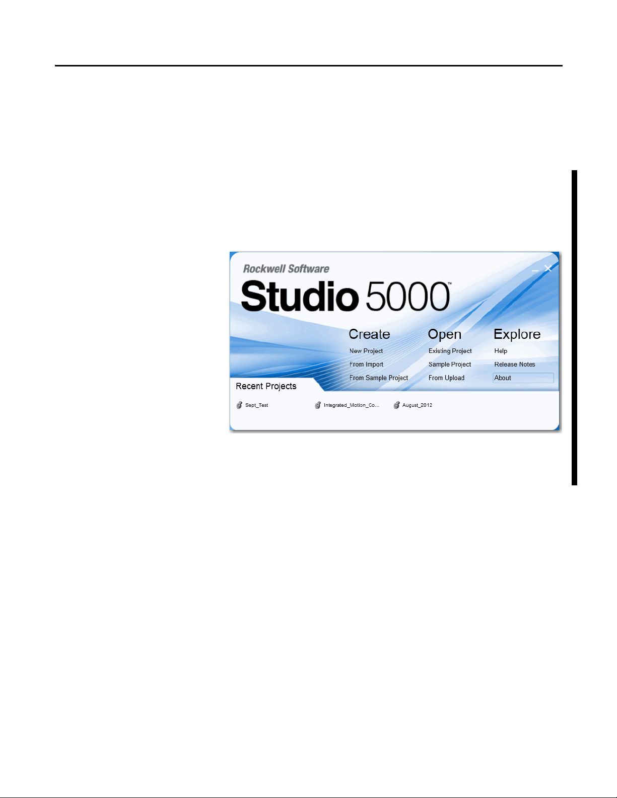
Studio 5000 Environment
The Studio 5000 Engineering and Design Environment combines engineering
and design elements into a common environment. The first element in the
Studio 5000 environment is the Logix Designer application. The Logix Designer
application is the rebranding of RSLogix 5000 software and will continue to be
the product to program Logix5000™ controllers for discrete, process, batch,
motion, safety, and drive-based solutions.
The Studio 5000 environment is the foundation for the future of Rockwell
Automation® engineering design tools and capabilities. It is the one place for
design engineers to develop all the elements of their control system.
Rockwell Automation Publication 1756-UM005B-EN-P - January 2013 9
Page 10
Preface
Additional Resources
These documents contain additional information concerning related products
from Rockwell Automation.
Resource Description
1756 ControlLogix I/O Modules Specifications
Technical Data, publication 1756-TD002
ControlLogix Analog I/O Modules User Manual,
publication 1756-UM009
ControlLogix System User Manual, publication 1756-UM001 Describes how to install, configure, program, and
ControlLogix Chassis and Power Supplies Installation
Instructions, publication 1756-IN005
Industrial Automation Wiring and Grounding Guidelines,
publication 1770-4.1
Product Certifications website, http://www.ab.com Provides declarations of conformity, certificates, and
Provides specifications for ControlLogix I/O modules.
Describes how to install, configure, and troubleshoot
ControlLogix analog I/O modules.
operate a ControlLogix system.
Describes how to install and troubleshoot standard and
ControlLogix-XT™ versions of the 1756 chassis and
power supplies, including redundant power supplies.
Provides general guidelines for installing a Rockwell
Automation industrial system.
other certification details.
You can view or download publications at
http://www.rockwellautomation.com/literature/
. To order paper copies of
technical documentation, contact your local Allen-Bradley distributor or
Rockwell Automation sales representative.
10 Rockwell Automation Publication 1756-UM005B-EN-P - January 2013
Page 11

Chapter 1
What is the ControlLogix
High-speed Analog I/O Module?
Top ic Pag e
Available Features 11
High-speed Analog I/O Modules in the ControlLogix System 12
The ControlLogix high-speed analog I/O module is an interface module that
converts analog signals to digital values for inputs and converts digital values to
analog signals for outputs. Using the producer/consumer network model, the
module produces information when needed while providing additional system
functions.
Available Features
The following are some of the features available on the module:
• Input Synchronization—This feature lets you synchronize the sampling of
inputs across multiple fast analog modules in the same chassis, allowing
those inputs to sample at the same rate within microseconds of each other.
For more information, see Synchronize Module Inputs
• Combination module offering 4 differential inputs and 2 outputs
• Sub-millisecond input sampling
• One millisecond output updates
• On-board alarms and scaling
• Removal and insertion under power (RIUP)
• Producer/consumer communication
• Rolling timestamp of data in milliseconds
• Coordinated System Time (CST) timestamp of data in microseconds
• IEEE 32 bit floating point
• Class I/Division 2, UL, CSA, CE, and C-Tick Agency Certification
To see a complete listing, including detailed explanations of all module features,
see Chapter 3
.
on page 45.
Rockwell Automation Publication 1756-UM005B-EN-P - January 2013 11
Page 12
Chapter 1 What is the ControlLogix High-speed Analog I/O Module?
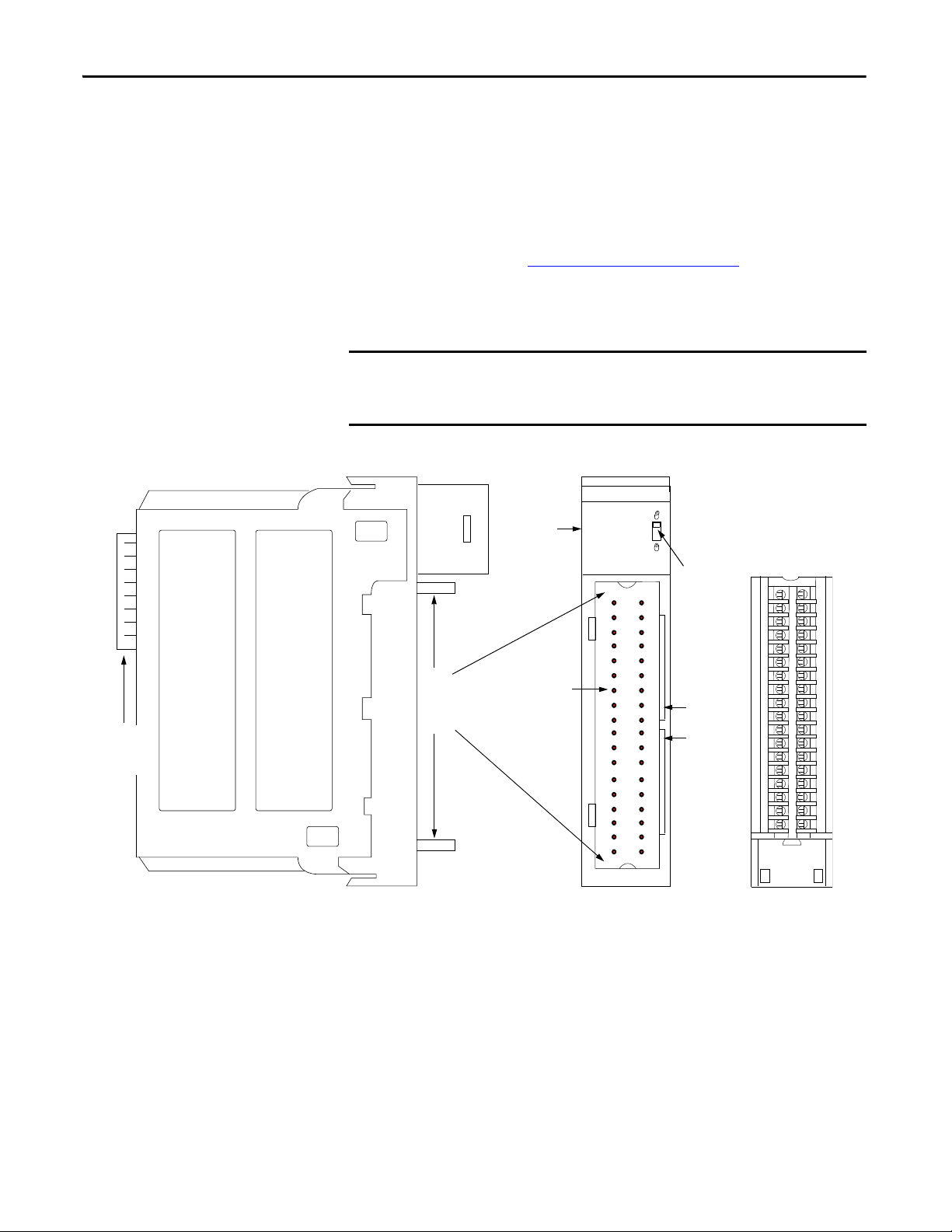
IMPORTANT
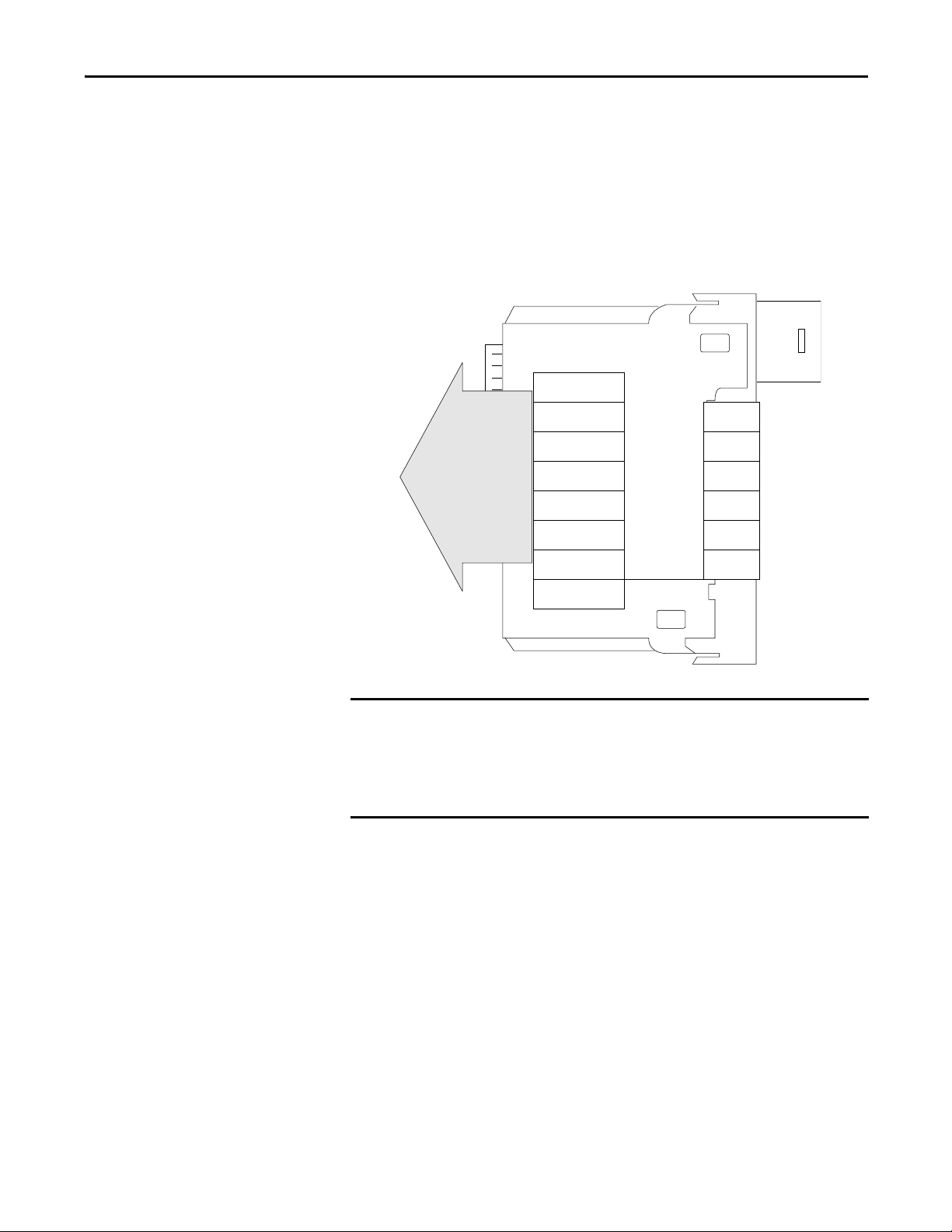
Control Logix
Backplane
Connector
Removable
Ter mi nal Bl ock
Indicators
Locking Tab
Slots for
Keying the
RTB
Connector Pins
Top an d
Bottom
Guides
41623
High-speed Analog I/O Modules in the ControlLogix System
A ControlLogix high-speed analog I/O module mounts in a ControlLogix
chassis and uses a Removable Terminal Block (RTB) or Interface Module (IFM)
to connect all field-side wiring.
Before you install and use your module, do the following :
• Install and ground a 1756 chassis and power supply. Refer to the
publications listed in Additional Resources
on page 10.
• Order and receive an RTB or IFM and its components for your
application.
RTBs and IFMs are not included with your module purchase. You must order
them separately. For more information, contact your local distributor or
Rockwell Automation representative.
Figure 1 - Physical Features of the High-speed Analog I/O Module
12 Rockwell Automation Publication 1756-UM005B-EN-P - January 2013
Page 13

What is the ControlLogix High-speed Analog I/O Module? Chapter 1
Ta b l e 1 lists the physical features on the ControlLogix high-speed analog I/O
module.
Table 1 - ControlLogix High-speed Analog I/O Module Physical Features
Feature Description
ControlLogix backplane connector Provides an interface to the ControlLogix system by connecting the module to
Connector pins Input/output, power, and grounding connections are made to the module
Locking tab Anchors the RTB on the module to maintain wiring connections.
Slots for keying Slots mechanically key the RTB to prevent you from making the wrong wire
Status indicators Display the status of communication, module health, and calibration
Top and bottom guides Provide assistance in seating the RTB onto the module.
the backplane.
through these pins with the use of an RTB.
connections to your module.
information. Use these indicators to help in troubleshooting.
Rockwell Automation Publication 1756-UM005B-EN-P - January 2013 13
Page 14

Chapter 1 What is the ControlLogix High-speed Analog I/O Module?
Notes:
14 Rockwell Automation Publication 1756-UM005B-EN-P - January 2013
Page 15

Chapter 2
IMPORTANT
High-speed Analog I/O Operation
in the ControlLogix System
Top ic Pag e
Ownership and Connections 16
Configure the Module 16
Direct Connections 17
Inputs and Outputs on the Same Module 18
Differences between Inputs and Outputs 20
Listen-only Mode 22
A ControlLogix high-speed analog I/O module’s performance behavior varies
depending upon whether it operates in the local chassis or in a remote chassis.
Module performance is limited in a remote chassis. The network cannot
effectively accommodate the fastest module update rates because the size of
the data broadcast requires a large portion of the network’s bandwidth. For
maximum module performance, we recommend you use it in a local chassis.
This chapter describes how the ControlLogix high-speed analog I/O module
operates in a local chassis. For more information on how the module operates
in a remote chassis, see Appendix
E.
Rockwell Automation Publication 1756-UM005B-EN-P - January 2013 15
Page 16

Chapter 2 High-speed Analog I/O Operation in the ControlLogix System
Ownership and Connections
Configure the Module
Every high-speed analog I/O module in the ControlLogix system must be owned
by a ControlLogix controller. This owner-controller stores configuration data for
the module and can be local or remote in reference to the module’s position. The
owner-controller sends the high-speed analog I/O module configuration data to
define the module’s behavior and begin operation.
The ControlLogix high-speed analog I/O module is limited to a single owner
and must continuously maintain communication with the owner to operate
normally.
ControlLogix input modules allow multiple owner-controllers that each store the
module’s configuration data. The high-speed analog I/O module, however, also
has outputs and cannot support multiple owner-controllers. Other controllers
can make listen-only connections to the module, though. For more information
on listen-only connections, see page 22
The I/O configuration portion of the Studio 5000 Logix Designer application
generates the configuration data for each high-speed analog I/O module in the
control system.
With the configuration dialog boxes in the Logix Designer application, you can
configure the inputs and outputs of a high-speed analog module at the same time.
Configuration data is transferred to the owner-controller during the program
download and subsequently transferred to the appropriate modules.
.
Follow these guidelines when configuring high-speed analog I/O modules.
1. Configure all modules for the controller by using the software.
2. Download configuration information to the controller.
3. Go online with your Logix Designer project to begin operation.
For more information on how to use the software to configure the module, see
Chapter 5
.
16 Rockwell Automation Publication 1756-UM005B-EN-P - January 2013
Page 17

High-speed Analog I/O Operation in the ControlLogix System Chapter 2
Direct Connections
A direct connection is a real-time data transfer link between the controller and
the module that occupies the slot that the configuration data references. When
module configuration data is downloaded to an owner-controller, the controller
attempts to establish a direct connection to each of the modules referenced by the
data.
If a controller has configuration data referencing a slot in the control system, the
controller periodically checks for the presence of a device there. When a device’s
presence is detected, the controller automatically sends the configuration data
and one of the following events occurs:
• If the data is appropriate to the module found in the slot, a connection is
made and operation begins.
• If the configuration data is not appropriate, the data is rejected, and an
error message appears in the software. In this case, the configuration data
can be inappropriate for any of a number of reasons. For example, a
module’s configuration data may be appropriate except for a mismatch in
electronic keying that prevents normal operation.
The controller continuously maintains and monitors its connection with a
module. Any break in the connection, such as removal of the module from the
chassis while under power, causes the controller to set fault status bits in the data
area associated with the module. Relay ladder logic may be used to monitor this
data area to detect the module’s failures.
Rockwell Automation Publication 1756-UM005B-EN-P - January 2013 17
Page 18

Chapter 2 High-speed Analog I/O Operation in the ControlLogix System
IMPORTANT
1
2
On-Board Memory
Status Data
Channel Data
Channel Data
Channel Data
Channel Data
Input 0
Input 1
Input 2
Input 3
Timestamp
Output Data Echo
Output Data Echo
Output 0
Output 1
Inputs and Outputs on the Same Module
The ControlLogix high-speed analog I/O module has 4 inputs and 2 outputs.
The following configurable parameters affect module behavior:
• Real Time Sample (RTS)
• Requested Packet Interval (RPI)
—Defines the input update rate.
—Defines the output update rate and
additional transfers of input data.
Real Time Sample (RTS)
The RTS is a configurable parameter (0.3…25 ms) that defines the input update
rate. This parameter causes the module to do the following.
1. Scan all input channels and store the data in on-board memory.
2. Multicast the updated channel data, as well as other status data, to the
backplane of the local chassis.
18 Rockwell Automation Publication 1756-UM005B-EN-P - January 2013
The RTS value is set during the initial configuration. This value can be adjusted
anytime. To use sub-millisecond values, type values with a decimal point. For
example, to use 800 ms, type 0.8.
For more information on how to set the RTS, see Chapter 5
.
Page 19
High-speed Analog I/O Operation in the ControlLogix System Chapter 2
IMPORTANT
On-Board Memory
Status Data
Channel Data
Channel Data
Channel Data
Channel Data
Timestamp
Output Data Echo
Output Data Echo
Input 0
Input 1
Input 2
Input 3
Output 0
Output 1
Requested Packet Interval (RPI)
The RPI is a configurable parameter that also instructs the module to multicast
its channel and status data to the local chassis backplane. However, the RPI
instructs the module to multicast the current contents of its on-board memory,
including input and output data echo, when the RPI expires. When the RPI
expires, the module does not update its channels prior to the multicast. The RPI
also instructs the owner-controller to update the module outputs.
The owner-controller sends output data to the high-speed analog I/O module
outputs asynchronously to when channel data and output data echo data are
returned over the ControlLogix backplane.
The RPI value is set during the initial module configuration. Adjusting the RPI
causes the connection to close and reopen.
Rockwell Automation Publication 1756-UM005B-EN-P - January 2013 19
Page 20
Chapter 2 High-speed Analog I/O Operation in the ControlLogix System
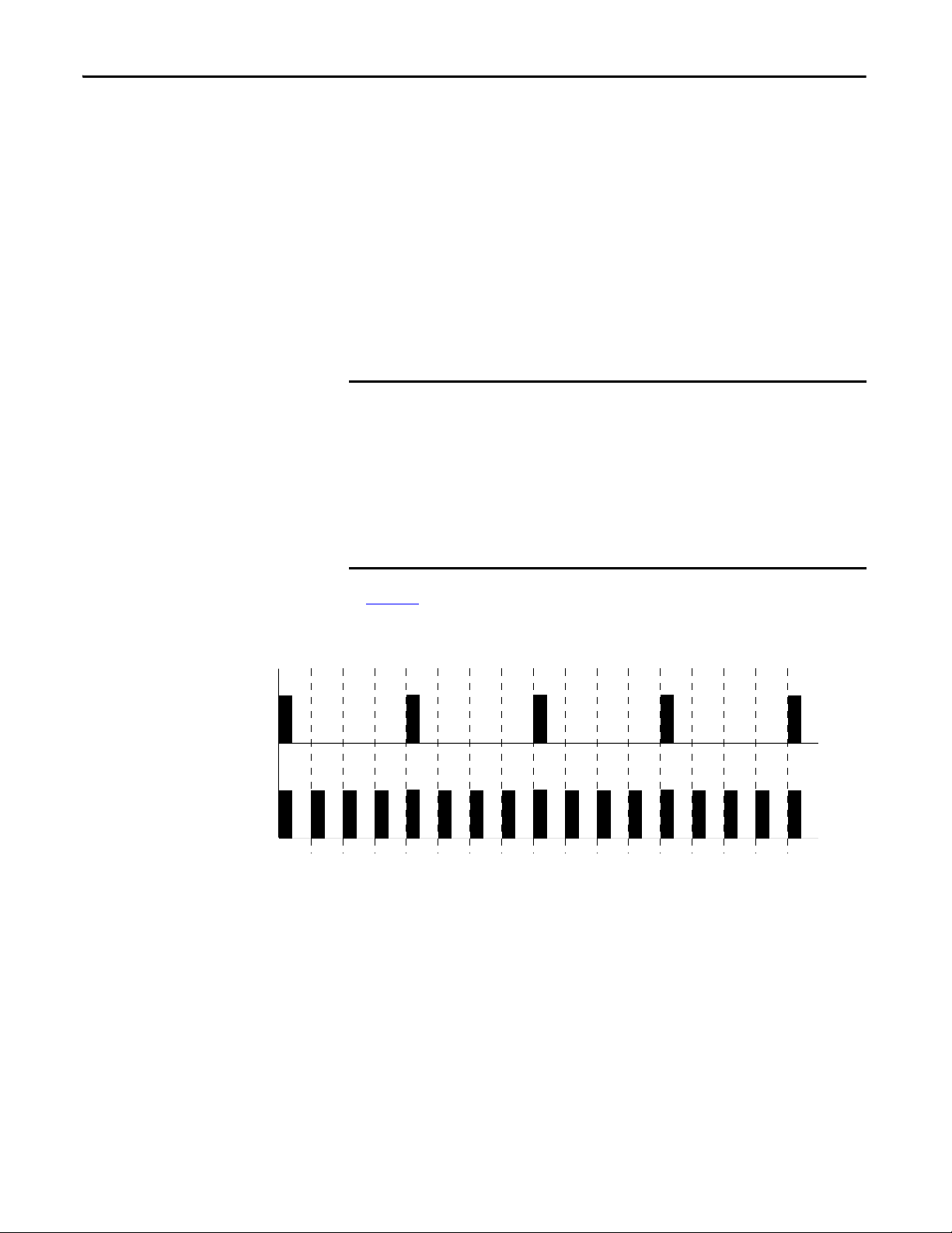
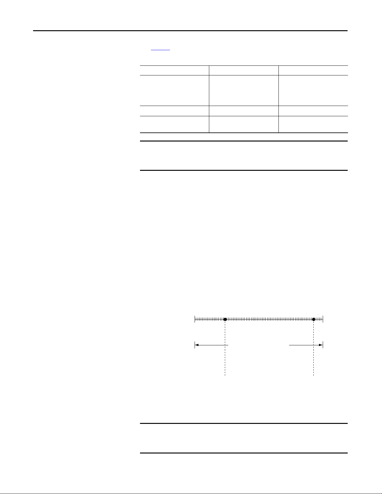
IMPORTANT
RTS
20 ms—Updated Input Data
RPI
5 ms—Updated and Old Data,
Depending on Time
5 10152025303540455055 60657075 80
Time (ms)
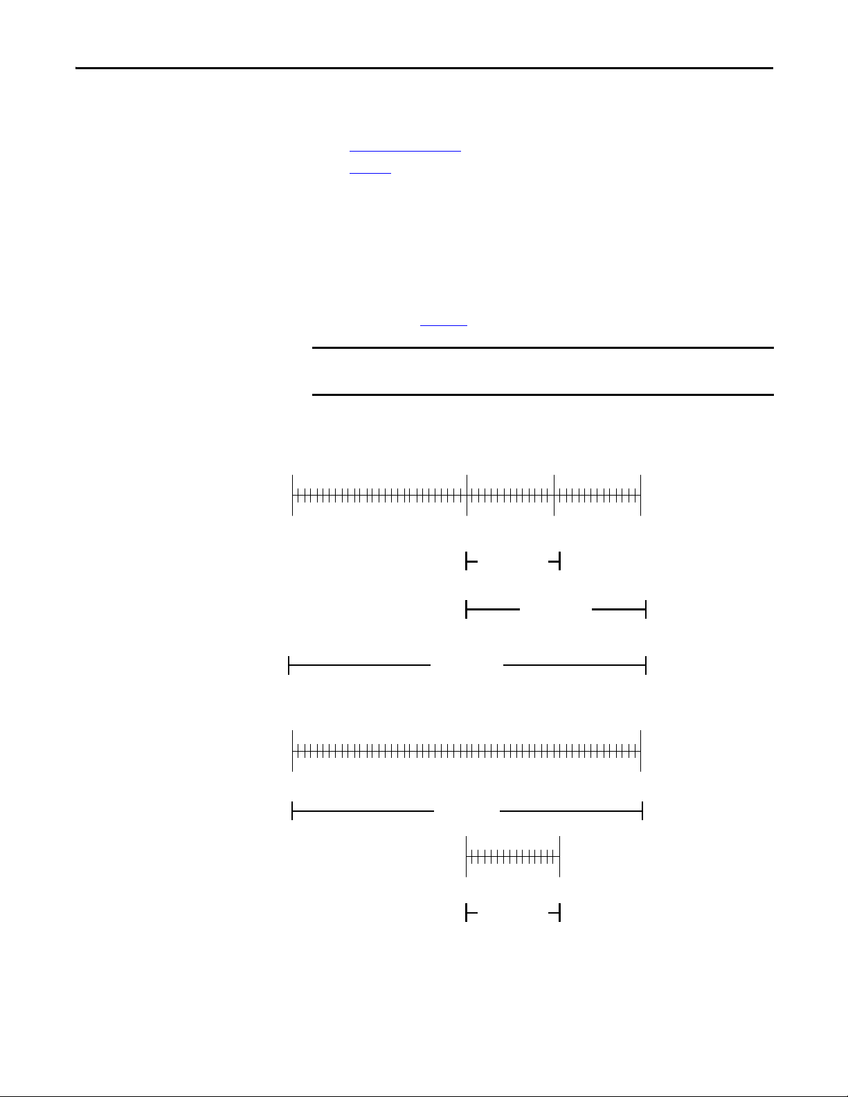
Updated input channel data is received at 0 ms, 20 ms, 40 ms, 60 ms, and 80 ms. The data
received at other RPI times repeats the most previous RTS. For example, data received at
30 ms repeats that received at 20 ms.
Differences between Inputs and Outputs
The ControlLogix high-speed analog I/O module uses both inputs and outputs.
However, there are significant differences between how each channel type
operates.
Module Input Operation
In traditional I/O systems, controllers poll module inputs to obtain their status.
The owner-controller does not poll the ControlLogix high-speed analog inputs
once a connection is established. Rather, the module multi-casts its input data
periodically. Multicast frequency depends on module configuration, such as RTS
and RPI rates.
The module only sends data at the RPI in these scenarios:
• RPI < RTS. In this case, the module multicasts at both the RTS rate and the
RPI rate. Their respective values dictate how often the owner-controller
receives data and how many multicasts from the module contain updated
channel data.
• If the RPI > RTS, each multicast from the module has updated channel
data. In effect, the module is only multicasting at the RTS rate.
• The module is operating in a mode where inputs are not being sampled, for
example calibration.
In Figure 2
, the RTS value is 20 ms and the RPI value is 5 ms. Only every fourth
multicast contains updated channel data.
Figure 2 - Input Data Update Rate
20 Rockwell Automation Publication 1756-UM005B-EN-P - January 2013
Page 21
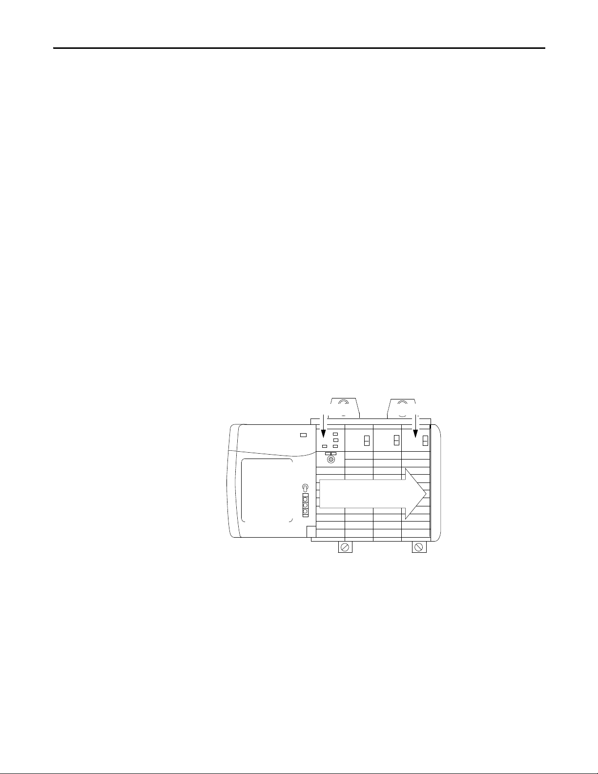
High-speed Analog I/O Operation in the ControlLogix System Chapter 2
Data Sent from Owner at the RPI
Owner-controller High-speed Analog I/O Module
Module Output Operation
When specifying an RPI value for the high-speed analog I/O module, you define
when the controller broadcasts output data to the module. If the module resides
in the same chassis as the owner-controller, the module receives the data almost
immediately.
High-speed analog module outputs receive data from the owner-controller and
echo output data only at the period specified in the RPI. Data is not sent to the
module at the end of the controller’s program scan.
When a high-speed analog I/O module receives new data from an
owner-controller, the module multicasts or echoes the output data value that
corresponds to the analog signal applied to the output terminals
the control system at the next RPI or RTS, whichever occurs first. This feature,
called Output Data Echo.
Depending on the value of the RPI, with respect to the length of the controller
program scan, the module can receive and echo data multiple times during one
program scan.
(1)
to the rest of
Because it is not dependent on reaching the end of the program to send data, the
controller effectively allows the module’s output channels to change values
multiple times during a single program scan when the RPI is less than the
program scan length.
(1) Although the output value at the RTB screw terminal typically matches the output data e cho value, it is not guaranteed to match.
The output data echo that is multicast to the rest of the control system represents the value the outputs were commanded to be.
Rockwell Automation Publication 1756-UM005B-EN-P - January 2013 21
Page 22

Chapter 2 High-speed Analog I/O Operation in the ControlLogix System
IMPORTANT
Listen-only Mode
Any controller in the system can listen to the data from a high-speed analog I/O
module (input data or echoed output data) even if the controller does not own
the module. The module does not have to hold the module’s configuration data
to listen to the module.
During the I/O configuration process, you can specify a Listen-only mode in the
Communication Format field. For more information on Communication
Format, see page 75
Choosing a Listen-only mode option allows the controller and module to
establish communication without the controller sending any configuration data.
In this instance, another controller owns the module being listened to and stores
the module’s configuration data.
.
Controllers using the Listen-only mode continue to receive data multicast from
the I/O module as long as a connection between an owner and I/O module is
maintained.
If the connection between the owner and the module is broken, the module
stops multicasting data and connections to all listening controllers are also
broken.
22 Rockwell Automation Publication 1756-UM005B-EN-P - January 2013
Page 23

Chapter 3
Module Features
Top ic Pag e
Input Compatibility 23
Output Compatibility 23
General Module Features 24
Electronic Keying 25
Understand Module Resolution, Scaling and Data Format 35
Features Specific to ModuleInputs 37
Features Specific to Module Outputs 46
Fault and Status Reporting 49
Input Compatibility
Output Compatibility
ControlLogix high-speed analog I/O module inputs convert the following
analog signals into digital values:
• Vo l t s
• Milliamps
The digital value that represents the magnitude of the analog signal is then
transmitted on the backplane to an owner-controller or other control entities.
ControlLogix high-speed analog I/O module outputs convert a digital value
delivered to the module via the backplane into an analog signal:
• -10.5…10.5V
or
• 0…21 mA
The digital value represents the magnitude of the desired analog signal. The
module converts the digital value into an analog signal and provides this signal on
the module's screw terminals.
Rockwell Automation Publication 1756-UM005B-EN-P - January 2013 23
Page 24

Chapter 3 Module Features
General Module Features
This section describes features available on ControlLogix high-speed analog I/O
modules that are common with other ControlLogix I/O modules.
Removal and Insertion Under Power (RIUP)
ControlLogix high-speed analog I/O modules may be inserted and removed
from the chassis while power is applied. This feature allows greater availability of
the overall control system because, while the module is being removed or
inserted, there is no additional disruption to the rest of the controlled process.
Module Fault Reporting
ControlLogix high-speed analog I/O modules provide both hardware and
software indication when a module fault has occurred. Each module has a fault
status indicator. The Logix Designer application graphically displays the fault
and includes a fault message describing the nature of the fault. This feature lets
you to determine how your module has been affected and what action to take to
resume normal operation.
For more information about fault and status reporting, see page 49
.
Fully Software Configurable
The Logix Designer application uses an interface to configure the module. All
module features are enabled or disabled through the I/O configuration portion
of the application.
The user can also use the software to interrogate any module in the system to
retrieve the following:
• Serial number
• Revision information
• Catalog number
• Vendor identification
• Error/fault information
• Diagnostic counters
24 Rockwell Automation Publication 1756-UM005B-EN-P - January 2013
Page 25
Module Features Chapter 3
IMPORTANT
Electronic Keying
The electronic keying feature automatically compares the expected module, as
shown in the Logix Designer I/O Configuration tree, to the physical module
before I/O communication begins. You can use electronic keying to help prevent
communication to a module that does not match the type and revision expected.
For each module in the I/O Configuration tree, the user-selected keying option
determines if, and how, an electronic keying check is performed. Typically, three
keying options are available:
• Exact Match
• Compatible Keying
• Disabled Keying
You must carefully consider the benefits and implications of each keying option
when selecting between them. For some specific module types, fewer options are
available.
Electronic keying is based on a set of attributes unique to each product revision.
When a Logix5000 controller begins communicating with a module, this set of
keying attributes is considered.
Table 2 - Keying Attributes
Attribute Description
Vendor The manufacturer of the module, for example, Rockwell Automation/Allen-Bradley.
Product Type The general type of the module, for example, communication adapter, AC drive, or digital
I/O.
Product Code The specific type of module, generally represented by its catalog number, for example,
1756-IB16I.
Major Revision A number that represents the functional capabilities and data exchange formats of the
module. Typically, although not always, a later, that is higher, Major Revision supports at
least all of the data formats supported by an earlier, that is lower, Major Revision of the
same catalog number and, possibly, additional ones.
Minor Revision A number that indicates the module’s specific firmware revision. Minor Revisions
typically do not impact data compatibility but may indicate performance or behavior
improvement.
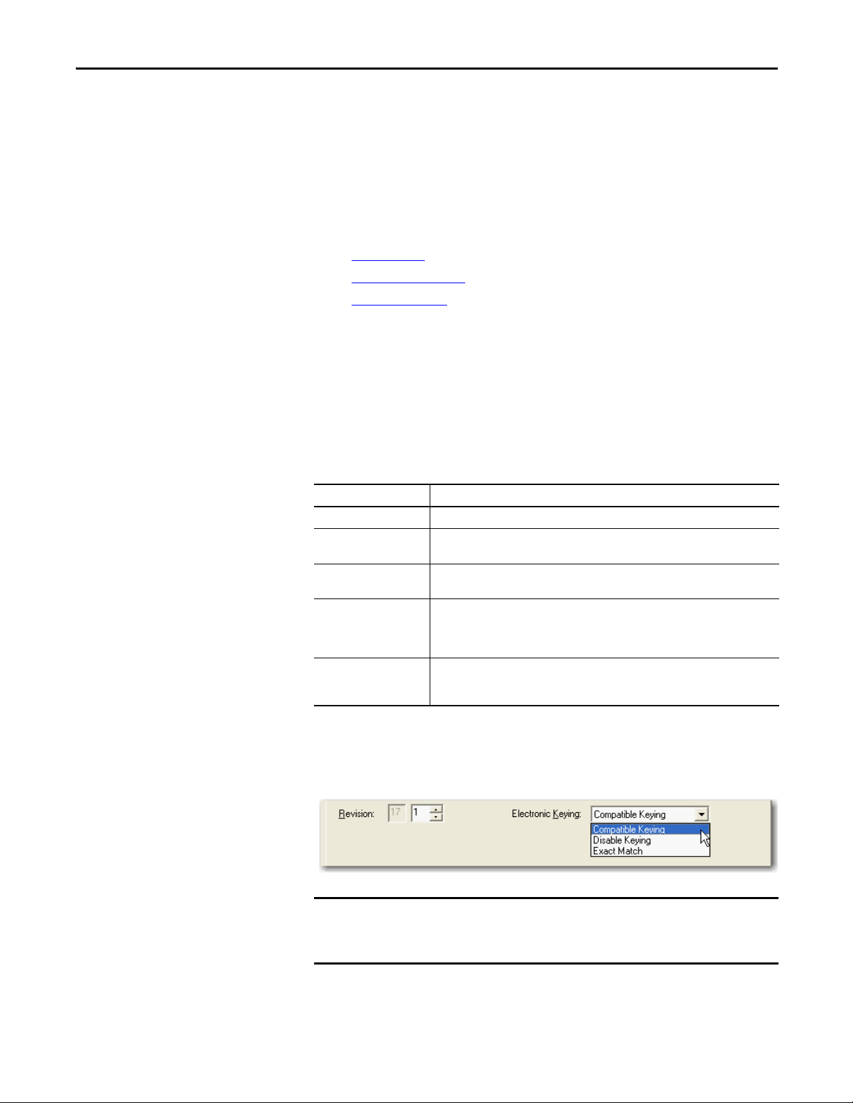
You can find revision information on the General tab of a module’s Properties
dialog box.
Figure 3 - General Tab
Changing electronic keying selections online may cause the I/O
communication connection to the module to be disrupted and may result in a
loss of data.
Rockwell Automation Publication 1756-UM005B-EN-P - January 2013 25
Page 26
Chapter 3 Module Features
EXAMPLE
IMPORTANT
Module Configuration
Vendor = Allen-Bradley
Product Type = Digital Input Module
Catalog Number = 1756-IB16D
Major Revision = 3
Minor Revision = 1
Physical Module
Vendor = Allen-Bradley
Product Type = Digital Input Module
Catalog Number = 1756-IB16D
Major Revision = 3
Minor Revision = 2
Communication is prevented.
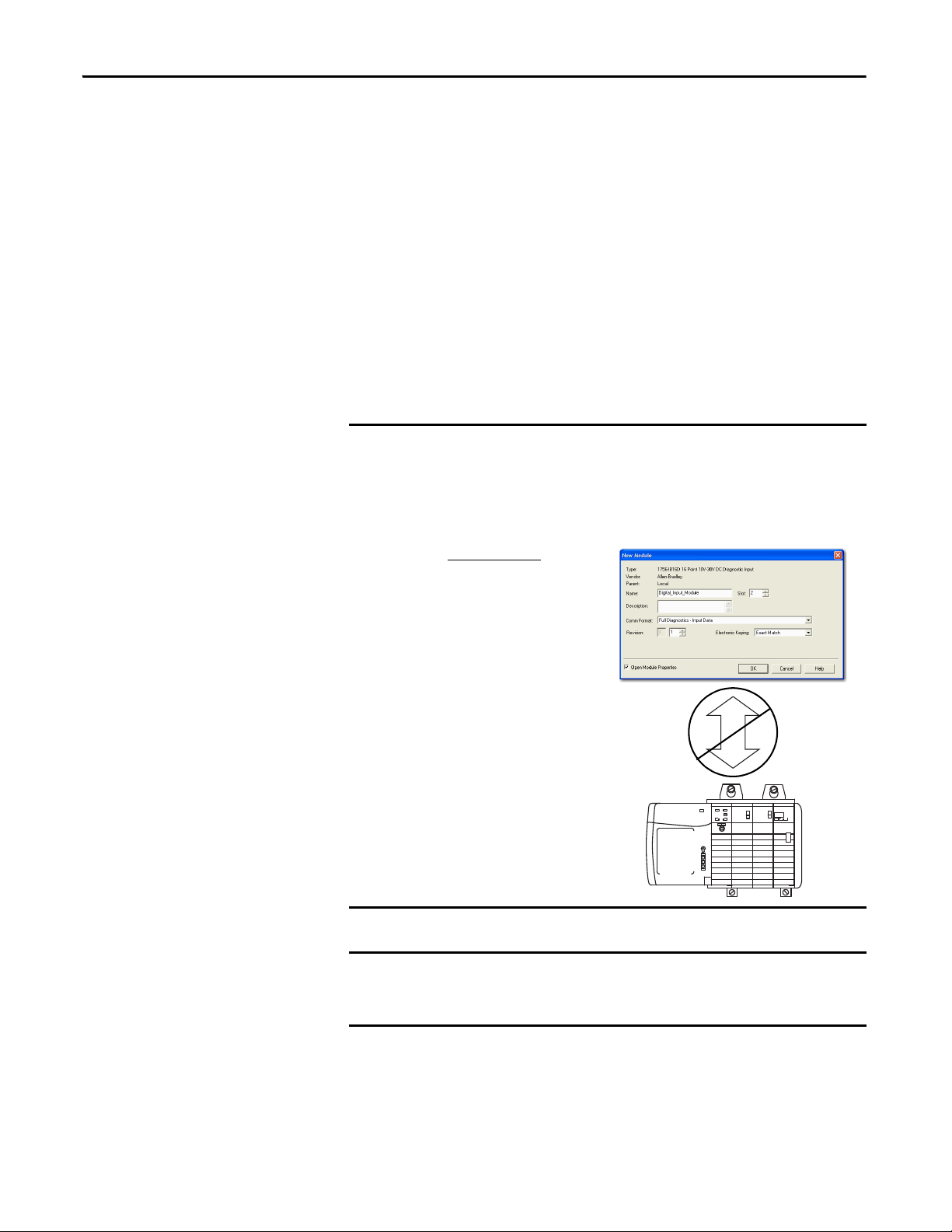
Exact Match
Exact Match keying requires all keying attributes, that is, Vendor, Product Type,
Product Code (catalog number), Major Revision, and Minor Revision, of the
physical module and the module created in the software to match precisely to
establish communication. If any attribute does not match precisely, I/O
communication is not permitted with the module or with modules connected
through it, as in the case of a communication module.
Use Exact Match keying when you need the system to verify that the module
revisions in use are exactly as specified in the project, such as for use in highlyregulated industries. Exact Match keying is also necessary to enable Automatic
Firmware Update for the module via the Firmware Supervisor feature from a
Logix5000 controller.
In this scenario, Exact Match keying prevents I/O communication.
The module configuration is for a 1756-IB16D module with module revision
3.1. The physical module is a 1756-IB16D module with module revision 3.2. In
this case, communication is prevented because the Minor Revision of the
module does not match precisely.
26 Rockwell Automation Publication 1756-UM005B-EN-P - January 2013
Changing electronic keying selections online may cause the I/O
Communication connection to the module to be disrupted and may result in a
loss of data.
Page 27

Module Features Chapter 3
Compatible Keying
Compatible Keying indicates that the module determines whether to accept or
reject communication. Different module families, communication adapters, and
module types implement the compatibility check differently based on the family
capabilities and on prior knowledge of compatible products. Release notes for
individual modules indicate the specific compatibility details.
Compatible Keying is the default setting. Compatible Keying allows the physical
module to accept the key of the module configured in the software, provided that
the configured module is one the physical module is capable of emulating. The
exact level of emulation required is product and revision specific.
With Compatible Keying, you can replace a module of a certain Major Revision
with one of the same catalog number and the same or later, that is higher, Major
Revision. If a Major Revision is the same, then make sure that the Minor Revision
is the same or higher than it is configured in the project. In some cases, the
selection makes it possible to use a replacement that is a different catalog number
than the original. For example, you can replace a 1756-CNBR module with a
1756-CN2R module.
When a module is created, the module developers consider the module’s
development history to implement capabilities that emulate those of the previous
module. However, the developers cannot know future developments. Because of
this, when a system is config ured, we recommend that you configure your module
using the earliest, that is, lowest, revision of the physical module that you believe
will be used in the system. By doing this, you can avoid the case of a physical
Rockwell Automation Publication 1756-UM005B-EN-P - January 2013 27
Page 28
Chapter 3 Module Features
EXAMPLE
Module Configuration
Vendor = Allen-Bradley
Product Type = Digital Input Module
Catalog Number = 1756-IB16D
Major Revision = 3
Minor Revision = 3
Physical Module
Vendor = Allen-Bradley
Product Type = Digital Input Module
Catalog Number = 1756-IB16D
Major Revision = 3
Minor Revision = 2
Communication is prevented.
module rejecting the keying request because it is an earlier revision than the one
configured in the software.
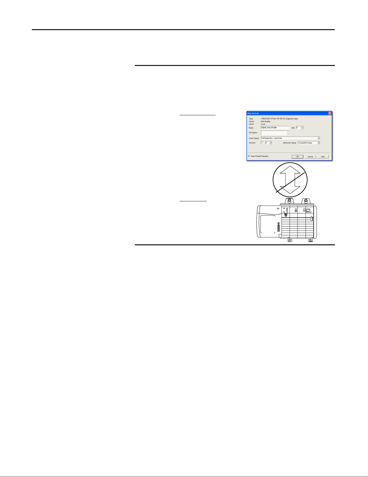
In this scenario, Compatible Keying prevents I/O communication.
The module configuration is for a 1756-IB16D module with module revision
3.3. The physical module is a 1756-IB16D module with module revision 3.2.
In this case, communication is prevented because the minor revision of the
module is lower than expected and may not be compatible with 3.3.
28 Rockwell Automation Publication 1756-UM005B-EN-P - January 2013
Page 29

Module Features Chapter 3
EXAMPLE
IMPORTANT
Module Configuration
Vendor = Allen-Bradley
Product Type = Digital Input Module
Catalog Number = 1756-IB16D
Major Revision = 2
Minor Revision = 1
Physical Module
Vendor = Allen-Bradley
Product Type = Digital Input Module
Catalog Number = 1756-IB16D
Major Revision = 3
Minor Revision = 2
Communication is allowed.
In this scenario, Compatible Keying allows I/O communication.
The module configuration is for a 1756-IB16D module with module revision
2.1. The physical module is a 1756-IB16D module with module revision 3.2. In
this case, communication is allowed because the major revision of the physical
module is higher than expected and the module determines that it is
compatible with the prior major revision.
Changing electronic keying selections online may cause the I/O
communication connection to the module to be disrupted and may result in a
loss of data.
Rockwell Automation Publication 1756-UM005B-EN-P - January 2013 29
Page 30
Chapter 3 Module Features
EXAMPLE
Module Configuration
Vendor = Allen-Bradley
Product Type = Digital Input Module
Catalog Number = 1756-IA16
Major Revision = 3
Minor Revision = 1
Physical Module
Vendor = Allen-Bradley
Product Type = Analog Input Module
Catalog Number = 1756-IF16
Major Revision = 3
Minor Revision = 2
Communication is prevented.
Disabled Keying
Disabled Keying indicates the keying attributes are not considered when
attempting to communicate with a module. Other attributes, such as data size
and format, are considered and must be acceptable before I/O communication is
established. With Disabled Keying, I/O communication may occur with a
module other than the type specified in the I/O Configuration tree with
unpredictable results. We generally do not recommend using Disabled Keying.
ATT EN TI ON : Be extremely cautious when using Disabled Keying; if used
incorrectly, this option can lead to personal injury or death, property damage,
or economic loss.
If you use Disabled Keying, you must take full responsibility for understanding
whether the module being used can fulfill the functional requirements of the
application.
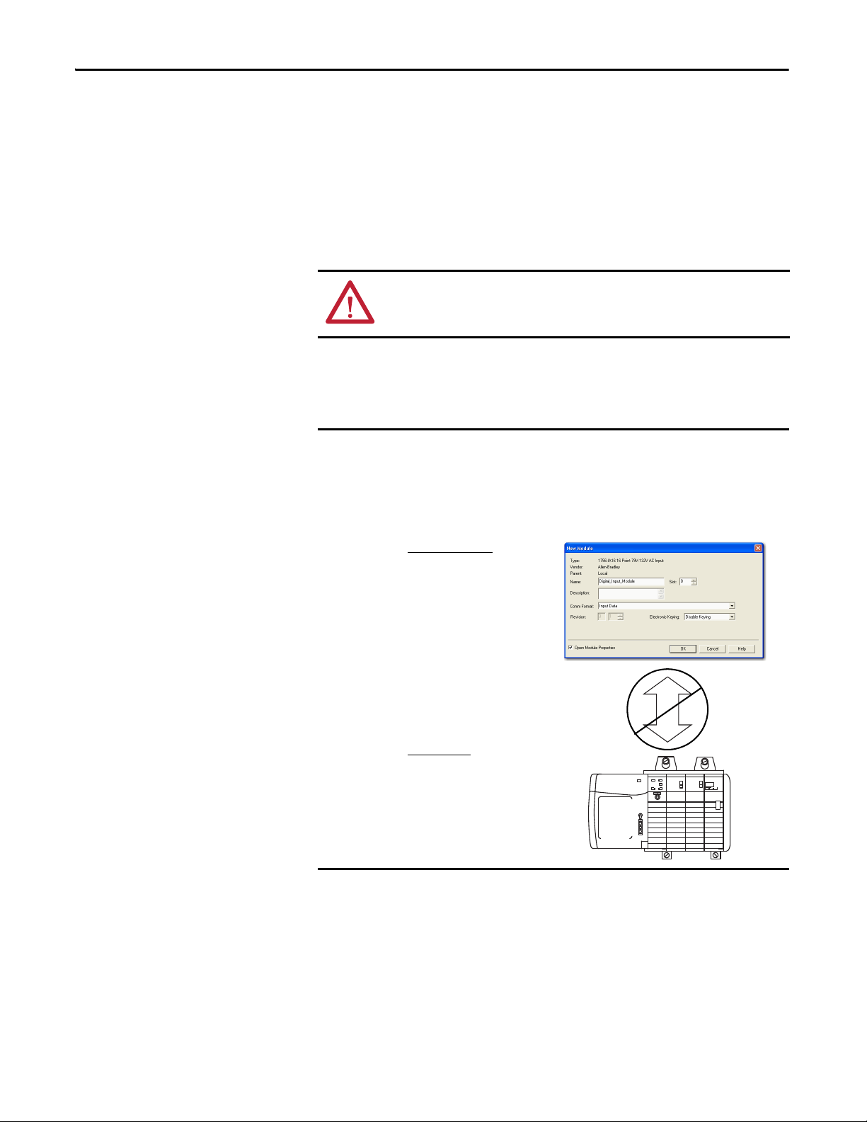
In this scenario, Disable Keying prevents I/O communication.
The module configuration is for a 1756-IA16 digital input module. The physical
module is a 1756-IF16 analog input module. In this case, communication is
prevented because the analog module rejects the data formats that the digital
module configuration requests.
30 Rockwell Automation Publication 1756-UM005B-EN-P - January 2013
Page 31

Module Features Chapter 3
EXAMPLE
IMPORTANT
Module Configuration
Vendor = Allen-Bradley
Product Type = Digital Input Module
Catalog Number = 1756-IA16
Major Revision = 2
Minor Revision = 1
Physical Module
Vendor = Allen-Bradley
Product Type = Digital Input Module
Catalog Number = 1756-IB16
Major Revision = 3
Minor Revision = 2
Communication is allowed.
In this scenario, Disable Keying allows I/O communication.
The module configuration is for a 1756-IA16 digital input module. The physical
module is a 1756-IB16 digital input module. In this case, communication is
allowed because the two digital modules share common data formats.
Changing electronic keying selections online may cause the I/O
communication connection to the module to be disrupted and may result in a
loss of data.
Rockwell Automation Publication 1756-UM005B-EN-P - January 2013 31
Page 32

Chapter 3 Module Features
Access to System Clock for Timestamping Functions
Certain modules, such as controllers, in the ControlLogix chassis maintain a
system clock. The clock is a free-running, 64-bit number that increments every
microsecond. It is used to places a timestamp on the sampling of input data
within the local chassis.
You can configure your high-speed analog I/O modules to access this clock and
timestamp input data when the module multicasts to the system. You decide how
to timestamp data when you choose a communication format. For more
information about choosing a communication format, see page 75
This feature allows for accurate calculations between events to help you identify
the sequence of events in either fault conditions or in the course of normal I/O
operations. This clock is also used to synchronize inputs across multiple modules
in the same chassis. For more information about synchronizing module inputs,
see page 45
.
.
Rolling Timestamp
Each high-speed analog I/O module maintains a rolling timestamp that is
unrelated to the Coordinated System Time (CST). The rolling timestamp is an
on-board, continuously running 15-bit timer that counts in milliseconds.
For module inputs, when the module scans its input channels, it also records the
value of the rolling timestamp at that time. The user program can then use the
last two rolling timestamp values and calculate the interval between receipt of
data or the time when new data has been received.
Because the high-speed analog I/O module offers sub-millisecond sample times
and the rolling timestamp counts in milliseconds, it is possible that a new sample
can be taken without altering the rolling timestamp. If accurate time deltas are
required in such sub-millisecond cases, the CST timestamp’s lower 32 bits offer
the necessary precision.
Producer/Consumer Model
The producer/consumer model is an intelligent data exchange between modules
and other system devices in which each module produces data without having
first been polled. The modules produce the data and any owner or listen-only
controller device can decide to consume it.
For example, module inputs produce data and any number of processors can
consume the data at the same time. This eliminates the need for one processor to
send the data to another processor. For a more detailed explanation of this
process, see Chapter 2
32 Rockwell Automation Publication 1756-UM005B-EN-P - January 2013
.
Page 33

Module Features Chapter 3
IMPORTANT
Status Information
Each ControlLogix high-speed analog I/O module has status indicators that
allow you to check module health and operational status.
The following status can be checked with the indicators:
•Calibration status—The display blinks to indicate when your module is
in the Calibration mode.
•Module status—The display indicates the module’s communication
status.
To see the status indicators on the ControlLogix high-speed analog I/O module,
see Chapter 7
.
Full Class I Division 2 Compliance
All ControlLogix high-speed analog I/O modules maintain CSA Class I
Division 2 system certification. This allows the ControlLogix system to be placed
in an environment other than only a 100% hazard free.
Do not pull modules under power or remove a powered RTB when a hazardous
environment is present.
CE/CSA/UL/C-Tick Agency Certification
The ControlLogix high-speed analog I/O module has obtained multiple agency
certifications, such as CE, CSA, UL, and C-Tick. If the module has received an
agency certification, it is marked as such.
Field Calibration
ControlLogix high-speed analog I/O modules allow you to calibrate each
channel individually or in groups, such as all inputs at once. The Logix Designer
application provides an interface to perform calibration.
To see how to calibrate your module, see Chapter 6
.
Rockwell Automation Publication 1756-UM005B-EN-P - January 2013 33
Page 34

Chapter 3 Module Features
IMPORTANT
Latching of Alarms
The latching feature allows the high-speed analog I/O module to latch an alarm
in the set position once it has been triggered, even if the condition causing the
alarm to occur disappears. Once an alarm is latched, you must unlatch it via the
Logix Designer application or a message instruction.
To see how to unlatch an alarm, see page 77
.
Alarm Disable
The Logix Designer application provides the option to disable all of the process
alarms available on the module, as described on pages 44
To see how to disable the process alarms, see page 77
, 45, and 48.
.
Data Format
Your high-speed analog I/O module multicasts floating point data. Floating
point data uses a 32-bit IEEE format. Integer mode is not available on the
ControlLogix high-speed analog I/O module.
Module Inhibiting
Module inhibiting provides the option to close the connection between a
high-speed analog I/O module and its owner-controller. This feature stops the
data transfer between the owner-controller and a configured module. The
connection is reopened when the module is uninhibited.
Whenever you inhibit a high-speed analog I/O module, all outputs change to
the state configured for the Program mode.
For example, if the module is configured so that the state of the outputs go to
zero during Program mode, whenever the module is inhibited, the outputs go
to zero.
34 Rockwell Automation Publication 1756-UM005B-EN-P - January 2013
Page 35
Module Features Chapter 3
IMPORTANT
4096 Counts
-10V 0V 5V 10V
8192 Counts
16,384 Counts
0 mA 21 mA
8192 Counts
Voltage Resolution
Current Resolution
0…5V (actual limit = 5.25V)
Inputs Only
0…10V (actual limit = 10.5V)
Inputs Only
-10…10V (actual limit = -10.5V …10.5V)
Inputs and Outputs
0…21 mA
Outputs use 8192 counts of
current resolution.
4096 Counts
0 mA 21 mA
0 to 21 mA
Inputs use 4096 counts of
current resolution.
Understand Module Resolution, Scaling and Data Format
The following three concepts are closely related and must be explained in
conjunction with each other:
• Module Resolution
• Scaling
Module Resolution
Resolution is the smallest amount of change that the module can detect.
High-speed analog I/O modules are capable of 14-bit resolution. The 14 bits
represent 16,384 counts. Depending on the operating range, the available counts
varies, as shown in Figure 4
A module’s resolution is fixed. It does not change regardless of how you decide
to scale your module.
Figure 4 - Available Counts
.
Rockwell Automation Publication 1756-UM005B-EN-P - January 2013 35
Page 36
Chapter 3 Module Features
IMPORTANT
IMPORTANT
Module Resolution
4096 Counts
0 mA 21 mA
4 mA 20 mA
0% in Engineering Units 100% in Engineering Units
Module Scaling
Module scaling represents the data returned from the module to the controller.
Use Ta b l e 3 to see the resolution for each module range.
Table 3 - Module Resolution Range
Input Range Effective Bits across Range Resolution
±10V
0V…10V
0V…5V
0 mA…21 mA
Output Range Effective Bits across Range Resolution
±10V
0 mA…21 mA
14 bits
13 bits
12 bits
12 bits
14 bits
13 bits
1.3 mV/count
1.3 mV/count
1.3 mV/count
5.25 μA/count
1.3mV/count
2.8μA/count
Because this module must allow for possible calibration inaccuracies,
resolution values represent the available analog-to-digital or digital-to-analog
counts over the specified range.
Scaling
The scaling feature provides the option to change a quantity from one notation to
another. When you scale a channel, you must choose two points along the
channel’s operating range and apply low and high values to those points.
For example, if you use an input in Current mode, the channel maintains a
0…21mA range capability. But your application may use a 4…20 mA transmitter.
You can scale the module to represent 4 mA as the low signal and 20 mA as the
high signal and scale that into engineering units of your choice.
In this case, scaling can cause the module to return data to the controller so that
4 mA returns a value of 0% in engineering units and 20 mA returns a value of
100% in engineering units.
Figure 5 - Module Resolution Compared to Module Scaling
In choosing two points for the low and high value of your application, you do
not limit the range of the module. The module’s range and its resolution
remain constant regardless of how you scale it for your application.
36 Rockwell Automation Publication 1756-UM005B-EN-P - January 2013
Page 37

Module Features Chapter 3
The module may operate with values beyond the 4 mA…20 mA range. If an input
signal beyond the low and high signals is present at the module, such as 3 mA,
that data is represented in terms of the engineering units set during scaling.
Ta b l e 4
shows example values that may appear based the example mentioned
previously.
Table 4 - Current Values Represented in Engineering Units
Current Engineering Units Value
3 mA -6.25%
4 mA 0%
12 mA 50%
20 mA 100%
21 mA 106.25%
Features Specific to Module Inputs
The following features are specific to high-speed analog I/O module inputs:
• Archiving
• Multiple Input Ranges
• Underrange/Overrange Detection
• Digital Filter
• Process Alarms
• Rate Alarm
• Synchronize Module Inputs
Rockwell Automation Publication 1756-UM005B-EN-P - January 2013 37
Page 38

Chapter 3 Module Features
IMPORTANT
EXAMPLE
IMPORTANT
Archiving
Archiving is available only with the following:
• Module firmware revision 3.005 or later
For more information about upgrading a series A module with series B
firmware, see Appendix F
• RSLogix 5000 software version 16.03.00 or later, or the Studio 5000
environment version 21.00.00 or later
Archiving is an input scanning function that lets the high-speed analog module
store as many as 20 input data samples for each channel in the module’s on-board
buffers before it sends the I/O data to the controller.
By storing the channel data until 20 samples are taken, the module lengthens the
time between I/O data transfers, resulting in a better use of controller task
resources by batching the samples into 1 large transfer rather than 20 small
transfers.
When a Real Time Sample (RTS) period is defined during configuration, it
defines the interval in which the module scans for new data from each of the
input channels, for example, RTS period = one input data sample per channel.
.
Without archiving, the module sends this channel data at the completion of
every channel scan, for example, every RTS period. Because archiving permits the
module to store 20 channel scans worth of data on-board before transferring it to
the controller, the system can effectively record channel data without excessively
burdening the backplane or controller.
If the module is set to scan its channels at the fastest rate possible, for
example, RTS = 300 μs, rather than sending data to the controller at that
frequency, the module sends data as defined by this formula:
Archive data transfer rate = 20 x RTS chosen by the user
In this case, with the RTS period for high-speed analog module = 300 μs, the
module fills its on-board buffers with data at the rate defined by that RTS, but
transfers the data to the controller only every 6 ms (20 samples x 300 μs).
The high-speed scanning that occurs when archiving applies only to the inputs
on the module and not the outputs. The outputs are updated at the RPI rate.
38 Rockwell Automation Publication 1756-UM005B-EN-P - January 2013
Page 39
Module Features Chapter 3
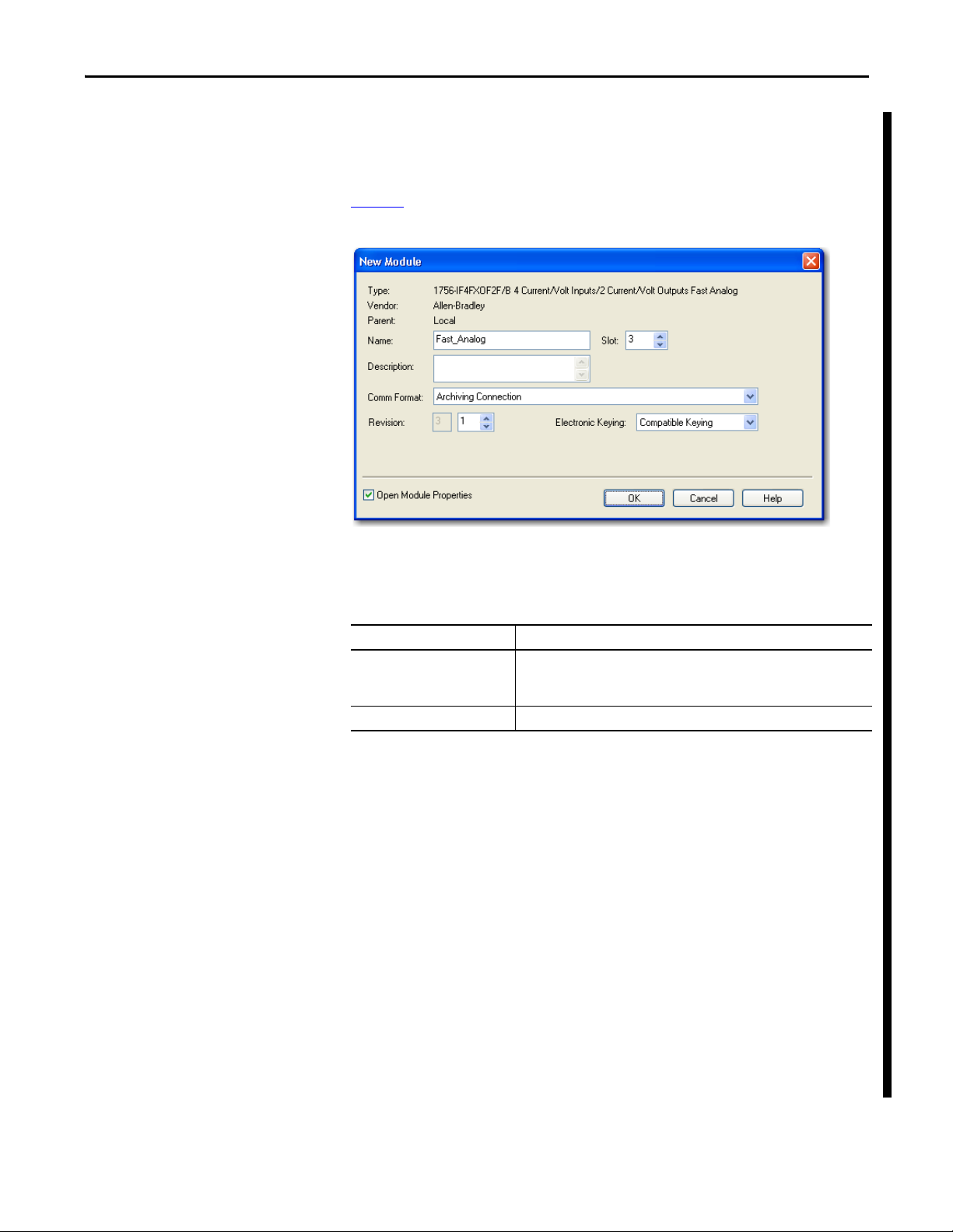
Enable Archiving via the Communication Format
To use archiving, you must select the 1756-IF4FXOF2F/B configuration profile,
and then choose the Archiving Connection communication format, as shown in
Figure 6
Figure 6 - Archiving Connection Communication Format
.
The Archiving Connection communication format creates two additional tags in
the input structure of the module, as described below.
Table 5 - Archiving Tags
Tag Description
I.LastUpdateIndex Returns the number of the last archive sample performed by the module before
I.Input An array that stores channel data for each of the 20 archive samples (0…19).
data was sent to the controller.
This tag equals 19 when the RPI is greater than (20 * RTS).
Determine RPI
When archiving is enabled, we recommend that you set the requested packet
interval (RPI) of the module at a rate equal to or greater than 20 times the Real
Time Sample (RTS) rate. You can determine the recommended RPI by using the
following equation.
RPI = (RTS x 20)
The fastest RTS rate available for use with the high-speed analog module is
300 µs. If the RTS is set at 300 µs, set the RPI to at least 6 ms or higher as shown
below.
6 ms = (300 µs x 20)
For more information about determining RPI and RTS rates with archiving
enabled, search the Rockwell Automation Knowledgebase for answer ID 40228.
Rockwell Automation Publication 1756-UM005B-EN-P - January 2013 39
Page 40

Chapter 3 Module Features
TIP
IMPORTANT
Use Archiving
Follow these steps to use archiving.
1. Choose a Real Time Sample (RTS) period appropriate for your
application.
The module supports sample periods as fast as 300 s. However, only
RSLogix 5000 software, version 18.02.00 or later, or the Studio 5000
environment, version 21.00.00 or later, lets you enter that value in the
profile during module configuration.
RSLogix 5000 software, version 17.01.02 or earlier, requires that you enter
a minimum 400 s RTS period via the profile. You must enter a value of
0.3 in the C.RealTimeSample tag to achieve a 300 s RTS.
The module’s outputs are updated only at the defined RPI rate.
Consider output behavior when choosing an RPI.
2. Calculate your RPI: Choose an RPI that is equal to 20 x RTS.
For example, if you choose a 400 s RTS, and then set your RPI to 8 ms,
this causes the module to send data to the controller after the twentieth
archive scan (I.LastUpdateIndex always equals 19).
3. Program an event task to Copy the I.Input array structure to alternate tags.
For more information, see the following:
• To trigger an event task, see Note 2
• To program an event task, see Appendix A
on page 41.
.
Keep in mind that no matter what RPI and RTS value you configure, your
controller must have access to the data returned by the module faster than the
net module update rate.
For example, if you specify an RTS of 500 μs and an RPI of 11 ms, the module
returns new data to the controller every 10 ms. In this example, the controller
must have all of its archive-supporting programming scanned at a rate faster
than 10 ms.
.
40 Rockwell Automation Publication 1756-UM005B-EN-P - January 2013
Page 41

Module Features Chapter 3
Table 6 - Notes for Archiving
Note Description
1 Setting the RPI less than the
recommended val ue
2 Using the I.RollingTimeStamp tag The RollingTimeStamp tag stores an integer value from 0…32,767 ms that increments each time the module sends new data to
3 Using the I.CSTTimestamp tag This value represents the Coordinated System Time available to all modules on the backplane. By using I.CSTTimestamp, you can
4 Using the module in the local chassis Use archiving only when the module is in the local chassis. Do not use archiving when the module is in a remote chassis.
5 Archiving channel signal data Only channel signal data is archived. General status, fault, and alarms are not included in the archive.
6 Synchronizing the Archiving func tion You can synchronize the Archiving function across multiple modules in the same local chassis by checking the Synchronize
If the RPI value is less than the recommended value, archiving still works, but the module performs only a limited number of
archive samples before the RPI expires.
The I.LastUpdateIndex tag contains values from 0…19 to indicate the last sample number.
You need to take this into account and move only some of the values returned by the module.
the controller.
In the example used above in step 2
Ladder logic associated with storing and monitoring archived data can also track the I.RollingTimeStamp tag to determine if the
archive data has changed.
A running history of I.RollingTimeStamp can also be used to verify the age of the data by subtracting the previous
I.RollingTimeStamp value from the current I.RollingTimestamp value. The difference equals either the RPI or the COS update rate
of the module.
get better resolution (± 1 RTS) and can correlate the analog values taken by the 1756-IF4FXOF2F module to other events and
data in your system.
The high-speed scanning that occurs when archiving applies to only the inputs on the module and not the outputs. The outputs
are updated at the RPI rate.
If alarming is important in your application, we recommend that you latch alarm data and examine the information in the I.In
tags for every archive sample to isolate when an incident occurred.
Module Inputs checkbox on the Input Configuration tab of the Module Properties dialog box.
Synchronizing inputs causes the start of each archive sample period on each module to begin within 100 μs of each other.
, the I.RollingTimeStamp increments by 8 each time new data is present.
Rockwell Automation Publication 1756-UM005B-EN-P - January 2013 41
Page 42

Chapter 3 Module Features
Multiple Input Ranges
You can select from a series of operational ranges for each input channel on your
module. The range designates the minimum and maximum signals that the
module can report. The following input ranges are available on the high-speed
analog I/O module:
• -10…10V
• 0…5V
• 0…10V
• 0…20 mA
For an example of how to choose an input range for your module, see page 77
.
You must wire the module differently, depending on what operating mode, such
as current or voltage, you plan to use. For an example of how to wire the module,
see page 63
.
Underrange/Overrange Detection
This feature detects when a high-speed analog I/O module input is operating
beyond limits set by the input range. For example, if you are using the 0…10V
input range and the module voltage increases to 11V, the Overrange detection
feature detects this condition.
Ta b l e 7
each range before the module detects an underrange or overrange condition.
Table 7 - Low and High Signal Limits on High-speed Module Inputs
lists the available input ranges and the lowest or highest signal available in
Input Range Underrange
±10V
0…10V
0…5V
0…20 mA
-10.50V
0V
0V
0 mA
(1)
Overrange
10.50V
10.50V
5.25V
21.00 mA
(2)
(1) Underrange represents the lowest signal in the range.
(2) Overrange represents the highest signal in the range.
42 Rockwell Automation Publication 1756-UM005B-EN-P - January 2013
Page 43

Module Features Chapter 3
Yn = Yn-1 + (Xn – Yn-1)
[Δ t]
Δ t + TA
Yn = present output, filtered peak voltage (PV)
Yn-1 = previous output, filtered PV
Δt = module channel update time (seconds)
TA = digital filter time constant (seconds)
Xn = present input, unfiltered PV
0 0.01 0.5 0.99 Time in Seconds
16723
100%
63%
0
Amplitude
Unfiltered Input
TA = 0.01 s
TA = 0.5 s
TA = 0.99 s
Digital Filter
The digital filter smooths input data noise transients for all input channels on the
module. This feature is used on a per channel basis.
The digital filter value specifies the time constant for a digital first order lag filter
on the input. It is specified in units of milliseconds. A value of 0.0 disables the
filter.
The digital filter equation is a classic first order lag equation.
Using a step input change to illustrate the filter response, as shown in Fig ure 7
you can see that when the digital filter time constant elapses, 63.2% of the total
response is reached. Each additional time constant achieves 63.2% of the
remaining response.
Figure 7 - Filter Response
,
To see how to set the digital filter, see page 77.
Rockwell Automation Publication 1756-UM005B-EN-P - January 2013 43
Page 44

Chapter 3 Module Features
43153
High High
Low Low
Low
High
Alarm Deadbands
High high alarm turns OFF.
High alarm remains ON.
High high alarm turns ON.
High alarm remains ON.
Normal input range
Low low alarms turns OFF.
Low alarm remains ON.
High alarm turns OFF.
Low low alarms turns ON.
Low alarm remains ON.
Low alarms turns OFF.Low alarms turns ON.
High alarm
turns ON.
Process Alarms
Process alarms (configured in engineering units) alert you when the module has
exceeded configured high or low limits for each input channel. You can latch
process alarms. These are set at four user configurable alarm trigger points:
• High high
• High
• Low
• Low low
You can configure an alarm deadband to work with these alarms. The deadband
lets the process alarm status bit to remain set, despite the alarm condition
disappearing, as long as the input data remains within the deadband of the
process alarm.
Figure 8
shows input data that sets each of the four alarms at some point during
module operation. In this example, Latching is disabled; therefore, each alarms
turns OFF when the condition that caused it to set ceases to exist.
Figure 8 - Process Alarms
To see how to set process alarms, see page 77. To see how to set the alarm
deadband, see page 77
.
44 Rockwell Automation Publication 1756-UM005B-EN-P - January 2013
Page 45

Module Features Chapter 3
EXAMPLE
Rate Alarm
The rate alarm triggers if the rate of change between input samples for each input
channel exceeds the specified trigger point for that channel. Values are
configured in volts/second (V/s).
If you set the module to a rate alarm of 10.0V/s, the rate alarm will only trigger
if the difference between measured input samples changes at a rate greater
than 10.0V/s.
If the module’s RTS is 10 ms (sampling new input data every 10 ms) and at
time 0, the module measures 5.0V and at time 10 ms measures 5.08V, the rate
of change is (5.08V - 5.0V) / (10 ms) = 8.0V/s. The rate alarm would not set as
the change is less than the trigger point of 10.0V/s.
If the next sample taken is 4.9V, the rate of change is
(4.9V - 5.08V)/(10 ms) = -18.0V/s. The absolute value of this result is
> 10.0V/s, so the rate alarm will set. Absolute value is used because rate alarm
checks for the magnitude of the rate of change being beyond the trigger point,
whether positive or negative.
To see how to set the rate alarm, see page 77
.
Synchronize Module Inputs
With the Synchronize Module Inputs feature, you can synchronize the sampling
of inputs across multiple high-speed analog I/O modules in the same chassis,
allowing those inputs to sample simultaneously within 100 μS of each other. This
feature lets multiple modules synchronize the start of their RTS scans, enabling
their inputs to take a snapshot of an application at that user-defined interval.
For example, if you have 12 input devices connected to inputs on three
high-speed analog I/O modules in the same ControlLogix chassis, you may need
a snapshot of the input data available at each input terminal at a single moment in
time.
While setting the RTS to the same value on all 3 modules guarantees that each
module samples at the same rate, it does not guarantee that they will sample at the
same time. When enabled, the Synchronize Module Inputs feature provides each
module a synchronized starting point for its respective RTS scans. Because the
RTS values are the same, the inputs on the modules are sampled at the same rate
and the same time.
To use this feature, the multiple high-speed analog I/O modules must have the
following:
• CST backplane master configured for the chassis, such as a controller or
1756-SYNCH module
• Same RTS rate
• Synchronize Module Inputs feature enabled (see page 77
Rockwell Automation Publication 1756-UM005B-EN-P - January 2013 45
)
Page 46

Chapter 3 Module Features
IMPORTANT
The initial sample is delayed to synchronize with other modules, but then each
module samples its input channels at the appropriate RTS interval. For example,
the first sample is delayed to synchronize with the sampling of the other modules.
The delay is 1 to 2 RTS worth of time. If you use an RTS = 10 ms, the first sample
delays an extra 10…20 ms to achieve synchronization.
When Synchronize Module Inputs is enabled, the inputs across multiple
modules will be synchronized within 100 mS of each other, regardless of the
RTS rate.
Features Specific to Module Outputs
The following features are specific to high-speed analog I/O module outputs:
• Multiple Output Ranges
• Ramping/Rate Limiting
• Hold for Initialization
• Open Wire Detection—Current Mode Only
• Clamping/Limiting
• Clamp/Limit Alarms
• Output Data Echo
Multiple Output Ranges
You can select from a series of operational ranges for each output channel on
your module. The range designates the minimum and maximum signals that are
detectable by the module. The following output ranges are available on the
high-speed analog I/O module:
• -10…10V
• 0…20 mA
To see how to choose an output range for your module, see page 77
.
You must wire the module differently, depending on what operating mode
(current or voltage) you plan to use. For an example of how to wire the module,
see page 63
46 Rockwell Automation Publication 1756-UM005B-EN-P - January 2013
.
Page 47

Module Features Chapter 3
IMPORTANT
Ramping/Rate Limiting
Ramping limits the speed at which an analog output signal can change. This
prevents fast transitions in the output from damaging the devices that an output
module controls. Ramping is also known as rate limiting. Ramping is possible in
the following situations:
•Run mode ramping—Occurs during Run mode and begins operation at
the configured maximum ramp rate when the module receives a new
output level.
•Ramp to Program mode—Occurs when the present output value
changes to the Program Value after a Program Command is received from
the controller.
•Ramp to Fault mode—Occurs when the present output value changes to
the Fault Value after a communication fault occurs.
The maximum rate of change in outputs is expressed in engineering units per
second and called the maximum ramp rate. To see how to enable ramping and
set the maximum ramp rate, see page 78
.
Hold for Initialization
Hold for Initialization causes outputs to hold their present state until the value
commanded by the controller matches the value at the output screw terminal
within 0.1% of full scale, providing a bumpless transfer.
If Hold for Initialization is selected, outputs hold when any of the three
conditions occur:
• Initial connection is established after powerup.
• A new connection is established after a communication fault occurs.
• There is a transition to Run mode from Program state.
To see how to set the Hold for Initialization, see page 77
.
Open Wire Detection—Current Mode Only
This feature detects when current flow is not present at any output channel. At
least 0.1 mA of current must be flowing from the output for detection to occur.
When an open wire condition occurs at any channel, a status bit is set for that
channel. For more information on the use of status bits, see page 49
.
This feature is only active with the 0…21 mA output range.
Rockwell Automation Publication 1756-UM005B-EN-P - January 2013 47
Page 48

Chapter 3 Module Features
Clamping/Limiting
Clamping limits the data from an output so that it remains in a range configured
by the controller, even when the controller commands an output outside that
range. This safety feature sets a high clamp and a low clamp. Clamping alarms can
be disabled or latched on a per channel basis.
Once clamps are determined for a module, any data received from the controller
that exceeds those clamps sets an appropriate limit alarm and transitions the
output to that limit but not beyond the requested value.
For example, an application may set the high clamp on a module for 8V and the
low clamp for -8V. If a controller sends a value corresponding to 9V to the
module, the module only applies 8V to its screw terminals.
To see how to set the clamping limits, see page 78
.
Clamp/Limit Alarms
The Clamp/Limit Alarms feature works directly with clamping. When a module
receives a data value from the controller that exceeds clamping limits, it applies
the configured clamping limit value and sends a status bit to the controller
notifying it that the value sent exceeds the clamping limits (limit alarms).
For example, if a module has clamping limits of 8V and -8V but then receives data
to apply 9V, only 8V is applied to the screw terminals and the module sends a
status bit back to the controller informing it that the 9V value exceeds the
module’s clamping limits.
To see how to set the output alarms, see page 78
.
Output Data Echo
Output Data Echo automatically multicasts channel data values that represent
the analog signals applied to the module’s screw terminals at that time. Fault and
status data are also sent.
48 Rockwell Automation Publication 1756-UM005B-EN-P - January 2013
Page 49
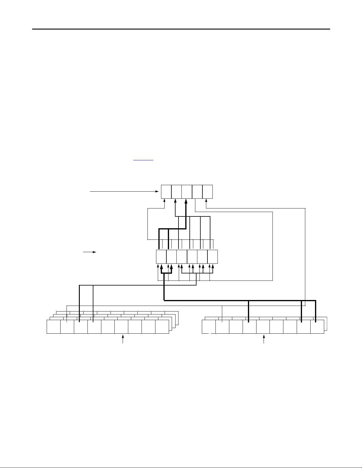
Module Features Chapter 3
Channel Fault Word
5 - I.Out1Fault
4 - I.Out0Fault
3 - I.In3Fault
2 - I.In2Fault
1 - I.In1Fault
0 - I.In0Fault
Input Channel Status Word
(one for each input channel)
8 - I.In[x].ChanFault (matches I.InxFault bits)
7 - I.In[x].CalFault
6 - I.In[x].Underrange
5 - I.In[x].Overrange
4 - I.In[x].RateAlarm
3 - I.In[x].LAlarm
2 - I.In[x].HAlarm
1 - I.In[x].LLAlarm
0 - I.In[x].HHAlarm
15 14 13 12 11
543210
543 2 1076
Module Fault Word
15 - I.AnalogGroupFault
14 - I.InGroupFault
13 - I.OutGroupFault
12 - I.Calibrating
11 - I.CalFault
If set, any bit (0…5) in the
Channel Fault word, also sets
the Analog Group Fault bit (15)
in the Module Fault word.
If set, the
calibration
fault (7)sets
the I.CalFault
bit (11) in the
Module Fault
word.
When the
module is
calibrating, for
example bit 12
is set, all bits
(0…5) in the
Channel Fault
word are set.
43162
8
543 2 10768
Output Channel Status Word
(one for each output channel)
8 - I.Out[x].ChanFault (matches I.OutxFault bits)
7 - I.Out[x].CalFault
6 - NotUsed
5 - I.Out[x].WireOff
4 - I.Out[x].NotANumber
3 - I.Out[x].InHold
2 - I.Out[x].RampAlarm
1 - I.Out[x].LLimitAlarm
0 - I.Out[x].HLimitAlarm
If set, the input channel fault bits
(0…3) set the InGroupFault bit
(14) in the Module Fault word.
If set, the output channel fault
bits (4 or 5) set the
OutGroupFault bit (13) in the
Module Fault word.
If set, the high limit alarm (0), low limit alarm (1), and wire off (5)
bits set the OutxFault bit (4 or 5) in the Module Fault word.
If set, the overrange and underrange
bits (5 and 6) set the I.InxFault bits
(0…3) in the Module Fault word.
Fault and Status Reporting
The ControlLogix high-speed analog I/O module multicasts status/fault data to
the owner/listening controller with its channel data. The fault data is arranged so
that users can choose the level of granularity they desire for examining fault
conditions.
Three levels of tags work together to provide an increasing degree of detail as to
the specific cause of faults on the module:
·Module Fault word—Provides fault summary reporting.
·Channel Fault word—Provides notification that a fault has occurred on
individual channels.
· Channel Status word (one for input and one for output channels)—
Provides notification of specific types of faults occurring on individual
channels.
Figure 9
provides an overview of the fault reporting process in the ControlLogix
high-speed analog I/O module.
Figure 9 - Fault Reporting
Rockwell Automation Publication 1756-UM005B-EN-P - January 2013 49
Page 50
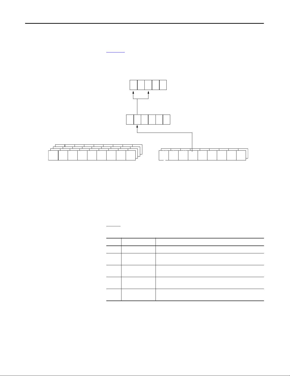
Chapter 3 Module Features
15 14 13 12 11
5 4 3210
5 4321076
When set, the I.Out0Fault bit (bit 4) sets the I.OutGroupFault bit (bit 13) and the
I.AnalogGroupFault bit (bit 15).
43175
8
When set, I.Out[0].WireOff bit sets the I.Out0Fault bit (bit 4) in the
Channel Fault word.
When the Wire Off condition on channel 0 occurs, the I.Out[0].WireOff bit (bit 5) in the
Output Channel Status word is set.
543210768
Fault Reporting Example
Figure 10 shows an example of what bits are set when a ControlLogix high-speed
analog I/O module reports a Wire Off condition on output channel 0. Three
events occur, beginning in the Output Channel Status word.
Figure 10 - Fault Reporting for Wire Off Condition
The following sections provide a listing and explanation of the bits included in
each of the module’s fault reporting words.
Module Fault Word Bits
Ta b l e 8 defines the Module Fault word bits.
Table 8 - Module Fault Word Bit Descriptions
Bit Name Description
Bit 15 I.AnalogGroupFault Bit is set when any of the bits in the Channel Fault word are set.
Bit 14 I.InGroupFault Bit is set when any of the input channel fault bits in the Channel Fault word are
Bit 13 I.OutGroupFault B it is set when any of the output channel fault bits in the Channel Fault word are
Bit 12 I.Calibrating Bit is set when any of the module’s channels are being calibrated. When this bit is
Bit 11 I.CalFault Bit is set when an individual channel calibration fault bit, such as I.In[0].CalFault,
set.
set.
set, all used bits in the Channel Fault word are set.
is set.
50 Rockwell Automation Publication 1756-UM005B-EN-P - January 2013
Page 51

Channel Fault Word Bits
Ta b l e 9 defines the Channel Fault word bits.
Table 9 - Channel Fault Word Bit Des cripti ons
Bit Name Description
Bit 5 I.Out1Fault Bit is set if any of the following events occurs:
• The module is being calibrated.
• A communication fault occurs between the module and its owner-controller.
• Wire off condition exists on output channel 1.
• Low limit alarm is set on output channel 1.
• High limit alarm is set on output channel 1.
Bit 4 I.Out0Fault Bit is set if any of the following events occurs:
• The module is being calibrated.
• A communication fault occurs between the module and its owner-controller.
• Wire off condition exists on output channel 0.
• Low limit alarm is set on output channel 0.
• High limit alarm is set on output channel 0.
Bit 3 I.In3Fault Bit is set if any of the following events occurs:
• The module is being calibrated.
• A communication fault occurs between the module and its owner-controller.
• An underrange condition exists on input channel 3.
• An overrange condition exists on input channel 3.
Bit 2 I.In2Fault Bit is set if any of the following events occurs:
• The module is being calibrated.
• A communication fault occurs between the module and its owner-controller.
• An underrange condition exists on input channel 2.
• An overrange condition exists on input channel 2.
Bit 1 I.In1Fault Bit is set if any of the following events occurs:
• The module is being calibrated.
• A communication fault occurs between the module and its owner-controller.
• An underrange condition exists on input channel 1.
• An overrange condition exists on input channel 1.
Bit 0 I.In0.Fault Bit is set if any of the following events occurs:
• The module is being calibrated.
• A communication fault occurs between the module and its owner-controller.
• An underrange condition exists on input channel 0.
• An overrange condition exists on input channel 0.
Module Features Chapter 3
Rockwell Automation Publication 1756-UM005B-EN-P - January 2013 51
Page 52

Chapter 3 Module Features
Input Channel Status Word Bits
Ta b l e 1 0 defines the Input Channel Status word bits.
Table 10 - Input Channel Status Word Bit Description
Bit Name Description
Bit 8 I.In[x].ChanFault This bit matches the state of I.InxFault bits (0-3) in the Channel Fault word, except
when a communication fault occurs. If a communication fault occurs between the
module and its owner-controller, the I.InxFault bit is set but this bit is not set.
Bit is set if one of the following events occurs:
• The module is being calibrated.
• An underrange condition exists on input channel.
• An overrange condition exists on input channel.
Bit 7 I.In[x].CalFault Bit is set if an error occurs, and is not corrected, during calibratio n for that channel.
Bit 6 I.In[x].Underrange Bit is set when the input signal at the channel is less than or equal to the
minimum detectable signal.
Bit 5 I.In[x].Overrange Bit is set when the input signal at the channel is greater than or equal to the
maximum detectable signal.
Bit 4 I.In[x].RateAlarm Bit is set when the input channel’s rate of change exceeds the configured Rate
Alarm parameter. It remains set until the rate of change drops below the
configured rate. If latched, the alarm will remain set until it is unlatched.
Bit 3 I.In[x].LAlarm Bit is set when the input signal moves beneath the configured Low Alarm limit. It
remains set until the signal moves above the limit. If latched, the alarm remains
set until it is unlatched. If a deadband is specified, the alarm also remains set as
long as the signal remains within the configured deadband.
Bit 2 I.In[x].HAlarm Bit is set when the input signal moves above the configured High Alarm limit. It
remains set until the signal moves below the limit. If latched, the alarm remains
set until it is unlatched. If a deadband is specified, the alarm also remains set as
long as the signal remains within the configured deadband.
Bit 1 I.In[x].LLAlarm Bit is set when the input signal moves beneath the configured Low-Low Alarm
limit. It remains set until the signal moves above the limit. If latched, the alarm
remains set until it is unlatched. If a deadband is specified, the alarm also remains
latched as long as the signal remains within the configured deadband.
Bit 0 I.In[x].HHAlarm Bit is set when the input signal moves above the configured High-High Alarm
limit. It remains set until the signal moves below the limit. If latched, the alarm
remains set until it is unlatched. If a deadband is specified, the alarm also remains
latched as long as the signal remains within the configured deadband.
52 Rockwell Automation Publication 1756-UM005B-EN-P - January 2013
Page 53

Module Features Chapter 3
Output Channel Status Word Bits
Ta b l e 1 1 defines the Output Channel Status word bits.
Table 11 - Output Channel Status Word Bit Descriptions
Bit Name Description
Bit 8 I.Out[x].ChanFault This bit matches the state of I.OutxFault bits (4 & 5) in the Channel Fault word, except
Bit 7 I.Out[x].CalFault Bit is set if an error occurs, and is not corrected, during calibration for that channel.
Bit 5 I.Out[x].WireOff Bit is set only if the configured Output Range is 0…20 mA, and the circuit becomes
Bit 4 I.Out[x].NotANumber Bit is set when the output value received from the controller is not a number (the
Bit 3 I.Out[x].InHold Bit is set when the output channel is currently holding. The bit resets when the
Bit 2 I.Out[x].RampAlarm Bit is set when the output channel’s requested rate of change would exceed the
Bit 1 I.Out[x].LLimitAlarm Bit is set when the requested output value is beneath the configured low l imit value.
Bit 0 I.Out[x].HLimitAlarm Bit is set when the requested output value is above the configured high limit value. It
when a communication fault occurs. If a communication fault occurs between the
module and its owner-controller, the I.OutxFault bit is set but this bit is not set.
Bit is set if one of the following events occurs:
• The module is being calibrated.
• Low limit alarm is set on the output channel.
• High limit alarm is set on the output channel.
open due to a wire falling or being cut when the output being driven is above
0.1 mA. The bit will remain set until correct wiring is restored.
IEEE NAN value). In this case, the output channel holds its last state.
requested Run mode output value is within 0.1% of full-scale of the current echo
value.
configured maximum ramp rate. It remains set until the output reaches its target
value and ramping stops. If the bit is latched, it remains set until it is unlatched.
It remains set until the requested output is above the low limit. If the bit is latched, it
remains set until it is unlatched.
remains set until the requested output is below the high limit. If the bit is latched, it
remains set until it is unlatched.
Rockwell Automation Publication 1756-UM005B-EN-P - January 2013 53
Page 54

Chapter 3 Module Features
Notes:
54 Rockwell Automation Publication 1756-UM005B-EN-P - January 2013
Page 55

Install the Module
Top ic Pag e
Install the Module 57
Key the Removable Terminal Block 59
Connect the Wiring 60
Wire the Module 63
Assemble the Removable Terminal Block and the Housing 66
Install the Removable Terminal Block onto the Module 67
Remove the Removable Terminal Block from the Module 68
Remove the Module from the Chassis 69
Chapter 4
ATTENTION: Environment and Enclosure
This equipment is intended for use in a Pollution Degree 2 industrial environment, in overvoltage Category II applications (as
defined in IEC 60664-1), at altitudes up to 2000 m (6562 ft) without derating.
This equipment is not intended for use in residential environments and may not provide adequate protection to radio
communication services in such environments.
This equipment is supplied as open-type equipment. It must be mounted within an enclosure that is suitably designed for those
specific environmental conditions that will be present and appropriately designed to prevent personal injury resulting from
accessibility to live parts. The enclosure must have suitable flame-retardant properties to prevent or minimize the spread of
flame, complying with a flame spread rating of 5VA or be approved for the application if nonmetallic. The interior of the
enclosure must be accessible only by the use of a tool. Subsequent sections of this publication may contain additional
information regarding specific enclosure type ratings that are required to comply with certain product safety certifications.
In addition to this publication, see the following:
• Industrial Automation Wiring and Grounding Guidelines, publication 1770-4.1
, for additional installation requirements
• NEMA Standard 250 and IEC 60529, as applicable, for explanations of the degrees of protection provided by enclosures
Rockwell Automation Publication 1756-UM005B-EN-P - January 2013 55
Page 56
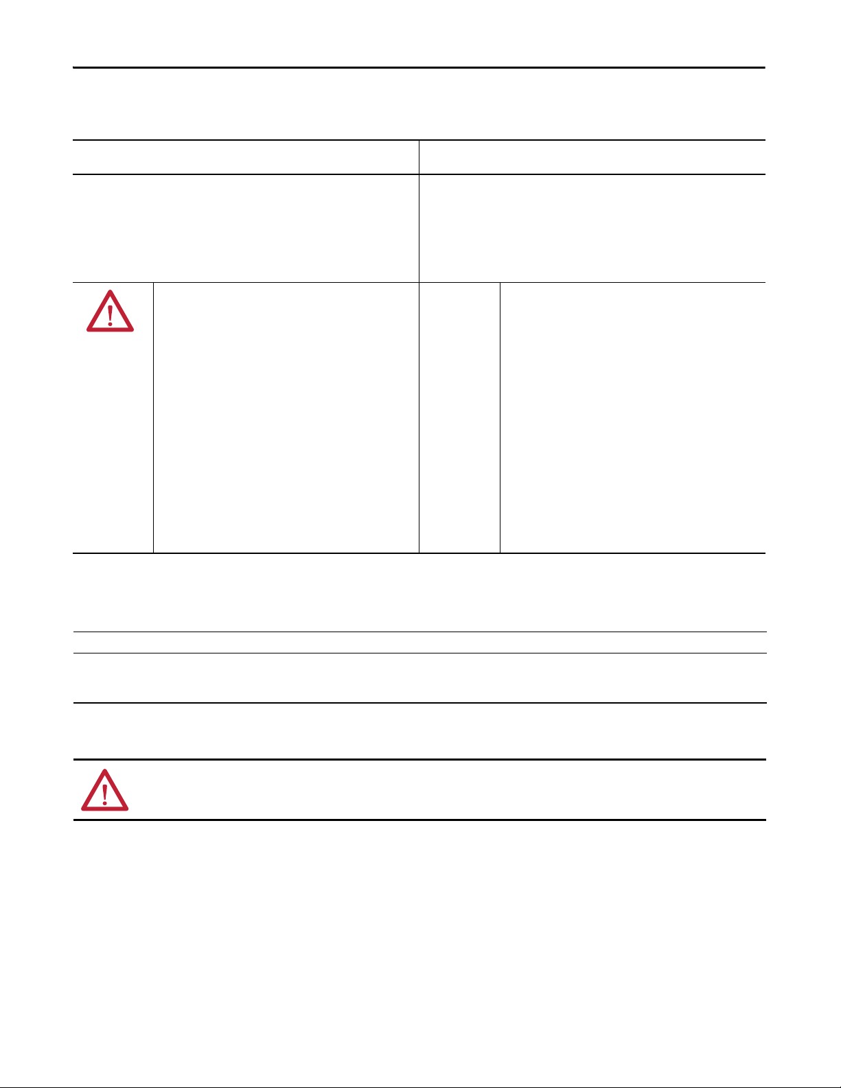
Chapter 4 Install the Module
North American Hazardous Location Approval
The following information applies when operating this equipment in
hazardous locations.
Products marked "CL I, D IV 2, GP A, B, C, D" are suitable for use in Class I Division 2 Groups
A, B, C, D, Hazardous Locations and nonhazardous locations only. Each product is supplied
with markings on the rating nameplate indicating the hazardous location temperature
code. When combining products within a system, the most adverse temperature code
(lowest "T" number) may be used to help determine the overall temperature code of the
system. Combinations of equipment in your system are subject to investigation by the
local Authority Having Jurisdiction at the time of installation.
Informations sur l’utilisation de cet équipement en environnements
dangereux.
Les produits marqués "CL I, DIV 2, GP A, B, C, D" ne conviennent qu'à une utilisation en
environnements de Classe I Division 2 Groupes A, B, C, D dangereux et non dangereux.
Chaque produit est livré avec des marquages sur sa plaque d'identification qui indiquent
le code de température pour les environnements dangereux. Lorsque plusieurs produits
sont combinés dans un système, le code de température le plus défavorable (code de
température le plus faible) peut être utilisé pour déterminer le code de température
global du système. Les combinaisons d'équipements dans le système sont sujettes à
inspection par les autorités locales qualifiées au moment de l'installation.
WARNING: EXPLOSION HAZARD
• Do not disconnect equipment unless power has
been removed or the area is known to be
nonhazardous.
• Do not disconnect connections to this
equipment unless power has been removed or
the area is known to be nonhazardous. Secure
any external connections that mate to this
equipment by using screws, sliding latches,
threaded connectors, or other means provided
with this product.
• Substitution of components may impair
suitability for Class I, Division 2.
• If this product contains batteries, they must only
be changed in an area known to be
nonhazardous.
European Hazardous Location Approval
The following applies when the product bears the Ex Marking.
This equipment is intended for use in potentially explosive atmospheres as defined by European Union Directive 94/9/EC and has been found to comply with the Essential Health and
Safety Requirements relating to the design and construction of Category 3 equipment intended for use in Zone 2 potentially explosive atmospheres, given in Annex II to this Directive.
Compliance with the Essential Health and Safety Requirements has been assured by compliance with EN 60079-15 and EN 60079-0.
WARNING: RISQUE D’EXPLOSION
• Couper le courant ou s'assurer que
l'environnement est classé non dangereux avant
de débrancher l'équipement.
• Couper le courant ou s'assurer que
l'environnement est classé non dangereux avant
de débrancher les connecteurs. Fixer tous les
connecteurs externes reliés à cet équipement à
l'aide de vis, loquets coulissants, connecteurs
filetés ou autres moyens fournis avec ce produit.
• La substitution de composants peut rendre cet
équipement inadapté à une utilisation en
environnement de Classe I, Division 2.
• S'assurer que l'environnement est classé non
dangereux avant de changer les piles.
ATTENTION: This equipment is not resistant to sunlight or other sources of UV radiation.
56 Rockwell Automation Publication 1756-UM005B-EN-P - January 2013
Page 57
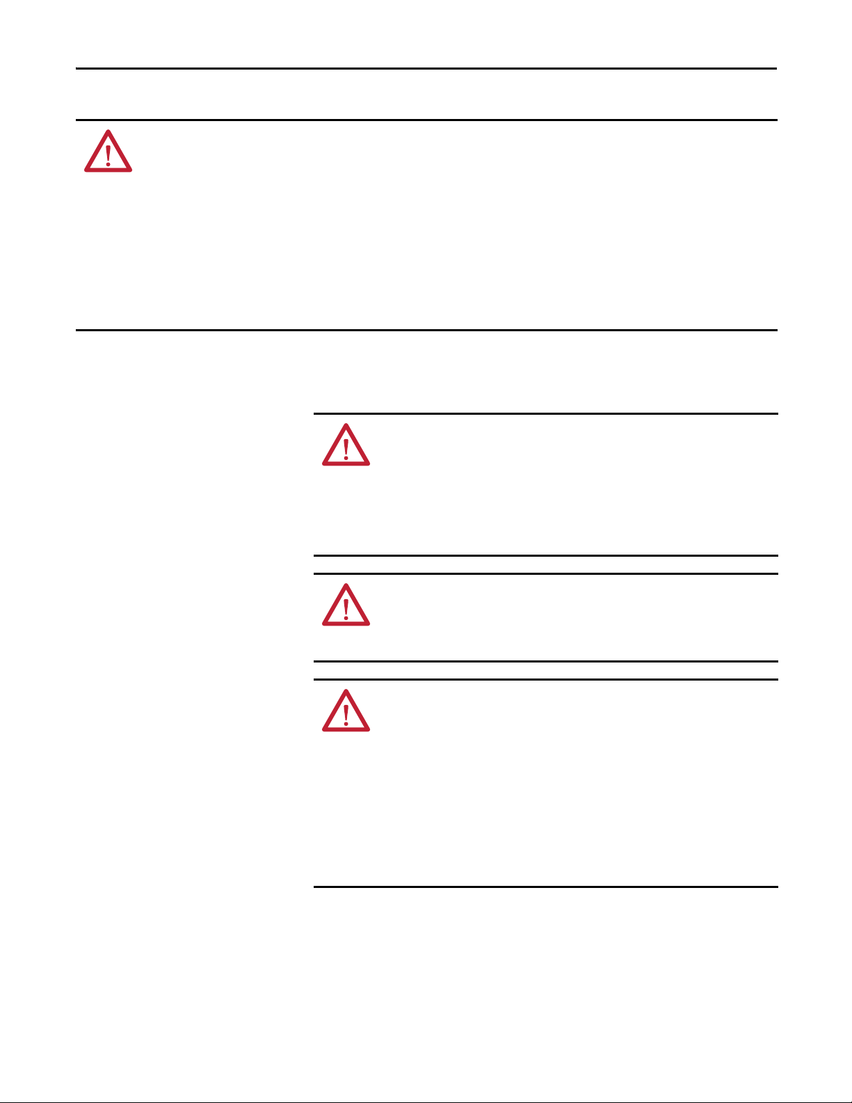
Install the Module Chapter 4
WARNING:
• This equipment shall be mounted in an ATEX certified enclosure with a minimum ingress protection rating of at least IP54
(as defined in IEC60529) and used in an environment of not more than Pollution Degree 2 (as defined in IEC 60664-1) when
applied in Zone 2 environments. The enclosure must utilize a tool removable cover or door.
• This equipment shall be used within its specified ratings defined by Rockwell Automation.
• Provision shall be made to prevent the rated voltage from being exceeded by transient disturbances of more than 140% of
the rated voltage when applied in Zone 2 environments.
• This equipment must be used only with ATEX certified Allen-Bradley® backplanes.
• Secure any external connections that mate to this equipment by using screws, sliding latches, threaded connectors, or other
means provided with this product.
• Do not disconnect equipment unless power has been removed or the area is known to be nonhazardous.
Install theModule
You can install or remove the module while chassis power is applied.
WARNING: When you insert or remove the module while backplane power is
on, an electrical arc can occur. This could cause an explosion in hazardous
location installations.
Be sure that power is removed or the area is nonhazardous before proceeding.
Repeated electrical arcing causes excessive wear to contacts on both the module
and its mating connector. Worn contacts may create electrical resistance that can
affect module operation.
WARNING: When you connect or disconnect the Removable Terminal Block
(RTB) with field side power applied, an electrical arc can occur. This could cause
an explosion in hazardous location installations.
Be sure that power is removed or the area is nonhazardous before proceeding.
ATTENTION: Prevent Electrostatic Discharge
This equipment is sensitive to electrostatic discharge, which can cause internal
damage and affect normal operation. Follow these guidelines when you handle
this equipment:
• Touch a grounded object to discharge potential static.
• Wear an approved grounding wriststrap.
• Do not touch connectors or pins on component boards.
• Do not touch circuit components inside the equipment.
• Use a static-safe workstation, if available.
• Store the equipment in appropriate static-safe packaging when not in use.
Rockwell Automation Publication 1756-UM005B-EN-P - January 2013 57
Page 58

Chapter 4 Install the Module
20861-M
Printed Circuit Board
20862-M
Locking Tab
1. Align the circuit board with the top and bottom chassis guides.
2. Slide the module into the chassis until module tabs click.
58 Rockwell Automation Publication 1756-UM005B-EN-P - January 2013
Page 59

Install the Module Chapter 4
20850-M
U-shaped Keying Band
20851–M
1
2
0
3
4
5
6
7
Wedg e-sh aped Key ing Tab
Module Side of RTB
IMPORTANT
Key the Removable Termin al B loc k
Wedge-shaped keying tabs and U-shaped keying bands came with your RTB to
prevent connecting the wrong wires to your module.
Key positions on the module that correspond to unkeyed positions on the RTB.
For example, if you key the first position on the module, leave the first position
on the RTB unkeyed.
1. Insert the U-shaped band as shown.
2. Push the band until it snaps in place.
3. Insert the wedge-shaped tab with rounded edge first.
4. Push the tab until it stops.
When keying your RTB and module, you must begin with a wedge-shaped tab
in position 6 or 7.
Rockwell Automation Publication 1756-UM005B-EN-P - January 2013 59
Page 60

Chapter 4 Install the Module
Connect the Wiring
You can use an RTB or a Bulletin 1492 prewired Interface Module (IFM) to
connect wiring to your module. An IFM has been prewired before you received
it. If you are using an IFM to connect wiring to the module, skip this section and
move to page 67
.
If you are using an RTB, connect wiring as directed below. We recommend you
use Belden 8761 cable to wire the RTB. The RTB terminations can
accommodate 22…14 AWG shielded wire.
Before wiring the RTB, you must connect ground wiring.
WARNING: If you connect or disconnect wiring while the field-side power is on,
an electrical arc can occur. This could cause an explosion in hazardous location
installations. Be sure that power is removed or the area is nonhazardous before
proceeding.
ATT EN TI ON : When using the 1756-TBCH RTB, do not wire more than two
2
0.33...1.3 mm
(22...16 AWG) conductors on any single terminal. Use only the
same size wires with no intermixing of solid and stranded wire types.
When using the 1756-TBS6H RTB, do not wire more than one conductor on any
single terminal.
60 Rockwell Automation Publication 1756-UM005B-EN-P - January 2013
Page 61

Connect the Grounded End of the Cable
IMPORTANT
20104-M
a. Remove a length of cable
jacket from the Belden cable.
b. Pull the foil shield and bare drain
wire from the insulated wire.
c. Twist the foil shield and drain
wiretogether to form a single
strand.
d. Attach a ground lug and apply
heat shrink tubing to the exit
area.
20918-M
e. Connect the drain wire to a chassis
mounting tab. Use any chassis
mounting tab that is designated as a
functional signal ground.
4M or 5M (#10 or #12)
Star Washer
4M or 5M (#10 or #12)
Phillips Screw and Star
Washer (for SEM screw)
Chassis Mounting Tab
Drain Wire with Ground Lug
1. Ground the drain wire.
We recommend you ground the drain wire at the field-side. If you
cannot ground at the field-side, ground at an earth ground on the
chassis as shown below.
Install the Module Chapter 4
2. Connect the insulated wires to the field-side.
Connect Ungrounded End of the Cable
1. Cut the foil shield and drain wire back to the cable casing and apply shrink
wrap.
2. Connect the insulated wires to the RTB, as shown below.
Rockwell Automation Publication 1756-UM005B-EN-P - January 2013 61
Page 62

Chapter 4 Install the Module
20859-M
Strain Relief Area
20860-M
Strain Relief Area
Two Types of RTBs (each RTB comes with housing)
ATT EN TI ON : The ControlLogix system has been agency certified using only the
ControlLogix RTBs (catalog numbers 1756-TBCH and 1756-TBS6H). Any
application that requires agency certification of the ControlLogix system using
other wiring termination methods may require application specific approval by
the certifying agency.
Cage Clamp - Catalog Number 1756-TBCH
1. Insert the wire into the terminal.
2. Turn the screw clockwise to close the terminal on the wire.
Spring Clamp - Catalog Number 1756-TBSH or TBS6H
1. Insert the screwdriver into the outer hole of the RTB.
2. Insert the wire into the open terminal and remove the screwdriver.
62 Rockwell Automation Publication 1756-UM005B-EN-P - January 2013
Page 63

Install the Module Chapter 4
12
34
56
78
910
1112
1314
1516
1718
1920
2122
2324
2526
2728
2930
3132
3334
3536
+IN-1/V
IN-1/I
-IN-1
+IN-3/V
V OUT-1
IN-3/I
-IN-3
Not Used
Not Used
I OUT-1
RTN-1
2-wire
Transmitter
(+) (-)
i
42742
Shield Ground
Current
Output
Load
= Inline Field Device (strip chart recorder or meter)
A
A
A
Not Used
Not Used
Not Used
Not Used
Not Used
Not Used
Not Used
Not Used
Not Used
Not Used
Not Used
Not Used
Not Used
Not Used
+IN-0/V
IN-0/I
-IN-0
+IN-2/V
V OUT-0
IN-2/I
-IN-2
Not Used
Not Used
I OUT-0
RTN-0
Recommendations for Wiring Your RTB
We recommend you follow these guidelines when wiring your RTB.
1. Begin wiring the RTB at the bottom terminals and move up.
2. Use a tie to secure the wires in the strain relief area of the RTB.
3. Order and use an extended-depth housing (catalog number 1756-TBE) for
applications that require heavy gauge wiring.
Wire the Module
Use the wiring diagrams below to wire your ControlLogix high-speed analog I/O
module.
Figure 11 - 1756-IF4FXOF2F Current Mode Wiring Diagram
Rockwell Automation Publication 1756-UM005B-EN-P - January 2013 63
Page 64
Chapter 4 Install the Module
12
34
56
78
910
1112
1314
1516
1718
1920
2122
2324
2526
2728
2930
3132
3334
3536
+IN-1/V
IN-1/I
-IN-1
+IN-3/V
V OUT-1
IN-3/I
-IN-3
Not Used
Not Used
I OUT-1
RTN-1
4-wire
Transmitter
(+)
(-)
i
42742
Shield Ground
Current
Output
Load
= Inline Field Device (strip chart recorder or meter)
A
A
A
Not Used
Not Used
Not Used
Not Used
Not Used
Not Used
Not Used
Not Used
Not Used
Not Used
Not Used
Not Used
Not Used
Not Used
+IN-0/V
IN-0/I
-IN-0
+IN-2/V
V OUT-0
IN-2/I
-IN-2
Not Used
Not Used
I OUT-0
RTN-0
Figure 12 - 1756-IF4FXOF2F Current Mode Wiring Diagram
64 Rockwell Automation Publication 1756-UM005B-EN-P - January 2013
Page 65
Figure 13 - 1756-IF4FXOF2F Voltage Mode Wiring Diagram
42743
+IN-1/V
IN-1/I
-IN-1
+IN-3/V
V OUT-1
IN-3/I
-IN-3
Not Used
Not Used
I OUT-1
RTN-1
Not Used
Not Used
Not Used
Not Used
Not Used
Not Used
Not Used
Not Used
Not Used
Not Used
Not Used
Not Used
Not Used
Not Used
+IN-0/V
IN-0/I
-IN-0
+IN-2/V
V OUT-0
IN-2/I
-IN-2
Not Used
Not Used
I OUT-0
RTN-0
(+)
(-)
Shield Ground
(+)
(-)
12
34
56
78
910
1112
1314
1516
1718
1920
2122
2324
2526
2728
2930
3132
3334
3536
Install the Module Chapter 4
Rockwell Automation Publication 1756-UM005B-EN-P - January 2013 65
Page 66
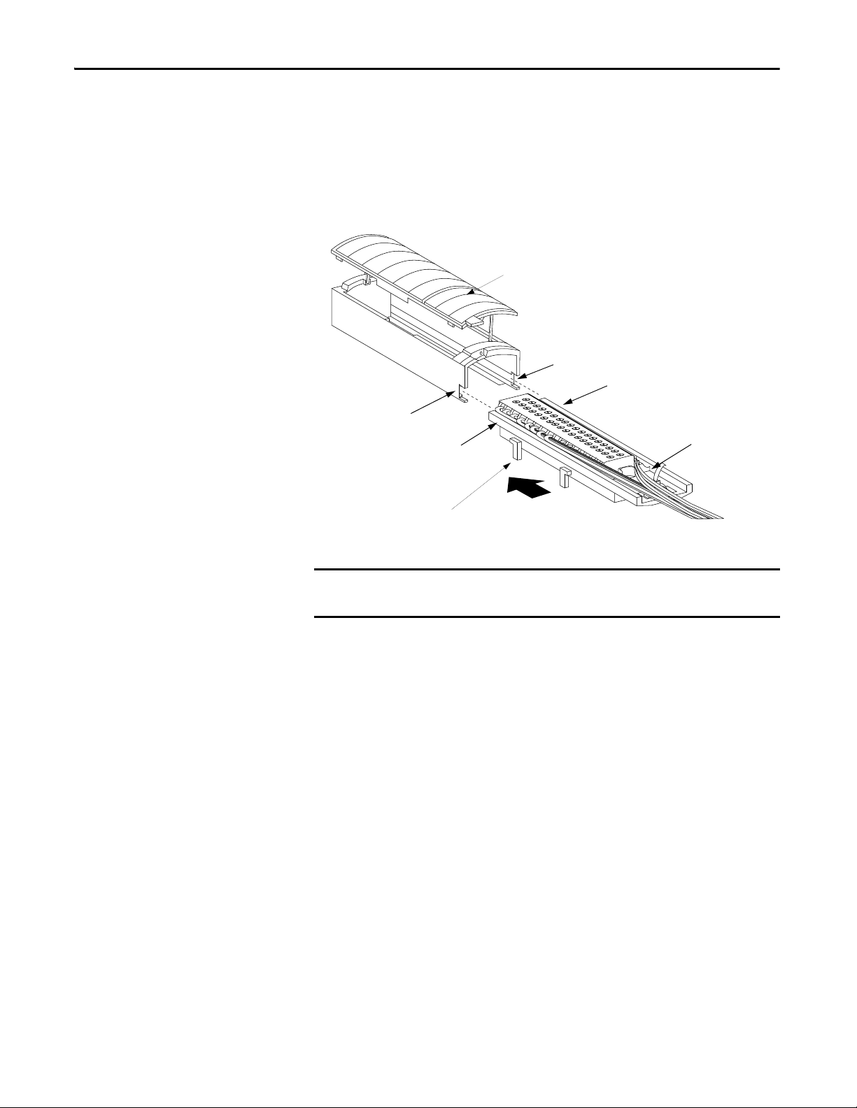
Chapter 4 Install the Module
20858-M
Housing
RTB
Groove
Side Edge of the RTB
Strain Relief Area
Groove
Side Edge of the RTB
IMPORTANT
Assemble the Removable Terminal Block and the Housing
Removable housing covers the wired RTB to protect wiring connections when
the RTB is seated on the module.
1. Align the grooves at the bottom of each side of the housing with the side
edges of the RTB.
2. Slide the RTB into the housing until it snaps into place.
If additional wire routing space is required for your application, use extendeddepth housing, catalog number 1756-TBE.
66 Rockwell Automation Publication 1756-UM005B-EN-P - January 2013
Page 67
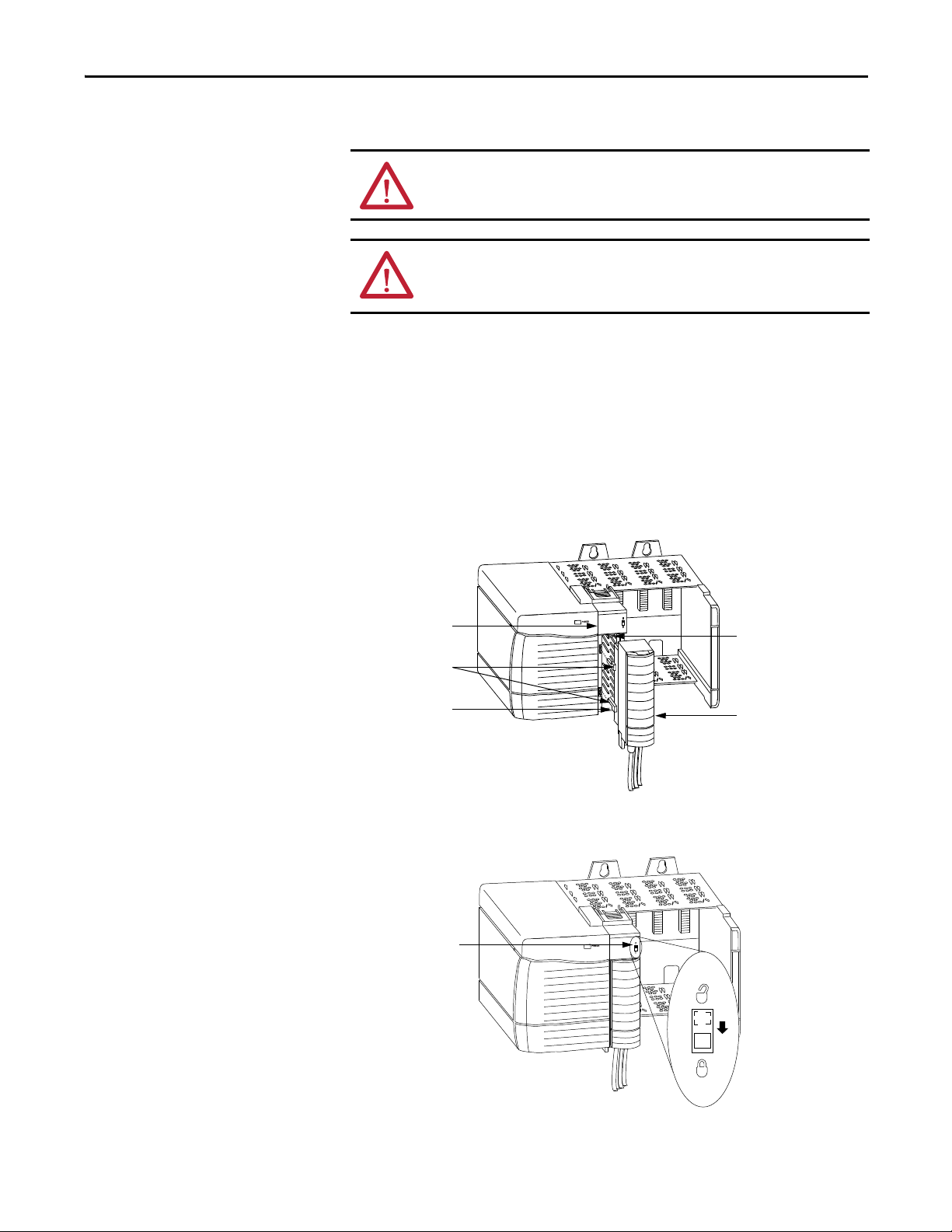
Install the Module Chapter 4
20853-M
RTB
Module
Bottom Guide
Left-side Guides
Top Gu ide
20854-M
Locking Tab
Install the Removable Terminal Block onto the Module
Install the RTB onto the module to connect wiring.
ATT EN TI ON : Be sure that power is removed or the area is nonhazardous before
proceeding.
WARNING: When you connect or disconnect the Removable Terminal Block
(RTB) with field side power applied, an electrical arc can occur. This could cause
an explosion in hazardous location installations.
Before installing the RTB, make sure of the following:
• The field-side wiring of the RTB has been completed.
• The RTB housing is snapped into place on the RTB.
• The RTB housing door is closed.
• The locking tab at the top of the module is unlocked.
1. Align the top, bottom, and left-side guides on the RTB with matching
guides on the module.
2. Press quickly and evenly to seat the RTB on the module until the latches
snap into place.
3. Slide the locking tab down to lock the RTB onto the module.
Rockwell Automation Publication 1756-UM005B-EN-P - January 2013 67
Page 68
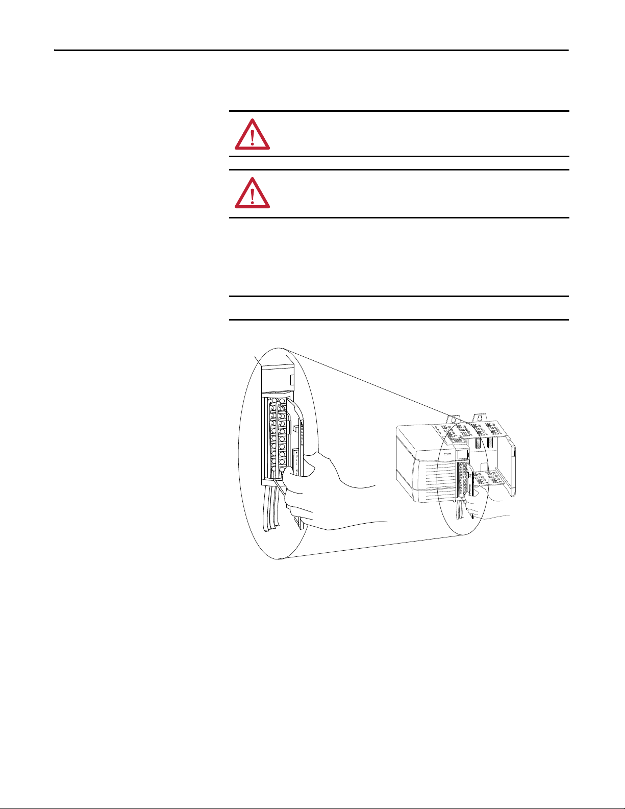
Chapter 4 Install the Module
IMPORTANT
20855-M
Remove the Removable Terminal Block from the Module
If you need to remove the module from the chassis, you must first remove the
RTB from the module.
ATT EN TI ON : Be sure that power is removed or the area is nonhazardous before
proceeding.
WARNING: When you connect or disconnect the Removable Terminal Block
(RTB) with field side power applied, an electrical arc can occur. This could cause
an explosion in hazardous location installations.
1. Unlock the locking tab at the top of the module.
2. Open the RTB door using the bottom tab.
3. Hold the spot marked PULL HERE and pull the RTB off the module.
Do not wrap your fingers around the entire door. A shock hazard exists.
68 Rockwell Automation Publication 1756-UM005B-EN-P - January 2013
Page 69
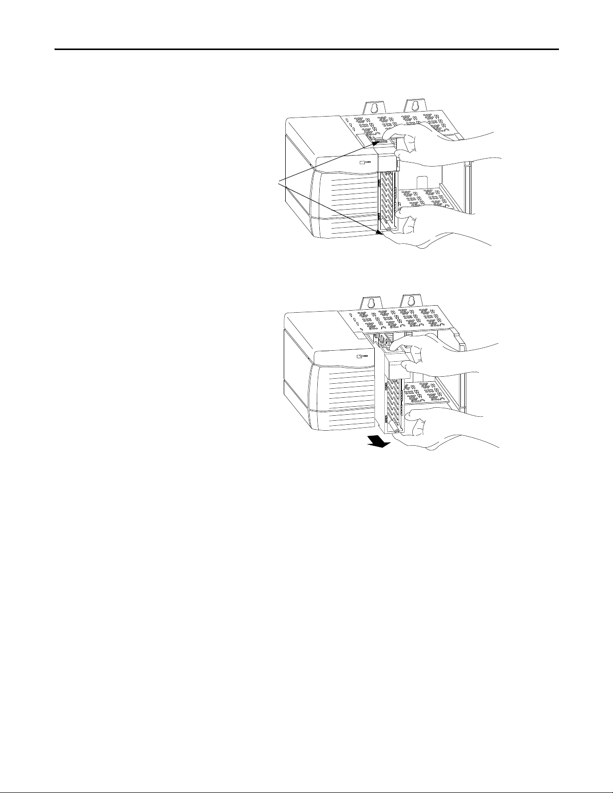
Install the Module Chapter 4
20856-M
Locking Tabs
20857-M
Remove the Module from the Chassis
1. Push in the top and bottom locking tabs.
2. Pull module out of the chassis.
Rockwell Automation Publication 1756-UM005B-EN-P - January 2013 69
Page 70

Chapter 4 Install the Module
Notes:
70 Rockwell Automation Publication 1756-UM005B-EN-P - January 2013
Page 71

Configure the Module
IMPORTANT
Top ic Pag e
Overview of the Configuration Process 72
Create a New Module 73
Use the Default Configuration 75
Alter the Default Configuration 76
Download New Configuration Data 79
Edit the Configuration 80
Reconfigure Module Parameters in Run Mode 81
Reconfigure Module Parameters in Program Mode 82
View and Change ModuleTags 83
Chapter 5
You must configure your module upon installation. The module does not work
until it has been configured.
This chapter focuses on configuring high-speed analog I/O modules in a local
chassis. To configure high-speed analog I/O modules in a remote chassis, see
Appendix
E.
Use the Logix Designer application to configure your ControlLogix high-speed
analog I/O module. You can accept the default configuration for your module or
specify a custom, point-level configuration specific to your application.
Rockwell Automation Publication 1756-UM005B-EN-P - January 2013 71
Page 72
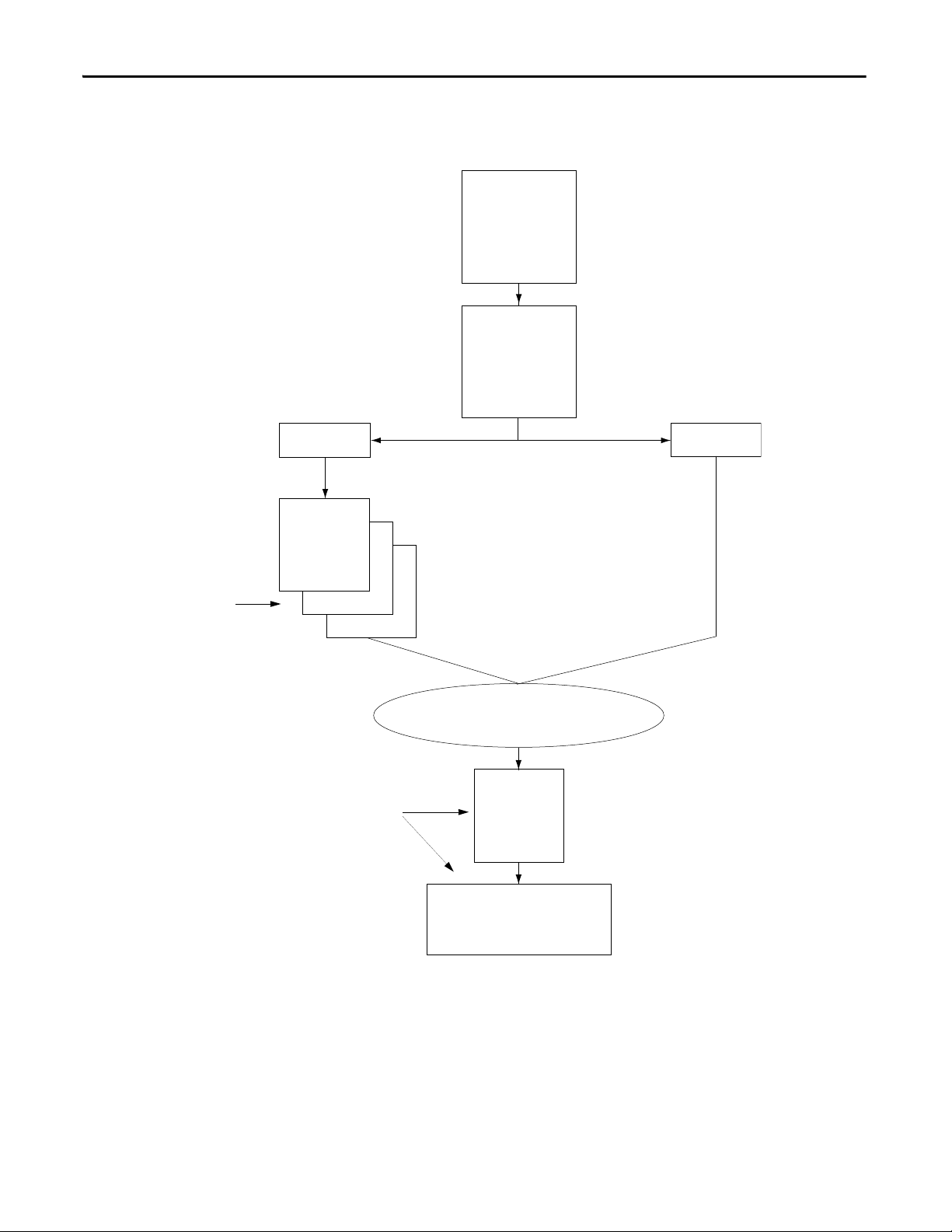
Chapter 5 Configure the Module
1.Select the
high-speed analog I/O
module.
2.Choose a major
revisio n.
Name
Description
Slot number
Communication format
minor revision
Keying choice
Series of
Application-specific
Parameters
Make custom
configuration
choices here.
A pop-up menu
leads to a
module’s
configuration
properties.
Edit a module’s
configuration here.
A series of tabs in the application
provide access to change a module’s
configuration data.
Click Next to use a
custom configuration.
Click Finish to use the
default configuration.
41058
Next Finish
Configuration Complete
General Tab
New Module
Overview of the Configuration Process
The following diagram shows an overview of the configuration process.
72 Rockwell Automation Publication 1756-UM005B-EN-P - January 2013
Page 73
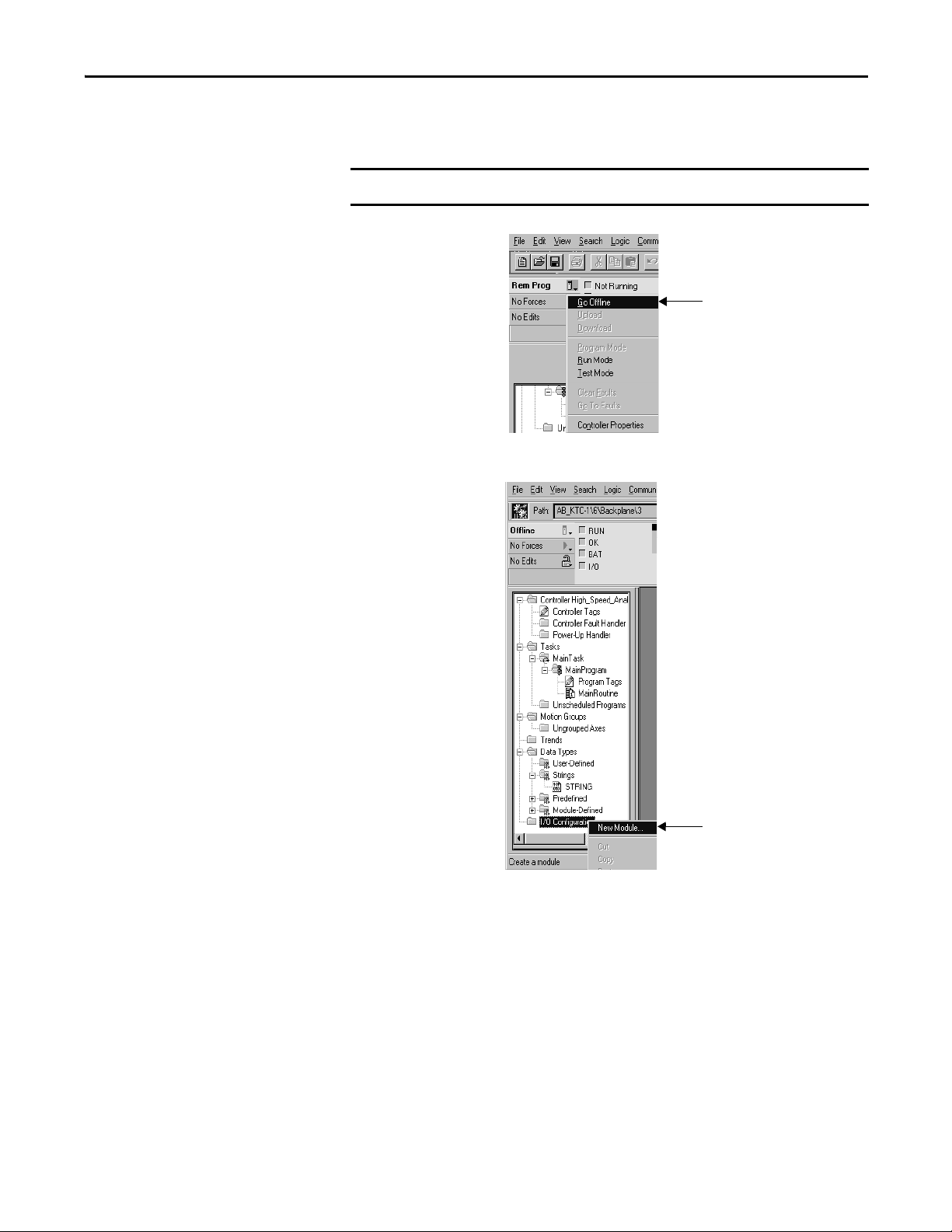
Configure the Module Chapter 5
IMPORTANT
Use this pull-down menu to go offline.
1. Select I/O Configuration.
2. Right-click to see the menu.
3. Choose New Module.
Create a New Module
After you have started the application and created a controller project, you must
create a new module. The wizard lets you create a new module and configure it.
You must be offline when you create a new module.
When you are offline, you must select a new module.
Rockwell Automation Publication 1756-UM005B-EN-P - January 2013 73
Page 74

Chapter 5 Configure the Module
Click OK.
Select the high-speed
analog I/O module.
Click OK.
Make sure the Major Revision
number matches the label on
the side of your module.
Choose an electronic keying
method. A detailed explanation
of this field is provided on
page 25
.
If you are using default configuration, click
here and you are finished configuring your
module. Go to page 79
.
If you are altering the
default configuration, click
Next. Go to page 76
.
Make sure the Minor Revision
number matches the label on
the side of your module.
Type a name and optional description.
Select the slot in which your
module resides.
Choose a communication format.
A detailed explanation of this field
is provided on page 75
.
A dialog box appears with a list of possible new modules for your application.
Yo u en te r t h e w i z ard on a n am in g p a ge .
74 Rockwell Automation Publication 1756-UM005B-EN-P - January 2013
Page 75

Configure the Module Chapter 5
IMPORTANT
Communication Format
The communication format determines the following:
• Available configuration options
• Type of data transferred between the module and its owner-controller
• Tags that are generated when the configuration is complete
• Connection between the controller writing configuration and the module
itself
Ta b l e 1 2
lists the possible communication format choices. In addition to the
description below, each format returns status data and rolling timestamp data.
Table 12 - Communication Formats on the High-speed Analog I/O Module
Format Definition
Archiving Connection Module stores 20 input data samples for each channel in the module’s on-board
Float Data Module returns floating point data.
CST Timestamped Float Data Module returns floating point data with the value of the system clock (from its local
Listen-only CST Timestamped
Float Data
Listen-only Float Data Module returns floating point data to a controller that does not own the module.
buffers before it sends the I/O data to the controller.
chassis) when the data is sampled.
Module returns floating point data with the value of the system clock from its local
chassis when the data is sampled to a controller that does not own the module.
Once the module is created, the communication format cannot be changed.
The module must be deleted and recreated.
Electronic Keying
When you write configuration for a module you can choose how specific the
keying must be when a module is inserted into a slot in the chassis. The following
electronic keying options are available:
Use the Default Configuration
• Compatible Module
• Disable Keying
• Exact Match
For more information on electronic keying, see page 25
.
If you use the default configuration and click Finish, you are done.
Rockwell Automation Publication 1756-UM005B-EN-P - January 2013 75
Page 76

Chapter 5 Configure the Module
Click Next to proceed.
Click Next to proceed.
This information is used during online
monitoring, but not initial configuration.
Adjust the requested packet interval (page 19
).
Inhibit (page 34
) the connection to the module.
This Fault box is empty when you are offline.
If a fault occurs while the module is online,
the type of fault will be displayed here.
If you want a Major Fault on the Controller to occur
if there is connection failure with the I/O module
while in Run mode, check this checkbox .
Alter the Default Configuration
You can specify a custom configuration by modifying a series of parameters on
the Module Properties dialog box.
76 Rockwell Automation Publication 1756-UM005B-EN-P - January 2013
Page 77

Configure the Module Chapter 5
Click Finish to accept the parameters
you have configured for your module.
Click Next to proceed.
Click Finish to accept the
parameters you have configured
for your module.
Click Next to proceed.
Click Finish to accept the
parameters you have configured
for your module.
Click Next to proceed.
Choose an input channel.
IMPORTANT: Set all the parameters
for each channel before proceeding.
Set the scaling (page 36
).
Set the RTS rate (page 18
).
This setting affects the entire
module, not just a single channel.
To use sub-millisecond values, type
values with a decimal point. For
example, to use 800 μS, type 0.8.
Choose a range for the input
(page 38
).
Set the digital filter time
(page 43
).
Choose an input channel.
IMPORTANT: Set all the parameters
for each channel before proceeding.
Set process alarms (page 44
).
During module operation, the Unlatch
buttons are enabled, once set. Click
the button to unlatch alarms.
Disable all alarms.
Latch process alarms
(page 44).
Latch the rate alarm
(page 45
).
Set the deadband
(page 44).
Set the rate alarm
(page 45
).
Choose an output channel.
IMPORTANT: Set all the parameters for
each channel before proceeding.
Set the scaling (page 36
).
Choose a range for the
output (page 46
).
If necessary, enable Hold
for Initialization (page 47
).
Synchronize module inputs
(page 45
).
Rockwell Automation Publication 1756-UM005B-EN-P - January 2013 77
Page 78

Chapter 5 Configure the Module
Click here to accept the
parameters you have configured
for your module
Click Next to proceed.
Click Finish to accept the
parameters you have configured
for your module.
Click Next to proceed.
Choose an output channel.
IMPORTANT: Set all the parameters
for each channel before proceeding.
Set the Program mode output state.
If you click User Defined Value, you
must type a value in the box. You can
also choose to ramp to the value.
Set the output state in
Fault mode.
Choose an output channel.
IMPORTANT: Set all the parameters
for each channel before proceeding.
Set the clamp limits (page 48
).
Pay attention to the clamp limits when
changing a channel from current to
voltage. The software does not
automatically account for the mode
change. You must also take into
account how changes may affect your
engineering units.
If necessary, check the Ramp in Run
Mode checkbox (page 47
).
If you check the Ramp in Run Mode
checkbox, you must type a ramp rate
(page 47
).
Disable all alarms.
Latch limit alarms
(page 48
).
Set the output state if communication
fails in Program mode.
78 Rockwell Automation Publication 1756-UM005B-EN-P - January 2013
Page 79

Configure the Module Chapter 5
Use this pull-down menu to
download the new configuration.
Confir m the downl oad.
Download New Configuration Data
After you have changed the configuration data for a module, the change does not
actually take affect until you download the new program, which contains that
information. This downloads the entire program to the controller overwriting
any existing programs.
The software verifies the download process with the following dialog box.
This completes the download process.
Rockwell Automation Publication 1756-UM005B-EN-P - January 2013 79
Page 80
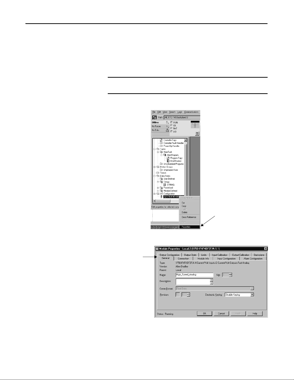
Chapter 5 Configure the Module
IMPORTANT
1. Select I/O Configuration.
2. Right-click to see the menu.
3. Choose Properties.
Click the tab associated
with the parameters to
view or reconfigure.
Edit the Configuration
After you set configuration for a module, you can review and change it. You can
change configuration data and download it to the controller while online. This is
called dynamic reconfiguration.
Your freedom to change some configurable features, though, depends on whether
the controller is in Remote Run mode or Program mode.
Although you can change configuration while online, you must go offline to
add or delete modules from the program.
The editing process begins on the main page.
80 Rockwell Automation Publication 1756-UM005B-EN-P - January 2013
The Module Properties dialog box appears as shown below.
Page 81
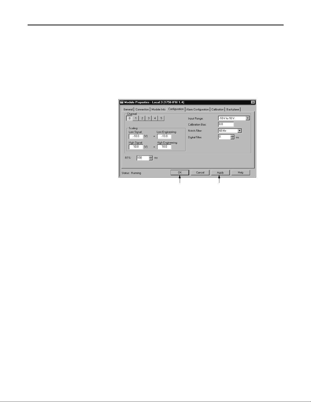
Configure the Module Chapter 5
Make the necessary configuration
changes. In this example, all
configurable features are enabled in
Run mode.
Click OK to transfer the new
data and close the dialog box.
Click Apply to transfer the new data
and keep the dialog box open.
Reconfigure Module Parameters in Run Mode
Your module can operate in Remote Run mode or Run mode. You can change
any configurable features that are enabled by the software only in Remote Run
mode.
If any feature is disabled in either Run mode, change the controller to Program
mode and make the necessary changes.
For example, the following example shows the configuration page while the
high-speed analog module is in Run mode.
Rockwell Automation Publication 1756-UM005B-EN-P - January 2013 81
Page 82
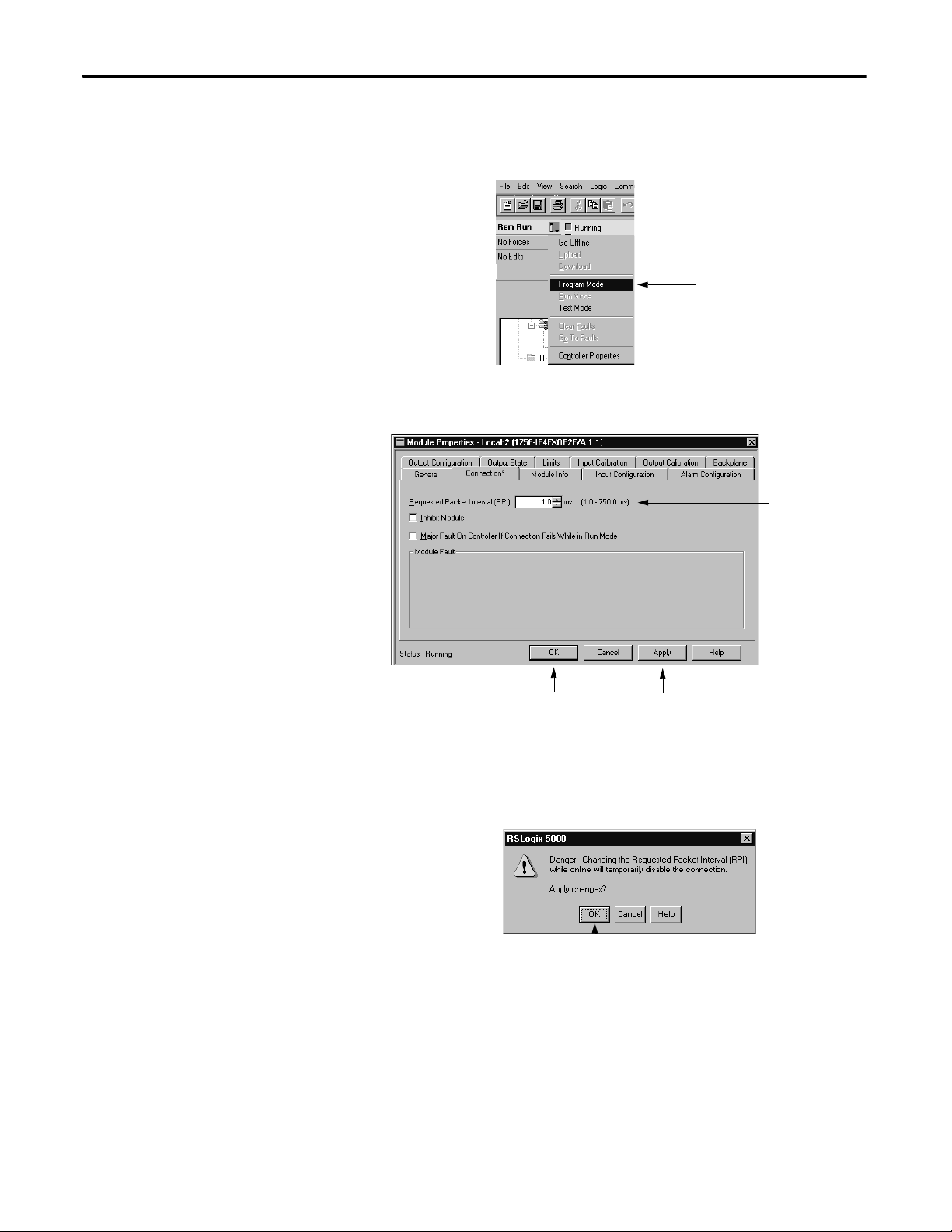
Chapter 5 Configure the Module
Use this pull-down menu to
switch to Program mode.
Click OK to transfer the new
data and close the dialog box.
Click Apply to transfer the new data
and keep the dialog box open.
Update the RPI rate.
Click OK to confirm the RPI change.
Reconfigure Module Parameters in Program Mode
Follow these steps to change configuration in Program mode.
1. Change the module from Run mode to Program mode, if necessary.
2. Make any necessary changes.
Before the RPI rate is updated online, the software verifies your desired
change.
The RPI is changed and the new configuration data is transferred to the
controller. After making the necessary changes to your module’s configuration in
Program mode, it is recommended that you change the module back to Run
mode.
82 Rockwell Automation Publication 1756-UM005B-EN-P - January 2013
Page 83
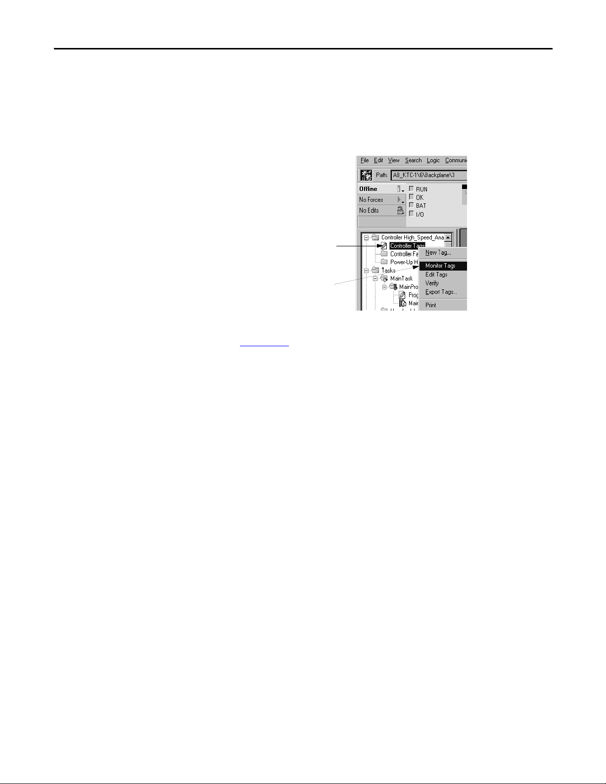
Configure the Module Chapter 5
Right-click Controller Tags
to see the menu.
Choose Monitor Tags.
View and Change Module Tags
When you create a module, the application creates a series of tags in the
ControlLogix system that can be viewed in the software’s tag editor. Each
configurable feature on your module has a distinct tag that can be used in the
processor’s ladder logic.
You can access a module’s tags through the software.
For more information about viewing and changing a module’s configuration tags
see, Appendix
B.
Rockwell Automation Publication 1756-UM005B-EN-P - January 2013 83
Page 84

Chapter 5 Configure the Module
Notes:
84 Rockwell Automation Publication 1756-UM005B-EN-P - January 2013
Page 85

Chapter 6
IMPORTANT
Calibrate the Module
Top ic Pag e
Differences for Each Channel Type 86
Calibrate Input Channels 87
Calibrate Output Channels 90
Your ControlLogix high-speed analog I/O module comes from the factory with a
default calibration. Use this chapter to recalibrate your module in the future.
You must add the module to your control program via the Logix Designer
application. Also, if you want to calibrate the module outputs, you must
configure an output range before calibrating the module.
To see how to add a new module to your program, see page 73
ControlLogix high-speed analog I/O modules allow you to calibrate each
channel individually or in groups, such as all inputs at once. Regardless of
which option you choose, we recommend you calibrate all channels on your
module each time you calibrate. This practice helps you maintain consistent
calibration readings and improve module accuracy.
Calibration is meant to correct any hardware inaccuracies that may be present
on a particular channel. The calibration procedure compares a known standard,
either input signal or recorded output, with the channel’s performance and
then calculates a linear correction factor between the measured and the ideal.
Also, we suggest you plug the module in and let it operate for at least 30
minutes before calibration to allow components to temperature stabilize. The
stability helps prevent temperature drift during operation.
.
Rockwell Automation Publication 1756-UM005B-EN-P - January 2013 85
Page 86
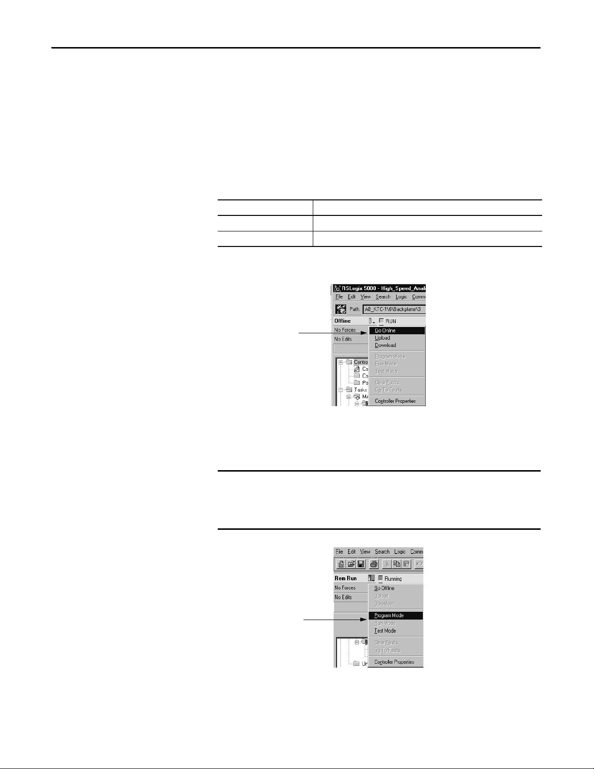
Chapter 6 Calibrate the Module
IMPORTANT
Use this pul l-down
menu to go online.
Use this pull-down menu to
change to Program Mode.
Differences for Each Channel Type
The procedures for calibrating input and output channels on the ControlLogix
high-speed analog I/O module vary slightly:
• For input channels, you use a voltage calibrator to send a signal to the
module to calibrate it.
• For output channels, you use a digital multimeter (DMM) to measure the
signal the module is sending out.
See the recommended instruments to use for each channel below.
Channel Type Recommended Instrument Ranges
Input 0…10.00V source ±500μV voltage
Output DMM better than 0.3 mV or 0.6 μA
You must be online to calibrate your high-speed analog I/O module.
When you are online, you can choose either Program or Run Mode as your
program state during calibration. We recommend that you change your controller
to Program mode before beginning calibration.
Before beginning calibration, make sure the module is not actively controlling
a process. The module freezes the state of each channel and does not update
the controller with new data until after calibration ends. This could be
hazardous if active control were attempted during calibration.
86 Rockwell Automation Publication 1756-UM005B-EN-P - January 2013
Page 87
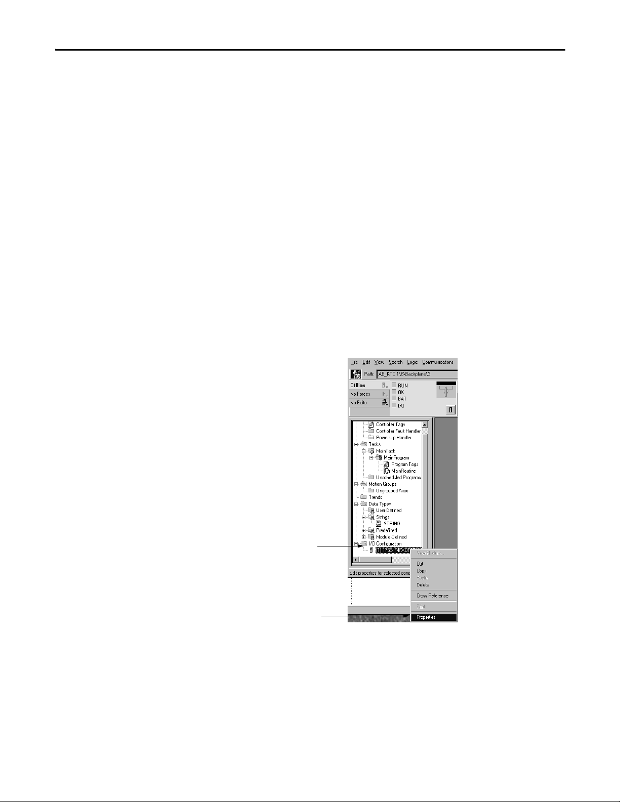
Calibrate the Module Chapter 6
Choose Properties.
Right-click I/O Configuration
to see the menu.
Calibrate Input Channels
Input calibration requires that you apply reference signals to the module’s input
channels and then verify the channel status. ControlLogix high-speed analog I/O
modules can operate in Current or Voltage mode. For voltage applications, you
need to calibrate only the -10…10V range. Calibrating to this range calibrates the
module for all other voltage ranges, such as 0…5V.
Regardless of mode, when calibrating the module’s inputs, you must do the
following:
• Apply a low signal to a channel (or group of channels)
• Verify the channel’s low signal reference
• Apply a high signal to a channel
• Verify the channel’s high signal reference
The following example shows calibration of a single input channel. We suggest
you calibrate all channels each time you calibrate the module.
To calibrate the high-speed analog module’s inputs, follow these steps.
1. Connect your voltage calibrator to the module.
2. Access the module’s properties page.
Rockwell Automation Publication 1756-UM005B-EN-P - January 2013 87
Page 88
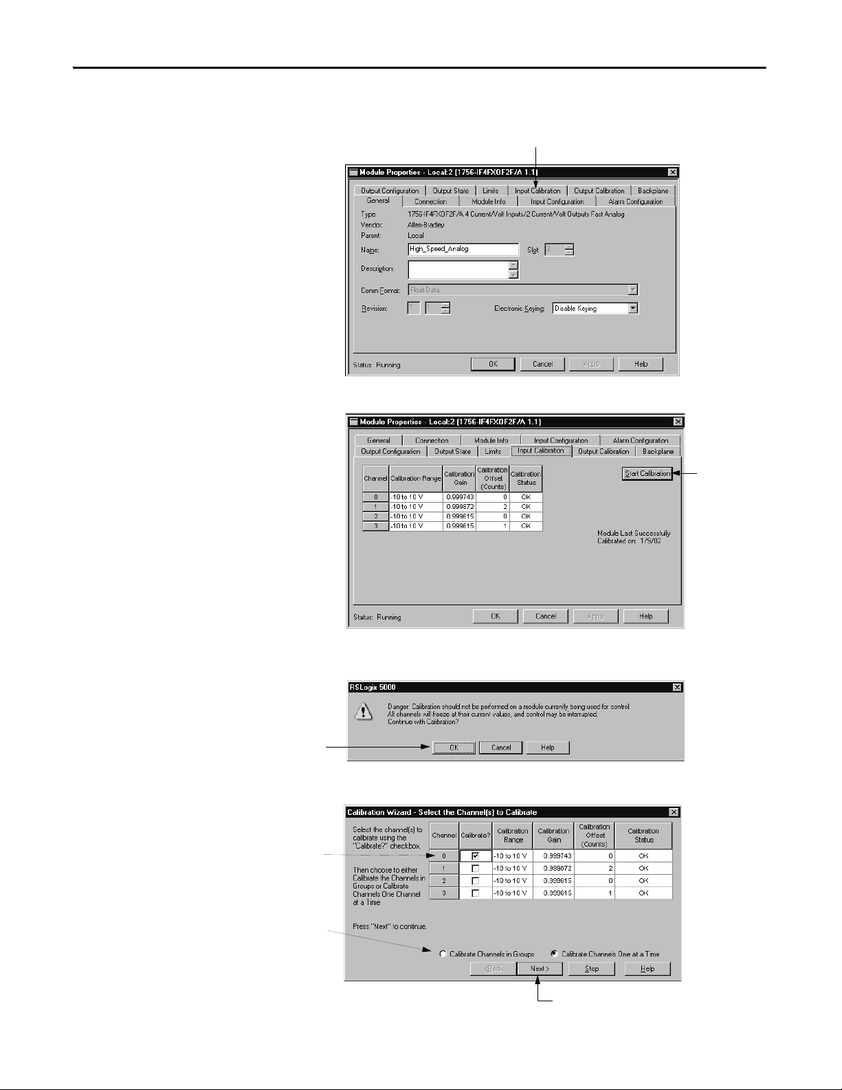
Chapter 6 Calibrate the Module
Click the Input Calibration tab.
Click here to start
calibration.
Click OK to continue calibration.
Choose the channel you
want to calibrate.
Click Next to continue.
Choose whether you want
to calibrate channels in
groups or one at a time.
The Module Properties dialog box appears.
3. On the Input Calibration page, begin calibration.
The software warns you not to calibrate a module currently being used for
control.
4. Set the channels to be calibrated.
88 Rockwell Automation Publication 1756-UM005B-EN-P - January 2013
Page 89
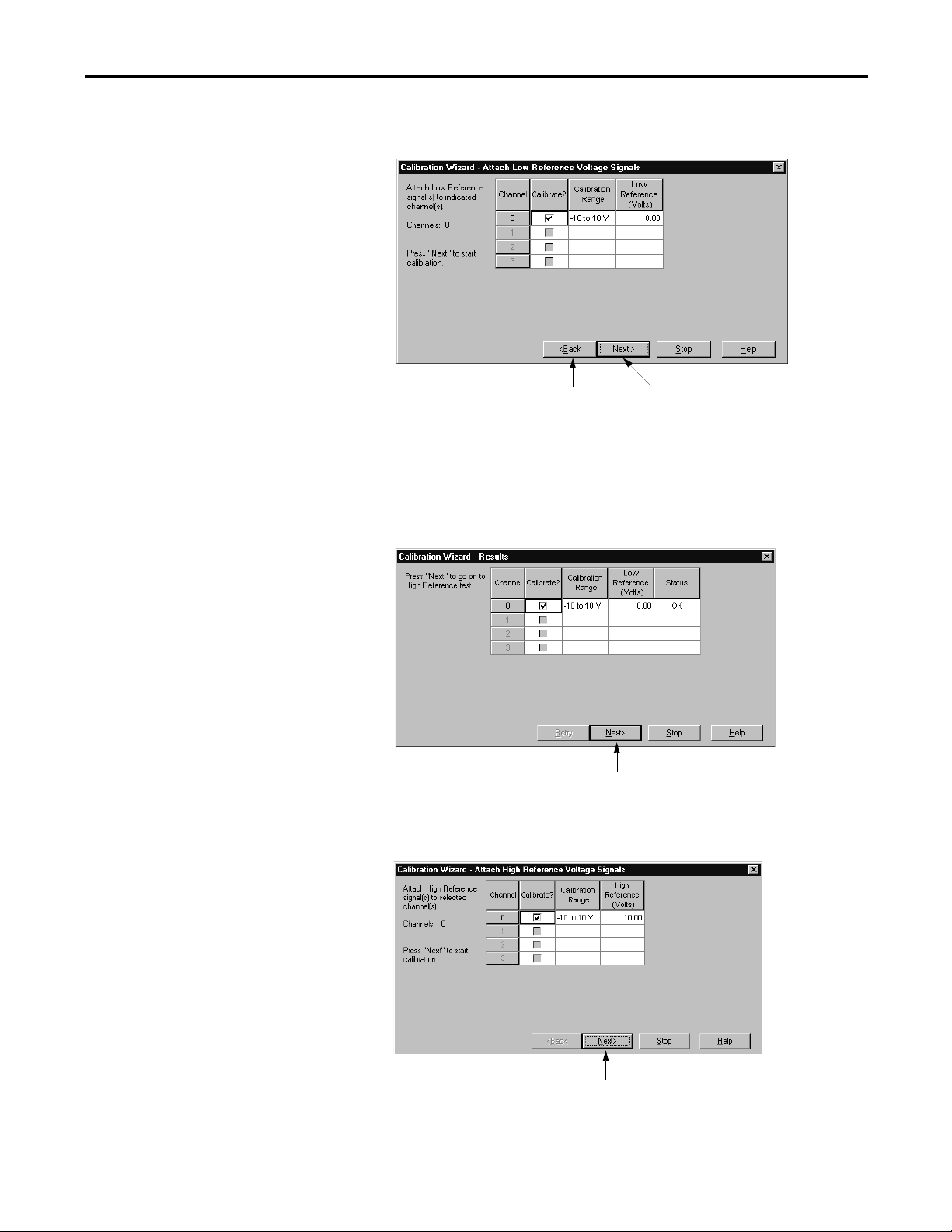
Calibrate the Module Chapter 6
Click Next to calibrate the low
reference.
Click Back to return to the previous
parameters and make any necessary changes.
Click Next to proceed.
Click Next to proceed.
The low reference parameters appear first. These parameters define which
channels will be calibrated for a low reference.
5. Apply the calibrator’s low reference to the module.
The following example shows the channel status after calibrating for a low
reference. If the channels is OK, continue, as shown below. If any channels
report an Error, retry until the status is OK.
The high reference parameters appear next. These parameters define
which channels will be calibrated for a high reference.
Rockwell Automation Publication 1756-UM005B-EN-P - January 2013 89
Page 90

Chapter 6 Calibrate the Module
Click Next to calibrate the high reference.
Click Finish to complete calibration for the channel.
6. Apply the calibrator’s high reference to the module.
The following example shows the channel status after calibrating for a high
reference. If the channels is OK, continue, as shown below. If any channels
report an Error, retry until the status is OK.
The following parameters appear next and define the status of the low and
high calibration.
Calibrate Output Channels
Output calibration requires that you command the output channels to produce
specific voltage or current levels and then measure the signal to verify that the
module is working properly. This process involves these tasks:
• Command the channel (or group of channels) to produce a low reference
signal.
• Verify and record the channel’s output.
• Command the channel (or group of channels) to produce a high reference
signal.
• Verify and record the channel’s output.
90 Rockwell Automation Publication 1756-UM005B-EN-P - January 2013
Page 91
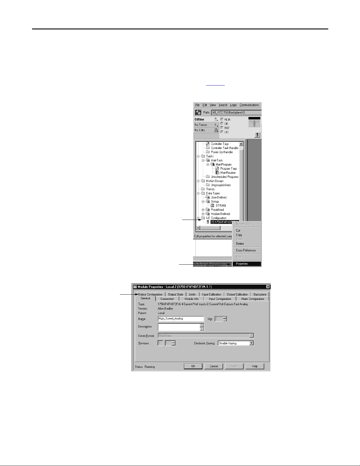
Calibrate the Module Chapter 6
Choose Properties.
Right-click I/O Configuration
to see the menu.
Click the Output Configuration tab.
To calibrate the high-speed analog module’s outputs, follow these steps.
1. Connect your current or voltage meter (depending on what mode your
channel is operating in) to the module. Remember, that you must wire the
module differently for Current mode than for Voltage mode. To see how to
wire for each mode, see page 63
.
2. Access the module’s properties page.
The Module Properties dialog box appears.
Rockwell Automation Publication 1756-UM005B-EN-P - January 2013 91
Page 92

Chapter 6 Calibrate the Module
Choose the channel.
Make sure each channel is using the correct
operating range. If the operating range is
incorrect, use the pull-down menu to change
the range. You must apply any changes to the
module before proceeding.
Click here to begin
calibration.
Select the outputs here.
This example shows Channel 0 using
Voltage mode and Channel 1 using Current
mode. Because the channels use different
modes, the software requires that you
calibrate them separately and disregards
the Calibrate Channels in Groups setting.
Click Next to proceed.
3. Verify the operating range for each channel. You must use the correct
operating range for each channel being calibrated or calibration will not
work. For example, if you want to calibrate channel 0 in Voltage mode, it
must be set for the -10…10V range.
4. Go to the Output Calibration page to begin calibration.
This example shows the calibration range for each channel.
92 Rockwell Automation Publication 1756-UM005B-EN-P - January 2013
5. Select the output channels that you want to calibrate.
Page 93

Calibrate the Module Chapter 6
The software commands the
output channel 0 to produce a low
voltage reference of 0. 00V.
Click Next to proceed.
Click Next to proceed.
6. Command the output channel to produce a low voltage reference level.
7. Record the voltage measurement shown on your voltage calibrator.
We recommend you use a minimum of four digits beyond the decimal
point.
Rockwell Automation Publication 1756-UM005B-EN-P - January 2013 93
Page 94

Chapter 6 Calibrate the Module
Click Next to proceed.
0.0021
The software commands the
output channel 0 to produce a high
voltage reference of 10.00V.
Click Next to proceed.
Record the voltage
measurement.
Click Next to proceed.
If the measurement is within an acceptable range, the channel is marked
with an OK status, such as shown below. If the measurement is not within
an acceptable range, the software returns you to step 6
until the module
produces an acceptable output low reference level.
8. Command the output channel to produce a high voltage reference level.
9. Record the results shown on your voltage calibrator.
94 Rockwell Automation Publication 1756-UM005B-EN-P - January 2013
Page 95

Calibrate the Module Chapter 6
Click Next to continue.
Click Finish to complete the calibration.
If the measurement is within an acceptable range, the channel is marked
with an OK status, such as shown below. If the measurement is not within
an acceptable range, the software returns you to step 8
until the module
produces an acceptable output low reference level.
10. Repeat step 6
through step 9 to calibrate output channel 1 for 0…20 mA
operation.
When you have successfully calibrated both channels, the following
parameters appear.
This completes calibration of input and output channels.
Rockwell Automation Publication 1756-UM005B-EN-P - January 2013 95
Page 96

Chapter 6 Calibrate the Module
Notes:
96 Rockwell Automation Publication 1756-UM005B-EN-P - January 2013
Page 97
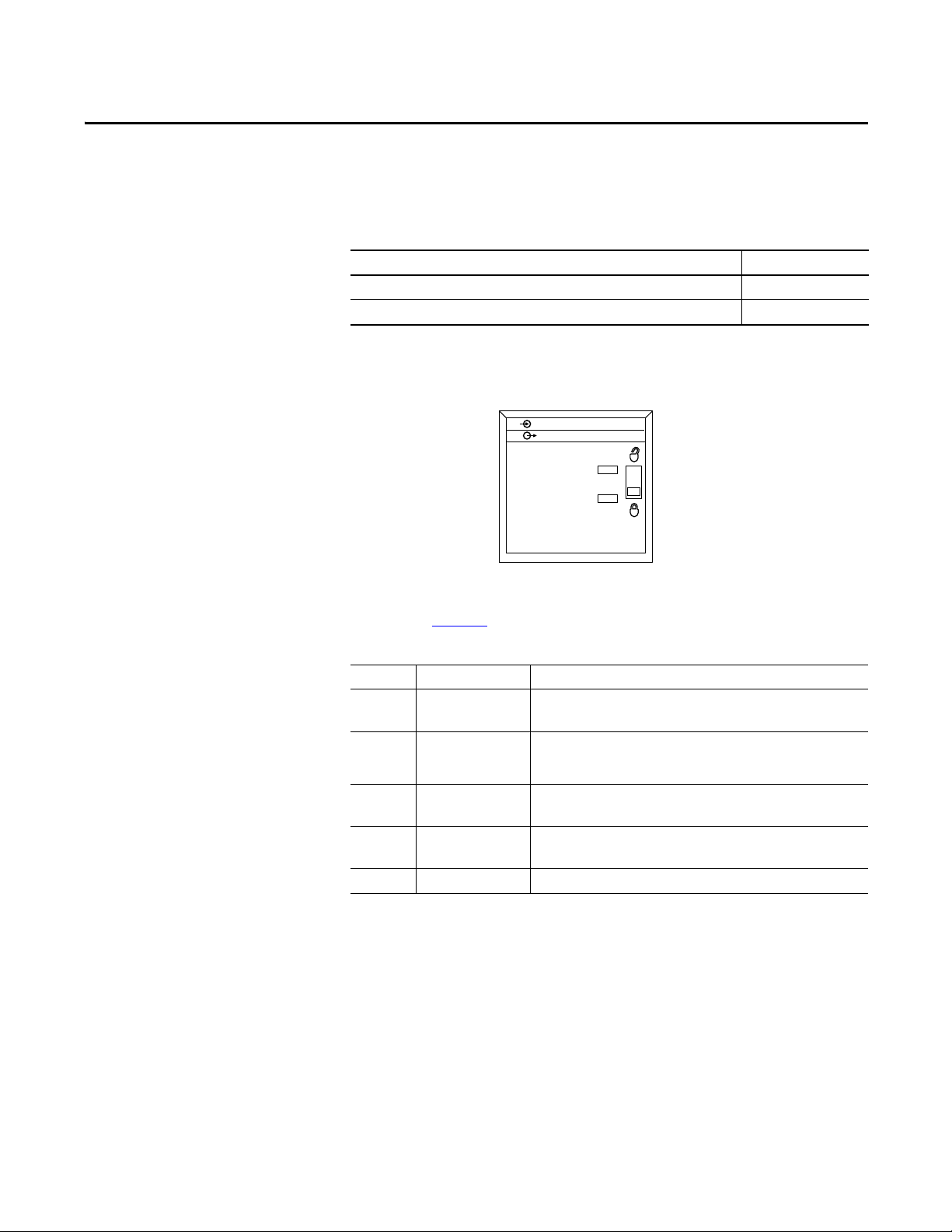
Troubleshoot the Module
ANALOG OUTPUT
CAL
OK
42878
ANALOG INPUT
Top ic P ag e
Use Module Indicators toTroubleshoot 97
Use the Logix Designer Application to Troubleshoot 98
Chapter 7
Use Module Indicators to Troubleshoot
The module uses the status indicators shown below.
Status indicators on the module provide the current status of the module, as
described in Ta b l e 1 3
Table 13 - Status Indicators for Input Modules
Indicator Status Description
OK Steady green The inputs are being multicast and in normal operating state.
OK Flashing green The module has passed internal diagnostics but is not currently performing
OK Flashing red Previously established communication has timed out.
OK Steady red The module must be replaced.
CAL Flashing green The module is in Calibration mode.
.
The outputs are in Run mode.
connected communication or is in Program mode. Inputs are in a normal
operating state. Outputs are in the configured state for Program mode.
Check controller and chassis communication.
Replace the module.
Rockwell Automation Publication 1756-UM005B-EN-P - January 2013 97
Page 98
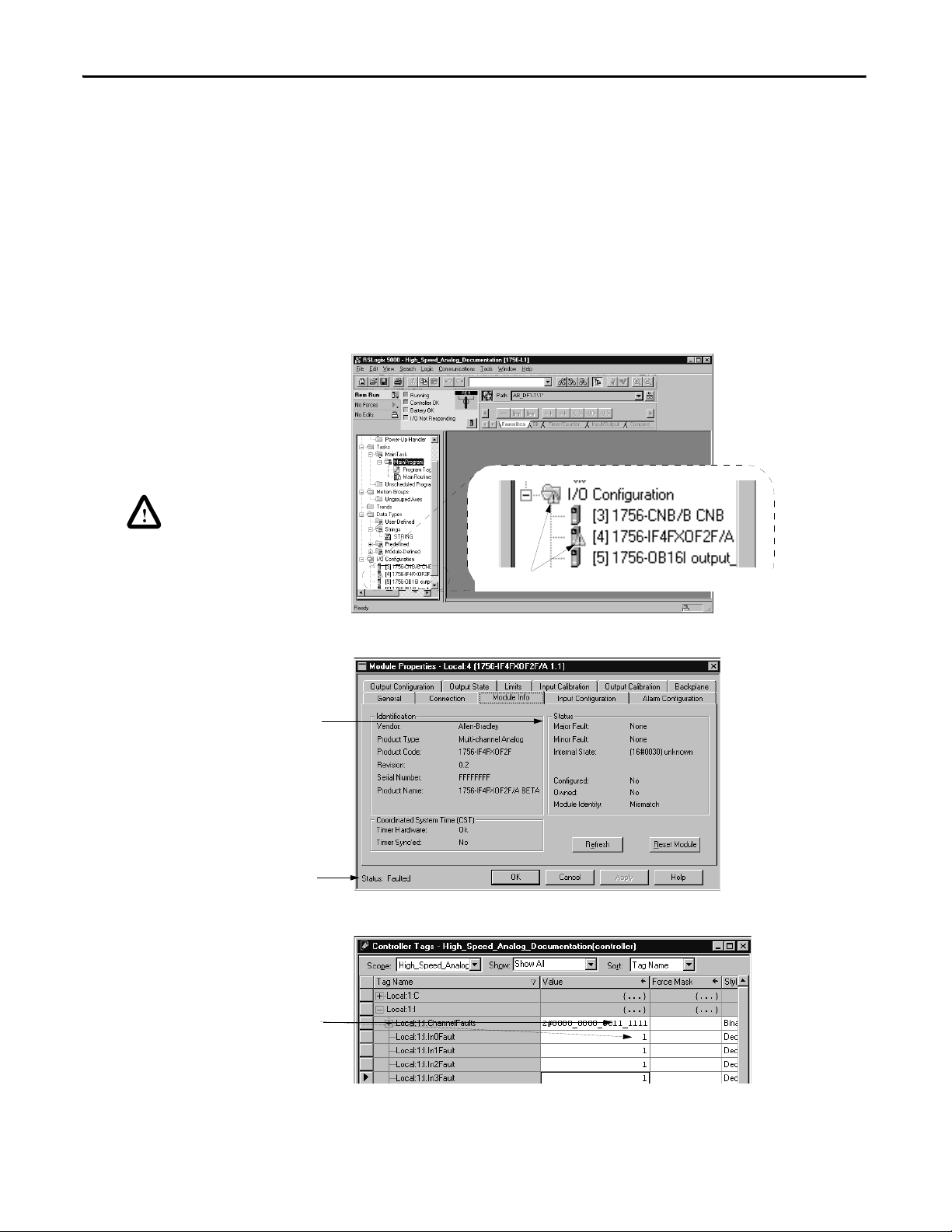
Chapter 7 Troubleshoot the Module
Warning icon when a
communication fault occurs or if the
module is inhibited.
Notification in Tag Editor
A fault has occurred for any point that
lists the number 1 in the Fault line.
Fault Message in Status Line
Warning Signal in I/O Configuraton Tree
Status line provides information on
the connection to the module.
Status section lists major and minor faults
and the internal state of the module.
Warning icon—The module in slot 4 has a communication fault.
Use the Logix Designer Application to Troubleshoot
In addition to the status indicators on the module, the application will alert you
to fault conditions. You will be alerted in one of three ways:
• Warning icon next to the module in the I/O Configuration tree
• Status on the Module Info page
• Fault message in the status line
• Notification in the tag editor
The examples below show fault notification. Diagnostic faults are reported only
in the tag editor.
98 Rockwell Automation Publication 1756-UM005B-EN-P - January 2013
Page 99
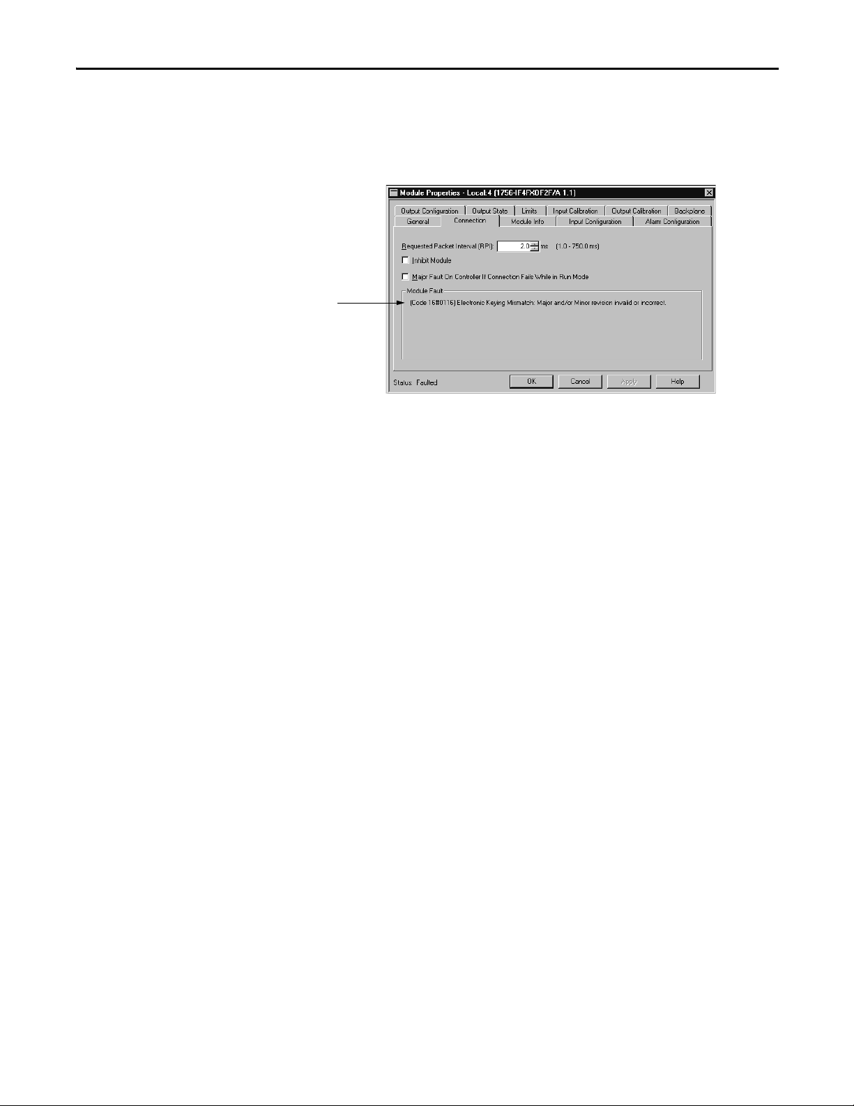
Troubleshoot the Module Chapter 7
The fault t ype is listed here.
Determine the Fault Type
When you are monitoring a module’s configuration properties and receive a
communication fault message, the Connection page lists the type of fault.
For a detailed listing of the possible faults, their causes, and suggested solutions,
see Module Table Faults in the online help.
Rockwell Automation Publication 1756-UM005B-EN-P - January 2013 99
Page 100

Chapter 7 Troubleshoot the Module
Notes:
100 Rockwell Automation Publication 1756-UM005B-EN-P - January 2013
 Loading...