

Rockwell Automation Allen-Bradley ControlLogix B Series, 1756HP-TIME User Manual

User Manual
ControlLogix Time Syncronization Module - Series B
Catalog Number 1756HP-TIME
Allen-Bradley Motors
Important User Information
IMPORTANT
Read this document and the documents listed in the additional resources section about installation, configuration, and
operation of this equipment before you install, configure, operate, or maintain this product. Users are required to
familiarize themselves with installation and wiring instructions in addition to requirements of all applicable codes, laws,
and standards.
Activities including installation, adjustments, putting into service, use, assembly, disassembly, and maintenance are required
t
o be carried out by suitably trained personnel in accordance with applicable code of practice.
If this equipment is used in a manner not specified by the manufacturer, the protection provided by the equipment may be
aired.
imp
In no event will Rockwell Automation, Inc. be responsible or liable for indirect or consequential damages resulting from the
or application of this equipment.
use
The examples and diagrams in this manual are included solely f
or illustrative purposes. Because of the many variables and
requirements associated with any particular installation, Rockwell Automation, Inc. cannot assume responsibility or
liability for actual use based on the examples and diagrams.
No patent liability is assumed by Rockwell Automation, Inc. with respect to use of information, circuits, equipment, or
tware described in this manual.
sof
Reproduction of the contents of this manual, in whole or in part, without written permission of Rockwell Automation,
nc., is prohibited.
I
Throughout this manual, when necessary, we use notes to make you aware of safety considerations.
WARNING: Identifies information about practices or circumstances that can cause an explosion in a hazardous environment,
which may lead to personal injury or death, property damage, or economic loss.
ATTENTION: Identifies information about practices or circumstances that can lead to personal injury or death, property
damage, or economic loss. Attentions help you identify a hazard, avoid a hazard, and recognize the consequence.
Identifies information that is critical for successful application and understanding of the product.
Labels may also be on or inside the equipment to provide specific precautions.
SHOCK HAZARD: Labels may be on or inside the equipment, for example, a drive or motor, to alert people that dangerous
voltage may be present.
BURN HAZARD: Labels may be on or inside the equipment, for example, a drive or motor, to alert people that surfaces may
reach dangerous temperatures.
ARC FLASH HAZARD: Labels may be on or inside the equipment, for example, a motor control center, to alert people to
potential Arc Flash. Arc Flash will cause severe injury or death. Wear proper Personal Protective Equipment (PPE). Follow ALL
Regulatory requirements for safe work practices and for Personal Protective Equipment (PPE).
Allen-Bradley, ControlFLASH, ControlLogix, Logix5000, R SLogix, Studio 5000 Automation Engineering & Design Environment, Studio 5000, Studio 5000 Logix Designer, Rockwell S oftware, and Rockwell Automation
are trademarks of Rockwell Automation, Inc.
Trademarks not belonging to Rockwell Automation are property of their respective companies.

Table of Contents
Preface
Installation
Setup
Operation
Studio 5000 Environment . . . . . . . . . . . . . . . . . . . . . . . . . . . . . . . . . . . . . . . . . . 5
1756HP-TIME Module Overview . . . . . . . . . . . . . . . . . . . . . . . . . . . . . . . . . . 5
Additional Resources . . . . . . . . . . . . . . . . . . . . . . . . . . . . . . . . . . . . . . . . . . . . . . .
6
Chapter 1
Hardware . . . . . . . . . . . . . . . . . . . . . . . . . . . . . . . . . . . . . . . . . . . . . . . . . . . . . . . . . 7
GPS Antenna . . . . . . . . . . . . . . . . . . . . . . . . . . . . . . . . . . . . . . . . . . . . . . . . . . . . . . 8
Software. . . . . . . . . . . . . . . . . . . . . . . . . . . . . . . . . . . . . . . . . . . . . . . . . . . . . . . . . . . 8
Chapter 2
BOOTP. . . . . . . . . . . . . . . . . . . . . . . . . . . . . . . . . . . . . . . . . . . . . . . . . . . . . . . . . . . 9
Factory Defaults . . . . . . . . . . . . . . . . . . . . . . . . . . . . . . . . . . . . . . . . . . . . . . . . . . . 9
ControlFLASH Software . . . . . . . . . . . . . . . . . . . . . . . . . . . . . . . . . . . . . . . . . 10
The Logix Designer Application Configuration. . . . . . . . . . . . . . . . . . . . . 10
View the Satellite Status in the Logix Designer Application . . . . . . . . . . 12
Satellite Signal . . . . . . . . . . . . . . . . . . . . . . . . . . . . . . . . . . . . . . . . . . . . . . . 12
Satellite Position . . . . . . . . . . . . . . . . . . . . . . . . . . . . . . . . . . . . . . . . . . . . . 13
1756HP-TIME Module AOP Configuration Parameters. . . . . . . . . . . . 13
Chapter 3
Logix5000 Controller Input Image . . . . . . . . . . . . . . . . . . . . . . . . . . . . . . . . 17
Logix5000 Controller Output Image . . . . . . . . . . . . . . . . . . . . . . . . . . . . . . 20
Web Interface . . . . . . . . . . . . . . . . . . . . . . . . . . . . . . . . . . . . . . . . . . . . . . . . . . . 21
Time Synchronization
Specifications
Chapter 4
1588 Precision Time Protocol (CIP Sync). . . . . . . . . . . . . . . . . . . . . . . . . . 23
1756HP-TIME Module as a PTP Master. . . . . . . . . . . . . . . . . . . . . . . 23
Configure the Ethernet Module/Controller PTP/CIP
Sync Settings. . . . . . . . . . . . . . . . . . . . . . . . . . . . . . . . . . . . . . . . . . . . . . . . .
PTP as a Time Source. . . . . . . . . . . . . . . . . . . . . . . . . . . . . . . . . . . . . . . . . 26
Network Time Protocol (NTP) . . . . . . . . . . . . . . . . . . . . . . . . . . . . . . . . . . .
1756HP-TIME Module as an NTP Server. . . . . . . . . . . . . . . . . . . . . .
1756HP-TIME Module as an NTP Client . . . . . . . . . . . . . . . . . . . . . 28
IRIG-B. . . . . . . . . . . . . . . . . . . . . . . . . . . . . . . . . . . . . . . . . . . . . . . . . . . . . . . . . .
1756HP-TIME Module as an IRIG-B Master
1756HP-TIME Module as an IRIG-B Slave . . . . . . . . . . . . . . . . . . . . 30
CST and UTC Time Conversion . . . . . . . . . . . . . . . . . . . . . . . . . . . . . . . . .
. . . . . . . . . . . . . . . . . . 29
24
26
26
29
30
Appendix A
Technical Specifications . . . . . . . . . . . . . . . . . . . . . . . . . . . . . . . . . . . . . . . . . . 31
Cable Specifications . . . . . . . . . . . . . . . . . . . . . . . . . . . . . . . . . . . . . . . . . . . . . .
GPS Antenna Specifications . . . . . . . . . . . . . . . . . . . . . . . . . . . . . . . . . . . . . . 32
Dimensions. . . . . . . . . . . . . . . . . . . . . . . . . . . . . . . . . . . . . . . . . . . . . . . . . . . . . .
31
33
Allen-Bradley Motors
Rockwell Automation Publication 1756-UM542A-EN-P - September 2014 3

Table of Contents
Appendix B
1756HP-TIME Module Status
CST/UTC Conversion Message Blocks
Operating Modes
GPS Antenna Cable Extensions
Status Indicators . . . . . . . . . . . . . . . . . . . . . . . . . . . . . . . . . . . . . . . . . . . . . . . . . 35
Status Messages . . . . . . . . . . . . . . . . . . . . . . . . . . . . . . . . . . . . . . . . . . . . . . . . . .
36
Appendix C
CST to UTC and Gregorian Time Conversion . . . . . . . . . . . . . . . . . . . . . 37
UTC to Gregorian Time Conversion . . . . . . . . . . . . . . . . . . . . . . . . . . . . . . 37
Satellite Information. . . . . . . . . . . . . . . . . . . . . . . . . . . . . . . . . . . . . . . . . . . . . . 38
Appendix D
GPS Source . . . . . . . . . . . . . . . . . . . . . . . . . . . . . . . . . . . . . . . . . . . . . . . . . . . . . . 39
IRIG-B Source . . . . . . . . . . . . . . . . . . . . . . . . . . . . . . . . . . . . . . . . . . . . . . . . . . . 40
PTP Source . . . . . . . . . . . . . . . . . . . . . . . . . . . . . . . . . . . . . . . . . . . . . . . . . . . . . . 40
NTP Source . . . . . . . . . . . . . . . . . . . . . . . . . . . . . . . . . . . . . . . . . . . . . . . . . . . . . 41
Appendix E
Cable Extensions . . . . . . . . . . . . . . . . . . . . . . . . . . . . . . . . . . . . . . . . . . . . . . . . . 43
Determine the Length of the Cable. . . . . . . . . . . . . . . . . . . . . . . . . . . . . 43
Determine the Attenuation Rate of the Cable . . . . . . . . . . . . . . . . . . . 43
Example – Determining Cable Requirements . . . . . . . . . . . . . . . . . . . 44
Cable Extension Kits. . . . . . . . . . . . . . . . . . . . . . . . . . . . . . . . . . . . . . . . . . 44
Lightning Protection Devices. . . . . . . . . . . . . . . . . . . . . . . . . . . . . . . . . . . . . . 45
Glossary
Index
. . . . . . . . . . . . . . . . . . . . . . . . . . . . . . . . . . . . . . . . . . . . . . . . . . . . . . . . . . . . . . . . . 47
. . . . . . . . . . . . . . . . . . . . . . . . . . . . . . . . . . . . . . . . . . . . . . . . . . . . . . . . . . . . . . . . . 49
4 Rockwell Automation Publication 1756-UM542A-EN-P - September 2014

Top ic Page
Studio 5000 Environment 5
1756HP-TIME Module Overview 5
Additional Resources 6
Preface
Studio 5000 Environment
The Studio 5000 Automation Engineering & Design Environment™ combines
engineering and design elements into a common environment. The first element
is the Studio 5000 Logix Designer™ application. The Logix Designer application
is the rebranding of RSLogix™ 5000 software and will continue to be the product
to program Logix5000™ controllers for discrete, process, batch, motion, safety,
and drive-based solutions.
The Studio 5000® environment is the foundation for the future of Rockwell
A
utomation® engineering design tools and capabilities. The Studio 5000
environment is the one place for design engineers to develop all of the elements of
their control system.
1756HP-TIME Module Overview
Allen-Bradley Motors
This user manual describes the functionality, installation, configuration, and
operation of the 1756HP-TIME module, series B, firmware revision 3.001.
The 1756HP-TIME module provides accurate time synchronization on different
terfaces by using Global Positioning System (GPS) technology. The
in
1756HP-TIME module can obtain time from various sources, and provide time
synchronization on other devices by acting as a gateway between different time
synchronization methods and standards.
Rockwell Automation Publication 1756-UM542A-EN-P - September 2014 5

Preface
Time synchronization is accomplished by using these methods, standards, and
protocols:
• The
ControlLogix® backplane for Coordinated System Time (CST) and
Coordinated Universal Time (UTC) conversion.
• Inter-range Instrumentation Group, code B (IRIG-B) standards.
• Precision Time Protocol (PTP) on Ethernet and the ControlLogix
backplane.
• Network Time Protocol (NTP) on Ethernet.
The 1756HP-TIME module provides GPS position in the form of latitude,
gitude, and altitude (LLA).
lon
The 1756HP-TIME module provides course and route information in the form
round speed (knots) with heading in the form of degrees from true north.
of g
Additional Resources
These documents contain additional information concerning related products
from Rockwell Automation.
Resource Description
Integrated Architecture and CIP Sync Configuration
Application Technique, publication IA-AT003
ControlLogix System User Manual, publication 1756-UM001 Describes the necessary tasks to install, configure,
EtherNet/IP Network Configuration User Manual,
publication
ControlFLASH® Firmware Upgrade Software User Manua l,
publication 1756-UM105
Industrial Automation Wiring and Grounding Guidelines,
publication 1770-4.1
Product Certifications website,
ENET-UM001
http://www.ab.com Provides declarations of conformity, certificates, and
This document explains CIP sync technology and how
you can synchronize clocks within the Rockwell
Automation Integrated Architecture.
program, and operate a ControlLogix system.
Provides Bootstrap Protocol/ Dynamic Host
Configuration Protocol (BOOTP/DHCP) information for
setting the IP address of the module.
Describes the necessary tasks to install, and use the
ControlFLASH software to update the module firmware.
Provides general guidelines for installing a Rockwell
Automation industrial system.
other certification details.
You can view or download publications at
http:/www.rockwellautomation.com/literature/. To order paper copies of
technical documentation, contact your local Allen-Bradley distributor or
R
ockwell Automation sales representative.
6 Rockwell Automation Publication 1756-UM542A-EN-P - September 2014
Installation
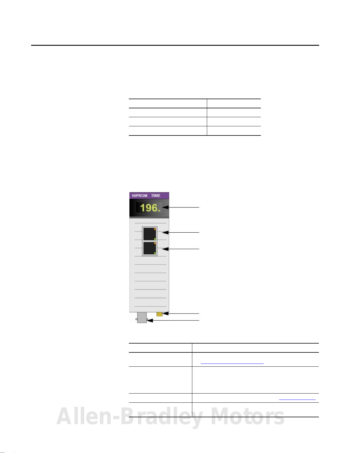
Status Indicators and Messages
Ethernet Connection 1
Ethernet Connection 2
GPS Subminiture Version A (SMA) Connector
IRIG-B Coaxial Connector
Top ic Page
Hardware 7
GPS Antenna 8
Software 8
Chapter 1
Hardware
The 1756HP-TIME module operates within the ControlLogix platform. All
power required for the operation of the module is supplied by the ControlLogix
backplane.
Figure 1 - 1756HP-TIME Module, Front View
Table 1 - 1756HP-TIME Module Hardware Descriptions
Hardware Description
Status indicators and messages Provides status and operational information for the 1756HP-TIME module.
Ethernet connector 1 and
Ethernet connector 2
(uses Rockwell Automation®
dual-port switch technology)
GPS SMA connector Connect the GPS b ullet antenna to this connector. See GPS Antenna on page 8.
IRIG-B coaxial connec tor Connect the IRIG-B network cable to this connector. The 1756HP-TIME module
See 1756HP-TIME Module Status on page 35.
PTP and NTP time synchronization uses the Ethernet connections.
Note: This connection is not a bridge to the backplane and cannot be used to
view m
odules on the backplane.
can be configured as a master clock or a slave clock on the IRIG-B network.
Allen-Bradley Motors
Rockwell Automation Publication 1756-UM542A-EN-P - September 2014 7
Chapter 1 Installation
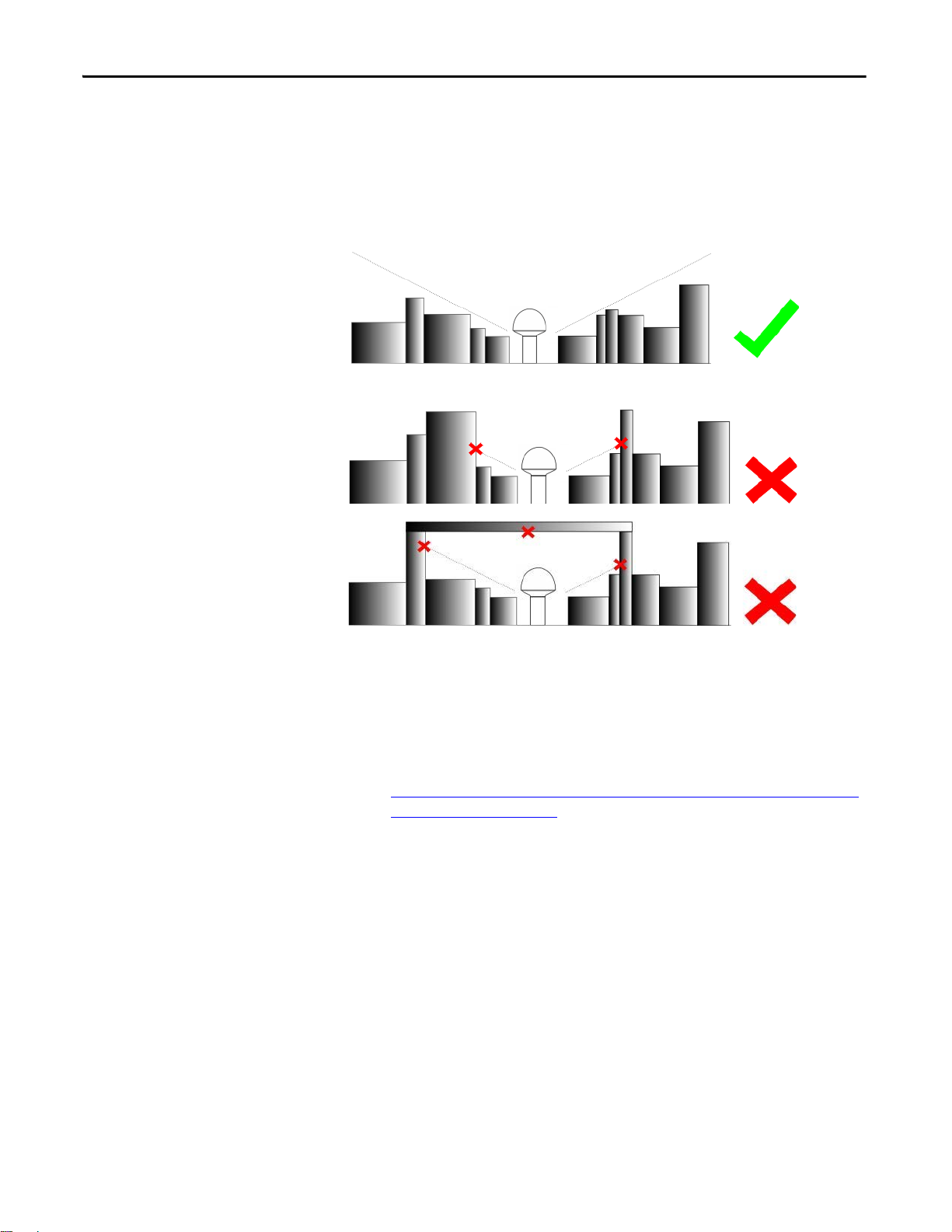
GPS Antenna
Install the GPS antenna with a clear view of the sky (do not install the antenna
where objects can obstruct the view of the antenna to the sky). If an antenna is
installed with a limited view of the sky, the GPS receiver can have a low satellite
lock count, or be unable to obtain a lock. A limited view of the sky can cause
inaccurate time synchronization.
Figure 2 - GPS Antenna Installation with Clear View of the Sky
Figure 3 - GPS Antenna Installation with Obstructed View of the Sky
Software
Use this software to configure and operate the 1756HP-TIME module:
• The Studio 5000 Logix Designer application
• The Add-on Profile (AOP) for the 1756HP-TIME module, available for
download at this link:
http://www.hiprom.com/Pages/Products/1756_CLX/1756HP-TIME/
web/1756HP-TIME.htm
8 Rockwell Automation Publication 1756-UM542A-EN-P - September 2014

Setup
Top ic Page
BOOTP 9
Fac tory Defaul ts 9
ControlFLASH Software 10
The Logix Designer Application Configuration 10
View the Satellite Status in the Logix Designer Application 12
1756HP-TIME Module AOP Configuration Parameters 13
Chapter 2
BOOTP
Factory Defaults
Use BOOTP to set the initial IP address for the 1756HP-TIME module. The
module comes from the factory with BOOTP enabled.
The BOOTP/DHCP server is a standalone server that you can use to set an IP
s.
addres
Access the BOOTP/DHCP server from one of these locations:
rograms > Rockwell Software > BOOTP-DHCP Server
• P
• Tools directory on the Studio 5000 environment installation CD
If you have not installed the BOOTP/DHCP server, you can download and
ll it from
insta
To set the IP address of the module with a BOOTP/DHCP server, follow the
ps found in EtherNet/IP Network Configuration User Manual, publication
ste
ENET-UM001.
If the module fails or becomes inoperable, the module reboots with
factory-loaded boot software. The display informs you of the error and suggests a
method to fix the error. If there is a firmware error, use the ControlFLASH
software to restore the module to a working condition.
http://www.ab.com/linked/networks/ethernet/bootp.html.
Allen-Bradley Motors
Rockwell Automation Publication 1756-UM542A-EN-P - September 2014 9
Chapter 2 Setup
IMPORTANT
IMPORTANT
ControlFLASH Software
The Logix Designer Application Configuration
Use the ControlFLASH software to upgrade the software to a newer version.
For more information on the ControlFLASH software and how to use it, see
C
ontrolFLASH Firmware Upgrade Software User Manual, publication
UM105.
The latest firmware can be found at this link:
Products/1756_CLX/1756HP-TIME/web/1756HP-TIME.htm.
Before you can program the 1756HP-TIME module, the AOP for the module
must be installed. You also need admin rights for the module to view and
configure the AOP.
The installer for the AOP can be found at this link:
http://www.hiprom.com/Pages/Products/1756_CLX/1756HP-TIME/web/
1756HP-TIME.htm.
Each 1756HP-TIME module is programmed to work with a single Logix5000
controller.
http://www.hiprom.com/Pages/
1756-
There is no direct communication between the 1756HP-TIME module Ethernet
ports and a Logix5000 controller. If the 1756HP-TIME module resides in a
remote Logix rack, it needs to communicate through an EN2T(R) module in the
same rack.
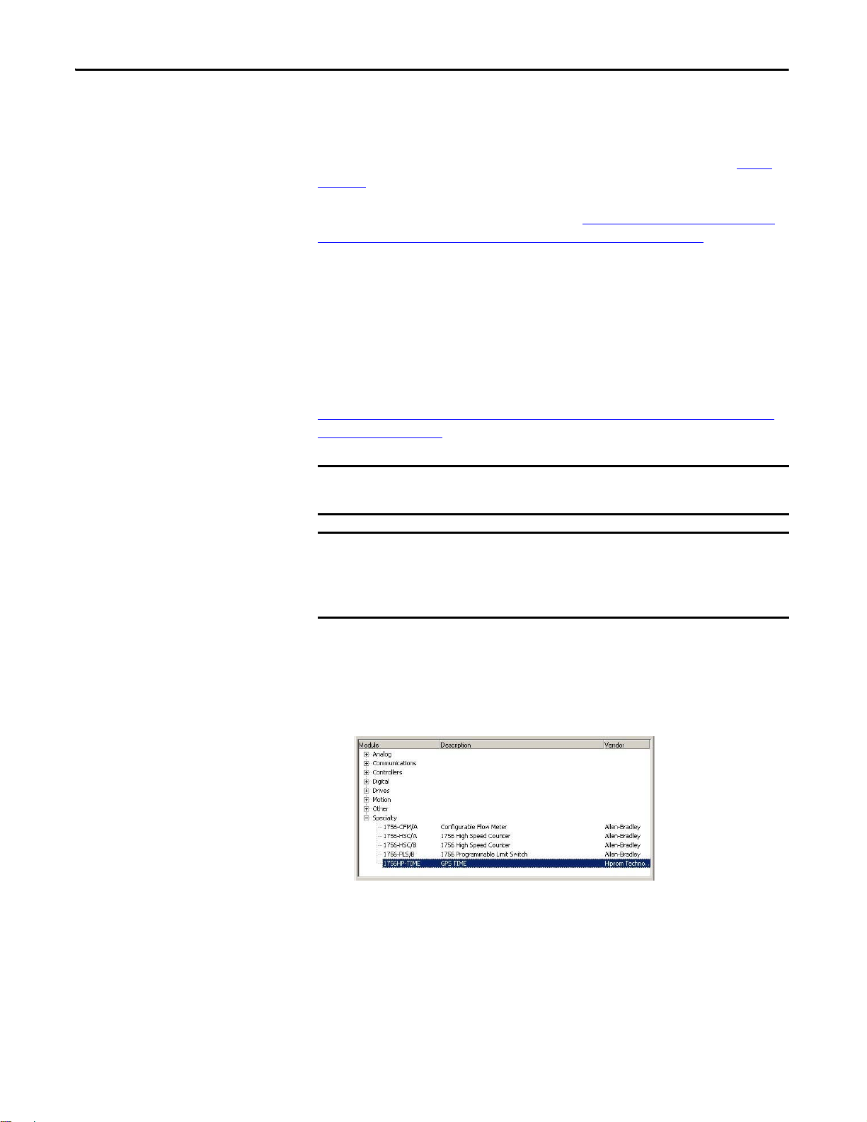
Follow these steps to configure the 1756HP-TIME module in the Logix
Designer application.
1. Doub
le-click the 1756HP-TIME module in the I/O tree in the Logix
Designer application.
The New Module dialog box appears.
10 Rockwell Automation Publication 1756-UM542A-EN-P - September 2014
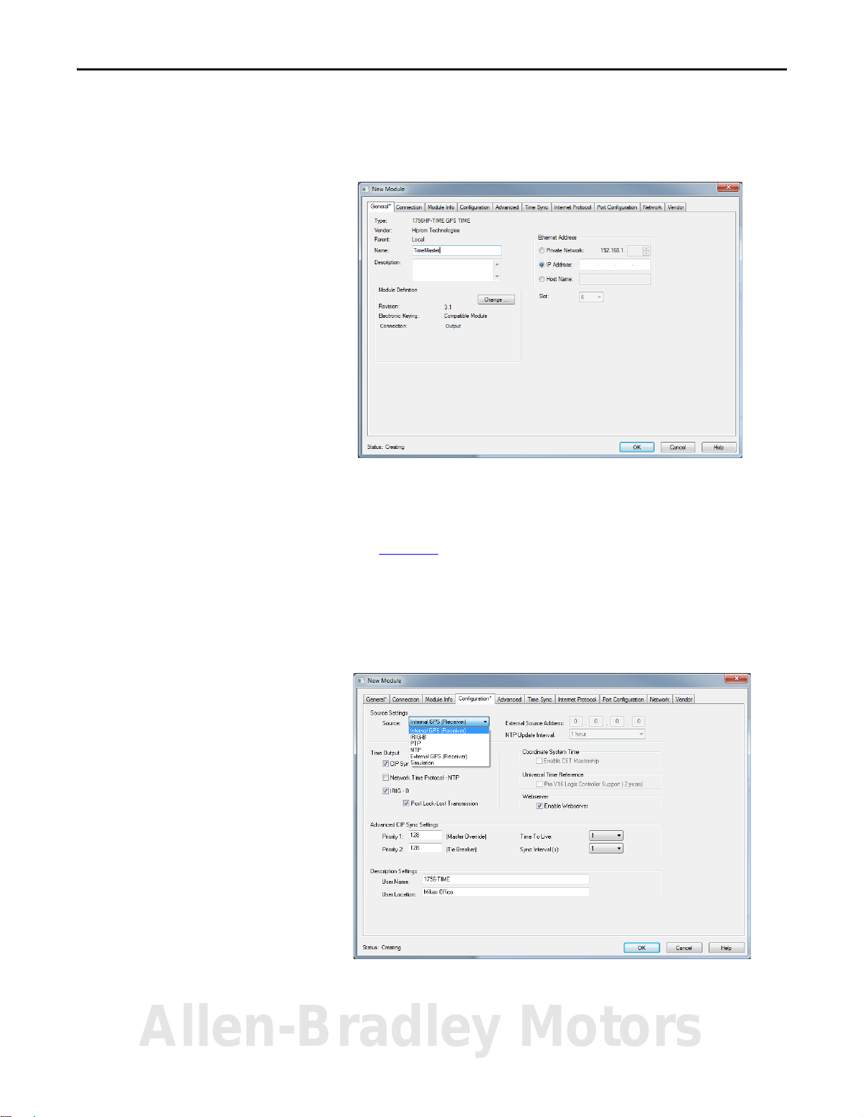
2. Enter a name for the module.
3. Enter a brief description for the module.
4. Enter the IP address for the module.
Setup Chapter 2
5. Click the Configuration tab.
6. From the Source Settings pull-down menu, choose the time source that
you want to use.
See Chapter 4
7. Select the Time Output format.
8. Enter the Advanced CIP Sync Settings.
9. Enter the Description Settings.
10. Click OK.
for more information on the source types.
The time properties of the 1756HP-TIME module are now configured.
Allen-Bradley Motors
Rockwell Automation Publication 1756-UM542A-EN-P - September 2014 11
Chapter 2 Setup
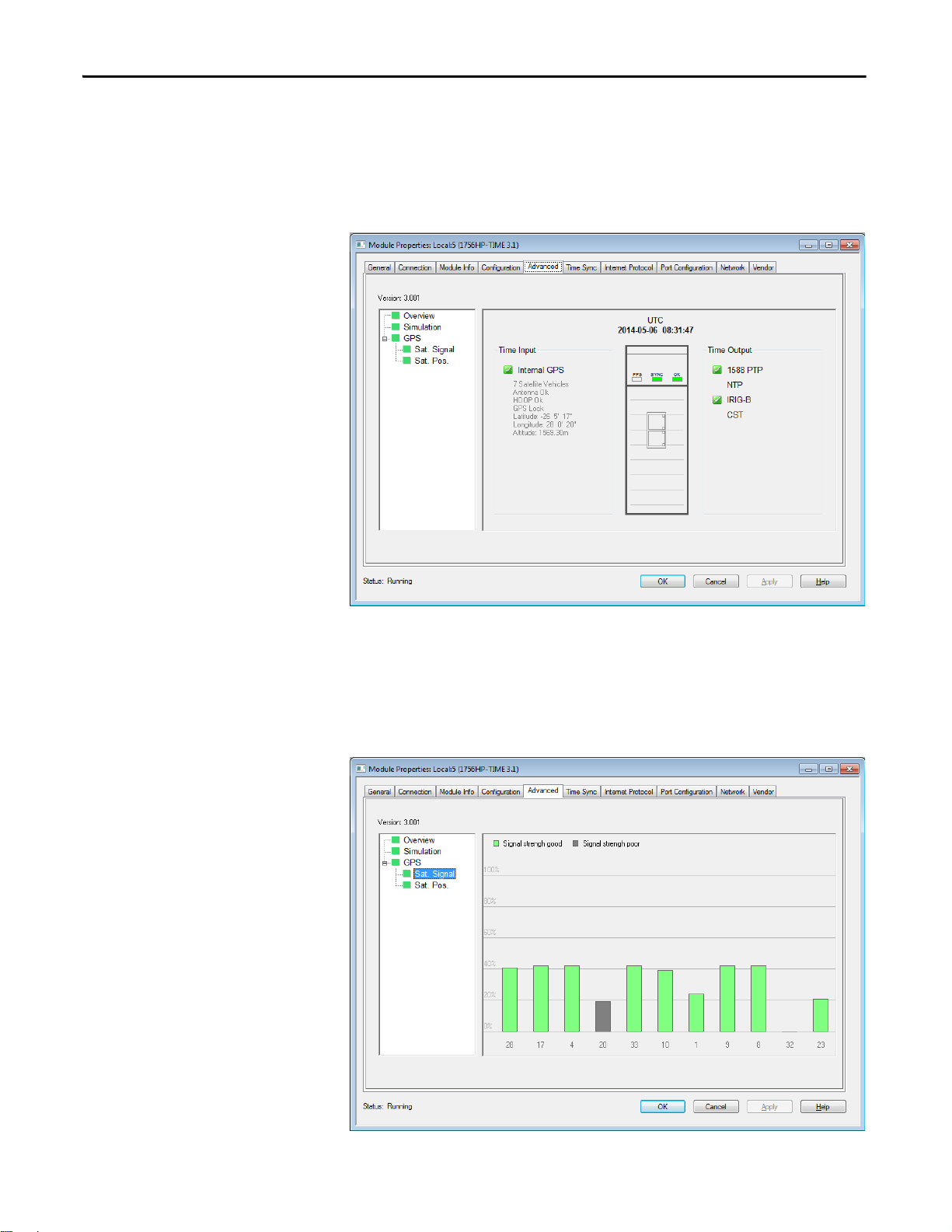
View the Satellite Status in the Logix Designer Application
Click the Advanced tab to view the source of the time (Time Input), and see if
the time source is valid and available (green) or invalid (red). You can also view
the output type (Time Output), the UTC time of the 1756HP-TIME module,
and the GPS coordinates of the satellite (when a connection is locked).
Figure 4 - 1756HP-TIME Module Properties Dialogue Box, Advanced Tab
Satellite Signal
Click Sat. Signal to view the signal strength of the satellites.
Figure 5 - 1756HP-TIME Module Properties Dialogue Box, Sat. Signal Node
12 Rockwell Automation Publication 1756-UM542A-EN-P - September 2014
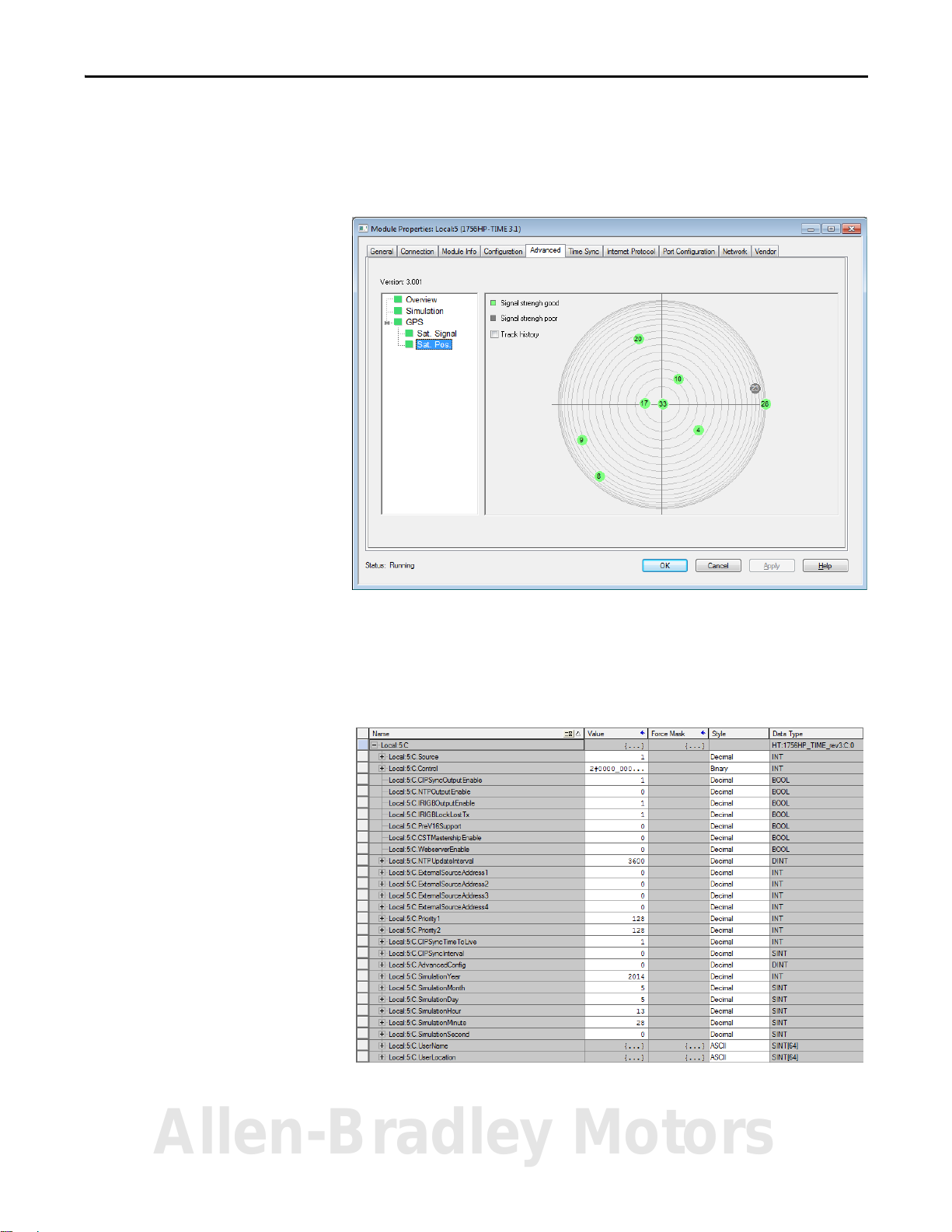
Satellite Position
Click Sat. Pos. to view the position of the satellites in the sky.
Figure 6 - 1756HP-TIME Module Properties Dialogue Box, Sat. Pos. Node
Setup Chapter 2
1756HP-TIME Module AOP Configuration Parameters
This section describes the AOP configuration parameters for the 1756HP-TIME
module. This section is for information purposes. The AOP is used to configure
all the relevant module parameters.
Allen-Bradley Motors
Rockwell Automation Publication 1756-UM542A-EN-P - September 2014 13

Chapter 2 Setup
Table 2 - AOP Configuration Parameters
Parameter Description Value
Source Indicates the time source that is used for the module. 1 = GPS
2 = IRIG-B
3 = PTP
4 = NTP
5 = External GPS (future)
6 = Simulation
CIPSyncOutputEnable When this bit is set, the module enables 1588 PTP (CIP sync) output. 0 = 1588 PTP (CIP sync) output is disabled
1 = 1588 PTP (CIP sync) output is enabled
NTPOutputEnable When this bit is set, the module enables NTP on Ethernet. 0 = NTP v3 RF(1305) output is disabled
1 = NTP v3 RF(1305) output is enabled
IRIGBOutputEnable When this bit is set, the module enables IRIG-B on the coaxial interface. 0 = IRIG-B-122 output is disabled
1 = IRIG-B-122 output is enabled
IRIGBLockLostTX When this bit is set, the module keeps sending an IRIG-B signal aft
PreV16Support If you are using RSLogix 5000 software, version 16.00.00 and later, or the Studio 5000
CSTMastershipEnable Indicates if the module is the CST master clock on the local rack (if no other CST master
WebserverEnable Allows you to access the web server from a web browser pointed to the IP address of the
NTPUpdateInterval The time (in seconds) when the module requests an update of the time from the NTP
ExternalSo urceAddress The external source address is used for one of two sources depending on how the
Priority1 This is the override for the Best Master Clock Algorithm (BMCA). The default is 128.
Priority2 This is used to break a tie between two modules with the same priority 1 value. The default is 128.
CIPSyncTimeToLive Limits the lifespan of data in a network. It
CIPSyncInterval The time interval when the module sends out a PTP sync packet. Allowed values:
AdvancedConfig These are various bits used to set c
time source.
If this bit is clear, the module stops sending a valid IRIG-B signal when it has lost lock
with the time source, as long as it has had lock at least once previously.
environment, version 21.00.00 and later, the UTC time base is different than earlier
versions of RSLogix 5000 software.
The setting syncs the time between Logix5000 controllers that use any version of
RSLogix 5000 software or the Studio 5000 environment.
clocks are currently active).
module.
server.
guration is set:
confi
• If the time source is set to NTP, this is the IP address of the source that is used.
• If the source is set to External GPS, this is the IP address of the GPS receiver.
indefinitely.
prevents the IP packet from circulating
ertain options in the module. Bit:
er it has lost lo ck to th e
0 = Module stops sending IRIG-B when lock is lost
1 = Module continues sending IRIG-B, even when a lock is
lost
0 = For all versions of RSLogix 5000 software or the Studio
5000 environment
1 = For RSLogix 5000 software, version 16.00.00 and earlier.
0 = Module does not attempt to be the CST master clock
1 = Module does attempt to be the CST master clock
0 = Module does not allow access to the web server
1 = Module allows access to the web server
Example:
5 = 5 seconds
30 = 30 seconds
300 = 5 minutes
3600 = 1 hour
86400 = 1 day
604800 = 1 week
In this example, the module uses external IP address:
192.168.1.100
Byte 0 = 192
Byte 1 = 168
Byte 2 = 1
Byte 3 = 100
Values lower than 128 indicate preference on the network.
Values lower than 128 indicate preference on the network.
Example:
1 = the packet circulates once
1/2 = 500 ms
1 = 1 second
2 = 2 seconds
0 =Simulation Mode
1…31 = Reserved
14 Rockwell Automation Publication 1756-UM542A-EN-P - September 2014

Table 2 - AOP Configuration Parameters (Continued)
Parameter Description Value
SimulationYear When the module is in simulation mode, use this to set the initial year to be used by the
SimulationMonth When the module is in simulation mode, use this to set the initial month to be used by
SimulationDay When the module is in simulation mode, use this to set the initial day to be used by the
SimulationHour When the module is in simulation mode, use this to set the initial hour to be used by the
SimulationMinute When the module is in simulation mode, use this to set the initial minute to be used by
SimulationSecond When the module is in simulation mode, use this to set the initial second to be used by
UserName Use this parameter to identify the time module, visible in CIP sync synchronization. Example:
UserLocation Use this parameter to provide extra information to identify the location of the module. Example:
module.
the module.
.
module
module.
the module.
the module
.
Example:
29 April 2014
Year = 2014
Example:
29 April 2014
Month = 4
Example:
29 April 2014
Day = 29
Example:
11:14:23 AM
Hour =11
Example:
11:14:23 AM
Minute =14
Example:
11:14:23 AM
Second =23
1756HP-TIME
Basement
Setup Chapter 2
Allen-Bradley Motors
Rockwell Automation Publication 1756-UM542A-EN-P - September 2014 15

Chapter 2 Setup
Notes:
16 Rockwell Automation Publication 1756-UM542A-EN-P - September 2014
 Loading...