

Page 1

Installation Instructions
EtherNet/IP Web Server Module
Catalog Number 1756-EWEB
Use this manual as a guide to install the EtherNet/IP® Web Ser v e r M o d u l e.
Note that this document covers hardware installation and some configuration
procedures to get you started. Refer to the EtherNet/IP Web Server Module User
Manual, publication number ENET-UM527, for more detailed configuration
information.
The following table lists the contents of this document and where to find
specific information.
Topic See Page
Important User Information 2
Environment and Enclosure 2
Preventing Electrostatic Discharge 4
European Hazardous Location Approval 4
North American Hazardous Location Approval 5
Identify Module Components 8
Prepare the Chassis for Module Installation 9
Determine Module Slot Location 10
Install the Module 11
Using the Web Server Module 19
Troubleshooting the Module 25
Where to Find More Information on Configuring the Module 26
Specifications 27
Rockwell Automation Support 30
Publication 1756-IN588A-EN-P - February 2004
Page 2
2 EtherNet/IP Web Server Module
Important User Information
Solid state equipment has operational characteristics differing from those of
electromechanical equipment. Safety Guidelines for the Application, Installation and
Maintenance of Solid State Controls (Publication SGI-1.1 available from your local Rockwell
Automation sales office or online at http://www.ab.com/manuals/gi) describes some
important differences between solid state equipment and hard-wired electromechanical
devices. Because of this difference, and also because of the wide variety of uses for solid
state equipment, all persons responsible for applying this equipment must satisfy
themselves that each intended application of this equipment is acceptable.
In no event will Rockwell Automation, Inc. be responsible or liable for indirect or
consequential damages resulting from the use or application of this equipment.
The examples and diagrams in this manual are included solely for illustrative purposes.
Because of the many variables and requirements associated with any particular installation,
Rockwell Automation, Inc. cannot assume responsibility or liability for actual use based on
the examples and diagrams.
No patent liability is assumed by Rockwell Automation, Inc. with respect to use of
information, circuits, equipment, or software described in this manual.
Reproduction of the contents of this manual, in whole or in part, without written permission
of Rockwell Automation, Inc. is prohibited.
Throughout this manual we use notes to make you aware of safety considerations.
WARNING
Identifies information about practices or circumstances that can cause an explosion in a
hazardous environment, which may lead to personal injury or death, property damage, or
economic loss.
IMPORTANT
ATTENTION
SHOCK HAZARD
BURN HAZARD
Publication
Identifies information that is critical for successful application and understanding of the
product.
Identifies information about practices or circumstances that can lead to personal injury or
death, property damage, or economic loss. Attentions help you:
• identify a hazard
• avoid a hazard
• recognize the consequence
Labels may be located on or inside the drive to alert people that dangerous voltage may
be present.
Labels may be located on or inside the drive to alert people that surfaces may be
dangerous temperatures.
1756-IN588A-EN-P - February 2004
Page 3

EtherNet/IP Web Server Module 3
Environment and Enclosure
This equipment is intended for use in a Pollution Degree 2 industrial
environment, in overvoltage Category II applications (as defined in IEC
publication 60664-1), at altitudes up to 2000 meters without derating.
This equipment is considered Group 1, Class A industrial equipment
according to IEC/CISPR Publication 11. Without appropriate precautions,
there may be potential difficulties ensuring electromagnetic compatibility in
other environments due to conducted as well as radiated disturbance.
This equipment is supplied as "open type" equipment. It must be mounted
within an enclosure that is suitably designed for those specific environmental
conditions that will be present and appropriately designed to prevent personal
injury resulting from accessibility to live parts. The interior of the enclosure
must be accessible only by the use of a tool. Subsequent sections of this
publication may contain additional information regarding specific enclosure
type ratings that are required to comply with certain product safety
certifications.
NOTE: See NEMA Standards publication 250 and IEC publication 60529, as
applicable, for explanations of the degrees of protection provided by different
types of enclosure. Also, see the appropriate sections in this publication, as
well as the Allen-Bradley publication 1770-4.1 ("Industrial Automation Wiring
and Grounding Guidelines"), for additional installation requirements
pertaining to this equipment.
Publication
1756-IN588A-EN-P - February 2004
Page 4

4 EtherNet/IP Web Server Module
Preventing Electrostatic Discharge
ATTENTION
This equipment is sensitive to electrostatic discharge,
which can cause internal damage and affect normal
operation. Follow these guidelines when you handle this
equipment:
• Touch a grounded object to discharge potential
static.
• Wear an approved grounding wriststrap.
• Do not touch connectors or pins on component
boards.
• Do not touch circuit components inside the
equipment.
• If available, use a static-safe work station.
• When not in use, store the equipment in
appropriate static-safe packaging.
European Hazardous Location Approval
European Zone 2 Certification (The following applies when the product
bears the EEx Marking)
This equipment is intended for use in potentially explosive atmospheres as
defined by European Union Directive 94/9/EC.
The LCIE (Laboratoire Central des Industries Electriques) certifies that this
equipment has been found to comply with the Essential Health and Safety
Requirements relating to the design and construction of Category 3
equipment intended for use in potentially explosive atmospheres, given in
Annex II to this Directive. The examination and test results are recorded in
confidential report No. 28 682 010.
Publication
1756-IN588A-EN-P - February 2004
Page 5

EtherNet/IP Web Server Module 5
Compliance with the Essential Health and Safety Requirements has been
assured by compliance with EN 50021.
IMPORTANT
When using this equipment, consider the following:
• This equipment is not resistant to sunlight or other
sources of UV radiation.
• The secondary of a current transformer shall not be
open-circuited when applied in Class I, Zone 2
environments.
• Equipment of lesser Enclosure Type Rating must be
installed in an enclosure providing at least IP54
protection when applied in Class I, Zone 2
environments.
• This equipment shall be used within its specified
ratings defined by Allen-Bradley.
• Provision shall be made to prevent the rated voltage
from being exceeded by transient disturbances of
more than 40% when applied in Class I, Zone 2
environments.
North American Hazardous Location Approval
The following information applies when operating this equipment in
hazardous locations:
Products marked "CL I, DIV 2, GP A, B, C, D" are suitable for use in Class I
Division 2 Groups A, B, C, D, Hazardous Locations and nonhazardous
locations only. Each product is supplied with markings on the rating
nameplate indicating the hazardous location temperature code. When
combining products within a system, the most adverse temperature code
(lowest "T" number) may be used to help determine the overall temperature
code of the system. Combinations of equipment in your system are subject to
Publication
1756-IN588A-EN-P - February 2004
Page 6

6 EtherNet/IP Web Server Module
investigation by the local Authority Having Jurisdiction at the time of
installation.
WARNING
EXPLOSION HAZARD
• Do not disconnect equipment unless power has
been removed or the area is known to be
nonhazardous.
• Do not disconnect connections to this equipment
unless power has been removed or the area is
known to be nonhazardous. Secure any external
connections that mate to this equipment by using
screws, sliding latches, threaded connectors, or
other means provided with this product.
• Substitution of components may impair suitability
for Class I, Division 2.
• If this product contains batteries, they must only be
changed in an area known to be nonhazardous.
Informations sur l’utilisation de cet équipement en environnements
dangereux:
Les produits marqués "CL I, DIV 2, GP A, B, C, D" ne conviennent qu'à une
utilisation en environnements de Classe I Division 2 Groupes A, B, C, D
dangereux et non dangereux. Chaque produit est livré avec des marquages sur
sa plaque d'identification qui indiquent le code de température pour les
environnements dangereux. Lorsque plusieurs produits sont combinés dans
un système, le code de température le plus défavorable (code de température
le plus faible) peut être utilisé pour déterminer le code de température global
Publication
1756-IN588A-EN-P - February 2004
Page 7

EtherNet/IP Web Server Module 7
du système. Les combinaisons d'équipements dans le système sont sujettes à
inspection par les autorités locales qualifiées au moment de l'installation.
AVERTISSEMENT
RISQUE D’EXPLOSION
• Couper le courant ou s’assurer que
l’environnement est classé non dangereux
avant de débrancher l’équipement.
• Couper le courant ou s’assurer que
l’environnement est classé non dangereux
avant de débrancher les connecteurs. Fixer
tous les connecteurs externes reliés à cet
équipement à l’aide de vis, loquets
coulissants, connecteurs filetés ou autres
moyens fournis avec ce produit.
• La substitution de composants peut rendre cet
équipement inadapté à une utilisation en
environnement de Classe I, Division 2.
• S’assurer que l’environnement est classé non
dangereux avant de changer les piles.
Publication
1756-IN588A-EN-P - February 2004
Page 8
8 EtherNet/IP Web Server Module
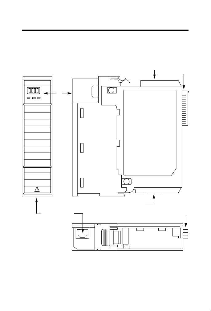
Identify Module Components
Use the following figure to identify the external features of the 1756-EWEB
module.
Front View
Web +
LINK NET OK
RJ45 Cable
Connector located
on underside of module
31272-M
Front
Panel
Front
of
Module
Side View
MAC ID Label (may be inside here or
at bottom as shown below)
MAC ID Label (may be inside here
or at top as shown above)
Bottom View
Backplane
Connector
Backplane
Connector
Publication
1756-IN588A-EN-P - February 2004
Page 9
EtherNet/IP Web Server Module 9
Prepare the Chassis for Module Installation
Before you install the module, you must install and connect a ControlLogixTM
chassis and power supply.
Power
Supply
-
1756-A4
Chassis
For information on installing these products, refer to the publications listed in
the following table.
Chassis
Ty pe
Series B: 1756-A4, -A7, -A10, -A13 Pub. No.
Chassis
Installation
1756-IN080
Power
Supply
1756-PA72/B Pub. No.
1756-PB72/B
1756-PA75/A Pub. No.
1756-PB75/A
Power Supply
Installation
1756-5.67
1756-5.78
Publication
1756-IN588A-EN-P - February 2004
Page 10

10 EtherNet/IP Web Server Module
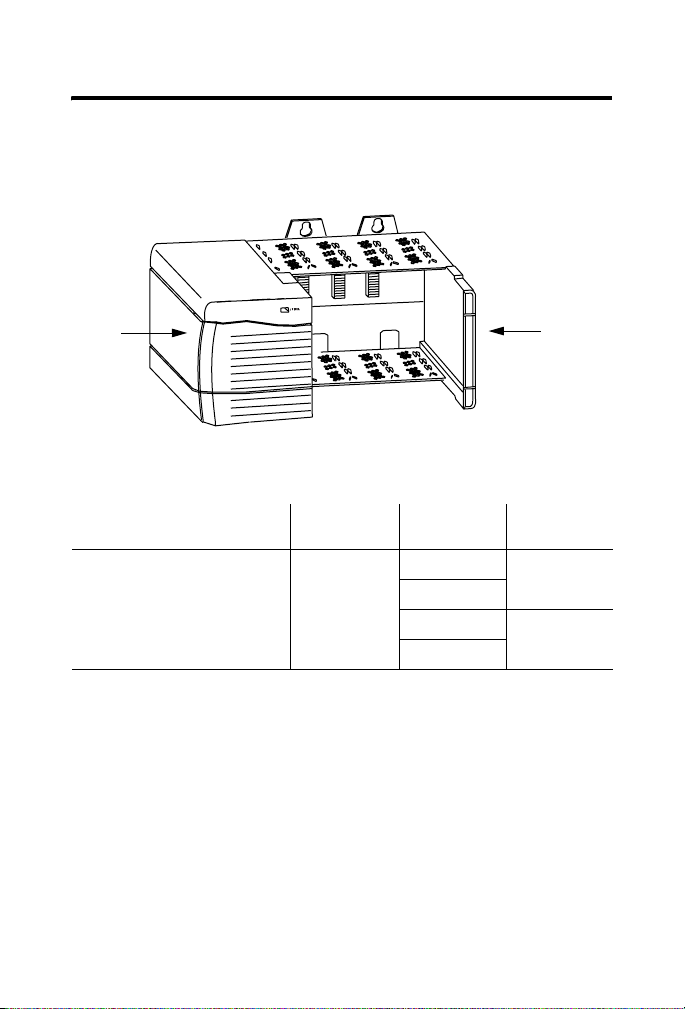
Determine Module Slot Location
You can install the module in any slot in the ControlLogix chassis. You can
also install multiple 1756-EWEB modules in the same chassis. The figure
below shows chassis slot numbering in a 4-slot chassis. Slot 0 is the first slot
and is always the left-most slot in the rack (the first slot to the right of the
power supply)
.
Power Supply
Slot 0
Slot 1
Slot 2
Slot 3
Chassis
WARNING
Publication
When you insert or remove the module while
backplane power is on, an electrical arc can occur. This
could cause an explosion in hazardous location
installations.
Be sure that power is removed or the area is
nonhazardous before proceeding. Repeated electrical
arcing causes excessive wear to contacts on both the
module and its mating connector. Worn contacts may
create electrical resistance that can affect module
operation.
1756-IN588A-EN-P - February 2004
Page 11

Install the Module
2
Slide the module into the chassis. Make sure the
module backplane connector properly connects to
the chassis backplane.
EtherNet/IP Web Server Module 11
Align the circuit board with top and
bottom guides in the chassis.
Circuit Board
31275-M
1
3
The module is properly installed when
it is flush with the power supply or other
installed modules.
Publication
31276-M
1756-IN588A-EN-P - February 2004
Page 12

12 EtherNet/IP Web Server Module
Removing or Replacing the Module (when applicable)
1
Push on upper and lower module tabs
to disengage them.
31277-M
IMPORTANT
Publication
31278-M
2
Slide module out of chassis.
If you are replacing an existing module with an identical
one, and you want to resume identical system operation,
you must install the new module in the same slot.
1756-IN588A-EN-P - February 2004
Page 13

EtherNet/IP Web Server Module 13
Installing or Removing the Module Under Power
This module is designed to be installed or removed while chassis power is
applied.
WARNING
Wire the EtherNet/IP Connector
Use an RJ45 connector to connect to the EtherNet/IP network. Wire the
connector according to the following illustration:
For detailed EtherNet/IP connection information, see the EtherNet/IP Media
Planning and Installation Guide, publication number ENET-IN001.
When you insert or remove the module while backplane
power is on, an electrical arc can occur. This could cause
an explosion in hazardous location installations.
Be sure that power is removed or the area is
nonhazardous before proceeding. Repeated electrical
arcing causes excessive wear to contacts on both the
module and its mating connector. Worn contacts may
create electrical resistance that can affect module
operation.
8 ------ NC
7 ------ NC
6 ------ RD5 ------ NC
4 ------ NC
3 ------ RD+
2 ------ TD1 ------ TD+
8
1
RJ 45
Publication
1756-IN588A-EN-P - February 2004
Page 14

14 EtherNet/IP Web Server Module
Connect the Module to the EtherNet/IP Network
WARNING
If you connect or disconnect the communications
cable with power applied to this module or any device
on the network, an electrical arc can occur. This could
cause an explosion in hazardous location installations.
Attach the RJ45 connector to the EtherNet/IP port on the bottom of the
module as shown below:
RJ-45 EtherNet/IP
connector
Connect the cable
here.
This is the bottom, back of the module that
connects into the chassis.
Publication
1756-IN588A-EN-P - February 2004
Page 15

EtherNet/IP Web Server Module 15
IMPORTANT
Apply Chassis Power
We recommend connecting the module to the
network via a 100MB EtherNet/IP switch, which will
reduce collisions and lost packets and increase
network bandwidth. For detailed EtherNet/IP
connection information, see the following
publications:
• EtherNet/IP Performance and Application Guide,
publication ENET-AP001
• EtherNet/IP Media Planning and Installation Guide,
publication ENET-IN001
31280-M
Publication
1756-IN588A-EN-P - February 2004
Page 16

16 EtherNet/IP Web Server Module
Check Power Supply and Module Status
Check the LED indicators and alphanumeric display to determine if the
power supply and module are operating properly.
Power Supply
indicator is GREEN.
31281-M
LINK
Web +
LINK NET OK
NET
OK indicator is
red during self-test,
then green.
Alphanumeric
Display
The alphanumeric display should cycle through the following states: “TEST PASS - OK - REV x.x,” where “x.x” is the module’s firmware revision. The
display then alternates between “OK” and the module’s EtherNet/IP address.
Publication
1756-IN588A-EN-P - February 2004
Page 17

EtherNet/IP Web Server Module 17
Obtain an IP Address
By default, the web server module is DHCP enabled. If you connect the web
server module to a network that has a DHCP server, that server will assign a
dynamic IP address to the web server module and the four-digit display on the
front of the web server module will display each of the four numbers of the IP
address.
If your network does not have a DHCP server, use one of the methods
described in chapter
2 of the EtherNet/IP Web Server Module User Manual,
publication ENET-UM527 to assign an IP address to the web server module.
Access the Home Page of the Module
From your web browser, enter the IP address of the web server module. The
module displays its Home page
Specify the IP address of
the web server module in
the Address window of your
web browser.
.
This is the module’s
home page..
Publication
1756-IN588A-EN-P - February 2004
Page 18

18 EtherNet/IP Web Server Module
Log Into the Module
Many of the features of the web server module require you to log in with
appropriate access. If you select a feature, such as New Data View, the web
server module prompts you to enter your user name and password. The
default user name is “Administrator” with no password (leave the Password
field blank).
Default Access:
User Name: Administrator
(not case sensitive)
Password:
(leave blank, no password)
You can set up as many as 25 user accounts. Each account can have read, read
and write, or administrator access. For more information, see the EtherNet/IP
Web Server Module User Manual, publication ENET-UM527.
Publication
1756-IN588A-EN-P - February 2004
Page 19

EtherNet/IP Web Server Module 19
Confirm the Network Configuration
On the Administrator Settings → Device Configuration → Network
Configuration page, you can verify the IP address and other network settings.
For more information, see the EtherNet/IP Web Server Module User Manual,
publication ENET-UM527.
Using the Web Server Module
To help familiarize yourself with the web server module, some of the tasks
you can accomplish include:
• Create a data view
• Configure email
• Configure the time server
• Enable/disable other services
These tasks are described in the following section.
Publication
1756-IN588A-EN-P - February 2004
Page 20

20 EtherNet/IP Web Server Module
Create a Data View
Before you can create a data view in the web server, the tags you want to view
must exist in the controller that is local (in the same chassis) to the web server
module. The tags in the controller must be controller-scoped. For example,
create:
TEST
type DINT
controller-scope
value 123
To create a create a data view, you need Administrator or Write access. You
create a data view from the Data Views → New Data View page.
1. In the Create Data View window, specify a name for the data view and
enter a description (optional).
2. In the New Data View window, specify at least one tag (EWEB_test
in this example). You must specify the:
• slot number of the controller
• tag name (exactly as it is in the controller)
• type of tag
• how to display the tag data
• access limit of the data view
Publication
1756-IN588A-EN-P - February 2004
Page 21

EtherNet/IP Web Server Module 21
3. Click on the Add button to add the tag to the data view
Continue adding as many tags as you want to configure.
4. Click Create View.
5. From the Data Views → Data View page, select the data view you just
created.
6. Click on the filename link to view the tags in this data view.
7. Type the new value in the box next to the tag and click the Update
button. This changes the value in the controller. You can use
TM
RSLogix
5000 programming software to verify that the value
changed.
Publication
1756-IN588A-EN-P - February 2004
Page 22

22 EtherNet/IP Web Server Module
Note: To change a data value, you need Administrator or Write access.
For more information, see the EtherNet/IP Web Server Module User Manual,
publication ENET-UM527A.
Configure Email
You configure the SMTP server that manages email on the Administrative
Settings → Device Configuration → Network Configuration page.
You can enter and send an email from the Send an Email link on the web
server module. Or you can have a controller execute a MSG instruction that
initiates email and email through the web server module.
For more information, see the EtherNet/IP Web Server Module User Manual,
publication ENET-UM527.
Publication
1756-IN588A-EN-P - February 2004
Page 23

EtherNet/IP Web Server Module 23
Configure the Time Server
You select the method the web server module uses to maintain an accurate
date and time stamp on the Administrative Settings → Server Management →
Time Settings page. This makes sure that files you save to the web server
module have accurate date and time stamps.
Select:
• SNTP Time Server to get the date and time from an SNTP server on
the network.
• Query Controller to get the date and time from the local controller.
• Manual Time Entry to specify you own date and time.
For more information, see the EtherNet/IP Web Server Module User Manual,
publication ENET-UM527.
Publication
1756-IN588A-EN-P - February 2004
Page 24

24 EtherNet/IP Web Server Module
Enable/Disable Other Services
You can enable other services from the Administrative Settings → Device
Configuration → Device Services page.
Select the services you want to use. Enable the:
• FTP (File Transfer Protocol) service to allow file transfers to and
from the web server module
• SNMP (Simple Network Management Protocol) service if your
system uses SNMP management software
• SMTP (Simple Mail Transfer Protocol) to service email
• CIP (Common Industrial Protocol) Bridge EtherNet/IP to Backplane
service to allow navigation and bridging to only the web server
module and not to any other device in the chassis
• CIP (Common Industrial Protocol) Bridge Backplane to EtherNet/IP
service to allow navigation and bridging to the web server module and
to any other device in the chassis
• XML/ASP (Extended Markup Language/Active Server Page) service
to allow web access to the module
For more information, see the EtherNet/IP Web Server Module User Manual,
publication ENET-UM527.
Publication
1756-IN588A-EN-P - February 2004
Page 25

EtherNet/IP Web Server Module 25
Troubleshooting the Module
If the alphanumeric display and LED indicators do not sequence through the
expected states refer to the following troubleshooting tables. The three
bi-color (red/green) LED status indicators on the 1756-EWEB module
provide diagnostic information about the module and its connections to the
network.
NET (Network) Status Indicator
The Network Status LED provides the following information:
State Status Description
Off Not Powered,
No IP Address
Flashing Green No Connections Module has obtained an IP address,
Green CIP Connections Module has an IP address and at least
Flashing Red Connection Timeout One or more of the connections in
Red Duplicate IP Address Module has detected that its IP
Module is not powered, or does not
have an IP address.
• Verify there is chassis power and
the module is completely inserted
into the chassis and backplane.
• Make sure the module has been
configured.
but has no established connections.
one established connection.
which the module is the target has
timed out.
address is already in use. Assign a
unique IP address to the module.
Publication
1756-IN588A-EN-P - February 2004
Page 26

26 EtherNet/IP Web Server Module
Link Status Indicator
The Link Status LED provides the following information:
State Status Description
Off No data transmission Module is not ready to communicate.
Green Ready Module is ready to communicate.
Flashing Green Data transmission in
progress
Module is communicating over the
network.
OK Status Indicator
The OK Status LED provides the following module information:
State Status Description
Off No Power Module does not have 24V DC power.
Flashing Green Standby Module is not configured.
Green Operational Module is operating correctly.
Flashing Red Minor Fault A recoverable fault has been detected.
Red Major Fault An unrecoverable fault has been
Flashing Red and Green Self Test Module performing power-up self-test.
Verify there is chassis power and the
module is completely inserted into
chassis and backplane.
This could be caused by an error in the
configuration.
detected. Recycle power to the module.
If this does not clear the fault, replace
the module.
Where to Find More Information on Configuring the Module
For more details on configuring your web server module, refer to the
EtherNet/IP Web Server Module User Manual, publication ENET-UM527A.
Publication
1756-IN588A-EN-P - February 2004
Page 27

EtherNet/IP Web Server Module 27
Specifications
Specification: Value:
Module Location Any slot in the ControlLogix chassis
Maximum Backplane
Current Load
Power Dissipation 3.65W maximum
Isolation voltage
(continuous-voltage
withstand rating)
Operational Temperature IEC 60068-2-1 (Test Ad, Operating Cold),
Storage Temperature IEC 60068-2-1 (Test Ab, Un-packaged Non-operating Cold),
Relative Humidity IEC 60068-2-30 (Test Db, Un-packaged Non-operating Damp
Vibration IEC 60068-2-6 (Test Fc, Operating):
Operating Shock IEC 60068-2-27 (Test Ea, Unpackaged Shock):
Non-Operating Shock IEC 60068-2-27 (Test Ea, Unpackaged Shock):
Emissions CISPR 11:
700mA @ 5.1V DC
3mA @ 24V DC from I/O chassis backplane
50V
IEC 60068-2-2 (Test Bd, Operating Dry Heat),
IEC 60068-2-14 (Test Nb, Operating Thermal Shock),
0 to 60°C (32 to 140°F)
IEC 60068-2-2 (Test Bb, Un-packaged Non-operating Dry
Heat),
IEC 60068-2-14 (Test Na, Un-packaged Non-operating Thermal
Shock):
-40 to 85°C (-40 to 185°F)
Heat):
5 to 95% non-condensing
2g @ 10-500Hz
30g
50g
Group 1, Class A
Publication
1756-IN588A-EN-P - February 2004
Page 28

28 EtherNet/IP Web Server Module
Specification: Value:
ESD Immunity IEC 61000-4-2:
Radiated RF Immunity IEC 61000-4-3:
EFT/B Immunity IEC 61000-4-4:
Surge Transient Immunity ±2kV line-earth(CM) on shielded ports
Conducted RF Immunity IEC 61000-4-6:
Enclosure Type Rating None (open-style)
Conductors - Wiring
Category
EtherNet/IP Connector RJ45 Category 5
6kV contact discharges
8kV air discharges
10V/m with 1kHz sine-wave 80%AM from 30MHz to
1000MHz
10V/m with 200Hz 50% Pulse 100%AM at 900Mhz
±2kV at 5kHz on communications ports
±2kV line-earth unshielded ports
10Vrms with 1kHz sine-wave 80%AM from 150kHz to 80MHz
21 - on communications ports
Publication
1756-IN588A-EN-P - February 2004
Page 29

EtherNet/IP Web Server Module 29
Specification: Value:
User Manual Publication ENET-UM527A
Certifications
(when product is marked)
UL: UL Listed Industrial Control Equipment
CSA: CSA Certified Process Control Equipment
CSA Certified Process Control Equipment for Class I,
Division 2 Group A,B,C,D Hazardous Locations
CE2: European Union 89/336/EEC EMC Directive, compliant
with:
EN 50081-2; Industrial Emissions
EN 61326; Meas./Control/Lab., Industrial Requirements
EN 61000-6-2; Industrial Immunity
EN 61000-6-4; Industrial Emissions
C-Tick2: Australian Radiocommunications Act, compliant
with:
AS/NZS CISPR 11; Industrial Emissions
EEx‡: European Union 94/9/EC ATEX Directive, compliant
with:
EN 50021; Potentially Explosive Atmospheres, Protection
"n" (Zone 2)
EtherNet/IP: ODVA conformance tested to EtherNet/IP
specifications
1
Use this Conductor Category information for planning conductor routing. Refer to Publication 1770-4.1,
"Industrial Automation Wiring and Grounding Guidelines".
2
See the Product Certification link at www.ab.com for Declarations of Conformity, Certificates, and other
certification details.
ControlLogix and RSLogix are trademarks of Rockwell Automation.
EtherNet/IP is a registered tradem ark of Digital Equipment Corporation, Intel and Xerox.
This product incorporates code f rom GoAhead Software, Inc., Copyright © 2004 GoAhead Software, Inc. A ll Rights Reserved.
Publication
1756-IN588A-EN-P - February 2004
Page 30

Rockwell Automation Support
Rockwell Automation provides technical information on the web to assist you
in using our products. At http://support.rockwellautomation.com, you can
find technical manuals, a knowledge base of FAQs, technical and application
notes, sample code and links to software service packs, and a MySupport
feature that you can customize to make the best use of these tools.
For an additional level of technical phone support for installation,
configuration and troubleshooting, we offer TechConnect Support programs.
For more information, contact your local distributor or Rockwell Automation
representative, or visit http://support.rockwellautomation.com.
Installation Assistance
If you experience a problem with a hardware module within the first 24 hours
of installation, please review the information that's contained in this manual.
You can also contact a special Customer Support number for initial help in
getting your module up and running:
United States 1.440.646.3223 Monday – Friday, 8am – 5pm EST
Outside United States Please contact your local Rockwell Automation representative for any
New Product Satisfaction Return
Rockwell tests all of our products to ensure that they are fully operational
when shipped from the manufacturing facility. However, if your product is not
functioning and needs to be returned:
United States Contact your distributor. You must provide a Customer Support case number
Outside United States Please contact your local Rockwell Automation representative for return
technical support issues.
(see phone number above to obtain one) to your distributor in order to
complete the return process.
procedure.
Publication 1756-IN588A-EN-P - February 2004 PN 957824-76
Copyright © 2004 Rockwell Automation , Inc. All rights reserved . Printed in the U.S.A.
 Loading...