

Page 1

Installation Instructions
EtherNet/IP Modules
Catalog Numbers 1756-ENBT, 1756-EN2F, 1756-EN2T, 1756-EN2TR, 1756-EN2TXT, 1756-EN2TRXT, 1756-EN2TSC,
1756-EN3TR, 1756-EWEB, 1768-ENBT, 1768-EWEB, 1769-AENTR
Page 2
Important User Information
Read this document and the documents listed in the additional resources section about installation, configuration, and
operation of this equipment before you install, configure, operate, or maintain this product. Users are required to
familiarize themselves with installation and wiring instructions in addition to requirements of all applicable codes, laws,
and standards.
Activities including installation, adjustments, putting into service, use, assembly, disassembly, and maintenance are required
to be carried out by suitably trained personnel in accordance with applicable code of practice.
If this equipment is used in a manner not specified by the manufacturer, the protection provided by the equipment may be
impaired.
In no event will Rockwell Automation, Inc. be responsible or liable for indirect or consequential damages resulting from the
use or application of this equipment.
The examples and diagrams in this manual are included solely for illustrative purposes. Because of the many variables and
requirements associated with any particular installation, Rockwell Automation, Inc. cannot assume responsibility or
liability for actual use based on the examples and diagrams.
No patent liability is assumed by Rockwell Automation, Inc. with respect to use of information, circuits, equipment, or
software described in this manual.
Reproduction of the contents of this manual, in whole or in part, without written permission of Rockwell Automation,
Inc., is prohibited.
Throughout this manual, when necessary, we use notes to make you aware of safety considerations.
WARNING: Identifies information about practices or circumstances that can cause an explosion in a hazardous environment,
which may lead to personal injury or death, property damage, or economic loss.
ATTENTION: Identifies information about practices or circumstances that can lead to personal injury or death, property
damage, or economic loss. Attentions help you identify a hazard, avoid a hazard, and recognize the consequence.
IMPORTANT
Identifies information that is critical for successful application and understanding of the product.
Labels may also be on or inside the equipment to provide specific precautions.
SHOCK HAZARD: Labels may be on or inside the equipment, for example, a drive or motor, to alert people that dangerous
voltage may be present.
BURN HAZARD: Labels may be on or inside the equipment, for example, a drive or motor, to alert people that surfaces may
reach dangerous temperatures.
ARC FLASH HAZARD: Labels may be on or inside the equipment, for example, a motor control center, to alert people to
potential Arc Flash. Arc Flash will cause severe injury or death. Wear proper Personal Protective Equipment (PPE). Follow ALL
Regulatory requirements for safe work practices and for Personal Protective Equipment (PPE).
Allen-Bradley, Rockwell Software, Rockwell Automation, CompactLogix, ControlLogix, RSLinx , RSLogix, ControlLogix-XT, Logix5000, ControlFLASH, Compact I/O, and Studio 5000 are trademarks of Rockwell
Automation, Inc.
Trademarks not belonging to Rockwell Automation are property of their respective companies.
Page 3

Summary of Changes
This manual contains new and updated information. Changes throughout this
revision are marked by change bars, as shown to the right of this paragraph.
New and Updated Information
This table contains the changes made in this revision.
Topic Page
Added the 1769 adapter installation information 55
Added the 1769 adapter status indicators 95
Rockwell Automation Publication ENET-IN002F-EN-P - January 2014 3
Page 4

Summary of Changes
Notes:
4 Rockwell Automation Publication ENET-IN002F-EN-P - January 2014
Page 5

Table of Contents
Preface
Install a 1756 EtherNet/IP
Communication Module
Studio 5000 Environment . . . . . . . . . . . . . . . . . . . . . . . . . . . . . . . . . . . . . . . . . . 9
Additional Resources . . . . . . . . . . . . . . . . . . . . . . . . . . . . . . . . . . . . . . . . . . . . . 10
Chapter 1
Installation Summary. . . . . . . . . . . . . . . . . . . . . . . . . . . . . . . . . . . . . . . . . . . . . 14
Grounding Considerations. . . . . . . . . . . . . . . . . . . . . . . . . . . . . . . . . . . . 14
Determine Module Slot Location. . . . . . . . . . . . . . . . . . . . . . . . . . . . . . . . . . 14
Set the Network IP Address on a Module . . . . . . . . . . . . . . . . . . . . . . . . . . 15
Set the Network IP Address with the Rotary Switches . . . . . . . . . . . 17
Set the Network IP Address with the BOOTP/DHCP Server. . . . 18
Set the Network IP Address with RSLinx Software or the
Studio 5000 Environment. . . . . . . . . . . . . . . . . . . . . . . . . . . . . . . . . . . . . 21
Reset the Module IP Address to a Factory Default Value. . . . . . . . . 25
Install the Module. . . . . . . . . . . . . . . . . . . . . . . . . . . . . . . . . . . . . . . . . . . . . . . . 25
Wire the Module. . . . . . . . . . . . . . . . . . . . . . . . . . . . . . . . . . . . . . . . . . . . . . . . . 26
Use the following information to wire the module. . . . . . . . . . . . . . . 26
Connect the Module to an EtherNet/IP Network via an
RJ45 Connection. . . . . . . . . . . . . . . . . . . . . . . . . . . . . . . . . . . . . . . . . . . . . 26
Connect the Module to an EtherNet/IP Network via a
Fiber Connector . . . . . . . . . . . . . . . . . . . . . . . . . . . . . . . . . . . . . . . . . . . . . 28
Download the Add-on Profile. . . . . . . . . . . . . . . . . . . . . . . . . . . . . . . . . . . . . 29
Connect to the Module via the USB Port . . . . . . . . . . . . . . . . . . . . . . . . . . 30
Download the Firmware . . . . . . . . . . . . . . . . . . . . . . . . . . . . . . . . . . . . . . . . . . 31
Digitally Signed Firmware. . . . . . . . . . . . . . . . . . . . . . . . . . . . . . . . . . . . . 32
Apply Chassis Power and Check Status Indicators . . . . . . . . . . . . . . . . . . 32
Install or Remove the Module Under Power. . . . . . . . . . . . . . . . . . . . . . . . 33
Install a 1768 EtherNet/IP
Communication Module
Chapter 2
Installation Summary. . . . . . . . . . . . . . . . . . . . . . . . . . . . . . . . . . . . . . . . . . . . . 37
Grounding Considerations. . . . . . . . . . . . . . . . . . . . . . . . . . . . . . . . . . . . 38
Set the Network IP Address. . . . . . . . . . . . . . . . . . . . . . . . . . . . . . . . . . . . . . . 38
Set the Network IP Address with a BOOTP/DHCP Server. . . . . . 40
Set the Network IP Address with RSLinx Software or the
Studio 5000 Environment. . . . . . . . . . . . . . . . . . . . . . . . . . . . . . . . . . . . . 42
Reset the Module IP Address to a Factory Default Value. . . . . . . . . 46
Install the Module. . . . . . . . . . . . . . . . . . . . . . . . . . . . . . . . . . . . . . . . . . . . . . . . 46
Mount the Module with Screws . . . . . . . . . . . . . . . . . . . . . . . . . . . . . . . 46
Mount on a DIN Rail. . . . . . . . . . . . . . . . . . . . . . . . . . . . . . . . . . . . . . . . . 47
Wire the Module. . . . . . . . . . . . . . . . . . . . . . . . . . . . . . . . . . . . . . . . . . . . . . . . . 48
Connect the Module to an EtherNet/IP Network via an
RJ45 Connection. . . . . . . . . . . . . . . . . . . . . . . . . . . . . . . . . . . . . . . . . . . . . 48
Download the Add-on Profile. . . . . . . . . . . . . . . . . . . . . . . . . . . . . . . . . . . . . 49
Download the Firmware . . . . . . . . . . . . . . . . . . . . . . . . . . . . . . . . . . . . . . . . . . 50
Apply Chassis Power and Check Status Indicators . . . . . . . . . . . . . . . . . . 51
Remove the Module . . . . . . . . . . . . . . . . . . . . . . . . . . . . . . . . . . . . . . . . . . . . . . 52
Rockwell Automation Publication ENET-IN002F-EN-P - January 2014 5
Page 6

Table of Contents
Install a 1769 EtherNet/IP Adapter
Chapter 3
System Configuration . . . . . . . . . . . . . . . . . . . . . . . . . . . . . . . . . . . . . . . . . . . . 57
Example Configurations. . . . . . . . . . . . . . . . . . . . . . . . . . . . . . . . . . . . . . . 58
Installation Summary . . . . . . . . . . . . . . . . . . . . . . . . . . . . . . . . . . . . . . . . . . . . . 59
Grounding Considerations . . . . . . . . . . . . . . . . . . . . . . . . . . . . . . . . . . . . 59
Set the Network IP Address . . . . . . . . . . . . . . . . . . . . . . . . . . . . . . . . . . . . . . . 59
Set the Network IP Address with the Rotary Switches . . . . . . . . . . . 61
Set the Network IP Address with a BOOTP/DHCP Server . . . . . . 62
Set the Network IP Address with RSLinx or the
Studio 5000 Environment . . . . . . . . . . . . . . . . . . . . . . . . . . . . . . . . . . . . . 64
Reset the IP Address to a Factory Default Value . . . . . . . . . . . . . . . . . 67
Install the Adapter in a 1769 System . . . . . . . . . . . . . . . . . . . . . . . . . . . . . . . 68
Adapter Description . . . . . . . . . . . . . . . . . . . . . . . . . . . . . . . . . . . . . . . . . . 68
System Assembly . . . . . . . . . . . . . . . . . . . . . . . . . . . . . . . . . . . . . . . . . . . . . 69
Mount the Adapter and I/O Modules . . . . . . . . . . . . . . . . . . . . . . . . . . 70
Wire the Adapter. . . . . . . . . . . . . . . . . . . . . . . . . . . . . . . . . . . . . . . . . . . . . . . . . 72
Ground the Adapter . . . . . . . . . . . . . . . . . . . . . . . . . . . . . . . . . . . . . . . . . . 72
Connect the Module to an EtherNet/IP Network via an
RJ45 Connection . . . . . . . . . . . . . . . . . . . . . . . . . . . . . . . . . . . . . . . . . . . . . 72
Use the Module in a Device-level Ring (DLR) Network. . . . . . . . . . 73
Download the Add-on Profile . . . . . . . . . . . . . . . . . . . . . . . . . . . . . . . . . . . . . 74
Download the Firmware . . . . . . . . . . . . . . . . . . . . . . . . . . . . . . . . . . . . . . . . . . 75
Enable the Web Pages. . . . . . . . . . . . . . . . . . . . . . . . . . . . . . . . . . . . . . . . . . . . . 76
Disable Web Pages. . . . . . . . . . . . . . . . . . . . . . . . . . . . . . . . . . . . . . . . . . . . 76
Remove or Replace the Adapter. . . . . . . . . . . . . . . . . . . . . . . . . . . . . . . . . . . . 77
Configure a Workstation to Operate
on an EtherNet/IP Network
USB Communication
1756 EtherNet/IP Status Indicators
1768 EtherNet/IP Module Status
Indicators
Chapter 4
Select the Driver. . . . . . . . . . . . . . . . . . . . . . . . . . . . . . . . . . . . . . . . . . . . . . . . . . 79
Configure the Ethernet Communication Driver . . . . . . . . . . . . . . . . . . . . 80
Chapter 5
Set Up the Hardware . . . . . . . . . . . . . . . . . . . . . . . . . . . . . . . . . . . . . . . . . . . . . 84
Configure a Module via the USB Port. . . . . . . . . . . . . . . . . . . . . . . . . . . . . . 84
Set Up a USB Driver. . . . . . . . . . . . . . . . . . . . . . . . . . . . . . . . . . . . . . . . . . 85
Load Firmware through a USB Port. . . . . . . . . . . . . . . . . . . . . . . . . . . . . . . . 87
Appendix A
. . . . . . . . . . . . . . . . . . . . . . . . . . . . . . . . . . . . . . . . . . . . . . . . . . . . . . . . . . . . . . . . . 89
Appendix B
. . . . . . . . . . . . . . . . . . . . . . . . . . . . . . . . . . . . . . . . . . . . . . . . . . . . . . . . . . . . . . . . . 93
6 Rockwell Automation Publication ENET-IN002F-EN-P - January 2014
Page 7

1769 EtherNet/IP Adapter Status
Indicators
Table of Contents
Appendix C
. . . . . . . . . . . . . . . . . . . . . . . . . . . . . . . . . . . . . . . . . . . . . . . . . . . . . . . . . . . . . . . . . 95
Appendix D
Fiber Cable and LC Connector
Index
Specifications . . . . . . . . . . . . . . . . . . . . . . . . . . . . . . . . . . . . . . . . . . . . . . . . . . . . 97
. . . . . . . . . . . . . . . . . . . . . . . . . . . . . . . . . . . . . . . . . . . . . . . . . . . . . . . . . . . . . . . . . 99
Rockwell Automation Publication ENET-IN002F-EN-P - January 2014 7
Page 8

Table of Contents
8 Rockwell Automation Publication ENET-IN002F-EN-P - January 2014
Page 9

Preface
This manual describes how to install and start up EtherNet/IP module systems
with Logix5000
Use this manual if you program applications that use an EtherNet/IP network
with one of these Logix5000 controllers:
• CompactLogix
• ControlLogix
You should also understand the following:
• Networking concepts
• How to the use Studio 5000
• How to use RSLinx
controllers.
environment
Classic programming software
Studio 5000 Environment
The Studio 5000 Engineering and Design Environment combines engineering
and design elements into a common environment. The first element in the Studio
5000 environment is the Logix Designer application. The Logix Designer
application is the rebranding of RSLogix
5000 software and continues to be the
product to program Logix5000 controllers for discrete, process, batch, motion,
safety, and drive-based solutions.
The Studio 5000 environment is the foundation for the future of Rockwell
Automation
engineering design tools and capabilities. This environment is the
one place for design engineers to develop all of the elements of their control
system.
Rockwell Automation Publication ENET-IN002F-EN-P - January 2014 9
Page 10

Preface
Additional Resources
For more information on the products described in this publication, use these
resources.
Resource Description
Ethernet Design Considerations
Reference Manual,
publication
EtherNet/IP Secure Communication
User Manual, publication
EtherNet/IP Network Configuration User
Manual, publication
EtherNet/IP Embedded Switch
Technology Application Guide,
publication
EtherNet/IP Media Planning and
Installation Manual
This manual is available from the Open
DeviceNet Vendor Association (ODVA)
at:
ENET-RM002
ENET-UM003
ENET-UM001
ENET-AP005
http://www.odva.org.
Provides details about how to use EtherNet/IP communication modules
with Logix5000 controllers and communicate with other devices on the
EtherNet/IP network.
Provides information on system architecture, configuring secure
communication, and diagnostics.
Describes how you can use EtherNet/IP communication modules with
your Logix5000 controller and communicate with various devices on the
Ethernet network.
Provides details about how to install, configure, and maintain linear and
Device-level Ring (DLR) networks by using Rockwell Automation
EtherNet/IP devices equipped with embedded switch technology.
Provides details about how to use the required media components and
how to plan for, install, verify, troubleshoot, and certify your
EtherNet/IP network.
You can view or download publications at
http:/www.rockwellautomation.com/literature/. To order paper copies of
technical documentation, contact your local Allen-Bradley distributor or
Rockwell Automation sales representative.
10 Rockwell Automation Publication ENET-IN002F-EN-P - January 2014
Page 11
Chapter 1
Install a 1756 EtherNet/IP Communication
Module
Topic Page
Installation Summary 14
Determine Module Slot Location 14
Set the Network IP Address on a Module 15
Install the Module 25
Wire the Module 26
Download the Add-on Profile 29
Connect to the Module via the USB Port 30
Download the Firmware 31
Apply Chassis Power and Check Status Indicators 32
Install or Remove the Module Under Power 33
ATTENTION: Environment and Enclosure
This equipment is intended for use in a Pollution Degree 2 industrial environment, in overvoltage Category II applications (as defined
in IEC 60664-1), at altitudes up to 2000 m (6562 ft) without derating.
This equipment is not intended for use in residential environments and may not provide adequate protection to radio communication
services in such environments.
This equipment is supplied as open-type equipment. It must be mounted within an enclosure that is suitably designed for those
specific environmental conditions that will be present and appropriately designed to prevent personal injury resulting from
accessibility to live parts. The enclosure must have suitable flame-retardant properties to prevent or minimize the spread of flame,
complying with a flame spread rating of 5VA or be approved for the application if nonmetallic. The interior of the enclosure must be
accessible only by the use of a tool. Subsequent sections of this publication may contain additional information regarding specific
enclosure type ratings that are required to comply with certain product safety certifications.
In addition to this publication, see the following:
• Industrial Automation Wiring and Grounding Guidelines, publication
• NEMA 250 and IEC 60529, as applicable, for explanations of the degrees of protection provided by enclosures
1770-4.1, for additional installation requirements
Rockwell Automation Publication ENET-IN002F-EN-P - January 2014 11
Page 12
Chapter 1 Install a 1756 EtherNet/IP Communication Module
North American Hazardous Location Approval
The following information applies when operating this
equipment in hazardous locations.
Products marked "CL I, DIV 2, GP A, B, C, D" are suitable for use in Class
I Division 2 Groups A, B, C, D, Hazardous Locations and nonhazardous
locations only. Each product is supplied with markings on the rating
nameplate indicating the hazardous location temperature code.
When combining products within a system, the most adverse
temperature code (lowest "T" number) may be used to help
determine the overall temperature code of the system. Combinations
of equipment in your system are subject to investigation by the local
Authority Having Jurisdiction at the time of installation.
WARNING: EXPLOSION HAZARD
• Do not disconnect equipment unless power has
been removed or the area is known to be
nonhazardous.
• Do not disconnect connections to this equipment
unless power has been removed or the area is
known to be nonhazardous. Secure any external
connections that mate to this equipment by using
screws, sliding latches, threaded connectors, or
other means provided with this product.
• Substitution of components may impair suitability
for Class I, Division 2.
• If this product contains batteries, they must only
be changed in an area known to be nonhazardous.
Informations sur l’utilisation de cet équipement en
environnements dangereux.
Les produits marqués "CL I, DIV 2, GP A, B, C, D" ne conviennent qu'à
une utilisation en environnements de Classe I Division 2 Groupes A, B,
C, D dangereux et non dangereux. Chaque produit est livré avec des
marquages sur sa plaque d'identification qui indiquent le code de
température pour les environnements dangereux. Lorsque plusieurs
produits sont combinés dans un système, le code de température le
plus défavorable (code de température le plus faible) peut être utilisé
pour déterminer le code de température global du système. Les
combinaisons d'équipements dans le système sont sujettes à
inspection par les autorités locales qualifiées au moment de
l'installation.
AVERTISSEMENT: RISQUE D’EXPLOSION –
• Couper le courant ou s'assurer que
l'environnement est classé non dangereux avant
de débrancher l'équipement.
• Couper le courant ou s'assurer que
l'environnement est classé non dangereux avant
de débrancher les connecteurs. Fixer tous les
connecteurs externes reliés à cet équipement à
l'aide de vis, loquets coulissants, connecteurs
filetés ou autres moyens fournis avec ce produit.
• La substitution de composants peut rendre cet
équipement inadapté à une utilisation en
environnement de Classe I, Division 2.
• S'assurer que l'environnement est classé non
dangereux avant de changer les piles.
12 Rockwell Automation Publication ENET-IN002F-EN-P - January 2014
Page 13
Install a 1756 EtherNet/IP Communication Module Chapter 1
European Hazardous Location Approval
The following applies when the product bears the Ex Marking.
This equipment is intended for use in potentially explosive atmospheres as defined by European Union Directive 94/9/EC and has been found to comply with the
Essential Health and Safety Requirements relating to the design and construction of Category 3 equipment intended for use in Zone 2 potentially explosive
atmospheres, given in Annex II to this Directive.
Compliance with the Essential Health and Safety Requirements has been assured by compliance with EN 60079-15 and EN 60079-0.
WARNING: Special Conditions for Safe Use
• This equipment shall be mounted in an ATEX Zone 2 certified enclosure with a minimum ingress protection rating of at least
IP54 (as defined in EN 60529) and used in an environment of not more than Pollution Degree 2 (as defined in EN 60664-1)
when applied in Zone 2 environments. The enclosure must be accessible only by the use of a tool.
• This equipment shall be used within its specified ratings defined by Rockwell Automation.
• Secure any external connections that mate to this equipment by using screws, sliding latches, threaded connectors, or other
means provided with this product.
• Do not disconnect equipment unless power has been removed or the area is known to be nonhazardous.
• The USB port is intended for temporary local programming purposes only and not intended for permanent connection and do
not use the USB port in hazardous locations.
• Provision shall be made to prevent the rated voltage from being exceeded by transient disturbances of more than 140% of the
rated voltage when applied in Zone 2 environments.
• This equipment must be used only with ATEX-certified Rockwell Automation backplanes.
• The instructions in the user manual shall be observed.
ATTENTION: Prevent Electrostatic Discharge
This equipment is sensitive to electrostatic discharge, which can cause internal damage and affect normal operation. Follow these
guidelines when you handle this equipment:
• Touch a grounded object to discharge potential static.
• Wear an approved grounding wriststrap.
• Do not touch connectors or pins on component boards.
• Do not touch circuit components inside the equipment.
• Use a static-safe workstation, if available.
• Store the equipment in appropriate static-safe packaging when not in use.
ATTENTION: This equipment is not resistant to sunlight or other sources of UV radiation.
Rockwell Automation Publication ENET-IN002F-EN-P - January 2014 13
Page 14
Chapter 1 Install a 1756 EtherNet/IP Communication Module
Installation Summary
Follow these steps to install a communication module in a 1756 ControlLogix
chassis.
1. Set the Network IP Address on a Module.
Determine Module Slot Location.
2.
Install the Module.
3.
Connect the Module to an EtherNet/IP Network via an RJ45
4.
Connection.
or
Connect the Module to an EtherNet/IP Network via a Fiber Connector.
Download the Add-on Profile.
5.
Connect to the Module via the USB Port.
6.
Download the Firmware. - Optional
7.
Apply Chassis Power and Check Status Indicators.
8.
Install or Remove the Module Under Power. - Optional
9.
Grounding Considerations
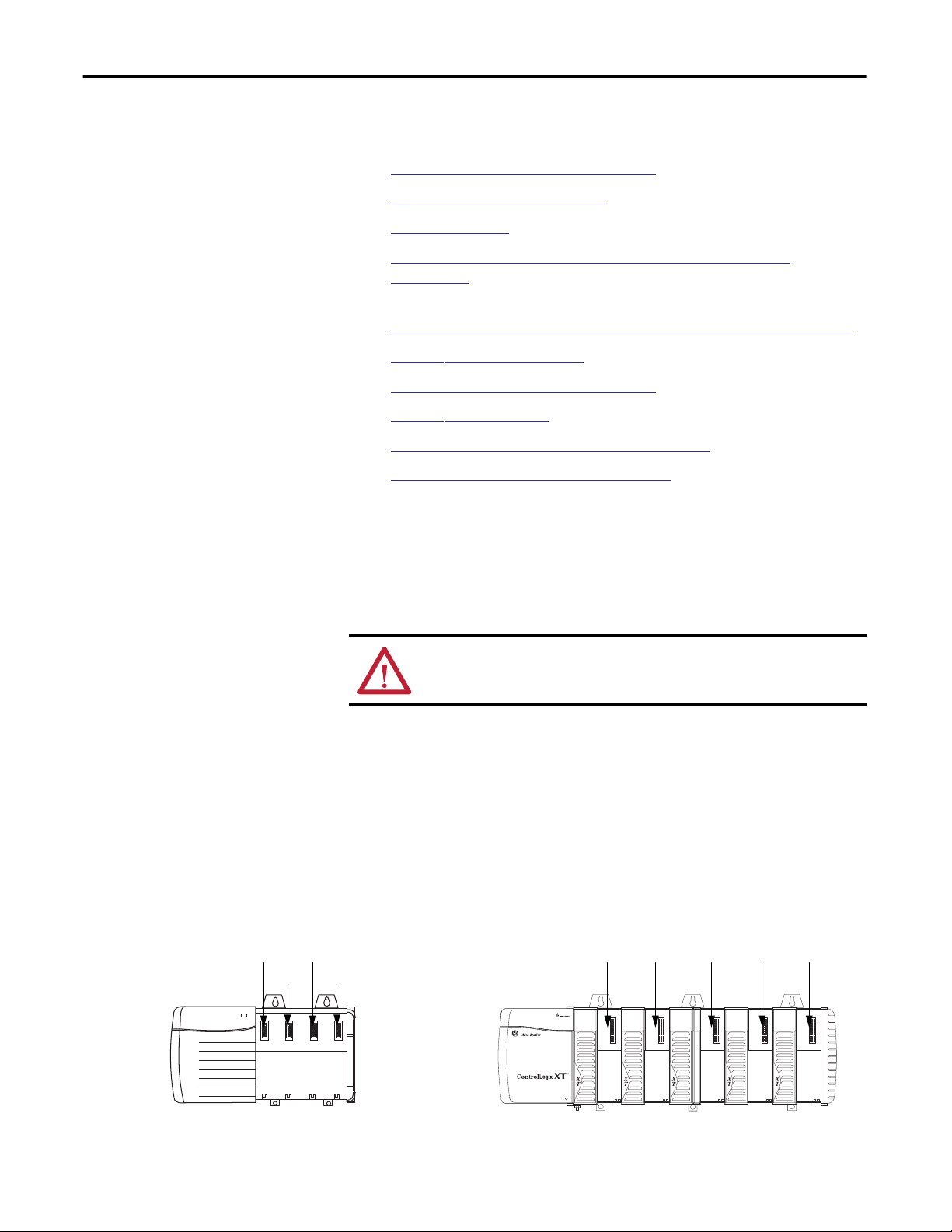
Determine Module Slot Location
ControlLogix Chassis ControlLogix-XT Chassis
Slot 2Slot 0
Slot 1 Slot 3
The grounding and bonding must be of equal potential between all devices in the
communication coverage area.
ATTENTION: If this equipment is used in a manner not specified by the
manufacturer, the protection provided by the equipment may be impaired.
Install the communication module in any slot in a ControlLogix or
ControlLogix-XT™ chassis. You can install multiple communication modules in
the same chassis.
This example shows chassis slot numbering in a 4-slot ControlLogix chassis and a
5-slot ControlLogix-XT chassis. Slot 0 is the first slot and is always the leftmost
slot in the chassis.
Slot 0 Slot 4Slot 1 Slot 2 Slot 3
20806
14 Rockwell Automation Publication ENET-IN002F-EN-P - January 2014
31896
Page 15

Install a 1756 EtherNet/IP Communication Module Chapter 1
Set the Network IP Address on a Module
To operate an EtherNet/IP communication module on an EtherNet/IP network,
you must set a network IP address.
The IP address uniquely identifies the module. The IP address is in the form
xxx.xxx.xxx.xxx where each xxx is a number from 000…254.
There are some reserved values that you cannot use as the first octet in the
address. These numbers are examples of values you cannot use:
• 001.xxx.xxx.xxx
• 127.xxx.xxx.xxx
• 223 to 255.xxx.xxx.xxx
The specific reserved values that cannot be used vary by application.
For more information about configuring an EtherNet/IP network, see
EtherNet/IP Network Configuration User Manual, publication
Depending on the 1756 EtherNet/IP communication module, you can use some
or all of these tools to set the network Internet Protocol (IP) address:
• Rotary switches - The 1756-ENBT and 1756-EWEB modules do not offer
rotary switches. If you are using either of these modules, skip Set the
Network IP Address with the Rotary Switches on
the Network IP Address with the BOOTP/DHCP Server on
page 17 and go to Set
ENET-UM001.
page 18.
• Bootstrap Protocol (BOOTP)/Dynamic Host Configuration Protocol
(DHCP) server
• RSLinx Classic software
• the Studio 5000 environment
The module uses these tools sequentially to set the IP address.
The 1756 EtherNet/IP communication modules are shipped with
this configuration:
• BOOTP/DHCP enabled
• Rotary switches set to 999 - when applicable
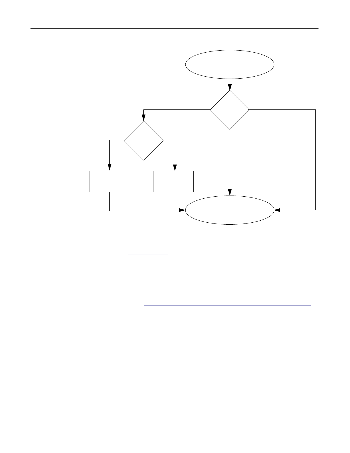
This graphic shows the process used to set your module’s IP address.
Rockwell Automation Publication ENET-IN002F-EN-P - January 2014 15
Page 16
Chapter 1 Install a 1756 EtherNet/IP Communication Module
Figure 1 - How Your Module’s IP Address Is Set
Module Powerup
Module uses IP address
stored in nonvolatile
memory.
Is DHCP or
BOOTP
enabled?
Switches set
from
001…254?
YesNo
Module requests
address from DHCP/
BOOTP server.
Module has an IP
address.
YesNo
If you need to reset your module’s settings to its factory default settings during
normal module operation, see
Reset the Module IP Address to a Factory Default
Value on page 25.
These tools are used in this sequence to set the network IP address.
1.
Set the Network IP Address with the Rotary Switches
Set the Network IP Address with the BOOTP/DHCP Server
2.
Set the Network IP Address with RSLinx Software or the Studio 5000
3.
Environment
16 Rockwell Automation Publication ENET-IN002F-EN-P - January 2014
Page 17
Install a 1756 EtherNet/IP Communication Module Chapter 1
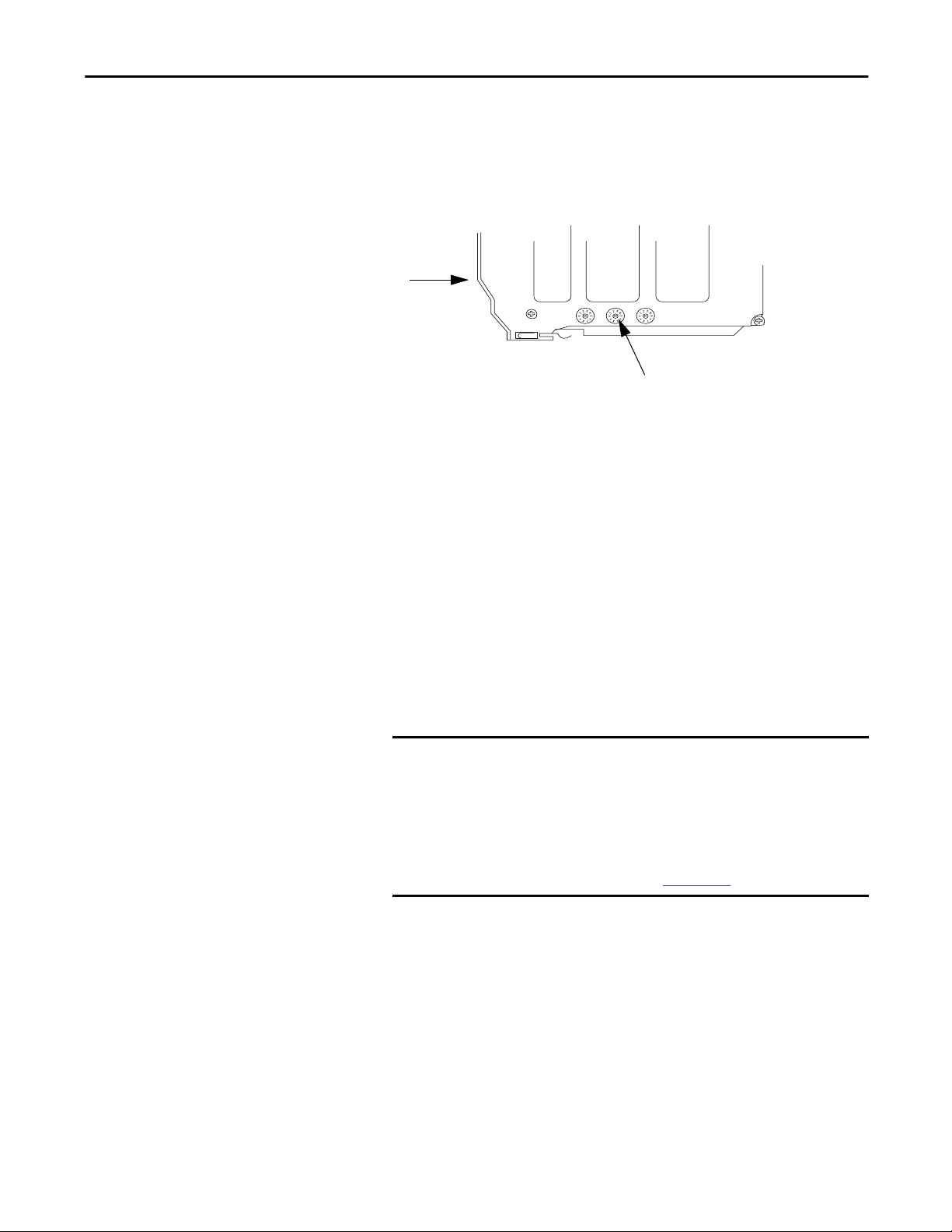
Set the Network IP Address with the Rotary Switches
This graphic shows the rotary switches on a 1756 EtherNet/IP communication
module. Depending on the module, the switches are on the top or the side of the
module.
Front of
Module
Rotary Switches
32454
At powerup, the module reads the rotary switches to determine if they are set to a
valid number for the last portion of the IP address, that is, if the numbers are in
the range from 001…254.
If the settings are a valid number, these conditions result:
• IP address = 192.168.1.xxx (where xxx represents the switch settings)
• Subnet mask = 255.255.255.0
• Gateway address
= 192.168.1.1 for firmware revision 5.008 or later
= 0.0.0.0 for firmware revision 5.007 or earlier
IMPORTANT
The gateway address of 192.168.1.1 applies only to the 1756-EN2T,
1756-EN2TR, 1756-EN2TRXT, 1756-EN2F, 1756-EN2TSC, and
1756-EN3TR modules with firmware revision 5.008 or later. Other
modules use the gateway address of 0.0.0.0 with firmware revision
5.007 or earlier.
For more information, see the Ethernet Design Considerations
Reference Manual, publication
ENET-RM002.
• The module does not have a host name assigned, nor does it use any
Domain Name System
We recommend that you set the rotary switches to a valid number before
installing the module.
If either of these conditions exist, the module attempts to use the BOOTP/
DHCP server to set the IP address:
• Rotary switches are not set to a valid number.
• Module does not have rotary switches.
Rockwell Automation Publication ENET-IN002F-EN-P - January 2014 17
Page 18
Chapter 1 Install a 1756 EtherNet/IP Communication Module
Set the Network IP Address with the BOOTP/DHCP Server
The BOOTP/DHCP server is a standalone server you can use to set an IP
address. When used, the BOOTP/DHCP server sets an IP address and other
Transport Control Protocol (TCP) parameters.
You can use the BOOTP/DHCP server to set the module’s IP address if one of
these conditions exists at powerup:
Access the BOOTP/DHCP server from one of these locations:
• The module’s rotary switches are not set to a valid number and the module
is BOOTP/DHCP enabled.
• The module does not have rotary switches and the module is
BOOTP/DHCP enabled.
• Programs > Rockwell Software > BOOTP-DHCP Server
If you have not installed the server, you can download and install it from
http://www.ab.com/networks/ethernet/bootp.html.
• Tools directory on the Studio 5000 environment installation CD
IMPORTANT
Before you start the BOOTP/DHCP server, make sure you have the
module’s hardware (MAC) address. The hardware address is on a sticker
on the side of the communication module and uses an address in a
format similar to the following:
00-00-BC-14-55-35
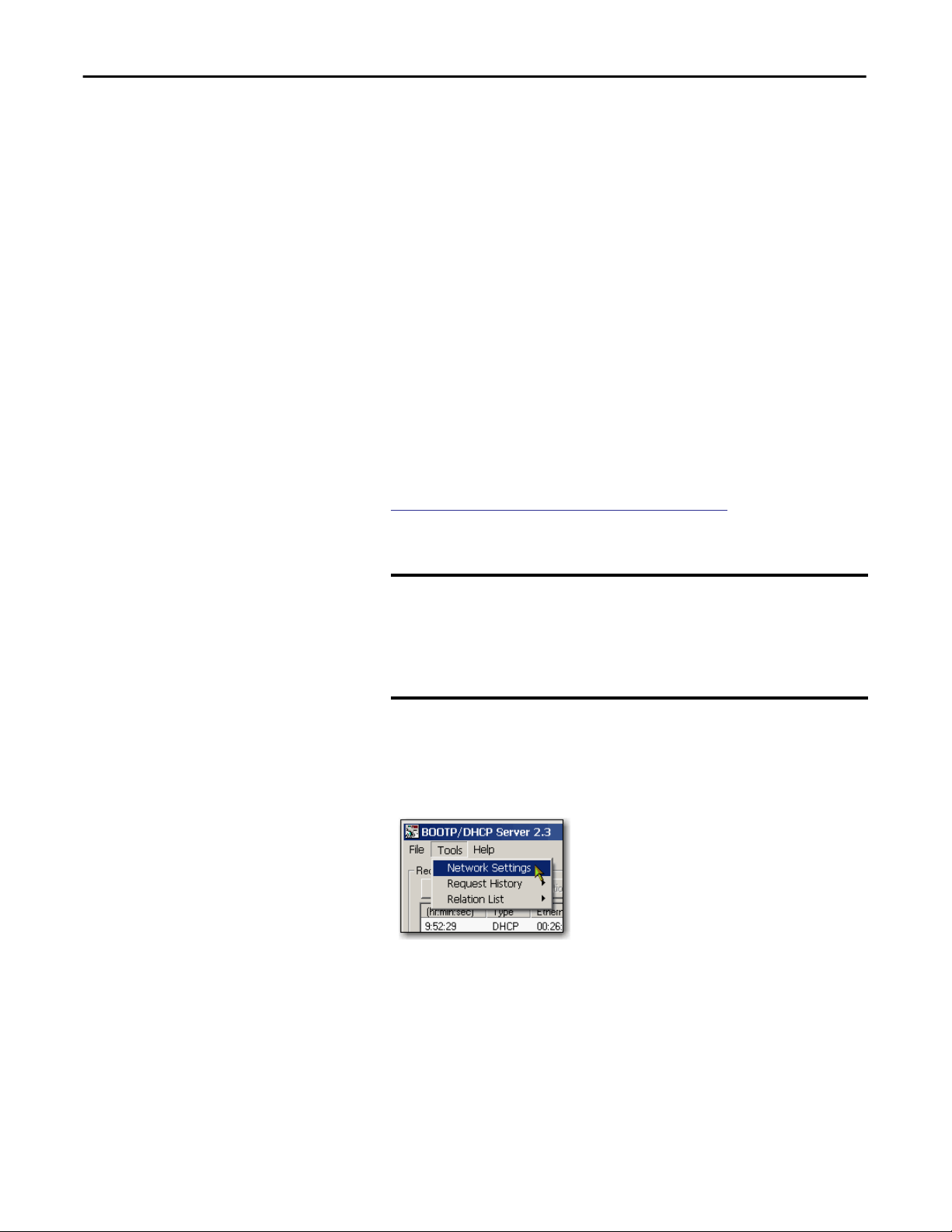
Follow these steps to set the module’s IP address with a BOOTP/DHCP server.
1. Start the BOOTP/DHCP software.
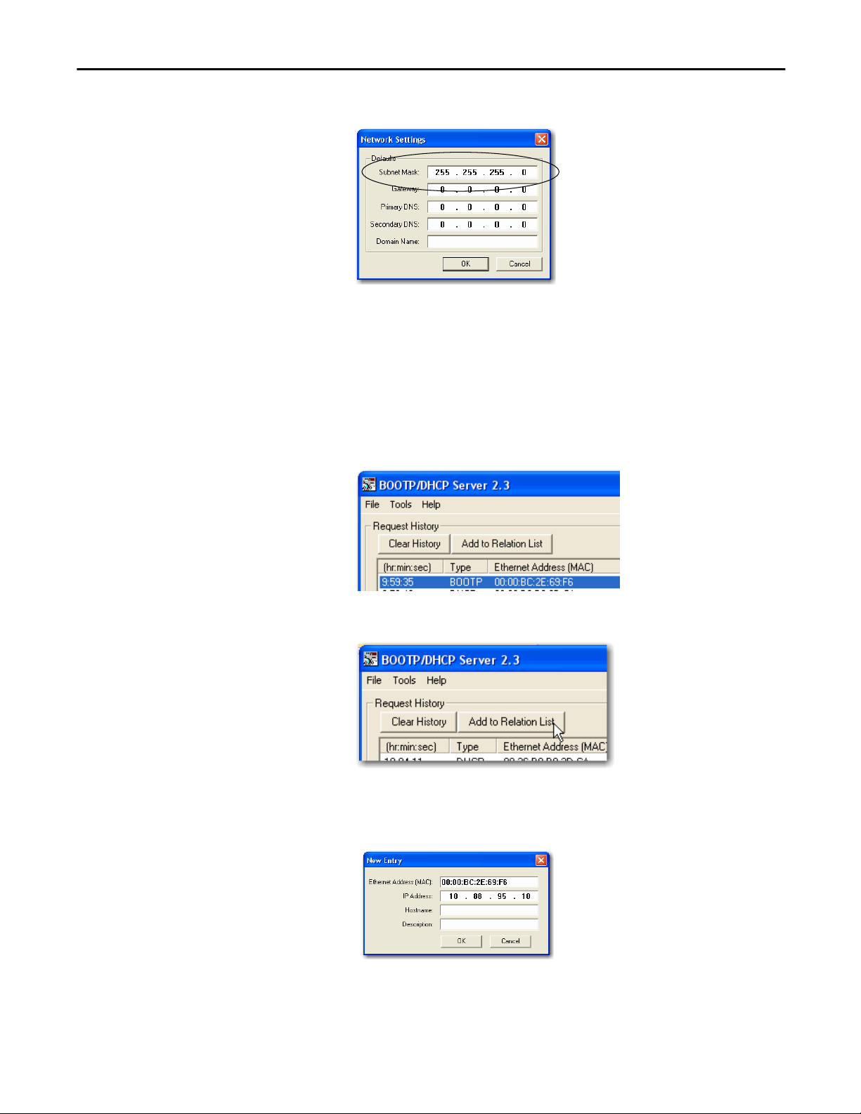
2. From the Tools menu, choose Network Settings.
18 Rockwell Automation Publication ENET-IN002F-EN-P - January 2014
Page 19
Install a 1756 EtherNet/IP Communication Module Chapter 1
3. Type the Subnet Mask of the network.
The Gateway address, Primary and/or Secondary DNS address, and
Domain Name fields are optional.
4. Click OK.
The Request History panel appears with the hardware addresses of all
modules issuing BOOTP requests.
5. Select the appropriate module.
6. Click Add to Relation List.
The New Entry dialog box appears.
7. Type an IP Address, Hostname, and Description for the module.
8. Click OK.
Rockwell Automation Publication ENET-IN002F-EN-P - January 2014 19
Page 20
Chapter 1 Install a 1756 EtherNet/IP Communication Module
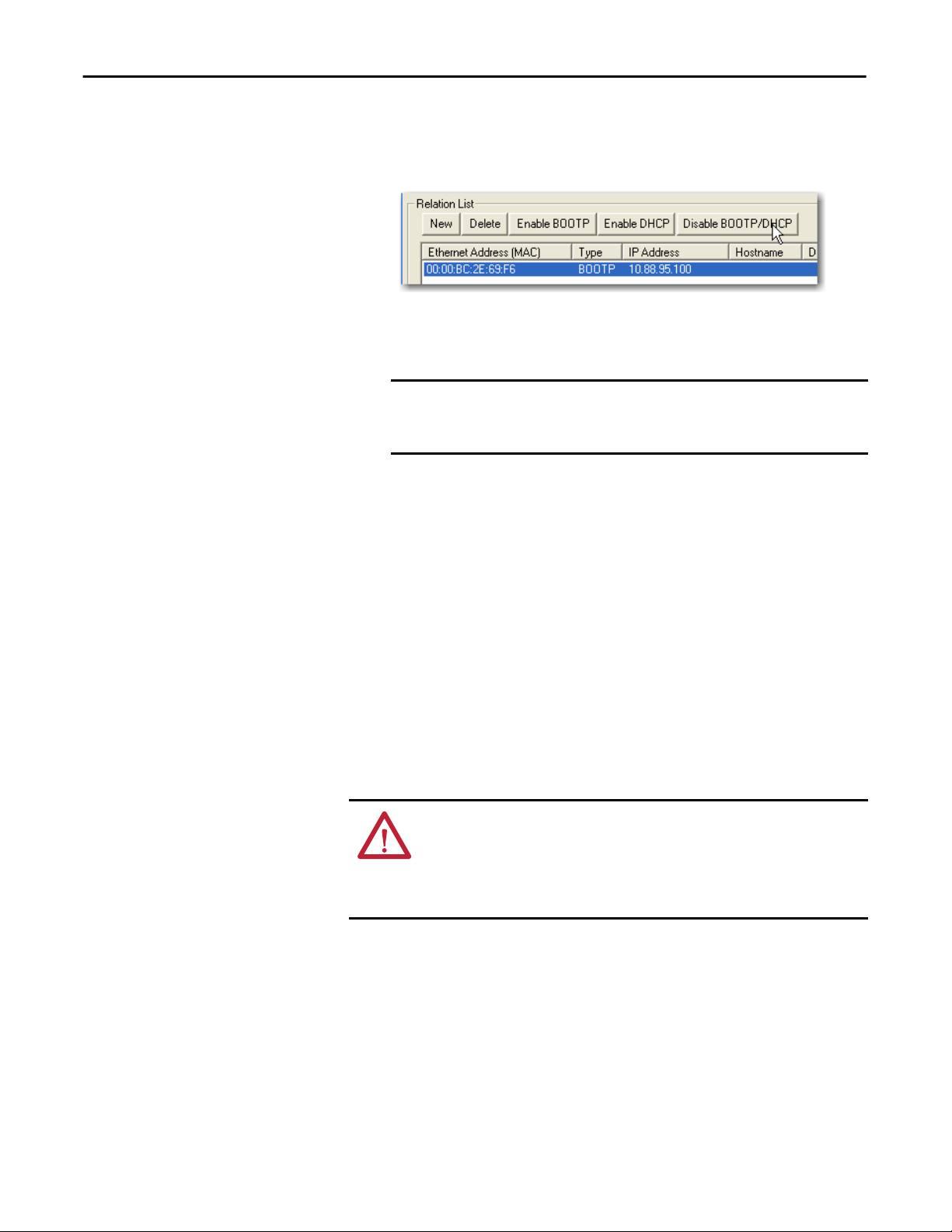
9. To permanently assign this configuration to the module, wait for the
module to appear in the Relation List panel and select it.
10. Click Disable BOOTP/DHCP.
When power is recycled, the module uses the assigned configuration and
does not issue a BOOTP request.
IMPORTANT
If you do not click Disable BOOTP/DHCP, on a power cycle, the host
controller clears the current IP configuration and begins sending
BOOTP requests again.
Use DHCP Software
Dynamic Host Configuration Protocol (DHCP) software automatically assigns
IP addresses to client stations logging onto a TCP/IP network. DHCP is based
on BOOTP and maintains some backward compatibility. The main difference is
that BOOTP allows for manual configuration (static), while DHCP allows for
both static and dynamic allocation of network addresses and configurations to
newly attached modules.
Be cautious when using DHCP software to configure a module. A BOOTP
client, such as the EtherNet/IP communication modules, can start from a DHCP
server only if the DHCP server is specifically written to also handle BOOTP
queries. This is specific to the DHCP software package used. Consult your
system administrator to see if a DHCP package supports BOOTP commands
and manual IP allocation.
ATTENTION: The EtherNet/IP communication module must be assigned a
fixed network address. The IP address of this module must not be dynamically
provided.
Failure to observe this precaution may result in unintended machine motion or
loss of process control.
20 Rockwell Automation Publication ENET-IN002F-EN-P - January 2014
Page 21

Install a 1756 EtherNet/IP Communication Module Chapter 1
Set the Network IP Address with RSLinx Software or the Studio 5000 Environment
This table describes when to set the network IP address with RSLinx software or
the Studio 5000 environment.
Conditions Software to Use Page
• A BOOTP server is not available.
• The EtherNet/IP communication module is connected to another
NetLinx network.
The Studio 5000 project is online with a controller that communicates to or
through the EtherNet/IP communication module.
Consider these factors when you determine how to set the network IP address:
• Network isolation from or integration into the plant/enterprise network
• Network size - For large networks, isolated networks, it might be more
convenient and safer to use a BOOTP/DHCP server rather than the
Studio 5000 environment or RSLinx software. The BOOTP/DHCP
server also limits the possibility of assigning duplicate IP addresses.
RSLinx 22
Studio 5000 environment 24
• Company policies and procedures dealing with plant-floor network
installation and maintenance
• Level of involvement by IT personnel in plant floor network installation
and maintenance
• Type of training offered to control engineers and maintenance personnel
If you use the Rockwell Automation BOOTP or DHCP server in an uplinked
subnet where an enterprise DHCP server exists, a module may get an address
from the enterprise server before the Rockwell Automation utility even sees the
module. You might have to disconnect from the uplink to set the address and
configure the module to retain its static address before reconnecting to the
uplink. This is not a problem if you have node names configured in the module
and leave DHCP enabled.
Rockwell Automation Publication ENET-IN002F-EN-P - January 2014 21
Page 22
Chapter 1 Install a 1756 EtherNet/IP Communication Module
Set the Network IP Address with RSLinx Software
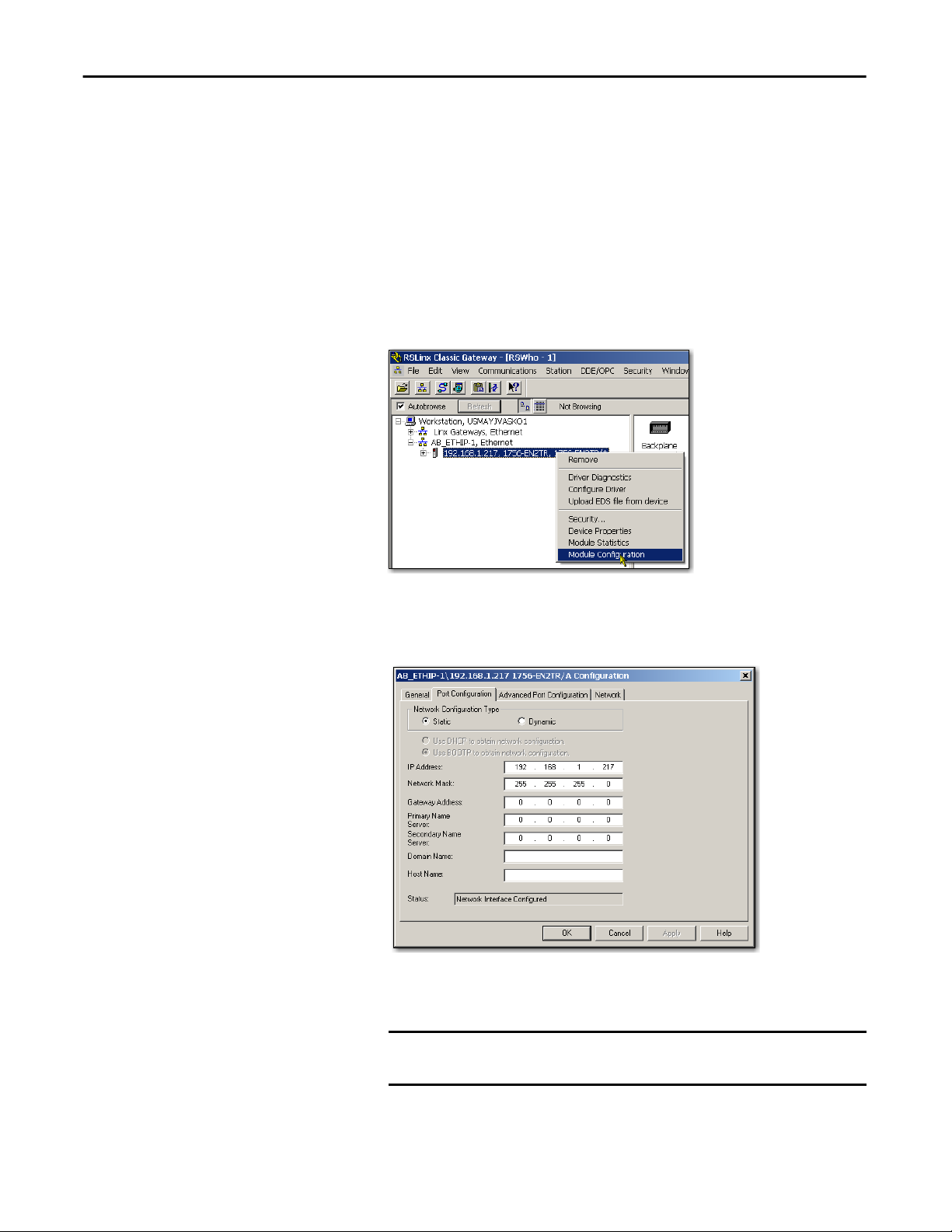
Follow these steps to use RSLinx software to set the communication module’s
IP address.
1. From the Communications menu, choose RSWho.
The RSWho dialog box appears.
2. Navigate to the Ethernet network.
3. Right-click the EtherNet/IP module and choose Module Configuration.
The Module Configuration dialog box appears.
4. Click the Port Configuration tab.
5. For Network Configuration Type, click Static to permanently assign this
configuration to the port.
IMPORTANT
If you select Dynamic, on a power cycle, the controller clears the
current IP configuration and resumes sending BOOTP requests.
6. Type this information in the appropriate fields:
22 Rockwell Automation Publication ENET-IN002F-EN-P - January 2014
Page 23

Install a 1756 EtherNet/IP Communication Module Chapter 1
• In the IP Address field, type the IP address.
• In the Network Mask field, type the network mask address.
• In the Gateway Address field, type the gateway address.
• In the Primary Name Server field, type the IP address.
• In the Secondary Name Server field, type the IP address.
• In the Domain Name field, type the domain name.
• In the Host Name field, type the host name.
7. Configure the port settings.
To Then
Use the default port speed and
duplex settings
Manually configure your port’s
speed and duplex settings
Leave Auto-negotiate port speed and duplex checked.
This setting determines the actual speed and duplex setting.
Follow these steps.
1. Clear the Auto-negotiate port speed and duplex checkbox.
2. From the Current Port Speed pull-down menu, choose a port
speed.
3. From the Current Duplex pull-down menu, choose the appropriate
Duplex value, that is, Half Duplex or Full Duplex.
IMPORTANT
8. Click OK.
Consider the following when you configure the module’s port settings:
• If the module is connected to an unmanaged switch, leave Autonegotiate port speed and duplex checked or communication may
be impaired.
• If you are forcing the port speed and duplex with a managed
switch, the corresponding port of the managed switch must be
forced to the same settings or the module will fail.
Rockwell Automation Publication ENET-IN002F-EN-P - January 2014 23
Page 24
Chapter 1 Install a 1756 EtherNet/IP Communication Module
Set the Network IP Address with the Studio 5000 Environment
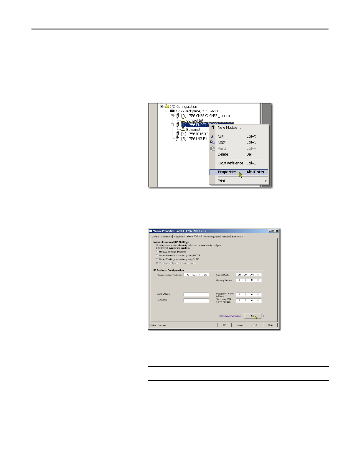
Follow these steps to use the Studio 5000 environment to set the communication
module’s IP address.
1. In the Controller Organizer, right-click the EtherNet/IP module and
choose Properties.
The Module Properties dialog box appears.
2. Click the Port Configuration tab.
3. In the IP Address field, type the IP address.
4. In the other fields, type the other network parameters, if needed.
IMPORTANT
The fields that appear vary from one EtherNet/IP module to another.
5. Click Set.
6. Click OK.
24 Rockwell Automation Publication ENET-IN002F-EN-P - January 2014
Page 25
Install a 1756 EtherNet/IP Communication Module Chapter 1
Reset the Module IP Address to a Factory Default Value
You can reset the module’s IP address to its factory default value with the
following methods:
• If the module has rotary switches, set the switches to 888 and cycle power.
• If the module does not have rotary switches, use a MSG instruction to the
reset the IP address.
For more information on resetting the network IP address to its default
value with a MSG instruction, see Knowledgebase Answer ID 55362, at
https://rockwellautomation.custhelp.com/app/answers/detail/a_id/
55362 (login required).
Install the Module
Follow these steps to install the module.
WARNING: When you insert or remove the module while backplane power is
on, an electrical arc can occur. This could cause an explosion in hazardous
location installations.
Be sure that power is removed or the area is nonhazardous before proceeding.
Repeated electrical arcing causes excessive wear to contacts on both the module
and its mating connector. Worn contacts may create electrical resistance that can
affect module operation.
ATTENTION: Use caution when handling the module. One side of the module is
a heat sink, and may be very hot.
IMPORTANT
Your module will resemble one of the modules shown in the illustrations. Note
that the extreme temperature (XT) versions of the modules are not shown in the
illustrations.
Rockwell Automation Publication ENET-IN002F-EN-P - January 2014 25
Page 26
Chapter 1 Install a 1756 EtherNet/IP Communication Module
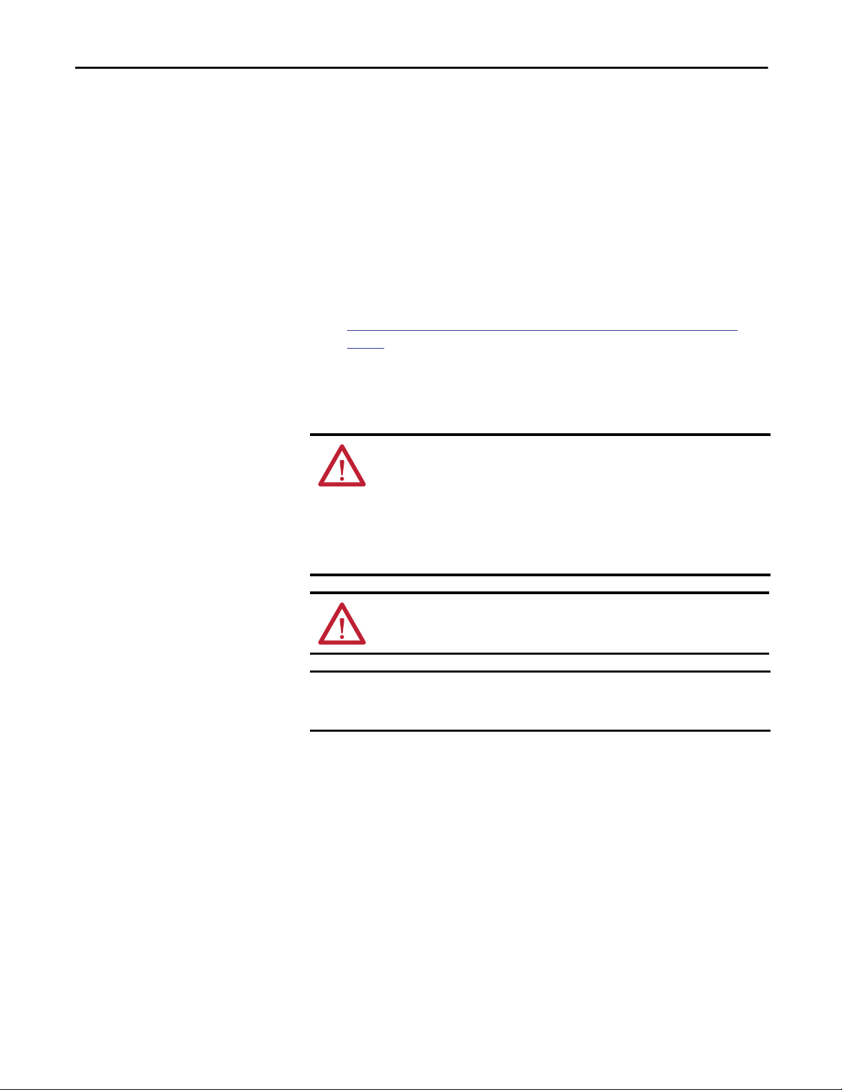
7. Align the circuit board with top and bottom guides in the chassis.
32455
8. Slide the module into the chassis.
Wire the Module
Make sure the module backplane connector properly connects to the
chassis backplane. Note that the module is properly installed when it is
flush with the power supply or other installed modules.
Use the following information to wire the module.
Connect the Module to an EtherNet/IP Network via an RJ45 Connection
These 1756 EtherNet/IP communication modules use an RJ45 connector to
connect to an EtherNet/IP network:
• 1756-ENBT - ControlLogix EtherNet/IP bridge module
• 1756-EN2T - ControlLogix EtherNet/IP bridge module
• 1756-EN2TSC- ControlLogix EtherNet/IP Secure Communication
module
26 Rockwell Automation Publication ENET-IN002F-EN-P - January 2014
Page 27
Install a 1756 EtherNet/IP Communication Module Chapter 1
• 1756-EN2TR - ControlLogix EtherNet/IP 2-port module
• 1756-EN2TRXT- ControlLogix-XT EtherNet/IP module
• 1756-EN2TXT - ControlLogix-XT EtherNet/IP module
• 1756-EN3TR - ControlLogix EtherNet/IP 2-port module
• 1756-EWEB - ControlLogix EtherNet/IP Web Server module
Wire the RJ45 connector as shown.
8 ------ NC
7 ------ NC
6 ------ RD5 ------ NC
4 ------ NC
3 ------ RD+
2 ------ TD1 ------ TD+
8
1
R
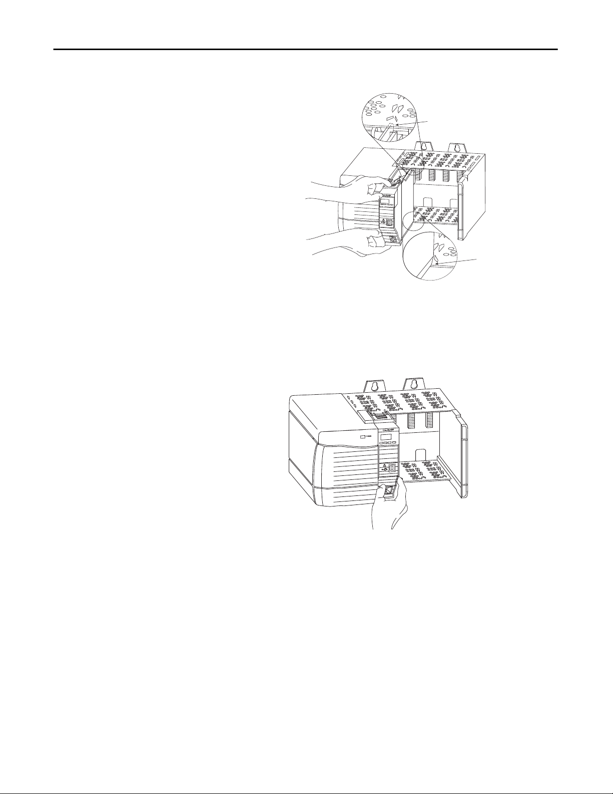
Follow these steps to connect the module to the network.
WARNING: If you connect or disconnect the communication cable with power
applied to this module or any device on the network, an electrical arc can
occur. This could cause an explosion in hazardous location installations.
Be sure that power is removed or the area is nonhazardous before proceeding.
1. Attach the cable with the RJ45 connector to the Ethernet port on the
module as shown.
Dual-port
Module
Dual-port Module
(Single port not shown)
Single-port
Module
2. Attach the other end of the cable to the devices in your network.
32457
Rockwell Automation Publication ENET-IN002F-EN-P - January 2014 27
Page 28
Chapter 1 Install a 1756 EtherNet/IP Communication Module
Connect the Module to an EtherNet/IP Network via a Fiber Connector
The 1756-EN2F ControlLogix EtherNet/IP module uses a fiber connector to
connect to an EtherNet/IP network.
Attach the LC2 multi-mode fiber cable to the Ethernet port on the bottom of the
module as shown.
ATTENTION: Do not look directly into the optical port. Under certain
conditions, viewing the optical port may expose the eye to hazard. When
viewed under some conditions, the optical port may expose the eye beyond
the maximum permissible exposure recommendations.
Class 1 laser product. Laser radiation is present when the system is open and
interlocks bypassed. Only trained and qualified personnel should be allowed to
install, replace, or service this equipment.
28 Rockwell Automation Publication ENET-IN002F-EN-P - January 2014
Page 29
Install a 1756 EtherNet/IP Communication Module Chapter 1
Download the Add-on Profile
If a module has a later firmware revision for the communication module than
recognized in the most current version of the Logix Designer application, you
need to download the Add-on Profile (AOP) for the communication module so
it can be recognized in the Controller Organizer.
Complete these steps to download and install an AOP.
1. Go to the Rockwell Automation Web site at
http://www.rockwellautomation.com/.
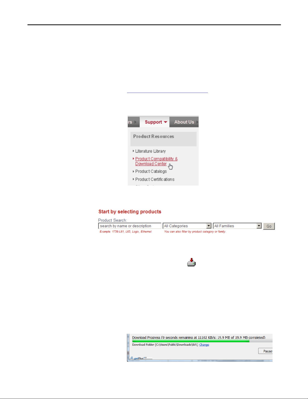
2. From the Support tab, choose Product Compatibility & Download
Center.
3. On the Get Downloads tab, click Find Product Downloads.
4. Enter the catalog number and click Go.
5. Select the module from the list then click the Find Downloads button at
the bottom of the Selections tab.
6. Click the download graphic .
The Available Downloads window opens.
7. From the bulleted list, choose the firmware name.
The End User License Agreement opens.
8. Review the agreement and click I Agree.
The Rockwell Automation Download Manager opens and the download
begins. The location of the downloaded file is shown under the progress
bar.
Rockwell Automation Publication ENET-IN002F-EN-P - January 2014 29
Page 30
Chapter 1 Install a 1756 EtherNet/IP Communication Module
9. When the downloaded is complete, click Close.
10. Locate the downloaded .zip file and extract it to a temporary directory.
11. Shut down any instances of the Logix Designer application that are
currently running.
12. In the temporary directory, double-click the MPSetup.exe file and follow
the onscreen instructions to install the AOP.
Connect to the Module via the USB Port
These 1756 EtherNet/IP communication modules have a USB device port:
• 1756-EN2F - ControlLogix EtherNet/IP Bridge module
• 1756-EN2T - ControlLogix EtherNet/IP Bridge module
• 1756-EN2TSC - ControlLogix EtherNet/IP Secure Communication
module
• 1756-EN2TR - ControlLogix EtherNet/IP 2-port module
• 1756-EN2TRXT - ControlLogix-XT EtherNet/IP 2-port module
• 1756-EN2TXT - ControlLogix-XT EtherNet/IP module
• 1756-EN3TR - ControlLogix EtherNet/IP 2-port module
WARNING: Do not use the USB port in hazardous locations.
ATTENTION: The USB port is intended for temporary local programming
purposes only and not intended for permanent connection. The USB cable is not
to exceed 3.0 m (9.84 ft) and must not contain hubs. The USB cable can be
ordered from Rockwell Automation, catalog number 9300-USBCBL-ABHR.
The module has a USB device port that uses a series B receptacle. To use the USB
port, you must have RSLinx Classic software, version 2.55 or later, installed on
your computer.
Use a USB cable to connect your computer to the USB port. You can download
programs to controllers and configure Ethernet modules directly from your
computer over a USB connection.
For more information about USB setup and configuration, see Chapter 5,
Communication on page 83.
30 Rockwell Automation Publication ENET-IN002F-EN-P - January 2014
USB
Page 31

Install a 1756 EtherNet/IP Communication Module Chapter 1
Download the Firmware
Complete these steps to download and install the firmware.
1. Go to the Rockwell Automation Web site at
http://www.rockwellautomation.com/.
2. From the Support tab, product Product Compatibility & Download
Center.
3. On the Get Downloads tab, click Find Product Downloads.
4. Enter your search criteria and click Go.
5. Select the module from the list then click the Find Downloads button at
the bottom of the Selections tab.
6. Click the download graphic .
The Available Downloads window opens.
7. From the bulleted list, choose the firmware name.
The End User License Agreement opens.
8. Review the agreement and click I Agree.
The Rockwell Automation Download Manager opens and the download
begins. The location of the downloaded file is shown under the progress
bar.
9. When the downloaded is complete, click Close.
10. Locate the downloaded .zip file and extract it to a temporary directory.
11. Use the ControlFlash utility to install the firmware.
Rockwell Automation Publication ENET-IN002F-EN-P - January 2014 31
Page 32

Chapter 1 Install a 1756 EtherNet/IP Communication Module
Digitally Signed Firmware
Digitally signed firmware provides an extra level of integrity at the firmware level.
The following modules are compatible with signed firmware, depending on the
firmware version:
• 1756-EN2F • 1756-EN2TRXT
• 1756-EN2T • 1756-EN2TXT
• 1756-EN2TSC • 1756-EN3TR
• 1756-EN2TR
Apply Chassis Power and Check Status Indicators
IMPORTANT
Installing signed firmware into your product will make it incompatible with
some versions of firmware. Once the upgrade is complete, your module will
accept only upgrade attempts that include signed firmware. Any unsigned
firmware updates will be rejected by the module.
Select the signed firmware file from the support website and download
(following the same steps on
module, the ControlFLASH
page 31). When installing the firmware into your
firmware update kit will give warnings that
proceeding will make your module incompatible with some versions of firmware.
To allow backward compatibility, modules ship with unsigned firmware installed
and must be upgraded by using this process to take advantage of this feature.
Before you apply power, you must install and connect a ControlLogix chassis and
power supply.
Follow these steps to apply power.
1. Flip the switch to the ON position.
32 Rockwell Automation Publication ENET-IN002F-EN-P - January 2014
32458
Page 33

Install a 1756 EtherNet/IP Communication Module Chapter 1
LINK
LINK
NET
OK
32452
NET
OK
1
LNK1
LNK2
NET
OK
LNK1
1
2
LNK2
NETOKOK
32452
LINK
NET
OK
2. Check the power supply and module status indicators and alphanumeric
display to determine that the power supply and module are operating
properly.
The alphanumeric display should cycle through the following states:
TEST - PASS - OK - REV x.x, where x.x is the module’s firmware revision.
The display then alternates between OK and port link status for both
ports.
This graphic shows the front of the module for these modules (extendedtemperature versions [catalog numbers 1756-EN2TXT and 1756EN2TRXT] not shown).
NET
OK
LINK
Install or Remove the Module Under Power
Single-port
Module
Single-port
Module
OK
LINK
NET
LINK
OK
NET
32452
LNK1
Dual-port
Module
LNK2
NET
OK
LNK1
LNK2
NET
Dual-port
Module
32452
You can install or remove this module while chassis power is applied.
WARNING: When you insert or remove the module while backplane power is
on, an electrical arc can occur. This could cause an explosion in hazardous
location installations.
Be sure that power is removed or the area is nonhazardous before proceeding.
Repeated electrical arcing causes excessive wear to contacts on both the module
and its mating connector. Worn contacts may create electrical resistance that can
affect module operation.
Rockwell Automation Publication ENET-IN002F-EN-P - January 2014 33
ATTENTION: Although the module is designed to support RIUP, when you
remove or insert the module with field-side power applied, unintended
machine motion or loss of process control can occur. Exercise extreme caution
when using this feature.
Page 34

Chapter 1 Install a 1756 EtherNet/IP Communication Module
Follow these steps to remove or replace the module.
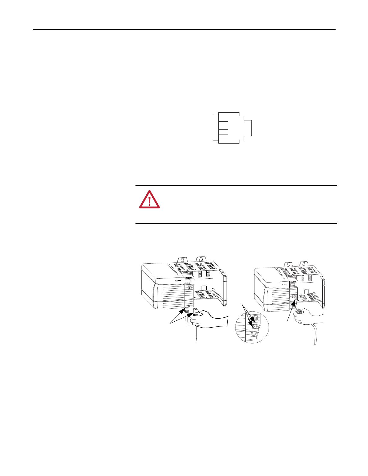
1. Push on the upper and lower module tabs to disengage them.
32460
2. Slide the module out of the chassis.
IMPORTANT
32461
If you want to replace an existing module with an identical one, and you want
to resume identical system operation, you must install the new module in the
same slot and assign the same network configuration.
34 Rockwell Automation Publication ENET-IN002F-EN-P - January 2014
Page 35

Chapter 2
Install a 1768 EtherNet/IP Communication
Module
Topic Page
Installation Summary 37
Set the Network IP Address 38
Install the Module 46
Wire the Module 48
Download the Add-on Profile 49
Download the Firmware 50
Apply Chassis Power and Check Status Indicators 51
Remove the Module 52
ATTENTION: Environment and Enclosure
This equipment is intended for use in a Pollution Degree 2 industrial environment, in overvoltage Category II applications (as defined
in IEC 60664-1), at altitudes up to 2000 m (6562 ft) without derating.
This equipment is not intended for use in residential environments and may not provide adequate protection to radio communication
services in such environments.
This equipment is supplied as open-type equipment. It must be mounted within an enclosure that is suitably designed for those
specific environmental conditions that will be present and appropriately designed to prevent personal injury resulting from
accessibility to live parts. The enclosure must have suitable flame-retardant properties to prevent or minimize the spread of flame,
complying with a flame spread rating of 5VA or be approved for the application if non-metallic. The interior of the enclosure must be
accessible only by the use of a tool. Subsequent sections of this publication may contain additional information regarding specific
enclosure type ratings that are required to comply with certain product safety certifications.
In addition to this publication, see the following:
• Industrial Automation Wiring and Grounding Guidelines, publication
• NEMA 250 and IEC 60529, as applicable, for explanations of the degrees of protection provided by enclosures
1770-4.1, for additional installation requirements
Rockwell Automation Publication ENET-IN002F-EN-P - January 2014 35
Page 36

Chapter 2 Install a 1768 EtherNet/IP Communication Module
North American Hazardous Location Approval
The following information applies when operating this
equipment in hazardous locations.
Products marked "CL I, DIV 2, GP A, B, C, D" are suitable for use in Class I
Division 2 Groups A, B, C, D, Hazardous Locations and nonhazardous
locations only. Each product is supplied with markings on the rating
nameplate indicating the hazardous location temperature code. When
combining products within a system, the most adverse temperature
code (lowest "T" number) may be used to help determine the overall
temperature code of the system. Combinations of equipment in your
system are subject to investigation by the local Authority Having
Jurisdiction at the time of installation.
WARNING: EXPLOSION HAZARD
• Do not disconnect equipment unless power has been
removed or the area is known to be nonhazardous.
• Do not disconnect connections to this equipment
unless power has been removed or the area is known
to be nonhazardous. Secure any external connections
that mate to this equipment by using screws, sliding
latches, threaded connectors, or other means
provided with this product.
• Substitution of components may impair suitability
for Class I, Division 2.
• If this product contains batteries, they must only be
changed in an area known to be nonhazardous.
Informations sur l’utilisation de cet équipement en
environnements dangereux.
Les produits marqués "CL I, DIV 2, GP A, B, C, D" ne conviennent qu'à une
utilisation en environnements de Classe I Division 2 Groupes A, B, C, D
dangereux et non dangereux. Chaque produit est livré avec des
marquages sur sa plaque d'identification qui indiquent le code de
température pour les environnements dangereux. Lorsque plusieurs
produits sont combinés dans un système, le code de température le plus
défavorable (code de température le plus faible) peut être utilisé pour
déterminer le code de température global du système. Les combinaisons
d'équipements dans le système sont sujettes à inspection par les
autorités locales qualifiées au moment de l'installation.
AVERTISSEMENT: RISQUE D’EXPLOSION
• Couper le courant ou s'assurer que l'environnement
est classé non dangereux avant de débrancher
l'équipement.
• Couper le courant ou s'assurer que l'environnement
est classé non dangereux avant de débrancher les
connecteurs. Fixer tous les connecteurs externes
reliés à cet équipement à l'aide de vis, loquets
coulissants, connecteurs filetés ou autres moyens
fournis avec ce produit.
• La substitution de composants peut rendre cet
équipement inadapté à une utilisation en
environnement de Classe I, Division 2.
• S'assurer que l'environnement est classé non
dangereux avant de changer les piles.
36 Rockwell Automation Publication ENET-IN002F-EN-P - January 2014
Page 37

Install a 1768 EtherNet/IP Communication Module Chapter 2
European Hazardous Location Approval
The following applies when the product bears the Ex Marking.
This equipment is intended for use in potentially explosive atmospheres as defined by European Union Directive 94/9/EC and has been found to comply with the
Essential Health and Safety Requirements relating to the design and construction of Category 3 equipment intended for use in Zone 2 potentially explosive
atmospheres, given in Annex II to this Directive.
Compliance with the Essential Health and Safety Requirements has been assured by compliance with EN 60079-15 and EN 60079-0.
ATTENTION: This equipment is not resistant to sunlight or other sources of UV radiation.
WARNING:
• This equipment shall be mounted in an ATEX certified enclosure with a minimum ingress protection rating of at least IP54 ( as
defined in IEC60529) and used in an environment of not more than Pollution Degree 2 (as defined in IEC 60664-1) when
applied in Zone 2 environments. The enclosure must utilize a tool removable cover or door.
• This equipment shall be used within its specified ratings defined by Rockwell Automation.
• Provision shall be made to prevent the rated voltage from being exceeded by transient disturbances of more than 140% of the
rated voltage when applied in Zone 2 environments.
• Secure any external connections that mate to this equipment by using screws, sliding latches, threaded connectors, or other
means provided with this product.
• Do not disconnect equipment unless power has been removed or the area is known to be nonhazardous.
ATTENTION: Prevent Electrostatic Discharge
This equipment is sensitive to electrostatic discharge, which can cause internal damage and affect normal operation. Follow these
guidelines when you handle this equipment:
• Touch a grounded object to discharge potential static.
• Wear an approved grounding wriststrap.
• Do not touch connectors or pins on component boards.
• Do not touch circuit components inside the equipment.
• Use a static-safe workstation, if available.
• Store the equipment in appropriate static-safe packaging when not in use.
Installation Summary
Follow these steps to install a communication module in a 1768 CompactLogix
system.
1.
Set the Network IP Address.
Install the Module.
2.
Connect the Module to an EtherNet/IP Network via an RJ45
3.
Connection.
Download the Add-on Profile.
4.
Download the Firmware. - Optional
5.
Apply Chassis Power and Check Status Indicators.
6.
Remove the Module. - Optional
7.
Rockwell Automation Publication ENET-IN002F-EN-P - January 2014 37
Page 38

Chapter 2 Install a 1768 EtherNet/IP Communication Module
Grounding Considerations
ATTENTION: This product is grounded through the DIN rail to chassis ground.
Use zinc-plated yellow-chromate steel DIN rail to assure proper grounding. The
use of other DIN rail materials (for example, aluminum or plastic) that can
corrode, oxidize, or are poor conductors, can result in improper or intermittent
grounding. Secure DIN rail to mounting surface approximately every 200 mm
(7.87 in.) and use end-anchors appropriately.
Set the Network IP Address
To operate an EtherNet/IP communication module on an EtherNet/IP network,
you must set a network IP address.
The IP address uniquely identifies the module. The IP address is in the form
xxx.xxx.xxx.xxx where each xxx is a number from 000…254.
There are some reserved values that you cannot use as the first octet in the
address. These numbers are examples of values you cannot use:
• 001.xxx.xxx.xxx
• 127.xxx.xxx.xxx
• 223 to 255.xxx.xxx.xxx
The specific reserved values that cannot be used vary by application.
For more information about configuring an EtherNet/IP network, see
EtherNet/IP Network Configuration User Manual, publication
You can use these tools to set the network Internet Protocol (IP) address on your
1768 EtherNet/IP communication module:
• Bootstrap Protocol (BOOTP)/Dynamic Host Configuration Protocol
(DHCP) server
ENET-UM001.
• RSLinx Classic software
• the Studio 5000 environemnt
The module uses these tools sequentially to set the IP address.
The 1768 EtherNet/IP communication modules are shipped with BOOTP/
DHCP enabled.
38 Rockwell Automation Publication ENET-IN002F-EN-P - January 2014
Page 39

Install a 1768 EtherNet/IP Communication Module Chapter 2
This graphic shows the process used to set your module’s IP address.
Figure 2 - How Your Module’s IP Address is Set
Module Powerup
Is DHCP or
BOOTP
enabled?
Adapter uses IP address
stored in nonvolatile
memory.
YesNo
Module requests
address from DHCP/
BOOTP server.
Module has an IP
address.
If you need to reset your module’s settings to factory default settings during
normal module operation, see
Reset the Module IP Address to a Factory Default
Value on page 46.
These tools are used in this sequence to set the network IP address.
1.
Set the Network IP Address with a BOOTP/DHCP Server.
Set the Network IP Address with RSLinx Software or the Studio 5000
2.
Environment.
Rockwell Automation Publication ENET-IN002F-EN-P - January 2014 39
Page 40

Chapter 2 Install a 1768 EtherNet/IP Communication Module
Set the Network IP Address with a BOOTP/DHCP Server
The BOOTP/DHCP server is a standalone server you can use to set an IP
address. When used, the BOOTP/DHCP server sets an IP address and other
Transport Control Protocol (TCP) parameters.
Access the BOOTP/DHCP server from one of these locations:
• Programs > Rockwell Software > BOOTP-DHCP Server
If you have not installed the server, you can download and install it from
http://www.ab.com/networks/ethernet/bootp.html.
• Tools directory on the Studio 5000 environemnt installation CD
IMPORTANT
Before you start the BOOTP/DHCP server, make sure you have the
module’s hardware (MAC) address. The hardware address is on a sticker
on the side of the communication module and uses an address in a
format similar to the following:
00-00-BC-14-55-35
Follow these steps to set the module’s IP address with a BOOTP/DHCP server.
1. Start the BOOTP/DHCP software.
2. From the Tools menu, choose Network Settings.
3. Type the Subnet Mask of the network.
The Gateway address, Primary and/or Secondary DNS address, and
Domain Name fields are optional.
4. Click OK.
The Request History panel appears with the hardware addresses of all
modules issuing BOOTP requests.
40 Rockwell Automation Publication ENET-IN002F-EN-P - January 2014
Page 41

5. Select the appropriate module.
6. Click Add to Relation List.
The New Entry dialog box appears.
Install a 1768 EtherNet/IP Communication Module Chapter 2
7. Type an IP Address, Hostname, and Description for the module.
8. Click OK.
9. To permanently assign this configuration to the module, wait for the
module to appear in the Relation List panel and select it.
10. Click Disable BOOTP/DHCP.
When power is recycled, the module uses the assigned configuration and
does not issue a BOOTP request.
IMPORTANT
If you do not click Disable BOOTP/DHCP, on a power cycle, the host
controller clears the current IP configuration and begins sending
BOOTP requests again.
Rockwell Automation Publication ENET-IN002F-EN-P - January 2014 41
Page 42

Chapter 2 Install a 1768 EtherNet/IP Communication Module
Use DHCP Software
Dynamic Host Configuration Protocol (DHCP) software automatically assigns
IP addresses to client stations logging onto a TCP/IP network. DHCP is based
on BOOTP and maintains some backward compatibility. The main difference is
that BOOTP allows for manual configuration (static), while DHCP allows for
both static and dynamic allocation of network addresses and configurations to
newly attached modules.
Be cautious when using DHCP software to configure a module. A BOOTP
client, such as the EtherNet/IP communication modules, can start from a DHCP
server only if the DHCP server is specifically written to also handle BOOTP
queries. This is specific to the DHCP software package used. Consult your
system administrator to see if a DHCP package supports BOOTP commands
and manual IP allocation.
ATTENTION: The EtherNet/IP communication module must be assigned a
fixed network address. The IP address of this module must not be dynamically
provided.
Failure to observe this precaution may result in unintended machine motion or
loss of process control.
Set the Network IP Address with RSLinx Software or the Studio 5000 Environment
This table describes when to set the network IP address with RSLinx or
RSLogix 5000 software.
Conditions Software to Use Page
• A BOOTP server is not available.
• The EtherNet/IP communication module is connected to another
NetLinx network.
The Studio 5000 project is online with a controller that communicates to or
through the EtherNet/IP communication module.
Consider these factors when you determine how to set the network IP address:
• Network isolation from or integration into the plant/enterprise network
• Network size - For large networks, isolated networks, it might be more
convenient and safer to use a BOOTP/DHCP server rather than
the Studio 5000 environment or RSLinx software. The BOOTP/DHCP
server also limits the possibility of assigning duplicate IP addresses.
• Company policies and procedures dealing with plant floor network
installation and maintenance
RSLinx 43
Studio 5000 environment
(Logix Designer application)
45
• Level of involvement by IT personnel in plant-floor network installation
and maintenance
• Type of training offered to control engineers and maintenance personnel
42 Rockwell Automation Publication ENET-IN002F-EN-P - January 2014
Page 43

Install a 1768 EtherNet/IP Communication Module Chapter 2
If you use the Rockwell Automation BOOTP or DHCP server in an uplinked
subnet where an enterprise DHCP server exists, a module may get an address
from the enterprise server before the Rockwell Automation utility even sees the
module. You might have to disconnect from the uplink to set the address and
configure the module to retain its static address before reconnecting to the
uplink. This is not a problem if you have node names configured in the module
and leave DHCP enabled.
Set the Network IP Address with RSLinx Software
Follow these steps to use RSLinx software to set the communication module’s
IP address.
1. From the Communications menu, choose RSWho.
The RSWho dialog box appears.
2. Navigate to the Ethernet network.
3. Right-click the EtherNet/IP module and choose Module Configuration.
The Module Configuration dialog box appears.
4. Click the Port Configuration tab.
Rockwell Automation Publication ENET-IN002F-EN-P - January 2014 43
Page 44

Chapter 2 Install a 1768 EtherNet/IP Communication Module
5. For Network Configuration Type, click Static to permanently assign this
configuration to the port.
IMPORTANT
If you click Dynamic, on a power cycle, the controller clears the
current IP configuration and resumes sending BOOTP requests.
6. Type this information in the appropriate fields:
• In the IP Address field, type the IP address.
• In the Network Mask field, type the network mask address.
• In the Gateway Address field, type the gateway address.
• In the Primary Name Server field, type the IP address.
• In the Secondary Name Server field, type the IP address.
• In the Domain Name field, type the domain name.
• In the Host Name field, type the host name.
7. Configure the port settings.
To Then
Use the default port speed and
duplex settings
Manually configure your port’s
speed and duplex settings
Leave Auto-negotiate port speed and duplex checked.
This setting determines the actual speed and duplex setting.
Follow these steps.
1. Clear the Auto-negotiate port speed and duplex checkbox.
2. From the Current Port Speed pull-down menu, choose a port
speed.
8. Click OK.
3. From the Current Duplex pull-down menu, choose the appropriate
Duplex value, that is, Half Duplex or Full Duplex.
44 Rockwell Automation Publication ENET-IN002F-EN-P - January 2014
Page 45

Install a 1768 EtherNet/IP Communication Module Chapter 2
Set the Network IP Address with the Studio 5000 Environment
Follow these steps to use the Logix Designer application from the Studio 5000
environment to set the communication module’s IP address.
1. In the Controller Organizer, right-click the EtherNet/IP module and
choose Properties.
The Module Properties dialog box appears.
2. Click the Port Configuration tab.
3. In the IP Address field, type the IP address.
4. In the other fields, type the other network parameters, if needed.
IMPORTANT
The fields that appear vary between EtherNet/IP communication
modules.
5. Click Apply.
6. Click OK.
Rockwell Automation Publication ENET-IN002F-EN-P - January 2014 45
Page 46

Chapter 2 Install a 1768 EtherNet/IP Communication Module
Reset the Module IP Address to a Factory Default Value
You can reset the module’s IP address to its factory default value by sending a
MSG instruction to the module.
For more information on resetting the network IP address to its default value
with a MSG instruction, see Knowledgebase Answer ID 55362, Reset module to
factory defaults. You can access the article at
http://rockwellautomation.custhelp.com/app/answers/list.
Install the Module
Follow these steps to install the module.
Mount the Module with Screws
IMPORTANT
Complete these steps to install the module with screws.
1. Use the modules as a template and mark pilot holes on your panel.
2. Drill the pilot holes for M4 or #8 screws.
3. Use M4 or #8 screws to mount the modules to your panel, by using
1.16 N•m (10 lb•in) of torque.
4. Ground the module on a ground bus with a dedicated earth ground stake.
5. Connect the ground bus to a functional earth ground on the DIN rail
or panel.
Refer to Industrial Automation Wiring and Grounding Guidelines, publication
1770-4.1, for additional information.
Do not use screws and DIN rail to mount the modules. It is possible to break
the mounting tabs off if you screw the modules to the panel while they are on
the DIN rail.
46 Rockwell Automation Publication ENET-IN002F-EN-P - January 2014
Page 47

Install a 1768 EtherNet/IP Communication Module Chapter 2
Mount on a DIN Rail
Follow these steps to install the module on a DIN rail.
1. Mount the DIN rail in a suitable location.
ATTENTION: This product is grounded through the DIN rail to chassis
ground. Use zinc-plated yellow-chromate steel DIN rail to assure proper
grounding. The use of other DIN rail materials (for example, aluminum
or plastic) that can corrode, oxidize, or are poor conductors, can result in
improper or intermittent grounding. Secure DIN rail to mounting
surface approximately every 200 mm (7.87 in.) and use end-anchors
appropriately.
2. Open the DIN rail latches on the module.
31597-M
3. Align and press the module onto the DIN rail to the left of the controller.
4. Slide the module snugly against the controller.
Rockwell Automation Publication ENET-IN002F-EN-P - January 2014 47
Page 48

Chapter 2 Install a 1768 EtherNet/IP Communication Module
In this example, the 1768 EtherNet/IP communication module is installed in
slot 1 and the 1768 CompactLogix controller is installed in slot 0.
5. Mount the 1768 power supply and additional 1768 modules to the left of
the controller.
6. Close the DIN rail latches.
31599-M
Wire the Module
Use the following information to wire the module.
Connect the Module to an EtherNet/IP Network via an RJ45 Connection
Wire the RJ45 connector as shown.
8 ------ NC
7 ------ NC
6 ------ RD5 ------ NC
4 ------ NC
3 ------ RD+
2 ------ TD1 ------ TD+
Follow these steps to connect the module to the network.
WARNING: If you connect or disconnect the communication cable with power
applied to this module or any device on the network, an electrical arc can
occur. This could cause an explosion in hazardous location installations.
Be sure that power is removed or the area is nonhazardous before proceeding.
48 Rockwell Automation Publication ENET-IN002F-EN-P - January 2014
Page 49

Install a 1768 EtherNet/IP Communication Module Chapter 2
1. Attach the cable with the RJ45 connector to the Ethernet port on the
bottom of the module as shown.
2. Attach the other end of the cable to the devices in your network.
Download the Add-on Profile
If a module has a later firmware revision for the communication module than
recognized in the most current version of the Logix Designer application, you
need to download the Add-on Profile (AOP) for the communication module so
it can be recognized in the Controller Organizer.
Complete these steps to download and install an AOP.
1. Go to the Rockwell Automation Web site at
http://www.rockwellautomation.com/.
2. From the Support tab, choose Product Compatibility & Download
Center.
3. On the Get Downloads tab, click Find Product Downloads.
4. Enter the catalog number and click Go.
5. Select the module from the list then click the Find Downloads button at
the bottom of the Selections tab.
Rockwell Automation Publication ENET-IN002F-EN-P - January 2014 49
Page 50

Chapter 2 Install a 1768 EtherNet/IP Communication Module
6. Click the download graphic .
The Available Downloads window opens.
7. From the bulleted list, choose the firmware name.
The End User License Agreement opens.
8. Review the agreement and click I Agree.
The Rockwell Automation Download Manager opens and the download
begins. The location of the downloaded file is shown under the progress
bar.
9. When the downloaded is complete, click Close.
10. Locate the downloaded .zip file and extract it to a temporary directory.
Download the Firmware
11. Shut down any instances of the Logix Designer application that are
currently running.
12. In the temporary directory, double-click the MPSetup.exe file and follow
the onscreen instructions to install the AOP.
Complete these steps to download and install the firmware.
1. Go to the Rockwell Automation Web site at
http://www.rockwellautomation.com/.
2. From the Support tab, product Product Compatibility & Download
Center.
3. On the Get Downloads tab, click Find Product Downloads.
4. Enter your search criteria and click Go.
5. Select the module from the list then click the Find Downloads button at
the bottom of the Selections tab.
50 Rockwell Automation Publication ENET-IN002F-EN-P - January 2014
Page 51

Install a 1768 EtherNet/IP Communication Module Chapter 2
6. Click the download graphic .
The Available Downloads window opens.
7. From the bulleted list, choose the firmware name.
The End User License Agreement opens.
8. Review the agreement and click I Agree.
The Rockwell Automation Download Manager opens and the download
begins. The location of the downloaded file is shown under the progress
bar.
9. When the downloaded is complete, click Close.
10. Locate the downloaded .zip file and extract it to a temporary directory.
Apply Chassis Power and Check Status Indicators
11. Use the ControlFlash utility to install the firmware.
Before you apply power, you must install and mount a CompactLogix controller
and Compact I/O™ power supply on the DIN rail.
Follow these steps to apply power.
1. Flip the switch to the ON position.
Rockwell Automation Publication ENET-IN002F-EN-P - January 2014 51
Page 52

Chapter 2 Install a 1768 EtherNet/IP Communication Module
2. Check the power supply (1) and module (2) status indicators and
alphanumeric display to determine that the power supply and module
are operating properly.
Remove the Module
1
2
Follow these steps to remove the communication module.
IMPORTANT
When you turn the CompactLogix power supply off, make sure you wait for all
status indicators on the power supply and controller to turn off before
disconnecting any part from the system.
If you disconnect the CompactLogix system while the controller is still writing
its program to memory, the program write will not be completed and you will
lose your program.
1. Flip the switch to the OFF position.
52 Rockwell Automation Publication ENET-IN002F-EN-P - January 2014
Page 53

Install a 1768 EtherNet/IP Communication Module Chapter 2
2. Open the DIN rail latches of the communication module and the module
directly to the left of communication module.
3. Slide the communication module and other modules to the right.
4. Open the DIN rail latches of the controller.
Rockwell Automation Publication ENET-IN002F-EN-P - January 2014 53
Page 54

Chapter 2 Install a 1768 EtherNet/IP Communication Module
5. Slide the controller and other modules away from the communication
module.
6. Pull the communication module off the DIN rail.
54 Rockwell Automation Publication ENET-IN002F-EN-P - January 2014
Page 55

Install a 1769 EtherNet/IP Adapter
Topic Page
System Configuration 57
Installation Summary 59
Set the Network IP Address 59
Install the Adapter in a 1769 System 68
Wire the Adapter 72
Download the Add-on Profile 74
Download the Firmware 75
Enable the Web Pages 76
Remove or Replace the Adapter 77
Chapter 3
ATTENTION: Environment and Enclosure
This equipment is intended for use in a Pollution Degree 2 industrial environment, in overvoltage Category II applications (as defined
in IEC 60664-1), at altitudes up to 2000 m (6562 ft) without derating.
This equipment is not intended for use in residential environments and may not provide adequate protection to radio communication
services in such environments.
This equipment is supplied as open-type equipment. It must be mounted within an enclosure that is suitably designed for those
specific environmental conditions that will be present and appropriately designed to prevent personal injury resulting from
accessibility to live parts. The enclosure must have suitable flame-retardant properties to prevent or minimize the spread of flame,
complying with a flame spread rating of 5VA or be approved for the application if nonmetallic. The interior of the enclosure must be
accessible only by the use of a tool. Subsequent sections of this publication may contain additional information regarding specific
enclosure type ratings that are required to comply with certain product safety certifications.
In addition to this publication, see the following:
• Industrial Automation Wiring and Grounding Guidelines, publication
1770-4.1, for additional installation requirements.
• NEMA 250 and IEC 60529, as applicable, for explanations of the degrees of protection provided by enclosures.
Rockwell Automation Publication ENET-IN002F-EN-P - January 2014 55
Page 56

Chapter 3 Install a 1769 EtherNet/IP Adapter
North American Hazardous Location Approval
The following information applies when operating this equipment in
hazardous locations.
Products marked "CL I, DIV 2, GP A, B, C, D" are suitable for use in Class I
Division 2 Groups A, B, C, D, Hazardous Locations and nonhazardous
locations only. Each product is supplied with markings on the rating
nameplate indicating the hazardous location temperature code. When
combining products within a system, the most adverse temperature
code (lowest "T" number) may be used to help determine the overall
temperature code of the system. Combinations of equipment in your
system are subject to investigation by the local Authority Having
Jurisdiction at the time of installation.
WARNING: EXPLOSION HAZARD
• Do not disconnect equipment unless power has been
removed or the area is known to be nonhazardous.
• Do not disconnect connections to this equipment
unless power has been removed or the area is known
to be nonhazardous. Secure any external connections
that mate to this equipment by using screws, sliding
latches, threaded connectors, or other means
provided with this product.
• Substitution of components may impair suitability
for Class I, Division 2.
• If this product contains batteries, they must only be
changed in an area known to be nonhazardous.
Informations sur l’utilisation de cet équipement en environnements
dangereux.
Les produits marqués "CL I, DIV 2, GP A, B, C, D" ne conviennent qu'à une
utilisation en environnements de Classe I Division 2 Groupes A, B, C, D
dangereux et non dangereux. Chaque produit est livré avec des
marquages sur sa plaque d'identification qui indiquent le code de
température pour les environnements dangereux. Lorsque plusieurs
produits sont combinés dans un système, le code de température le plus
défavorable (code de température le plus faible) peut être utilisé pour
déterminer le code de température global du système. Les combinaisons
d'équipements dans le système sont sujettes à inspection par les
autorités locales qualifiées au moment de l'installation.
WARNING: RISQUE D’EXPLOSION
• Couper le courant ou s'assurer que l'environnement
est classé non dangereux avant de débrancher
l'équipement.
• Couper le courant ou s'assurer que l'environnement
est classé non dangereux avant de débrancher les
connecteurs. Fixer tous les connecteurs externes
reliés à cet équipement à l'aide de vis, loquets
coulissants, connecteurs filetés ou autres moyens
fournis avec ce produit.
• La substitution de composants peut rendre cet
équipement inadapté à une utilisation en
environnement de Classe I, Division 2.
• S'assurer que l'environnement est classé non
dangereux avant de changer les piles.
ATTENTION: Prevent Electrostatic Discharge
This equipment is sensitive to electrostatic discharge, which can cause internal damage and affect normal operation. Follow these
guidelines when you handle this equipment:
• Touch a grounded object to discharge potential static.
• Wear an approved grounding wriststrap.
• Do not touch connectors or pins on component boards.
• Do not touch circuit components inside the equipment.
• Use a static-safe workstation, if available.
• Store the equipment in appropriate static-safe packaging when not in use.
WARNING: When used in a Class I, Division 2, hazardous location, this equipment must be mounted in a suitable enclosure with
proper wiring method that complies with the governing electrical codes.
56 Rockwell Automation Publication ENET-IN002F-EN-P - January 2014
Page 57

Install a 1769 EtherNet/IP Adapter Chapter 3
System Configuration
Follow these rules when planning your system configuration.
• The adapter must be the first and left-most module in the system (the first
module of Bank 1). Refer to page
• The adapter can communicate with up to 30 modules in a system
distributed across three I/O banks.
• An end cap/terminator must be on the last I/O bank.
• Each bank of I/O must have its own power supply.
• A bank of I/O can have a maximum of 16 modules with a maximum of
eight on either side of the power supply, depending upon module loading
on the supply.
• A 1769 I/O power supply has limits in the amount of 5V DC and
24V DC current it can supply to the modules in its I/O bank. These limits
depend on the catalog number (for example, 1769-PA2) of the supply. A
bank of modules should not exceed the current limits of the I/O bank
power supply. Refer to the Compact 1769 Expansion I/O Power Supplies
Installation Instructions, publication
• The maximum amount of current the system supports in one direction
(either side of the power supply) is: 2A @ 5V DC, 1A @ 24V DC.
• If another bank of I/O is required due to module requirements or I/O
loading, you can use a cable to link them together. You can have a
maximum of three banks of I/O connected with up to two
communication cables.
• Each module type has its own distance rating (the number of modules
from the power supply). Each module must be within this rating for its
type.
• The adapter has a distance rating of five, therefore the adapter must be
within five modules of the power supply.
58 for an example configuration.
1769-IN028.
Rockwell Automation Publication ENET-IN002F-EN-P - January 2014 57
Page 58

Chapter 3 Install a 1769 EtherNet/IP Adapter
Example Configurations
The following illustrations show examples of two valid system setups.
Bank 1
1769 I/O
1769-AENTR
1769 I/O
1769 Power Supply
1769 I/O
1769 I/O
1769 I/O
1769 I/O
1769-CRRx
I/O Slot Number
Left-to-Left Cable
I/O Slot Number
I/O Slot Number
I/O Slot Number
12
34 5
6
Right-to-Right Cable
Bank 2
1769 Power Supply
1769 I/O
1769 I/O
1769-CRRx
1769 I/O
1769-CLLx
1769 I/O
1769 I/O
10 11 12
987
1769 I/O
Bank 3
1769 I/O
1769 I/O
1769 Power Supply
1769 I/O
1769 I/O
1769 I/O
1769 I/O
1769 Right End Cap
20
19181716151413
1769 I/O
1769-CLLx
1769 I/O
Bank 3Bank 2Bank 1
1769 I/O
1769-AENTR
1769 I/O
1769-CRLx
1769 Power Supply
1769 I/O
1769-CRLx
1769 Power Supply
1769 I/O
1769-CRLx
1769 I/O
1769-CRLx
12 3 4 5 6
Right-to-Left Cable Right-to-Left Cable
1769 Power Supply
1769 I/O
1769 Right End Cap
42131
TIP
I/O modules are not required between either the adapter and an end cap
or between the power supply and an end cap.
58 Rockwell Automation Publication ENET-IN002F-EN-P - January 2014
Page 59

Install a 1769 EtherNet/IP Adapter Chapter 3
Installation Summary
Complete these steps to install an adapter in a 1769 CompactLogix system.
Set the Network IP Address.
1.
Install the Adapter in a 1769 System.
2.
Wire the Adapter.
3.
Download the Add-on Profile.
4.
Download the Firmware. - Optional
5.
Remove or Replace the Adapter. - Optional
6.
Grounding Considerations
ATTENTION: This product is grounded through the DIN rail to chassis ground.
Use zinc plated yellow-chromate steel DIN rail to assure proper grounding. The
use of other DIN rail materials (for example, aluminum or plastic) that can
corrode, oxidize, or are poor conductors, can result in improper or intermittent
grounding. Secure DIN rail to mounting surface approximately every 200 mm
(7.8 in.) and use end-anchors appropriately.
Set the Network IP Address
To operate an EtherNet/IP adapter on an EtherNet/IP network, you must set a
network IP address.
The IP address uniquely identifies the module. The IP address is in the form
xxx.xxx.xxx.xxx where each xxx is a number from 000…254.
There are some reserved values that you cannot use as the first octet in the
address. These numbers are examples of values you cannot use:
• 001.xxx.xxx.xxx
• 127.xxx.xxx.xxx
• 223 to 255.xxx.xxx.xxx
The specific reserved values that cannot be used vary by application.
For more information about configuring an EtherNet/IP network, see
EtherNet/IP Network Configuration User Manual, publication
ENET-UM001.
Rockwell Automation Publication ENET-IN002F-EN-P - January 2014 59
Page 60

Chapter 3 Install a 1769 EtherNet/IP Adapter
You can use these tools to set the network Internet Protocol (IP) address on your
1769 EtherNet/IP adapter:
• Bootstrap Protocol (BOOTP)/Dynamic Host Configuration Protocol
(DHCP) server - available out-of box
• RSLinx Classic software - only available for previously-configured
adapters
• Studio 5000 Logix Designer application, version 20.00.00 or later only available for previously-configured adapters
The module uses these tools sequentially to set the IP address.
The 1769 EtherNet/IP adapters are shipped with BOOTP/DHCP enabled.
This graphic shows the process used to set your module’s IP address.
Figure 3 - How Your Module’s IP Address is Set
Module uses IP address
stored in nonvolatile
memory.
Module Powerup
Is DHCP or
BOOTP
enabled?
Switches set
from
001…254?
YesNo
Module requests
address from DHCP/
BOOTP server.
Module has an IP address.
YesNo
If you need to reset your module’s settings to its factory default settings during
normal module operation, see
Reset the IP Address to a Factory Default Value on
page 67.
60 Rockwell Automation Publication ENET-IN002F-EN-P - January 2014
Page 61

Install a 1769 EtherNet/IP Adapter Chapter 3
These tools are used in this sequence to set the network IP address.
Set the Network IP Address with the Rotary Switches.
1.
Set the Network IP Address with a BOOTP/DHCP Server.
2.
Set the Network IP Address with RSLinx or the Studio 5000
3.
Environment.
Set the Network IP Address with the Rotary Switches
This graphic shows the rotary switches on the front the adpater.
X 100
X 10
X 1
At powerup, the adapter reads the rotary switches to determine if they are set to a
valid number for the last portion of the IP address, that is, if the numbers are in
the range from 001…254.
If the settings are a valid number, these conditions result:
• IP address = 192.168.1.xxx (where xxx represents the switch settings)
• Subnet mask = 255.255.255.0
• Gateway address = 192.168.1.1
• The module does not have a host name assigned, nor does it use any
Domain Name System
We recommend that you set the rotary switches to a valid number before
installing the module.
WARNING: When you change switch settings while power is on, an electrical
arc can occur. This could cause an explosion in hazardous location installations.
Be sure that power is removed or the area is nonhazardous before proceeding.
The module attempts to use the BOOTP/DHCP server to set the IP address if
the rotary switches are not set to a valid number.
Rockwell Automation Publication ENET-IN002F-EN-P - January 2014 61
Page 62

Chapter 3 Install a 1769 EtherNet/IP Adapter
Set the Network IP Address with a BOOTP/DHCP Server
The BOOTP/DHCP server is a standalone server you can use to set an IP
address. When used, the BOOTP/DHCP server sets an IP address and other
Transport Control Protocol (TCP) parameters.
Access the BOOTP/DHCP server from one of these locations:
• Programs > Rockwell Software > BOOTP-DHCP Server
If you have not installed the server, you can download and install it from
http://www.ab.com/networks/ethernet/bootp.html.
• Tools directory on the Studio 5000 environment installation CD
IMPORTANT
Before you start the BOOTP/DHCP server, make sure you have the
module’s hardware (MAC) address. The hardware address is on a sticker
on the side of the adapter and uses an address in a format similar to the
following:
00-00-BC-14-55-35
Complete these steps to set the module’s IP address with a BOOTP/DHCP
server.
1. Start the BOOTP/DHCP software.
2. From the Tools menu, choose Network Settings.
3. Type the Subnet Mask of the network.
The Gateway address, Primary and/or Secondary DNS address, and
Domain Name fields are optional.
4. Click OK.
The Request History panel appears with the hardware addresses of all
modules issuing BOOTP requests.
62 Rockwell Automation Publication ENET-IN002F-EN-P - January 2014
Page 63

5. Select the appropriate module.
6. Click Add to Relation List.
The New Entry dialog box appears.
Install a 1769 EtherNet/IP Adapter Chapter 3
7. Type an IP Address, Hostname, and Description for the module.
8. Click OK.
9. To permanently assign this configuration to the module, wait for the
module to appear in the Relation List panel and select it.
10. Click Disable BOOTP/DHCP.
When power is recycled, the module uses the assigned configuration and
does not issue a BOOTP request.
IMPORTANT
If you do not click Disable BOOTP/DHCP, when power is cycled, the host
controller clears the current IP configuration and begins sending
BOOTP requests again.
Rockwell Automation Publication ENET-IN002F-EN-P - January 2014 63
Page 64

Chapter 3 Install a 1769 EtherNet/IP Adapter
Use DHCP Software
Dynamic Host Configuration Protocol (DHCP) software automatically assigns
IP addresses to client stations logging onto a TCP/IP network. DHCP is based
on BOOTP and maintains some backward compatibility. The main difference is
that BOOTP allows for manual configuration (static), while DHCP allows for
both static and dynamic allocation of network addresses and configurations to
newly attached modules.
Be cautious when using DHCP software to configure a module. A BOOTP
client, such as the EtherNet/IP adapters, can start from a DHCP server only if
the DHCP server is specifically written to also handle BOOTP queries. This is
specific to the DHCP software package used. Consult your system administrator
to see if a DHCP package supports BOOTP commands and manual IP
allocation.
ATTENTION: The EtherNet/IP adapter module must be assigned a fixed
network address. The IP address of this module must not be dynamically
provided.
Failure to observe this precaution can result in unintended machine motion or
loss of process control.
Set the Network IP Address with RSLinx or the Studio 5000 Environment
This table describes when to set the network IP address with RSLinx or the
Studio 5000 environment.
Conditions Software to Use Page
• A BOOTP server is not available.
• The EtherNet/IP adapter is connected to another NetLinx network.
The Logix Designer project is online with a controller that communicates to
or through the EtherNet/IP adapter.
Consider these factors when you determine how to set the network IP address:
• Network isolation from or integration into the plant/enterprise network
• Network size - For large networks, isolated networks, it might be more
convenient and safer to use a BOOTP/DHCP server rather than
the Logix Designer application or RSLinx software. The BOOTP/DHCP
server also limits the possibility of assigning duplicate IP addresses.
• Company policies and procedures dealing with plant floor network
installation and maintenance
• Level of involvement by IT personnel in plant-floor network installation
and maintenance
• Type of training offered to control engineers and maintenance personnel
RSLinx software 65
Studio 5000 environment
(Logix Designer application,
version 20.00.00 or later)
67
64 Rockwell Automation Publication ENET-IN002F-EN-P - January 2014
Page 65

Install a 1769 EtherNet/IP Adapter Chapter 3
If you use the Rockwell Automation BOOTP or DHCP server in an uplinked
subnet where an enterprise DHCP server exists, a module can get an address
from the enterprise server before the Rockwell Automation utility even sees the
module. In this case, disconnect from the uplink to set the address and configure
the module to retain its static address before reconnecting to the uplink. This is
not a problem if you have node names configured in the module and leave
DHCP enabled.
Set the Network IP Address with RSLinx Software
Complete these steps to use RSLinx software to set the adapter’s IP address.
1. From the Communications menu, choose RSWho.
The RSWho dialog box appears.
2. Navigate to the Ethernet network.
IMPORTANT
If there is a yellow question mark next to adapter (it is unrecognized),
complete these steps.
1. Right-click the adapter and select Upload EDS File from Device.
2. Follow the on-screen prompts to upload the file.
The adapter is recognized and the yellow question mark is removed.
3. Right-click the EtherNet/IP module and choose Module Configuration.
The Module Configuration dialog box appears.
Rockwell Automation Publication ENET-IN002F-EN-P - January 2014 65
Page 66

Chapter 3 Install a 1769 EtherNet/IP Adapter
4. Click the Port Configuration tab.
5. For Network Configuration Type, click Static to permanently assign this
configuration to the port.
IMPORTANT
If you click Dynamic, on a power cycle, the controller clears the
current IP configuration and resumes sending BOOTP requests.
6. Type this information in the appropriate fields:
• In the IP Address field, type the IP address.
• In the Network Mask field, type the network mask address.
• In the Gateway Address field, type the gateway address.
• In the Primary Name Server field, type the IP address.
• In the Secondary Name Server field, type the IP address.
• In the Domain Name field, type the domain name.
• In the Host Name field, type the host name.
7. Configure the port settings.
To Then
Use the default port speed and
duplex settings
Manually configure your port’s
speed and duplex settings
Leave Auto-negotiate port speed and duplex checked.
This setting determines the actual speed and duplex setting.
Follow these steps.
1. Clear the Auto-negotiate port speed and duplex checkbox.
2. From the Current Port Speed pull-down menu, choose a port
speed.
3. From the Current Duplex pull-down menu, choose the appropriate
Duplex value, that is, Half Duplex or Full Duplex.
8. Click OK.
66 Rockwell Automation Publication ENET-IN002F-EN-P - January 2014
Page 67

Install a 1769 EtherNet/IP Adapter Chapter 3
Set the Network IP Address with the Studio 5000 Environment
Complete these steps to use the Logix Designer application to set the adapter’s IP
address.
1. In the Controller Organizer, right-click the EtherNet/IP module and
choose Properties.
The Module Properties dialog box appears.
2. Click the Port Configuration tab.
3. In the IP Address field, type the IP address.
4. In the other fields, type the other network parameters, if needed.
5. Click Apply.
6. Click OK.
Reset the IP Address to a Factory Default Value
You can reset the adapter’s IP address to its factory default value by sending a
MSG instruction to the module.
For more information on resetting the network IP address to its default value
with a MSG instruction, see Knowledgebase Answer ID 55362, at
https://rockwellautomation.custhelp.com/app/answers/detail/a_id/55362
(login required).
Rockwell Automation Publication ENET-IN002F-EN-P - January 2014 67
Page 68

Chapter 3 Install a 1769 EtherNet/IP Adapter
Install the Adapter in a 1769 System
Use the following information to install the adapter with the 1769 system.
Adapter Description
7b
MOD
LINK 1
NET
LINK 2
Comm Adapter
X 100
X 10
X 1
5
LINK 1LINK 2
6a
8
1
2
3
4
9
7a
6b
Item Description
1 Status indicators
2 IP address rotary switches
3 Ethernet port
4 Ethernet port for use in a device-level ring network
5 Nameplate label
6 Upper panel mounting tab
Lower panel mounting tab
7 Upper DIN-rail latch
Lower DIN-rail latch
8 Bus lever
9 Stationary bus connector with male pins
46269
68 Rockwell Automation Publication ENET-IN002F-EN-P - January 2014
Page 69

Install a 1769 EtherNet/IP Adapter Chapter 3
System Assembly
The adapter can be attached to adjacent 1769 modules before or after mounting.
IMPORTANT
The 1769-AENTR adapter must be used with one of the following Rockwell
Automation power supply models: 1769-PA2, 1769-PB2, 1769-PA4, or
1769-PB4.
For mounting instructions, see
Mount the Adapter with Screws on page 70, or
Mount on a DIN Rail on page 71.
Follow these steps to assemble the Compact I/O™ system.
a
b
a
1769-
a
a
d
1. Disconnect power.
WARNING: If you insert or remove the module while backplane power is on, an
electrical arc can occur. This could cause an explosion in hazardous location
installations.
Be sure that power is removed before proceeding.
c
e
42126
2. Check that the bus lever of the module to the right of the adapter is in the
unlocked (fully right) position.
3. Use the upper and lower tongue-and-groove slots (a) to secure the modules
together.
4. Move the module back along the tongue-and-groove slots until the bus
connectors line up with each other.
5. Use your fingers or a small screwdriver to push the bus lever of the module
to the right of the adapter back slightly toclear the positioning tab (b).
6. To allow communication between the adapter and I/O modules, move the
bus lever of the module to the right of the adapter fully to the left (c) until
it clicks. Make sure it is locked firmly into place.
ATTENTION: When you attach the adapter, it is very important that the bus
connectors are securely locked together to create a proper electrical connection.
Rockwell Automation Publication ENET-IN002F-EN-P - January 2014 69
Page 70

Chapter 3 Install a 1769 EtherNet/IP Adapter
7. Attach an end cap terminator (d) to the last I/O module in the system by
using the tongue-and-groove slots as before.
8. Lock the end-cap bus terminator (e).
IMPORTANT
A 1769-ECR or 1769-ECL right or left end cap must be used to terminate the
end of the serial communication bus.
Mount the Adapter and I/O Modules
ATTENTION: During panel or DIN rail mounting of all devices, be sure that all
debris (metal chips, wire strands) is kept from falling into the adapter or
modules. Debris that falls into the adapter or modules could cause damage on
power up.
Minimum Spacing
Maintain spacing from enclosure walls, wireways, and adjacent equipment.
Allow 50 mm (2 in.) of space on all sides for adequate ventilation, as shown.
Top
Side Side
1769-AENTR
1769 I/O
1769 I/O
1769 Power Supply
1769 I/O
1769 I/O
1769 I/O
1769 I/O
End Cap or Cable
Bottom
42124
Mount the Adapter with Screws
Mount the adapter or module to a panel by using two screws per adapter or
module. Use M4 or #8 panhead screws. Mounting screws are required on every
module. This figure illustrates panel mounting using the dimensional template.
For more than 1 module: Number of modules x 35 mm (1.38 in.)
40
70
132
(5.197)
122.6
(4.826
+0.2
+0.008)
(1.58)
1769-AENTR
(1.38)
35
(1.38)
(2.76)
1769 Power Supply
35
35
(1.38)
28.5
(1.12)
1769 I/O
1769 I/O
Right End Cap
Hole spacing tolerance:
±0.4 mm (0.016 in.)
mm (in.)
42121
70 Rockwell Automation Publication ENET-IN002F-EN-P - January 2014
Page 71

Install a 1769 EtherNet/IP Adapter Chapter 3
Mount to Module with Screws by Using the Modules as a Template
The following procedure lets you use the assembled adapter and modules as a
template for drilling holes in the panel. If you have sophisticated panel mounting
equipment, you can use the dimensional template provided on page
Due to the module-mounting hole tolerance, it is important to follow this
procedures.
1. On a clean work surface, assemble no more than three modules.
2. Using the assembled modules as a template, carefully mark the center of all
module-mounting holes on the panel.
3. Return the assembled modules to the clean work surface, including all
previously mounted modules.
4. Drill and tap the mounting holes for the recommended M4 or #8 screw.
5. Place the modules back on the panel and check for proper hole alignment.
6. Attach the modules to the panel with the mounting screws.
70.
TIP
If mounting more modules, mount only the last one of this group
and put the others aside. This reduces remounting time during
drilling and tapping of the next group.
7. Repeat steps 1 through 6 for any remaining modules.
Mount on a DIN Rail
The adapter can be mounted using the following DIN rails:
• 35 x 7.5mm (EN50022 - 35 x 7.5)
• 35 x 15mm (EN 50022 - 35 x 15)
Follow these steps to mount the module.
1. Verify that the DIN rail latches are closed.
2. Press the DIN rail mounting area of the module against the DIN rail.
The latches momentarily open, then lock into place.
ATTENTION: This product is grounded through the DIN rail to chassis ground.
Use zinc-plated yellow-chromate steel DIN rail to assure proper grounding. The
use of other DIN rail materials, for example, aluminum and plastic, that can
corrode, oxidize, or are poor conductors, can result in improper or intermittent
grounding.
Rockwell Automation Publication ENET-IN002F-EN-P - January 2014 71
Page 72

Chapter 3 Install a 1769 EtherNet/IP Adapter
Wire the Adapter
Use the following information to wire the adapter.
Ground the Adapter
This product is intended to be mounted to a well-grounded mounting surface
such as a metal panel. Additional grounding connections from the adapter’s
mounting tabs or DIN rail (if used) are not required unless you cannot ground
the mounting surface. Refer to Industrial Automation Wiring and Grounding
Guidelines, publication
1770-4.1, for additional information.
Connect the Module to an EtherNet/IP Network via an RJ45 Connection
Connect the module to an EtherNet/IP network via an RJ45 cable.
WARNING: If you connect or disconnect the communication cable with power
applied to this module or any device on the network, an electrical arc can
occur. This could cause an explosion in hazardous location installations.
Be sure that power is removed or the area is nonhazardous before proceeding.
Wire the RJ45 connector as shown.
8 ------ NC
7 ------ NC
6 ------ RD5 ------ NC
4 ------ NC
3 ------ RD+
2 ------ TD1 ------ TD+
8
1
72 Rockwell Automation Publication ENET-IN002F-EN-P - January 2014
Page 73

Install a 1769 EtherNet/IP Adapter Chapter 3
Use the Module in a Device-level Ring (DLR) Network
The module is configured by default to be used in a linear or star topology, or as a
ring node in a DLR network. Follow these steps to use the module in a DLR
network as a ring supervisor.
1. If you are using the unit as a ring supervisor, follow the procedures
outlined in the online help that accompanies RSLinx or the Logix
Designer application to enable the ring supervisor function with this
software.
IMPORTANT
• Make sure at least one ring supervisor is present before
connecting the last link of a device-level ring network and
physically closing the ring.
• Do not connect nodes that do not support a device-level
ring as members of the ring.
2. Refer to the EtherNet/IP Embedded Switch Technology Application
Guide, publication
ENET-AP005, for information on setting up
EtherNet/IP network topologies.
Rockwell Automation Publication ENET-IN002F-EN-P - January 2014 73
Page 74

Chapter 3 Install a 1769 EtherNet/IP Adapter
Download the Add-on Profile
If a module has a later firmware revision for the communication module than
recognized in the most current version of the Logix Designer application, you
need to download the Add-on Profile (AOP) for the communication module so
it can be recognized in the Controller Organizer.
Complete these steps to download and install an AOP.
1. Go to the Rockwell Automation Web site at
http://www.rockwellautomation.com/.
2. From the Support tab, choose Product Compatibility & Download
Center.
3. On the Get Downloads tab, click Find Product Downloads.
4. Enter the catalog number and click Go.
5. Select the module from the list then click the Find Downloads button at
the bottom of the Selections tab.
6. Click the download graphic .
The Available Downloads window opens.
7. From the bulleted list, choose the firmware name.
The End User License Agreement opens.
8. Review the agreement and click I Agree.
The Rockwell Automation Download Manager opens and the download
begins. The location of the downloaded file is shown under the progress
bar.
74 Rockwell Automation Publication ENET-IN002F-EN-P - January 2014
Page 75

Install a 1769 EtherNet/IP Adapter Chapter 3
9. When the downloaded is complete, click Close.
10. Locate the downloaded .zip file and extract it to a temporary directory.
11. Shut down any instances of the Logix Designer application that are
currently running.
12. In the temporary directory, double-click the MPSetup.exe file and follow
the onscreen instructions to install the AOP.
Download the Firmware
Complete these steps to download and install the firmware.
1. Go to the Rockwell Automation Web site at
http://www.rockwellautomation.com/.
2. From the Support tab, product Product Compatibility & Download
Center.
3. On the Get Downloads tab, click Find Product Downloads.
4. Enter your search criteria and click Go.
5. Select the module from the list then click the Find Downloads button at
the bottom of the Selections tab.
6. Click the download graphic .
The Available Downloads window opens.
7. From the bulleted list, choose the firmware name.
The End User License Agreement opens.
8. Review the agreement and click I Agree.
The Rockwell Automation Download Manager opens and the download
begins. The location of the downloaded file is shown under the progress
bar.
9. When the downloaded is complete, click Close.
Rockwell Automation Publication ENET-IN002F-EN-P - January 2014 75
Page 76

Chapter 3 Install a 1769 EtherNet/IP Adapter
10. Locate the downloaded .zip file and extract it to a temporary directory.
11. Use the ControlFlash utility to install the firmware.
Enable the Web Pages
The adapter’s web pages are disabled by default and are disabled when the adapter
is returned to the factory default settings. Complete these steps to enable the web
pages.
1. Set the rotary switches to 000.
2. Apply power to the adapter.
The MOD LED flashes red and the module is inoperable.
3. Set the rotary switches to a valid IP address (not 000 or 888).
4. Cycle power to the adapter.
When the module completes powerup, the web pages are enabled and can
be accessed by entering the module’s IP address into a Web browser.
The Configuration pages (Device Identity, Network Configuration and Device
Services) are password protected. By default they can be accessed with:
• Username = administrator
• Password = the adapter’s serial number (listed on the adapter’s home page)
If the above procedure is performed while the web pages are already enabled, they
continue to be enabled and the password is reset to the adapter’s serial number.
Disable Web Pages
The adapter’s web pages can be disabled using the check box on the Device
Services page in the Configuration folder.
76 Rockwell Automation Publication ENET-IN002F-EN-P - January 2014
Page 77

Install a 1769 EtherNet/IP Adapter Chapter 3
Remove or Replace the Adapter
The adapter can be replaced while the system is mounted to a panel or DIN rail.
1. Remove power.
ATTENTION: Do not remove or replace an adapter while power is applied.
Interruption of the backplane can result in unintentional operation or machine
motion.
2. Remove the EtherNet/IP cable from the module.
3. Remove the upper and lower mounting screws from the adapter or open
the DIN latches with a flat-blade or Phillips-style screwdriver.
4. On the right-side adjacent module, move its bus lever to the right (unlock)
to disconnect it from the adapter being removed.
5. Gently slide the disconnected adapter forward.
If you feel excessive resistance, make sure that you disconnected the
adapter from the bus and that you removed both mounting screws or
opened the DIN latches.
TIP
Rock the module slightly from front to back, if necessary, to remove it,
or, in a panel-mounted system, to loosen the screws of adjacent
modules.
6. Before installing the replacement adapter, be sure that the bus lever on the
right-side adjacent module is in the unlocked (fully right) position.
7. Slide the replacement adapter into the open slot.
8. Connect the adapter and modules together by locking (fully left) the bus
levers on the right-side adjacent module.
9. Replace the mounting screws or snap the adapter onto the DIN rail.
10. Insert the Ethernet cable into the module.
11. Set the network address switches to the same value as the removed adapter.
Rockwell Automation Publication ENET-IN002F-EN-P - January 2014 77
Page 78

Chapter 3 Install a 1769 EtherNet/IP Adapter
78 Rockwell Automation Publication ENET-IN002F-EN-P - January 2014
Page 79

Chapter 4
Configure a Workstation to Operate on an
EtherNet/IP Network
Topic Page
Select the Driver 79
Configure the Ethernet Communication Driver 80
Before you begin, make sure the workstation is ready to connect to the
EtherNet/IP network:
Select the Driver
• The Ethernet communication card is already installed in the workstation.
• The IP address and other network parameters are correctly configured for
the workstation.
• The workstation is properly connected to the EtherNet/IP network.
You can choose either of these Ethernet drivers:
• AB_ETHIP
• AB_ETH
Rockwell Automation Publication ENET-IN002F-EN-P - January 2014 79
Page 80

Chapter 4 Configure a Workstation to Operate on an EtherNet/IP Network
Configure the Ethernet Communication Driver
To configure the Ethernet communication driver in RSLinx Classic software,
follow these steps.
1. From the Communications pull-down menu, choose Configure Drivers.
The Configure Drivers dialog box appears.
2. From the Available Driver Types pull-down menu, choose EtherNet/IP
Driver or Ethernet devices.
3. Click Add New.
The Add New RSLinx Classic Driver dialog box appears.
IMPORTANT
80 Rockwell Automation Publication ENET-IN002F-EN-P - January 2014
If you are using a Microsoft Windows 7 VPN client to connect to a secure
communication module, such as the1756-EN2TSC module, we recommend
using the RSlinx software Ethernet devices AB_ETH driver for the 1756-EN2TSC
module.
If you do not choose this driver, the device will be shown in RSLinx software,
but you will be unable to right-click the device listing and request additional
information.
Page 81

Configure a Workstation to Operate on an EtherNet/IP Network Chapter 4
4. Type a name for the new driver and click OK.
The Configure driver dialog box appears.
5. Click Browse Local Subnet.
6. Click Apply.
7. Click OK.
This new driver is now available.
Rockwell Automation Publication ENET-IN002F-EN-P - January 2014 81
Page 82

Chapter 4 Configure a Workstation to Operate on an EtherNet/IP Network
Notes:
82 Rockwell Automation Publication ENET-IN002F-EN-P - January 2014
Page 83

Chapter 5
USB Communication
Topic Page
Set Up the Hardware 84
Configure a Module via the USB Port 84
Load Firmware through a USB Port 87
This chapter is intended to show only the steps that differ when using a
USB device port. These EtherNet/IP communication modules have a USB
device port:
• 1756-EN2F - ControlLogix EtherNet/IP Bridge module
• 1756-EN2T - ControlLogix EtherNet/IP Bridge module
• 1756-EN2TSC - ControlLogix EtherNet/IP Secure Communication
module
• 1756-EN2TR - ControlLogix EtherNet/IP 2-port module
• 1756-EN2TRXT - ControlLogix-XT EtherNet/IP 2-port module
• 1756-EN2TXT - ControlLogix-XT EtherNet/IP module
• 1756-EN3TR - ControlLogix EtherNet/IP 2-port module
Rockwell Automation Publication ENET-IN002F-EN-P - January 2014 83
Page 84

Chapter 5 USB Communication
Set Up the Hardware
Make sure your USB cable is properly connected to the computer and the chassis
to facilitate messaging with a remote chassis.
See
Appendix A and Appendix B to troubleshoot by using status indicators.
Figure 4 - Sharing Data and Transferring Messages
Local Chassis
USB Connection
EtherNet/IP
Remote Chassis with Logix5000 Controllers
Configure a Module via the USB Port
You can configure some EtherNet/IP communication modules via the USB port.
WARNING: Do not use the USB port in hazardous locations.
To use the USB port, you must have RSLinx Classic software, version 2.51 or
later, installed on your computer.
Use a USB cable to connect your computer to the USB port. You can download
programs to controllers and configure other devices accessible via the
communication module through this connection.
ATTENTION: The USB port is intended for temporary local programming
purposes only and is not intended for permanent connection. The USB cable
is not to exceed 3.0 m (9.84 ft) and must not contain hubs.
84 Rockwell Automation Publication ENET-IN002F-EN-P - January 2014
Page 85

USB Communication Chapter 5
Set Up a USB Driver
To configure RSLinx Classic software to use a USB port, you need to first set up a
USB driver. To set up a USB driver, follow these steps.
1. With one end installed in the computer, install a USB cable in your
communication module’s USB port.
The RSLinx Found New Hardware Wizard dialog box appears.
2. Click Install the software automatically (recommended).
3. Click Next.
Rockwell Automation Publication ENET-IN002F-EN-P - January 2014 85
Page 86

Chapter 5 USB Communication
These RSLinx dialog boxes appear consecutively.
4. Click Finish to set up your USB driver.
86 Rockwell Automation Publication ENET-IN002F-EN-P - January 2014
Page 87

USB Communication Chapter 5
5. In RSLinx Classic software, from the Communications menu,
choose RSWho.
The RSLinx Workstation organizer appears.
Virtual Chassis Driver
USB Port Driver
Your 1756-EN2T module appears under two different drivers, a virtual
chassis and the USB port.
Load Firmware through a USB Port
IMPORTANT
Do not simultaneously load firmware for more than one module through a
USB port. If you do, one or more of the firmware loads can fail in the middle
of the loading process.
Rockwell Automation Publication ENET-IN002F-EN-P - January 2014 87
Page 88

Chapter 5 USB Communication
Notes:
88 Rockwell Automation Publication ENET-IN002F-EN-P - January 2014
Page 89

Appendix A
LINK
LINK
NET
OK
32452
NET
OK
1
LNK1
LNK2
NET
OK
LNK1
1
2
LNK2
NETOKOK
32452
LINK
NET
OK
1756 EtherNet/IP Status Indicators
This graphic shows the front of the module for these modules (extendedtemperature versions [catalog numbers 1756-EN2TXT and 1756-EN2TRXT]
not shown).
NET
OK
LINK
Single-port
Module
Single-port
Module
Dual-port
Module
LNK1
LNK2
NET
OK
LINK
NET
LINK
OK
NET
OK
LNK1
LNK2
NET
Dual-port
Module
32452
32452
Rockwell Automation Publication ENET-IN002F-EN-P - January 2014 89
Page 90

Appendix A 1756 EtherNet/IP Status Indicators
Table 1 - 1756-ENBT, 1756-EN2F, 1756-EN2T, 1756-EN2TXT, 1756-EN2TRXT, 1756-EN2TSC,1756-EWEB Modules Status Indicators
Status Indicator Description Status State
Module Status Display Alphanumeric display that scrolls messages. For example,
when a module is operating normally, the display scrolls
the module’s IP address.
Link Status (LINK) Indicates the module’s current state with respect to
transmitting data on the EtherNet/IP network.
OK Status (OK) Indicates the module’s current state. For example, this
status indicator indicates if the module is executing
power-up testing, in the process of a firmware update or
operating normally.
Network Status (NET) Indicates if CIP connections are established. Off One of these conditions exists:
N/A N/A
Off One of these conditions exists:
• The module is not powered.
– Verify there is chassis power.
– Verify that the module is completely inserted
into the chassis and backplane.
– Make sure the module has been configured.
• No link exists on the port.
Flashing green Activity exists on the port.
Green Activity exists on the port.
Off The module is not powered.
• Verify there is chassis power.
• Verify that the module is completely inserted into
the chassis and backplane.
• Make sure the module has been configured.
Flashing green The module is not configured. The Module Status
display scrolls: BOOTP or
DHCP<Mac_address_of_module>
For example: BOOTP 00:0b:db:14:55:35
Configure the module.
Green The module is operating correctly. The module’s IP
address scrolls across the Module Status display.
Flashing red The module detected a recoverable minor fault. Check
the module configuration. If necessary, reconfigure
the module.
Red The module detected an unrecoverable major fault.
Cycle power to the module. If this does not clear the
fault, replace the module.
• The module is not powered.
– Verify there is chassis power.
– Verify that the module is completely inserted
into the chassis and backplane.
– Make sure the module has been configured.
• The module is powered but does not have an IP
address. Assign an IP address to the module.
Flashing green The controller has an IP address and one of these
conditions exists:
• The module has not established any CIP
connections.
If connections are configured for this module,
check the connection originator for the connection
error code.
• One or more connections have timed out. For
example, an HMI or I/O connection has timed out.
Reestablish the connection.
90 Rockwell Automation Publication ENET-IN002F-EN-P - January 2014
Page 91

1756 EtherNet/IP Status Indicators Appendix A
Table 1 - 1756-ENBT, 1756-EN2F, 1756-EN2T, 1756-EN2TXT, 1756-EN2TRXT, 1756-EN2TSC,1756-EWEB Modules Status Indicators
Status Indicator Description Status State
Network Status (NET) Indicates if CIP connections are established. Green The module has established at least 1 CIP connection
Red The module is in conflict mode. It shares an IP address
Flashing green/flashing
red
and is operating properly. The module’s IP address
scrolls across the Module Status display.
with another device on the network. The module’s
current IP address scrolls across the Module Status
display. The display scrolls: OK
<IP_address_of_this_module> Duplicate IP
<Mac_address_of_duplicate_node_detected>
For example: OK 10.88.60.196 Duplicate IP 00:00:BC:02:34:B4
Change the module’s IP address.
The module is performing its power-up testing.
Table 2 - 1756-EN2TR, 1756-EN2TRXT, 1756-EN3TR EtherNet/IP Module Status Indicators
Status Indicator Description Status State
Module Status Display Alphanumeric display that scrolls messages. For
example, when a module is operating normally, the
display scrolls the module’s IP address.
OK Indicates the module’s current state. For example,
this status indicator indicates if the module is
executing power-up testing, in the process of a
firmware update or operating normally.
N/A N/A
Off The module is not powered.
• Verify there is chassis power.
• Verify that the module is completely inserted into the chassis
and backplane.
• Make sure the module has been configured.
Flashing green The module is not configured. The Module Status display scrolls:
Green The module is operating correctly. The Module Status display
Flashing red The module detected a recoverable minor fault. Check the
Red The module detected an unrecoverable major fault. Cycle power
Both of these
conditions exist:
• Status Indicator is
Red
• Module Status
Display is scrolling:
Image Update
Needed
Flashing red and green The module is performing its power-up testing.
BOOTP or DHCP<Mac_address_of_module>
For example: BOOTP 00:0b:db:14:55:35
Configure the module.
scrolls: OK <IP_address_of_this_module>
For example: OK 10.88.60.160
module configuration. If necessary, reconfigure the module.
to the module. If this does not clear the fault, replace the
module.
The module’s main firmware image needs to be updated. Follow
these steps:
1. Update the firmware image.
2. Cycle power to the module.
3. If the status indicators remain the same, that is, red and
scrolling Image Update Needed, replace the module.
Rockwell Automation Publication ENET-IN002F-EN-P - January 2014 91
Page 92

Appendix A 1756 EtherNet/IP Status Indicators
Table 2 - 1756-EN2TR, 1756-EN2TRXT, 1756-EN3TR EtherNet/IP Module Status Indicators
Status Indicator Description Status State
Network Status (NET) Indicates if CIP connections are established.
IMPORTANT: The new-series 1756-EN2TR and
1756-EN3TR modules have a NET status indicator.
The older-series 1756-EN2TR and 1756-EN3TR
modules do not have a NET status indicator.
LINK 1 (3)
LINK 2 (4)
Off One of these conditions exists:
• The module is not powered.
• The module is powered but does not have an IP address.
Flashing green The controller has an IP address and one of these conditions
Green The module has established at least 1 CIP connection and is
Red The module is in conflict mode. It shares an IP address with
Flashing green/
flashing red
Off One of these conditions exists:
Flashing green Activity exists on the port.
Green One of these conditions exists:
exists:
• The module has not established any CIP connections.
• One or more connections have timed out. For example, an
operating properly. The module’s IP address scrolls across the
Module Status display.
another device on the network. The module’s current IP address
scrolls across the Module Status display. The display scrolls: OK
<IP_address_of_this_module> Duplicate IP
<Mac_address_of_duplicate_node_detected>
For example: OK 10.88.60.196 Duplicate IP - 00:00:BC:02:34:B4
Change the module’s IP address.
The module is performing its power-up testing.
• The module is not powered.
• No link exists on the port.
• The port is administratively disabled (LNK2).
• The port is disabled due to rapid ring faults (LNK2).
• A link exists on the port.
• The ring network is operating normally on active ring
• A ring partial network fault was detected on the active ring
– Verify there is chassis power.
– Verify that the module is completely inserted into the
chassis and backplane.
– Make sure the module has been configured.
Assign an IP address to the module.
If connections are configured for this module, check the
connection originator for the connection error code.
HMI or I/O connection has timed out.
Reestablish the connection.
– Verify there is chassis power.
– Verify that the module is completely inserted into the
chassis and backplane.
– Make sure the module has been configured.
supervisor (LNK2).
supervisor (LNK2).
92 Rockwell Automation Publication ENET-IN002F-EN-P - January 2014
Page 93

Appendix B
1768 EtherNet/IP Module Status Indicators
The 1768-ENBT and 1768-EWEB EtherNet/IP communication modules
support these status indicators. This graphic shows the front of the module for
the listed modules.
NET
OK
LINK
2
LINK
NET
4
OK
Table 3 - 1768-ENBT, 1768-EWEB EtherNet/IP Module Status Indicators
Number Status Indicator Description Status State
1 Module Status Display Alphanumeric display that scrolls messages. For
example, when a module is operating normally, the
display scrolls the module’s IP address.
2 Link Status (LINK) Indicates the module’s current state with respect to
transmitting data on the EtherNet/IP network.
3 OK Status (OK) Indicates the module’s current state. For example,
this status indicator indicates if the module is
executing power-up testing, in the process of a
firmware update or operating normally.
N/A N/A
Off One of these conditions exists:
Flashing green Activity exists on the port.
Green Activity exists on the port.
Off The module is not powered.
Flashing green The module is not configured. The Module Status
1
3
• The module is not powered.
– Verify there is chassis power.
– Verify that the module is completely
inserted into the chassis and backplane.
– Make sure the module has been
configured.
• No link exists on the port.
• Verify there is chassis power.
• Verify that the module is completely inserted
into the chassis and backplane.
display scrolls: BOOTP or
DHCP<Mac_address_of_module>
For example: BOOTP 00:0b:db:14:55:35
Configure the module.
Green The module is operating correctly. The Module
Rockwell Automation Publication ENET-IN002F-EN-P - January 2014 93
Status display scrolls: OK
<IP_address_of_this_module>
For example: OK 10.88.60.160
Page 94

Appendix B 1768 EtherNet/IP Module Status Indicators
Table 3 - 1768-ENBT, 1768-EWEB EtherNet/IP Module Status Indicators
Number Status Indicator Description Status State
4 Network Status (NET) Indicates if CIP connections are established.
The 1756-EN2TR and 1756-EN3TR modules do not
have a NET status indicator.
Flashing red The module detected a recoverable minor fault.
Red The module detected an unrecoverable major
Off One of these conditions exists:
Flashing green The controller has an IP address and one of these
Green The module has established at least 1 CIP
Red The module is in conflict mode. It shares an IP
Check the module configuration. If necessary,
reconfigure the module.
fault. Cycle power to the module. If this does not
clear the fault, replace the module.
• The module is not powered.
• The module is powered but does not have an
conditions exists:
• The module has not established any CIP
• One or more connections have timed out. For
connection and is operating properly. The
module’s IP address scrolls across the Module
Status display.
address with another device on the network. The
module’s current IP address scrolls across the
Module Status display. The display scrolls: OK
<IP_address_of_this_module> Duplicate IP
<Mac_address_of_duplicate_node_detected>
– Verify there is chassis power.
– Verify that the module is completely
inserted into the chassis and backplane.
– Make sure the module has been
configured.
IP address. Assign an IP address to the
module.
connections.
If connections are configured for this module,
check the connection originator for a
connection error code.
example, an HMI or I/O connection has timed
out.
Reestablish the connection.
Flashing green/
flashing red
94 Rockwell Automation Publication ENET-IN002F-EN-P - January 2014
For example: OK 10.88.60.196 Duplicate IP 00:00:BC:02:34:B4
Change the module’s IP address.
The module is performing its power-up testing.
Page 95

1769 EtherNet/IP Adapter Status Indicators
The 1769 EtherNet/IP adapter has the following status indicators.
MOD
LINK 1
NET
Adapter
Status Indicator Description Status State
Module (MOD)
Status
Network (NET)
Status
Link (LNK1/LNK2)
Status
Indicates the module’s current state. Off Module does not have 24V/5V DC power.
Indicates the status of the module’s IP address
and connection status.
Indicates the module’s current state with respect
to transmitting data on the EtherNet/IP network.
LINK 2
Flashing green Module has not been configured.
Green Module has 24V/5V DC power.
Flashing red Recoverable fault and/or duplicate IP address has been detected.
Red An unrecoverable fault has been detected.
Flashing red/green Module is performing power-up self-test.
Off Module is not powered, or does not have an IP address.
Flashing green The adapter has an IP address, but no CIP connections are established.
Green Module has an IP address and at least one established connection.
Flashing red One or more of the connections in which the module is the target has
timed out.
Red A duplicate IP address has been detected.
Off No data is being transmitted.
Green Link established at 100 Mbps. Module is ready to communicate.
Flashing green Data transmission in progress at 100 Mbps.
Flashing Yellow Link activity present on indicated port at 10 Mbps.
Yellow Link established on indicated port at 10 Mbps.
Appendix C
Rockwell Automation Publication ENET-IN002F-EN-P - January 2014 95
Page 96

Appendix C 1769 EtherNet/IP Adapter Status Indicators
Notes:
96 Rockwell Automation Publication ENET-IN002F-EN-P - January 2014
Page 97

Appendix D
Fiber Cable and LC Connector
This appendix provides specifications for the fiber cable and LC connector used
with the 1756-EN2F EtherNet/IP fiber module or the 1783-ETAP1F and
1783-ETAP2F EtherNet/IP fiber taps.
Figure 5 - Fiber Cable
Specifications
The 1756-EN2F EtherNet/IP fiber module and the 1783-ETAP1F and
1783-ETAP2F EtherNet/IP fiber taps use a fiber cable and LC connector. The
fiber cable is typically used in 1 m (3 ft), 2 m, (6 ft), 3 m (9 ft), 5 m (15 ft), and
100 m (300 ft) lengths, but supports lengths up to 2 km (1.24 mi).
IMPORTANT
You can special order a fiber cable in any length up to 2 km (1.24 mi) from
your fiber cable vendor.
The fiber cable and LC connector supports these specifications.
Table 4 - Fiber Cable and LC Connector Specifications
Attribute Value
Fiber transceiver type 100Base-FX IEEE802.3u
Optical wavelength 1310 nm no cap
Transmitter launch power at beginning of life (BOL), min
Allow -1 dB at end of life (EOL)
Receiver sensitivity, min -31.8 dBm
Receiver sensitivity, max -14 dBm
Rockwell Automation Publication ENET-IN002F-EN-P - January 2014 97
-19 dBm into 62.5/125 µm fiber, N/A = 0.275
-22.5 dBm into 50/125 µm fiber, N/A = 0.20
Page 98

Appendix D Fiber Cable and LC Connector
Table 4 - Fiber Cable and LC Connector Specifications
Attribute Value
Fiber channel power budget at rated BER
(Two connected modules or taps, either the 1756-EN2F
EtherNet/IP fiber module, or 1783-ETAP1F or 1783ETAP2F EtherNet/IP fiber taps)
Fiber type Glass
Connector type IEC 61754-20 LC connector, max. insertion loss 0.75 dB per
Channel length, max 2 km (1.24 mi)
(1) The channel, that is, connectors and cable, must not exceed the allowable power budget.
12.8 dB for 62.5/125 µm multimode fiber
9.3 dB for 50/125 µm multimode fiber
62.5/125 µm and 50/125 µm multimode fiber
Simplex or duplex
Jacket type and jacket diameter is dependent on
connector selection
Graded Index (GI) fiber
Per IEC 60794-1-1, IEC 60793-2-10 category A1 fibers
connection
(1)
EXAMPLE
IMPORTANT
Allow at least 5.08 cm (2 in.) for the fiber cable bend radius. Contact
the cable manufacturer for more information on the recommended cable
bend radius.
In the example shown here, the channel insertion loss is calculated for an optical channel based on these factors:
• 1 dB/km fiber
• 0.75 dB per adapter
Note that in this example, the end connectors are not factored in the calculations.
Fiber 1 dB/km Fiber 1 dB/kmFiber 1 dB/km
1km0.75km 0.25km
0.75 dB 0.75 dB 0.75dB 0.25 dB1 dB
++++
Total channel insertion loss = 3.5 db
0.75 dB0.75 dB
ATTENTION: The maximum power budget for this example is 12.8 dB for 62.5/125 m fiber. Therefore, the channel
insertion loss for the example of 3.5 dB is less than the maximum power budget.
98 Rockwell Automation Publication ENET-IN002F-EN-P - January 2014
Page 99

Index
Numerics
1756 module
add-on profile 29
apply power 32
determine slot location 14
download firmware 31
grounding 14
install 25
install under power 33
installation summary 14
remove under power
status indicators
USB port 30
wire via fiber connector
wire via RJ45 connector
1768 module
add-on profile 49
apply power 51
download firmware 50
grounding 38
install 46
installation summary 37
mount on a DIN rail 47
mount with screws 46
remove 52
status indicators 93
wire via RJ45 connector 48
1769 adapter
add-on profile 74
description 68
download firmware 75
grounding 59, 72
install 68
installation summary 59
minimum spacing 70
mount on a DIN rail 71
mount with screws 70
remove 77
replace 77
status indicators 95
system assembly 69
system configuration example 58
system configuration rules 57
use in a Device-level Ring network 73
wire via RJ45 connector 72
33
89
28
26
A
additional resources 9
add-on profile, download
1756 module 29
1768 module 49
1769 adapter 74
apply power
1756 chassis 32
1768 chassis 51
assemble the 1769 system 69
B
BOOTP/DHCP server
set the network IP address
1756 module 18
1768 module 40
1769 adapter 62
C
chassis power, applying
1756 chassis
1768 chassis
configure
DHCP server 20
configure a module via USB
configure a workstation
configure the driver 80
connector
fiber
RJ45
USB
32
51
84
79
1756 module 28
1756 module 26
1768 module 48
1769 adapter 72
1756 module 30
D
Device-level Ring network, 1769 adapter 73
DHCP server 20
download firmware
1756 module 31
1768 module 50
1769 adapter 75
download the add-on profile
1756 module 29
1768 module 49
1769 adapter 74
E
Ethernet/IP driver 80
EtherNet/IP modules in this publication 9
F
fiber cable
specifications 97
firmware
digitally signed
1756 module 32
download
1756 module 31
1768 module 50
1769 adapter 75
load over USB 87
Rockwell Automation Publication ENET-IN002F-EN-P - January 2014 99
Page 100

Index
G
grounding
1756 module 14
1768 module 38
1769 adapter
59, 72
I
install the 1756 module 25
install the 1768 module 46
install the 1769 adapter 68
install under power
1756 module 33
installation summary
1756 module
1768 module
1769 adapter 59
IP address, reset
1756 module 25
1768 module 46
1769 adapter 67
IP addresses
DHCP server 20
14
37
M
minimum spacing
1769 module 70
module slot location
1756 module 14
mount the module
on a DIN rail
1768 module 47
1769 adapter 71
with screws
1768 module 46
1769 adapter 70
N
network IP address
set with rotary switches
1756 module 17
1769 adapter 61
network IP address, setting
introduction
1756 module 15
1768 module 38
1769 adapter 59
with BOOTP/DHCP server
1756 module 18
1768 module 40
1769 adapter 62
with RSLinx software
1756 module 21
1768 module 42
1769 adapter 64
with Studio 5000 environment
1756 module 21
1768 module 42
1769 adapter 64
R
remove module
1768 module 52
1769 adapter 77
remove under power
1756 module
removing the module, under power
reset IP address
1756 module 25
1768 module 46
1769 adapter
RIUP. See remove under power
rotary switches
set the network IP address
RSLinx software
set the network IP address
33
67
1769 adapter
1756 module 21
1768 module 42
1769 adapter 64
61
S
serial communication
USB port 83
set the network IP address
introduction
1756 module 15
1768 module 38
1769 adapter 59
with BOOTP/DHCP server
1756 module 18
1768 module 40
1769 adapter 62
with rotary switches
1756 module 17
1769 adapter 61
with RSLinx software
1756 module 21
1768 module 42
1769 adapter 64
with Studio 5000 environment
1756 module 21
1768 module 42
1769 adapter 64
set up USB driver 85
set up USB hardware 84
specifications
fiber cable 97
status indicators
1756 module 89
1768 module 93
1769 adapter 95
Studio 5000 environment
set the network IP address
1756 module 21
1768 module 42
1769 adapter 64
system configuration, 1769
example 58
rules 57
33
100 Rockwell Automation Publication ENET-IN002F-EN-P - January 2014
 Loading...