

Page 1

Installation Instructions
ArmorPoint Extension Units, Series A
Cat. No. 1738-EXT1 and -EXT3
What Is the ArmorPoint Extension Unit?
Important User Information
Use an ArmorPoint I/O extension unit to extend the backplane to
additional I/O. The 1738-EXT1 is a one-meter bus extension unit. The
1738-EXT3 is a three-meter bus extension unit.
Solid state equipment has operational characteristics differing from those of
electromechanical equipment. Safety Guidelines for the Application,
Installation and Maintenance of Solid State Controls (Publication SGI-1.1
available from your local Rockwell Automation sales office or online at
http://www.ab.com/manuals/gi) describes some important differences
between solid state equipment and hard-wired electromechanical devices.
Because of this difference, and also because of the wide variety of uses for
solid state equipment, all persons responsible for applying this equipment
must satisfy themselves that each intended application of this equipment is
acceptable.
In no event will Rockwell Automation, Inc. be responsible or liable for
indirect or consequential damages resulting from the use or application of
this equipment.
The examples and diagrams in this manual are included solely for illustrative
purposes. Because of the many variables and requirements associated with
any particular installation, Rockwell Automation, Inc. cannot assume
responsibility or liability for actual use based on the examples and diagrams.
No patent liability is assumed by Rockwell Automation, Inc. with respect to
use of information, circuits, equipment, or software described in this manual.
Reproduction of the contents of this manual, in whole or in part, without
written permission of Rockwell Automation, Inc. is prohibited.
Throughout this manual, when necessary we use notes to make you aware of
safety considerations.
WARNING
IMPORTANT
1 Publication 1738-IN018A-EN-E - December 2004
Identifies information about practices or circumstances
that can cause an explosion in a hazardous environment,
which may lead to personal injury or death, property
damage, or economic loss.
Identifies information that is critical for successful
application and understanding of the product.
Page 2
2 ArmorPoint Extension Units, Series A
SHOCK HAZARD
ATTENTION
BURN HAZARD
ATTENTION
Identifies information about practices or circ um st anc e s
that can lead to personal injury or death, property
damage, or economic loss. Attentions help you:
• identify a hazard
• avoid a hazard
• recognize the consequence
Labels may be located on or inside the equipment (e.g.,
drive or motor) to alert people that dangerous voltage may
be present.
Labels may be located on or inside the equipment (e.g.,
drive or motor) to alert people that surfaces may be
dangerous temperatures.
Environment and Enclosure
This equipment is intended for use in overvoltage
Category II applications (as defined in IEC publication
60664-1), at altitudes up to 2000 meters without derating.
This equipment is considered Group 1, Class A industrial
equipment according to IEC/CISPR Publication 11.
Without appropriate precautions, there may be potential
difficulties ensuring electromagnetic compatibility in other
environments due to conducted as well as radiated
disturbance.
Publication 1738-IN018A-EN-E - December 2004
This equipment is supplied as "enclosed" equipment. It
should not require additional system enclosure when used
in locations consistent with the enclosure type ratings
stated in the Specifications section of this publication.
Subsequent sections of this publication may contain
additional information regarding specific enclosure type
ratings, beyond what this product provides, that are
required to comply with certain product safety
certifications.
NOTE: See NEMA Standards publication 250 and IEC
publication 60529, as applicable, for explanations of the
degrees of protection provided by different types of
enclosure. Also, see the appropriate sections in this
publication, as well as the Allen-Bradley publication
1770-4.1 ("Industrial Automation Wiring and Grounding
Guidelines"), for additional installation requirements
pertaining to this equipment.
Page 3
ArmorPoint Extension Units, Series A 3
46 mm
Mount the Extension Unit
ATTENTION
Preventing Electrostatic Discharge
This equipment is sensitive to electrostatic discharge,
which can cause internal damage and affect normal
operation. Follow these guidelines when you handle this
equipment:
• Touch a grounded object to discharge potential static.
• Wear an approved grounding wriststrap.
• Do not touch connectors or pins on component
boards.
• Do not touch circuit components inside the
equipment.
• If available, use a static-safe workstation.
• When not in use, store the equipment in appropriate
static-safe packaging.
To mount the extension unit on a wall or panel, use the screw holes
provided in the extension unit.
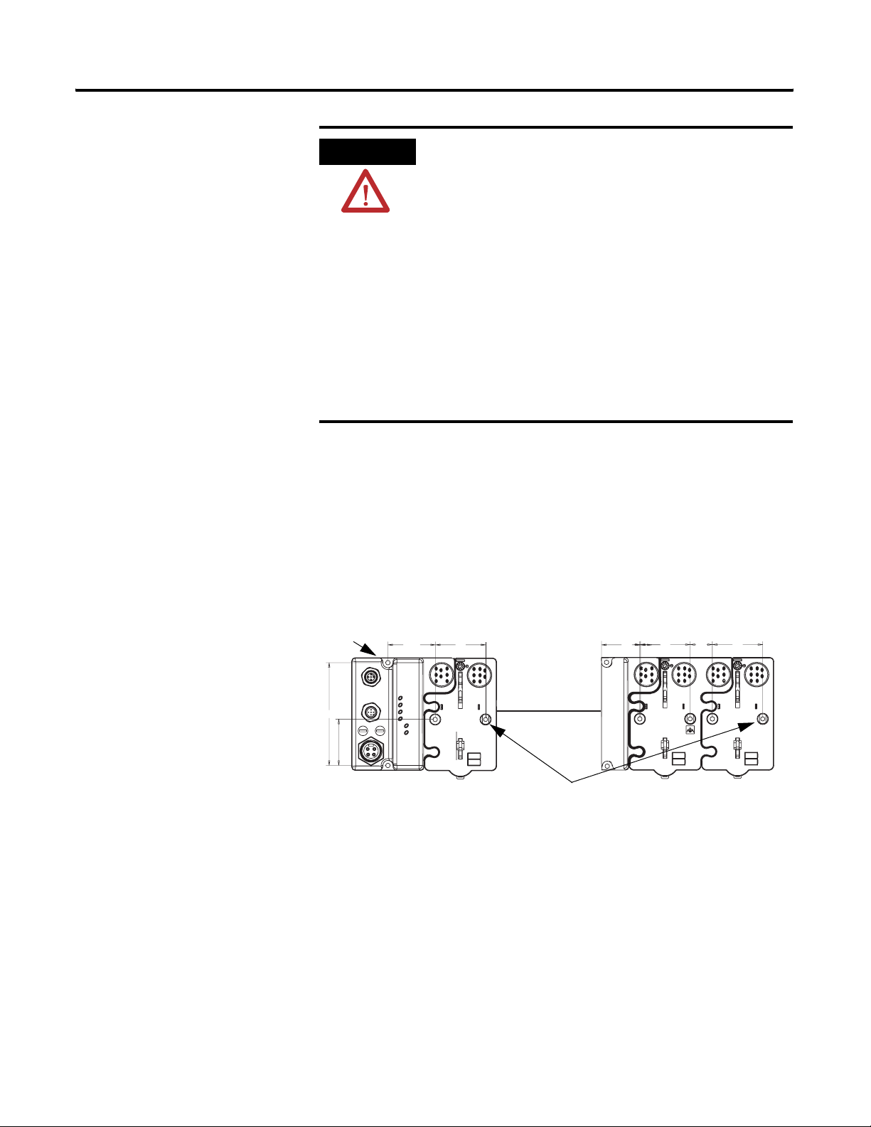
Refer to the drilling dimensions mounting illustration for the extension
unit.
Drilling Dimensions
4.02 in.
102 mm
Adapter
1.81 in.
1.9 in.
47.2 mm
2.0 in.
50 mm
Install the extension unit as follows:
1. Lay out the required points as shown in the drilling dimension
drawing.
2. Drill the necessary holes for #8 (M4) machine or self-tapping
screws.
3. Mount the extension unit using #8 (M4) screws.
Total length of cable
is 1M (EXT1) or
3M (EXT3)
Ground lug connection
0.94 in.
23.9 mm
0.87 in.
22 mm
2.0 in.
50 mm
43839
4. Ground the system using the ground lug connection. (The
ground lug connection is also a mounting hole.)
Publication 1738-IN018A-EN-E - December 2004
Page 4

4 ArmorPoint Extension Units, Series A
Module will bridge the extension unit and the base
Add I/O Modules to the Extension Unit
Add I/O modules to the extension unit
Module will bridge the extension unit and the base
ControlNet A
ControlNet B
X1
X10
P
O
A
W
U
E
X
R
Add I/O modules to the extension unit. Refer to the illustration.
1738-FPD
Power Distribution
1738-OB2EM12/A
24V dc 0.5Amp
1738-ACNR
Adapter
Status
PontBus
Status
ControlNet A
Status
ControlNet B
Status
System
Power
Field
Power
Out
1
0
MOD
NET
0
1
P
O
A
W
U
E
X
R
43840
1. Position the module vertically above the extension unit and
mounting base. The module will bridge the extension unit and
the mounting base.
0
1738-OB2EM12/A
24V dc 0.5Amp
Out
1
MOD
NET
0
1
2. Push the module down until it engages the latching mechanism.
You will hear a clicking sound when the module is properly
engaged.
The locking mechanism will lock the module to the base.
Publication 1738-IN018A-EN-E - December 2004
Page 5

ArmorPoint Extension Units, Series A 5
Extension Unit Application Rules
All the following rules apply for both the 1738-EXT1 and 1738-EXT3
extension unit.
• For all adapters except the 1738-ADNX:
• Up to four extension units can be used per network adapter.
• For the 1738-ADNX adapter:
• Only one extension unit can be used if there are fewer than
32 modules on the backplane.
• The first module after an extension unit must be either a
1738-FPD or a 1738-EP24DC.
– A 1738-EP24DC is needed:
– if additional backplane power is needed because of
module current consumption, or
– after 2 extension units.
– A 1738-FPD is needed in all other configurations. The only
exception to this rule is if the modules in the segment after
the extension unit are only 1738-IT2IM12s, 1738-IR2M12s,
1738-OW4M12s, or 1738-OW4M12ACs. If on ly these modules
are used, no 1738-FPD or 1738-EP24DC is needed.
• The number or mix of modules you use between extension
cables does not matter as long as you do not exceed the rated
adapter or 1738-EP24DC current output.
Publication 1738-IN018A-EN-E - December 2004
Page 6

6 ArmorPoint Extension Units, Series A
Specifications
ArmorPoint Extension Units
Operating Temperature IEC 60068-2-1 (Test Ad, Operating Cold),
Storage Temperature IEC 60068-2-1 (Test Ab, Un-packaged Non-operating Cold),
Relative Humidity IEC 60068-2-30 (Test Db, Un-packaged Non-operating Damp Heat):
Shock IEC60068-2-27 (Test Ea, Unpackaged Shock):
Vibration IEC60068-2-6 (Test Fc, Operating):
ESD Immunity IEC 61000-4-2:
Radiated RF Immunity IEC 61000-4-3:
Emissions CSPR 11:
Enclosure Type Rating Meets IP65/66/67 (when marked)
Mounting Base Screw Torque #8 screw, 7.5 in. lbs. in Aluminum, 16 in. lbs. in Steel
Certifications:
(when product is marked)
1. See the Product Certification link at www.ab.com for Declarations of Conformity, Certificates, and other certification details.
1
Following are specifications for the 1738 ArmorPoint extension units.
IEC 60068-2-2 (Test Bd, Operating Dry Heat),
IEC 60068-2-14 (Test Nb, Operating Thermal Shock):
-20 to 60°C (-4 to 140°F)
IEC 60068-2-2 (Test Bb, Un-packaged Non-operating Dry Heat),
-40 to 85°C (-40 to 185°F)
5-95% non-condensing
Operating 30g
Non-operating 50g
5g @ 10-500Hz
6kV contact discharges
8kV air discharges
10V/m with 1kHz sine-wave 80%AM from 30MHz to 2000MHz
10V/m with 200Hz 50% Pulse 100%AM at 900Mhz
10V/m with 200Hz 50% Pulse 100%AM at 1890Mhz
Group 1, Class A
c-UL-us UL Listed Industrial Control Equipment, certified for US and Canada
CE European Union 89/336/EEC EMC Directive, compliant with:
EN 61000-6-4; Industrial Emissions
EN 50082-2; Industrial Immunity
EN 61326; Meas./Control/Lab., Industrial Requirements
EN 61000-6-2; Industrial Immunity
C-Tick Australian Radiocommunications Act, compliant with:
AS/NZS CISPR 11; Industrial Emissions
Publication 1738-IN018A-EN-E - December 2004
Page 7

Notes:
ArmorPoint Extension Units, Series A 7
Publication 1738-IN018A-EN-E - December 2004
Page 8

Rockwell Automation Support
Rockwell Automation provides technical information on the web to assist you in using its products. At
http://support.rockwellautomation.com, you can find technical manuals, a knowledge base of FAQs, technical and
application notes, sample code and links to software service packs, and a MySupport feature that you can customize
to make the best use of these tools.
For an additional level of technical phone support for installation, configuration and troubleshooting, we offer
TechConnect Support programs. For more information, contact your local distributor or Rockwell Automation
representative, or visit http://support.rockwellautomation.com.
Installation Assistance
If you experience a problem with a hardware module within the first 24 hours of installation, please review the
information that's contained in this manual. You can also contact a special Customer Support number for initial help
in getting your module up and running:
United States 1.440.646.3223
Monday – Friday, 8am – 5pm EST
Outside United States Please contact your local Rockwell Automation representative for any technical support issues.
New Product Satisfaction Return
Rockwell tests all of its products to ensure that they are fully operational when shipped from the manufacturing
facility. However, if your product is not functioning and needs to be returned:
United States Contact your distributor. You must provide a Customer Support case number (see phone number
above to obtain one) to your distributor in order to complete the return process.
Outside United States Please contact your local Rockwell Automation representative for return procedure.
ArmorPoint is a trademark of Rockwell Automation.
Publication 1738-IN018A-EN-E - December 2004 8 PN 957824-44
ö
Copyright © 2004 Rockwell Automation, Inc. All rights reserved. Printed in the U.S.A.
 Loading...