

Page 1
Integration Document
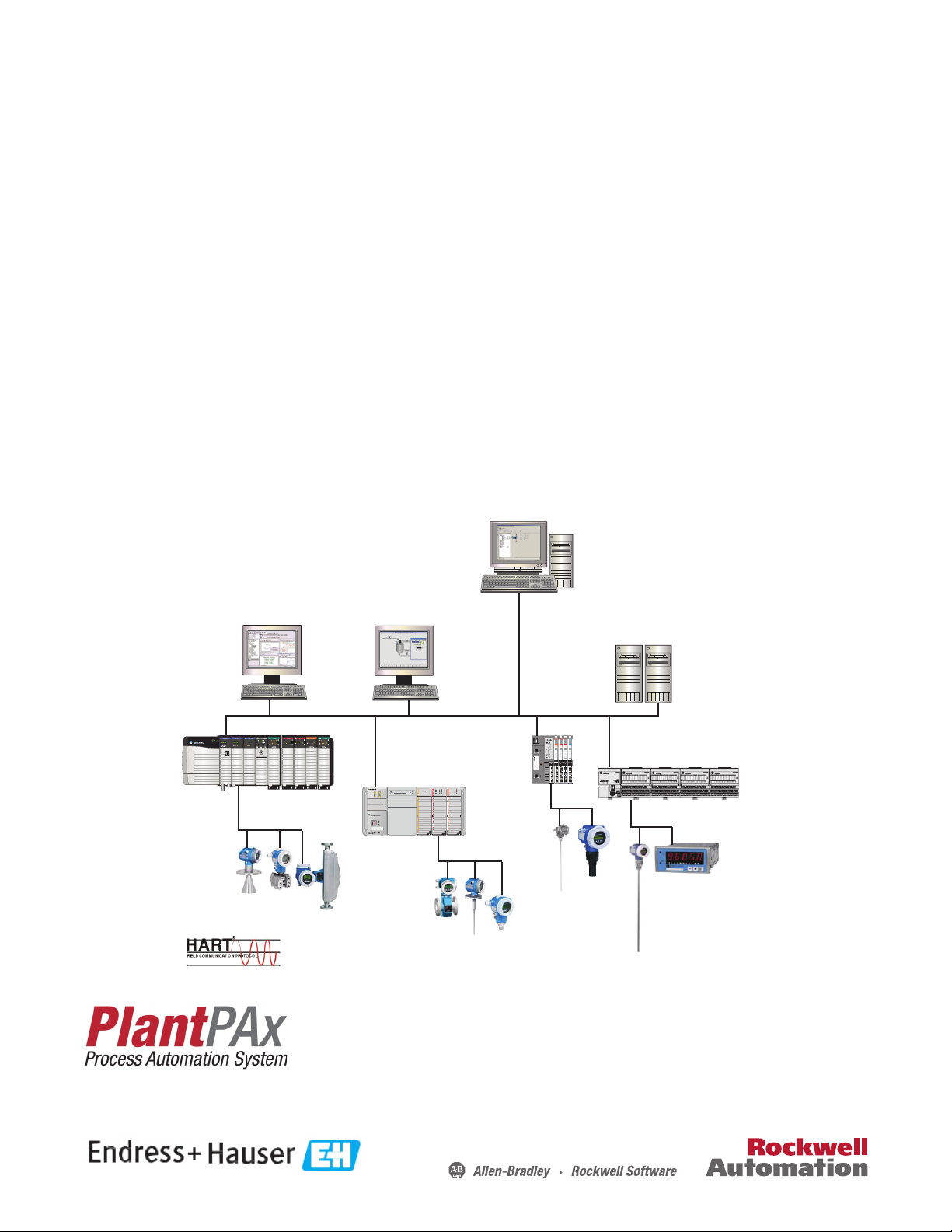
Endress+Hauser Instruments via HART to the PlantPAx
Process Automation System
Systems with Analog I/O Modules: 1756-IF8H, 1756-IF8IH, 1756-IF16H, 1794-IF8IH, 1769sc-IF4IH, 1734sc-IE2CH, 1734sc-IE4CH
Endress+Hauser Devices: Promag 53 Electromagnetic, Flowmeter, Proline T-mass 65 Thermal Flowmeter, Promass 83 Coriolis
Mass Flowmeter, Prowirl 73 Flowmeter, Prosonic M Ultrasonic Level, Levelflex M Guided Radar Level, Micropilot M Radar Level,
Deltabar S Differential Pressure, Prosonic S Transmitter, Cerabar S Pressure Transmitter, iTEMP TMT162 Temperature Transmitter,
iTEMP TMT182 Temperature Transmitter, Liquiline M CM42 Transmitter
Module
Module
Module
Module
Status
Status
Status
Status
Network
Network
Network
Network
Status
Status
Status
Status
NODE:
NODE:
NODE:
NODE:
24VDC
220 VAC
Relay
120 VAC
Sink
Input
Output
Input
Input
0
0
0
0
4
0
0
0
0
4
1
1
1
1
5
1
1
1
1
1
5
2
2
2
2
6
2
2
2
6
3
3
3
3
7
3
3
3
7
1734
1734
1734
1734
OW4
IB8
IA4
IM4
L33ERM
RUN
NS
LINK 1
FORCE
I/O
LINK 2
SD
OK
RUN
REM
PROG
XX:XX:XX:XX:XX:XX
1 (Front)
2 (Rear)
AC/DC OUT
RELAY115 VAC
Page 2
Important User Information
IMPORTANT
Solid-state equipment has operational characteristics differing from those of electromechanical equipment. Safety
Guidelines for the Application, Installation and Maintenance of Solid State Controls (publication SGI-1.1
your local Rockwell Automation® sales office or online at http://www.rockwellautomation.com/literature/
important differences between solid-state equipment and hard-wired electromechanical devices. Because of this difference,
and also because of the wide variety of uses for solid-state equipment, all persons responsible for applying this equipment
must satisfy themselves that each intended application of this equipment is acceptable.
In no event will Rockwell Automation, Inc. be responsible or liable for indirect or consequential damages resulting from the
use or application of this equipment.
The examples and diagrams in this manual are included solely for illustrative purposes. Because of the many variables and
requirements associated with any particular installation, Rockwell Automation, Inc. cannot assume responsibility or
liability for actual use based on the examples and diagrams.
No patent liability is assumed by Rockwell Automation, Inc. with respect to use of information, circuits, equipment, or
software described in this manual.
Reproduction of the contents of this manual, in whole or in part, without written permission of Rockwell Automation,
Inc., is prohibited.
Throughout this manual, when necessary, we use notes to make you aware of safety considerations.
available from
) describes some
WARNING: Identifies information about practices or circumstances that can cause an explosion in a hazardous environment,
which may lead to personal injury or death, property damage, or economic loss.
ATTENTION: Identifies information about practices or circumstances that can lead to personal injury or death, property
damage, or economic loss. Attentions help you identify a hazard, avoid a hazard, and recognize the consequence.
SHOCK HAZARD: Labels may be on or inside the equipment, for example, a drive or motor, to alert people that dangerous
voltage may be present.
BURN HAZARD: Labels may be on or inside the equipment, for example, a drive or motor, to alert people that surfaces may
reach dangerous temperatures.
Identifies information that is critical for successful application and understanding of the product.
Allen-Bradley, Rockwell Software, Rockwell Automation, CompactLogix, ControlLogix, FactoryTalk, RSLogix , and and TechConnect are trademarks of Rockwell Automation, Inc.
Trademarks not belonging to Rockwell Automation are property of their respective companies.
Page 3

Table of Contents
Table of Contents
Important User Information . . . . . . . . . . . . . . . . . . . . . . . . . . . . . . . . . . . . . . . . 2
Preface
Installation
Configure the HART Device in RSLogix
5000 Programming Software
Preferred Integration . . . . . . . . . . . . . . . . . . . . . . . . . . . . . . . . . . . . . . . . . . . . . . . 7
Application Overview . . . . . . . . . . . . . . . . . . . . . . . . . . . . . . . . . . . . . . . . . . . . . . 8
Control System . . . . . . . . . . . . . . . . . . . . . . . . . . . . . . . . . . . . . . . . . . . . . . 10
HART Handheld Device (Optional) . . . . . . . . . . . . . . . . . . . . . . . . . . 10
System Details . . . . . . . . . . . . . . . . . . . . . . . . . . . . . . . . . . . . . . . . . . . . . . . . . . . 11
Hardware Components. . . . . . . . . . . . . . . . . . . . . . . . . . . . . . . . . . . . . . . 11
Software Components . . . . . . . . . . . . . . . . . . . . . . . . . . . . . . . . . . . . . . . . 11
Performance Considerations . . . . . . . . . . . . . . . . . . . . . . . . . . . . . . . . . . . . . . 12
Additional Resources . . . . . . . . . . . . . . . . . . . . . . . . . . . . . . . . . . . . . . . . . . . . . 12
Chapter 1
Connect a 2-Wire Field Instrument . . . . . . . . . . . . . . . . . . . . . . . . . . . . . . . 13
Connect a 4-Wire Field Instrument . . . . . . . . . . . . . . . . . . . . . . . . . . . . . . . 17
Chapter 2
Configure a HART Input Module in a ControlLogix System . . . . . . . . 21
Configure a HART Input Module in a Compact I/O System . . . . . . . . 27
Configure a HART Input Module in a FLEX I/O System . . . . . . . . . . . 29
Configure a HART Input Module in a POINT I/O System . . . . . . . . . 31
Configure A HART Input Module via CIP Messages . . . . . . . . . . . . . . . 34
Configure the HART Device in
FactoryTalk AssetCenter Software
Configure the HART Device in E+H
Fieldcare Software
Chapter 3
Configure a HART Input Module. . . . . . . . . . . . . . . . . . . . . . . . . . . . . . . . . 35
Configure the DTM Network Path. . . . . . . . . . . . . . . . . . . . . . . . . . . . . . . . 36
Configure a HART Device . . . . . . . . . . . . . . . . . . . . . . . . . . . . . . . . . . . . . . . 43
Configure a FLEX I/O Module . . . . . . . . . . . . . . . . . . . . . . . . . . . . . . . . . . . 50
Chapter 4
Configure a HART Input Module and Device. . . . . . . . . . . . . . . . . . . . . . 53
Access Instrument Data . . . . . . . . . . . . . . . . . . . . . . . . . . . . . . . . . . . . . . . . . . 56
Additional Functions. . . . . . . . . . . . . . . . . . . . . . . . . . . . . . . . . . . . . . . . . . . . . 58
Rockwell Automation Publication PROCES-UM002A-EN-P - July 2014 3
Page 4

Table of Contents
Chapter 5
Visualization
Promag 53 Electromagnetic
Flowmeter
Add-On Instructions . . . . . . . . . . . . . . . . . . . . . . . . . . . . . . . . . . . . . . . . . . . . . 59
Download the Add-On Instructions . . . . . . . . . . . . . . . . . . . . . . . . . . . 60
Import Add-On Instructions . . . . . . . . . . . . . . . . . . . . . . . . . . . . . . . . . . 61
Add an Add-On Instruction to a Routine. . . . . . . . . . . . . . . . . . . . . . . 63
Configure I_AB56IF8H . . . . . . . . . . . . . . . . . . . . . . . . . . . . . . . . . . . . . . 65
Configure I_AB56IFxH_Chan . . . . . . . . . . . . . . . . . . . . . . . . . . . . . . . . 67
Configure P_AIn56H. . . . . . . . . . . . . . . . . . . . . . . . . . . . . . . . . . . . . . . . . 68
Link an Add-On Instruction to Graphics in FactoryTalk View SE
Software . . . . . . . . . . . . . . . . . . . . . . . . . . . . . . . . . . . . . . . . . . . . . . . . . . . . . 70
Add Library Components to an HMI Application. . . . . . . . . . . . . . . 71
Global Object . . . . . . . . . . . . . . . . . . . . . . . . . . . . . . . . . . . . . . . . . . . . . . . . . . . . 75
Add Global Objects to a Display . . . . . . . . . . . . . . . . . . . . . . . . . . . . . . . 75
Configure Tags . . . . . . . . . . . . . . . . . . . . . . . . . . . . . . . . . . . . . . . . . . . . . . . 77
Faceplates. . . . . . . . . . . . . . . . . . . . . . . . . . . . . . . . . . . . . . . . . . . . . . . . . . . . . . . . 81
Appendix A
Measured Variable . . . . . . . . . . . . . . . . . . . . . . . . . . . . . . . . . . . . . . . . . . . . 84
Signals from Instrument to Control System . . . . . . . . . . . . . . . . . . . . . 84
Connect a Promag 53 Flowmeter . . . . . . . . . . . . . . . . . . . . . . . . . . . . . . . . . . 85
Configure a Promag 53 Flowmeter. . . . . . . . . . . . . . . . . . . . . . . . . . . . . . . . . 86
Pulsating Flow. . . . . . . . . . . . . . . . . . . . . . . . . . . . . . . . . . . . . . . . . . . . . . . . 87
Batching . . . . . . . . . . . . . . . . . . . . . . . . . . . . . . . . . . . . . . . . . . . . . . . . . . . . . 88
Proline T-mass 65 Thermal
Flowmeter
Promass 83 Coriolis Mass Flowmeter
Prowirl 73 Flowmeter
Appendix B
Measured Variables . . . . . . . . . . . . . . . . . . . . . . . . . . . . . . . . . . . . . . . . . . . 90
Signals from Instrument to Control System . . . . . . . . . . . . . . . . . . . . . 90
Connect a Proline T-mass 65 Flowmeter . . . . . . . . . . . . . . . . . . . . . . . . . . . 91
Configure a Proline T-mass 65 Flowmeter. . . . . . . . . . . . . . . . . . . . . . . . . . 92
Appendix C
Measured Variables . . . . . . . . . . . . . . . . . . . . . . . . . . . . . . . . . . . . . . . . . . . 94
Signals from Instrument to Control System . . . . . . . . . . . . . . . . . . . . . 94
Connect a Promass 83 Flowmeter. . . . . . . . . . . . . . . . . . . . . . . . . . . . . . . . . . 94
Configure a Promass 83 Flowmeter . . . . . . . . . . . . . . . . . . . . . . . . . . . . . . . . 96
Appendix D
Measured Variables . . . . . . . . . . . . . . . . . . . . . . . . . . . . . . . . . . . . . . . . . . . 98
Signals from Instrument to Control System . . . . . . . . . . . . . . . . . . . . . 99
Connect a Prowirl 73 Flowmeter . . . . . . . . . . . . . . . . . . . . . . . . . . . . . . . . . . 99
Wiring Diagram . . . . . . . . . . . . . . . . . . . . . . . . . . . . . . . . . . . . . . . . . . . . . 101
Configure a Prowirl 73 Flowmeter . . . . . . . . . . . . . . . . . . . . . . . . . . . . . . . . 102
4 Rockwell Automation Publication PROCES-UM002A-EN-P - July 2014
Page 5

Appendix E
Table of Contents
Prosonic M Ultrasonic Level
Levelflex M Guided Radar Level
Micropilot M Radar Level
Cerabar S Pressure Transmitter
Measured Variables . . . . . . . . . . . . . . . . . . . . . . . . . . . . . . . . . . . . . . . . . . 104
Signals from Instrument to Control System. . . . . . . . . . . . . . . . . . . . 104
Connect a Prosonic M Ultrasonic Level. . . . . . . . . . . . . . . . . . . . . . . . . . . 105
Configure a Prosonic M Ultrasonic Level . . . . . . . . . . . . . . . . . . . . . . . . . 107
Appendix F
Measured Variables . . . . . . . . . . . . . . . . . . . . . . . . . . . . . . . . . . . . . . . . . . 110
Signals from Instrument to Control System. . . . . . . . . . . . . . . . . . . . 111
Connect a Levelflex M Guided Level-Radar . . . . . . . . . . . . . . . . . . . . . . . 111
Configure a Levelflex M Guided Level-Radar . . . . . . . . . . . . . . . . . . . . . . 113
Appendix G
Measured Variables . . . . . . . . . . . . . . . . . . . . . . . . . . . . . . . . . . . . . . . . . . 116
Signals from Instrument to Control System. . . . . . . . . . . . . . . . . . . . 116
Connect a Micropilot M Level-Radar. . . . . . . . . . . . . . . . . . . . . . . . . . . . . 117
Configure a Micropilot M Level-Radar . . . . . . . . . . . . . . . . . . . . . . . . . . . 118
Appendix H
Measured Variables . . . . . . . . . . . . . . . . . . . . . . . . . . . . . . . . . . . . . . . . . . 121
Signals from Instrument to Control System. . . . . . . . . . . . . . . . . . . . 121
Connect a Cerabar S Pressure Transmitter . . . . . . . . . . . . . . . . . . . . . . . . 122
Configure a Cerabar S Pressure Transmitter. . . . . . . . . . . . . . . . . . . . . . . 123
Pressure Measuring Mode . . . . . . . . . . . . . . . . . . . . . . . . . . . . . . . . . . . 123
Level Measuring Mode . . . . . . . . . . . . . . . . . . . . . . . . . . . . . . . . . . . . . . 123
Deltabar S Differential Pressure
Prosonic S Transmitter
Appendix I
Metal Measuring Cell. . . . . . . . . . . . . . . . . . . . . . . . . . . . . . . . . . . . . . . . 126
Measured Variable. . . . . . . . . . . . . . . . . . . . . . . . . . . . . . . . . . . . . . . . . . . 128
Signals from Instrument to Control System. . . . . . . . . . . . . . . . . . . . 128
Connect a Deltabar S Differential Pressure . . . . . . . . . . . . . . . . . . . . . . . . 129
Configure a Deltabar S Differential Pressure. . . . . . . . . . . . . . . . . . . . . . . 130
Flow Measuring Mode . . . . . . . . . . . . . . . . . . . . . . . . . . . . . . . . . . . . . . . 130
Level Measuring Mode. . . . . . . . . . . . . . . . . . . . . . . . . . . . . . . . . . . . . . . 130
Pressure Measuring Mode . . . . . . . . . . . . . . . . . . . . . . . . . . . . . . . . . . . . 131
Appendix J
Measured Variables . . . . . . . . . . . . . . . . . . . . . . . . . . . . . . . . . . . . . . . . . . 134
Signals from Instrument to Control System. . . . . . . . . . . . . . . . . . . . 135
Connect a Prosonic S Transmitter. . . . . . . . . . . . . . . . . . . . . . . . . . . . . . . . 135
Sensor Connection . . . . . . . . . . . . . . . . . . . . . . . . . . . . . . . . . . . . . . . . . . 137
Configure a Prosonic S Transmitter . . . . . . . . . . . . . . . . . . . . . . . . . . . . . . 138
Rockwell Automation Publication PROCES-UM002A-EN-P - July 2014 5
Page 6

Table of Contents
Appendix K
iTEMP TMT162 Temperature
Transmitter
iTEMP TMT182 Temperature
Transmitter
Liquiline M CM42 Transmitter
Index
Measured Variables . . . . . . . . . . . . . . . . . . . . . . . . . . . . . . . . . . . . . . . . . . 140
Signals from Instrument to Control System . . . . . . . . . . . . . . . . . . . . 140
Connect an iTEMP TMT162 Temperature Transmitter . . . . . . . . . . . 141
Configure an iTEMP TMT162 Temperature Transmitter. . . . . . . . . . 142
Appendix L
Measured Variables . . . . . . . . . . . . . . . . . . . . . . . . . . . . . . . . . . . . . . . . . . 143
Signals from Instrument to Control System . . . . . . . . . . . . . . . . . . . . 144
Connect an iTEMP TMT182 Temperature Transmitter . . . . . . . . . . . 144
Configure an iTEMP TMT182 Temperature Transmitter. . . . . . . . . . 145
Appendix M
Measuring System Examples . . . . . . . . . . . . . . . . . . . . . . . . . . . . . . . . . . 148
Measured Variables . . . . . . . . . . . . . . . . . . . . . . . . . . . . . . . . . . . . . . . . . . 149
Signals from Instrument to Control System . . . . . . . . . . . . . . . . . . . . 149
Connect a Liquiline M CM42 Transmitter . . . . . . . . . . . . . . . . . . . . . . . . 150
Housing Grounding . . . . . . . . . . . . . . . . . . . . . . . . . . . . . . . . . . . . . . . . . 150
Stainless Steel Housing. . . . . . . . . . . . . . . . . . . . . . . . . . . . . . . . . . . . . . . 150
Supply and Signal Circuit . . . . . . . . . . . . . . . . . . . . . . . . . . . . . . . . . . . . 151
Sensor Connection: pH / ORP . . . . . . . . . . . . . . . . . . . . . . . . . . . . . . . 151
Sensor Connection: Conductivity. . . . . . . . . . . . . . . . . . . . . . . . . . . . . 154
Sensor Connection: pH / ORP / ISFET / Oxygen (digital sensors) . .
155
Configure a Liquiline M CM42 Transmitter . . . . . . . . . . . . . . . . . . . . . . 156
Menu Structure, Top Hierarchy Level . . . . . . . . . . . . . . . . . . . . . . . . . 156
Quick Setup. . . . . . . . . . . . . . . . . . . . . . . . . . . . . . . . . . . . . . . . . . . . . . . . . 156
6 Rockwell Automation Publication PROCES-UM002A-EN-P - July 2014
Page 7
Preface
Preferred Integration
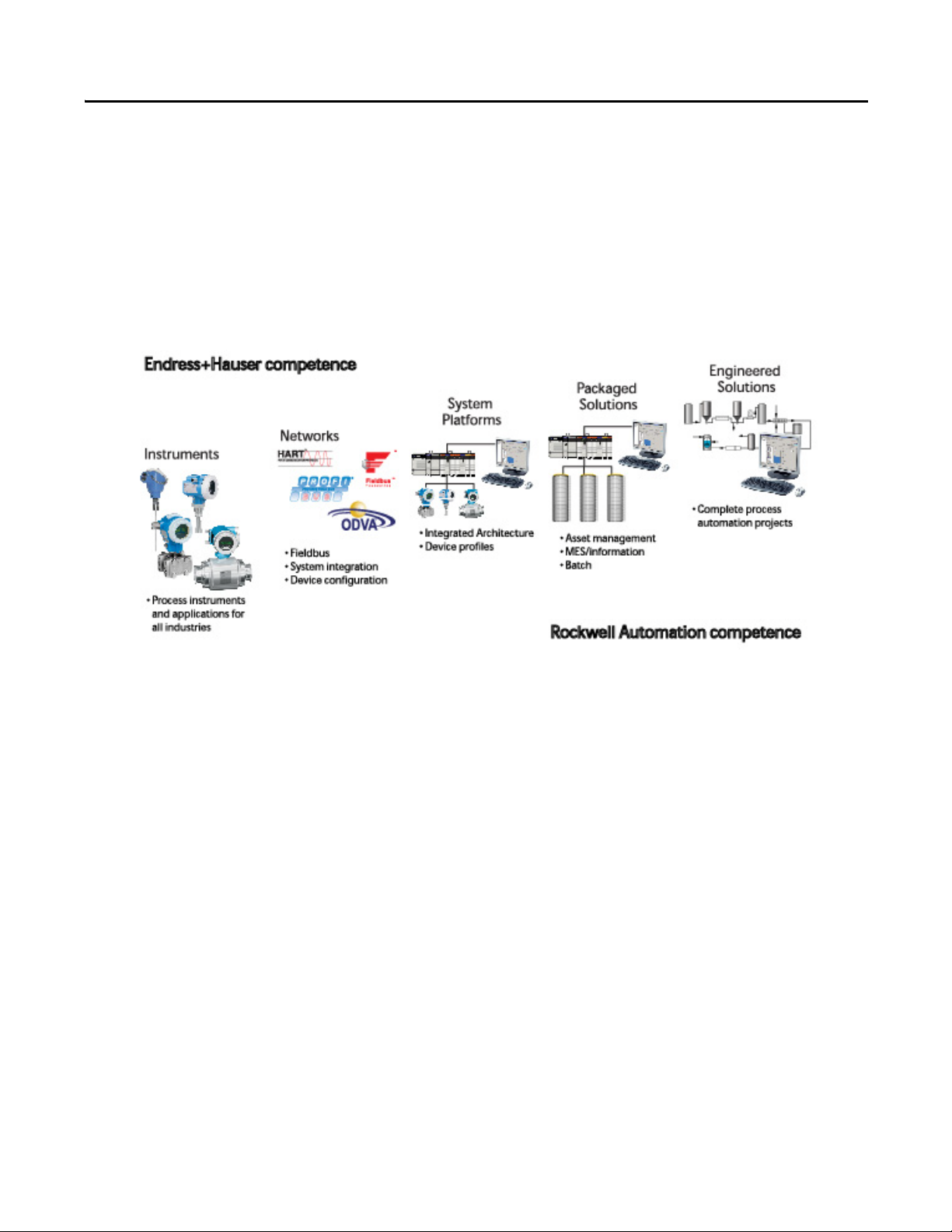
Rockwell Automation and Endress+Hauser have strengthened their strategic
alliance to provide complete process automation solutions that use best-in-class
instrumentation, software, and control systems.
There are hundreds of different components in a typical plant: controllers,
remote I/O, electrical drives, safety equipment, and sensors. Each must be
integrated, configured and optimized during start-up and operation. Recognizing
the challenges this creates, Rockwell Automation and Endress+Hauser are
focused on providing you with scalable, off-the-shelf solutions.
To supply robust system solutions, Rockwell Automation pre-tests many thirdparty manufactured HART, FOUNDATION Fieldbus, and Profibus field
devices in the system test laboratory for compatibility with the Integrated
Architecture based plant automation system. Each field device is connected to
the Rockwell Automation Integrated Architecture based system and is subjected
to interoperability testing procedures similar to operating procedures in your
plant. The results of each field test are recorded in a test report for integration
planning purposes.
For Endress+Hauser field devices, an additional step provides an “Integration
Document” and “Interoperability Statement” for each tested instrument. The
Integration Document provides information on installation, configuration,
startup, and operation of the integrated system. The Interoperability Statement is
assurance that the Endress+Hauser field device meets Integrated Architecture
system interoperability performance measures, as jointly established by Rockwell
Automation and Endress+Hauser and verified through completion of common
test procedures performed by either company. Both the Integration Document
and Interoperability Statement ensure a no risk solution highlighted by ease of
integration and optimum performance.
Rockwell Automation Publication PROCES-UM002A-EN-P - July 2014 7
Page 8

Preface
The overall mission of the alliance is to provide you with proven solutions that
combine field instrumentation with fieldbus networks, such as HART,
FOUNDATION Fieldbus, and Profibus networks, with asset management
capabilities and Rockwell Automation’s system capabilities to provide a total
engineered solution.
Through preferred integration and support of increasing requirements for plantwide control, the alliance offers the following benefits:
• Reduced integration costs throughout engineering, commissioning, and
start-up
• Optimized plant availability and output
• Ensured product quality and consistency
• Optimized traceability to meet regulatory demands
• Predictive maintenance through intelligent instruments
For new construction, process improvements at an existing plant, or operating
cost reductions, the alliance delivers the following:
• Integration reduces risk, reduces integration costs, and protects investment
with assured interoperability. Both companies believe open systems and
standardized interfaces bring maximum benefits.
• Advanced diagnostics with plant-wide support offers better visibility of
plant health and easier access to instrument diagnostics, which leads to
faster troubleshooting and improves decision-making.
• Collaborative lifecycle management to design, engineer, and startup
systems faster. This collaboration increases productivity, manages
information about instrumentation assets, optimizes plant assets, and
results in a complete lifecycle management solution.
Application Overview
This document provides a step-by-step approach to integrating Endress+Hauser
devices into a Rockwell Automation Integrated Architecture for Process Control
system.
This Section Describes
Application overview Details about the field instrument and control system.
System details Specifications on the required hardware and software components.
Installation How to:
Configuration How to:
Visualization How to implement and configure a graphical display of device information.
8 Rockwell Automation Publication PROCES-UM002A-EN-P - July 2014
• Connect the measurement instrument to the HART I/O module.
• Connect a HART handheld device.
• Configure the HART I/O module.
• Configure the measurement instrument and manage parameters.
Page 9
Preface
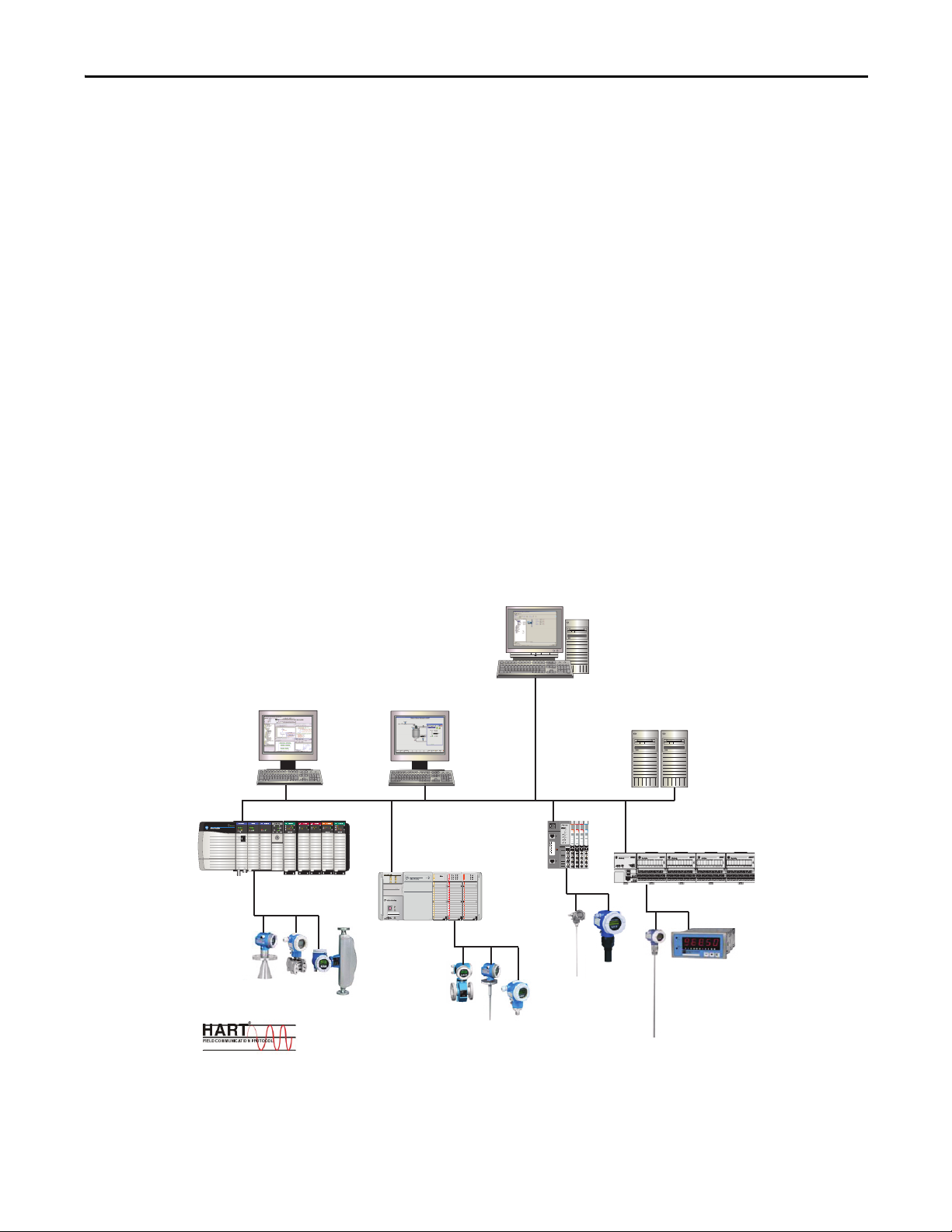
Integrated Asset Management
Process Automation
System Server (PASS)
Operator
Work stati on (OW S)
Engineering
Work stati on (E WS)
POINT I/O
System
CompactLogix
System
ControlLog ix
System
FLEX I/O System
The tested HART devices are the following:
• Promass 83 flowmeter
• Promag 53 flowmeter
• Proline t-mass 65 flowmeter
• Prosonic S transmitter
• Prowirl 73 flowmeter
• Levelflex M guided level-radar
• Micropilot M level-radar
• Prosonic M ultrasonic level
• Liquiline M CM42 transmitter
• Cerabar S pressure transmitter
• Deltabar S differential pressure
• iTEMP TMT162 temperature transmitter
• iTEMP TMT182 temperature transmitter
The ControlLogix platform provides a full range of input and output modules to
span a wide variety of applications. The ControlLogix architecture uses
producer/consumer technology, allowing input information and output status to
be shared by all ControlLogix controllers in the system.
L33ERM
RUN
NS
LINK 1
FORCE
I/O
LINK 2
SD
OK
RUN
REM
PROG
XX:XX:XX:XX:XX:XX
1 (Front)
2 (Rear)
AC/DC OUT
RELAY115 VAC
Module
Module
Module
Module
Status
Status
Status
Status
Network
Network
Network
Network
Status
Status
Status
Status
NODE:
NODE:
NODE:
NODE:
24VDC
220 VAC
Relay
120 VAC
Sink
Input
Output
Input
Input
0
0
0
0
4
0
0
0
0
4
1
1
1
1
5
1
1
1
1
1
5
2
2
2
2
6
2
2
2
6
3
3
3
3
7
3
3
3
7
1734
1734
1734
1734
OW4
IB8
IA4
IM4
Rockwell Automation Publication PROCES-UM002A-EN-P - July 2014 9
Page 10

Preface
Control System
The control system includes these components:
Component Description
Controller The ControlLogix controller is a modular, high performance controller, that uses RSLogix 5000 programming software
to configure, program, and monitor a system. The ControlLogix controller is certified by TUV for SIL 1 and SIL 2
applications.
HART I/O module The HART analog I/O module converts to or from 4...20 mA analog signals and the digital values used in the controller.
The I/O module automatically collects dynamic process data from the HART field instrument. The I/O module also
bridges HART messages from CIP clients to HART field instruments.
Programming software RSLogix 5000 programming software is the design and configuration tool for HART I/O that includes status and
diagnostic information. The software has predefined data struc tures for status and configuration. A common tag
database in the controller allows HMI development to directly reference I/O and controller tags without the need to
manage another database in your HMI software.
Operating software FactoryTalk View Site Edition software is an HMI software program for monitoring, controlling, and acquiring data from
manufacturing operations throughout an enterprise. A generic display provides a graphical representation via
faceplates of the field instrument connected to the HART input module.
Asset management software FactoryTalk AssetCentre software and FieldCare software are options asset management options for configuring and
managing the intelligent field devices in your plant.
• Support Ethernet, HART, and Profibus networks.
• Support Endress+Hauser field instruments.
• Integrate third-party devices, such as actuators, I/O systems, and sensors that support the FDT standard.
• Ensure full functionality for all devices with DTMs.
• Offer generic profile operation for any third-party fieldbus device that does not have a vendor DTM.
HART Handheld Device (Optional)
The Field Xpert handheld device is an industrial PDA with integrated 3.5" touch
screen based on Windows Mobile. The PDA meets the needs and requirements
of the process industry with protection from static electricity, water and dust with
shockproof housing. It is available in different versions for operation both inside
and outside of explosion hazardous areas.
10 Rockwell Automation Publication PROCES-UM002A-EN-P - July 2014
Page 11

Preface
System Details
These components and specifications are recommended for preferred
integration.
Hardware Components
Component Catalog Number
HART device See appropriate appendix
ControlLogix controller 1756-L7 controllers
HART input module (select any one) 1756-IF8H
1756-IF8IH
1756-IF16H
1794-IF8H
1769sc-IF4IH
1734sc-IE2CH
1734sc-IE4CH
Software Components
Component Catalog Number
RSLogix 5000 Enterprise Series programming software,
Professional edition
Includes:
• RSLinx Classic software
• RSLinx Enterprise software
FactoryTalk View Site Edition (SE) software 9701-VWSXXXXXENE
FactoryTalk AssetCentre softare 9515-ASTCAPXXXXX
FieldCare Standard Asset Management software (optional)
9324-RLD700NXENE
SFE551
Includes:
• DTM library
RSLinx Communication DTM software (optional) 1756-Backplane
For specifications of the engineering workstation (EWS) and operator
workstation (OWS), see the Integrated Architecture for Process Control System
Recommendations Manual, publication PROCES-RM001
.
Rockwell Automation Publication PROCES-UM002A-EN-P - July 2014 11
Page 12

Preface
Performance Considerations
Keep in mind these considerations when integrating HART instruments:
• The HART communication protocol has a relatively slow baud rate at
1200/2400 bits per second.
• The 1756-IF8H HART module executes one HART command per
instrument at a time. Analog (4-20ma) data are delivered from all channels
simultaneously.
• The time of execution for Universal Command 3 is estimated from
200...600 ms, but varies based on the complexity and response time of the
instrument.
• Upload and download time of instrument parameters to and from
FieldCare software can take several minutes depending on the instrument.
Additional Resources
These documents contain additional information concerning related products
from Rockwell Automation.
Resource Description
Control System Components
ControlLogix Controllers User Manual, publication 1756-UM001
ControlLogix Analog HART I/O Modules User Manual, publication 1756-UM533 How to install, configure, operate, and maintain a 1756-IF8H input module.
Accessing HART Device Parameters using CIP Messages, Knowledgebase document
required. Please contact your sales representative.)
Operator Components
Add-On Instructions and Faceplates for Visualizing HART Instrument Data in FactoryTalk
View SE, Knowledgebase document (Login required. Please contact your sales
representative.)
FactoryTalk View Site Edition User's Guide Volume 1, publication VIEWSE-UM004
FactoryTalk View Site Edition User's Guide Volume 2, publication VIEWSE-UM005
Faceplates, Add-On Instructions, project files, etc. (Login required. Please contact your
sales representative.)
www.products.endress.com/fieldcare
www.products.endress.com/dtm-download Information about field instrument DTMs.
Process Control Information
Integrated Architecture for Process Control System Recommendations Manual,
publication PROCES-RM001
http://www.rockwellautomation.com/process
http://literature.rockwellautomation.com
http://www.endress.com
How to install, configure, operate, and maintain a ControlLogix controller.
(Login
How to use MSG instructions in controller logic to access instrument parameters.
How to implement the HART Add-On-Instruction in controller logic to work with the
FactoryTalk View faceplates for HART instruments.
How to design, develop, and deploy FactoryTalk View SE applications.
Download AOIs, Faceplates and Global Object graphics, and project files.
Information about FieldCare Asset Management software.
Process system recommendations that organize Rockwell Automation products
functionally as system elements, which can then be applied in proven, scalable
configurations for continuous and batch control.
Information about Rockwell Automation process control and Integration Documents.
Available Rockwell Automation publications, including Integration Documents.
Information about Endress+Hauser field instruments.
You can view or download publications at
http:/www.rockwellautomation.com/literature/
technical documentation, contact your local Allen-Bradley distributor or
Rockwell Automation sales representative.
12 Rockwell Automation Publication PROCES-UM002A-EN-P - July 2014
. To order paper copies of
Page 13
Installation
Top ic Pag e
Connect a 2-Wire Field Instrument 13
Connect a 4-Wire Field Instrument 17
Chapter 1
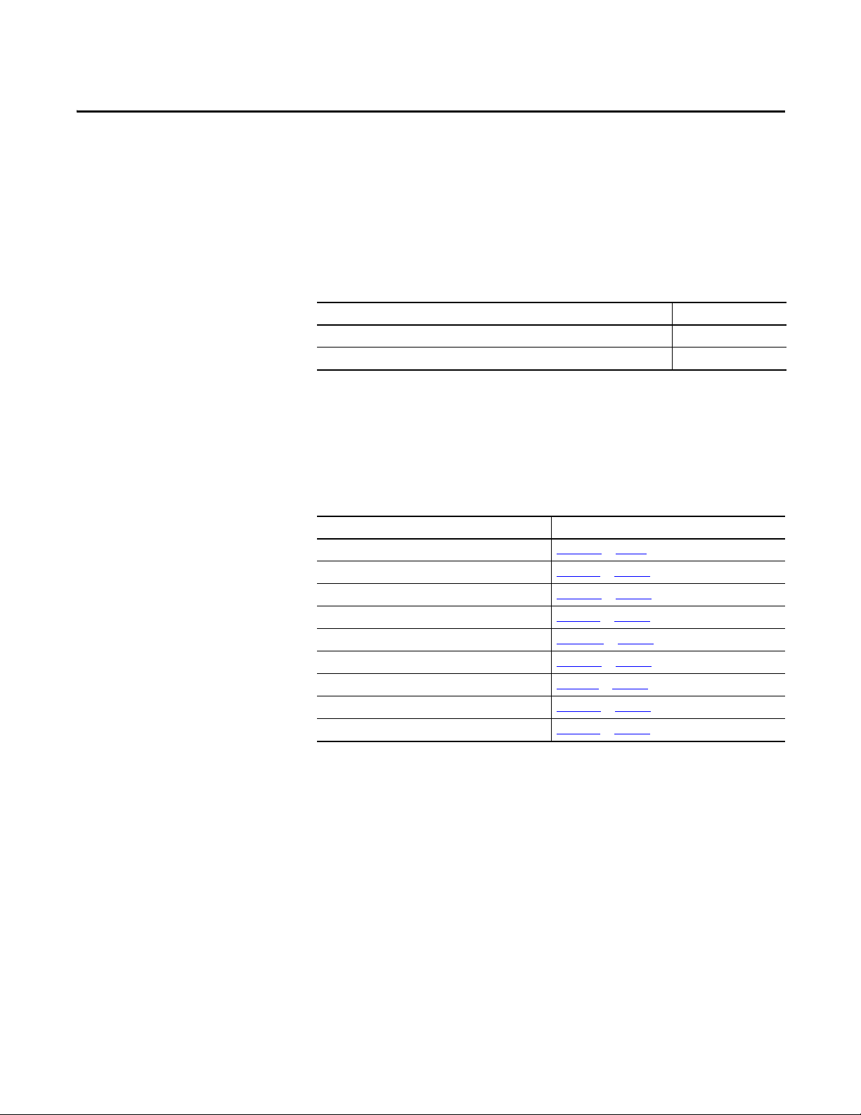
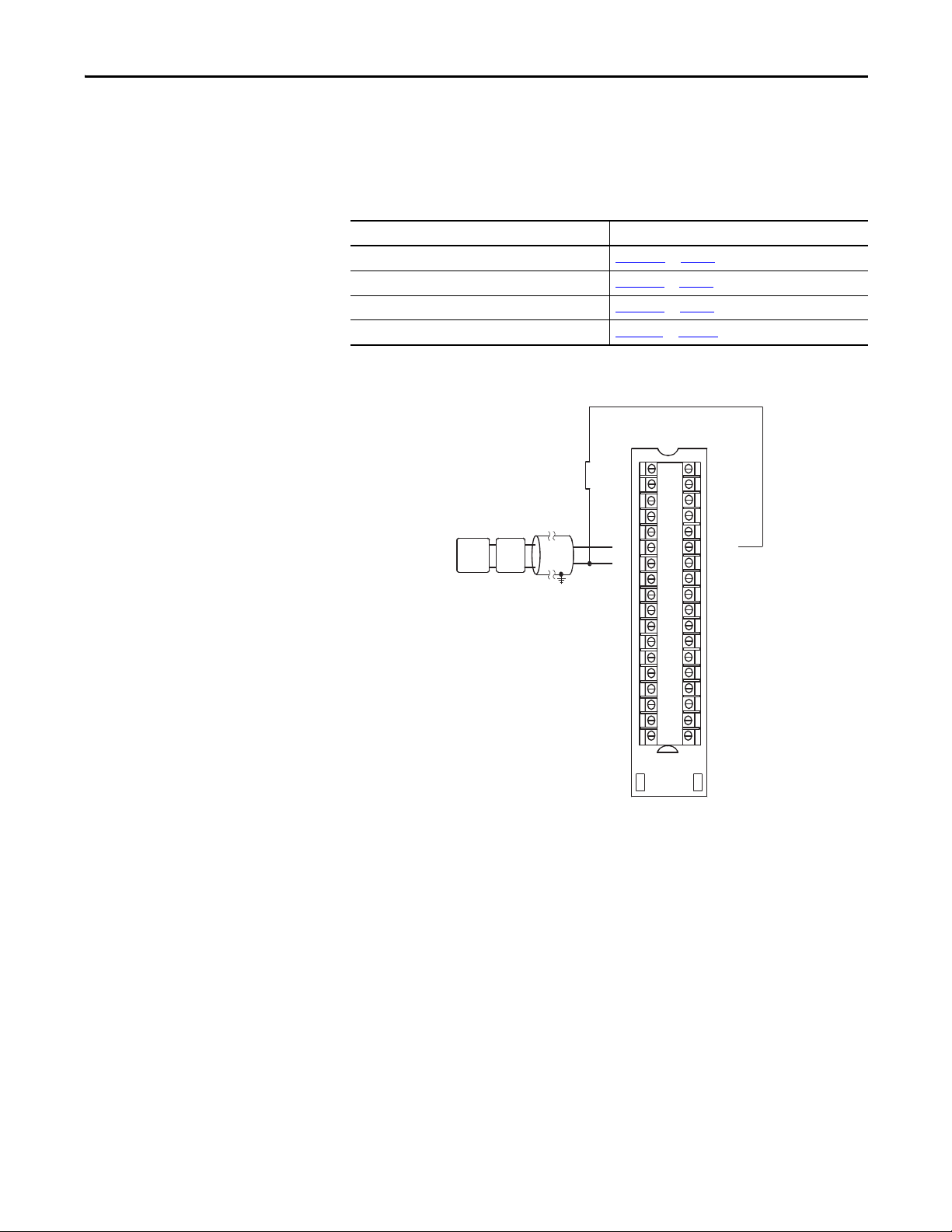
Connect a 2-Wire Field Instrument
HART communication is active only with current inputs. Connect a 2-wire field
instrument to any channel of the HART input module in a 2-wire configuration
for current input.
HART devices that support 2-wire connections include the following.
Device See appendix
Prowirl 73 flowmeter Appendix D on page 97
Levelflex M guided level-radar Appendix F on page 10 9
Micropilot M level-radar Appendix G on page 115
Prosonic M ultrasonic level Appendix E on page 103
Liquiline M CM42 transmitter Appendix M on page 147
Cerabar S pressure transmitter App endix H on page 119
Deltabar S differential pressure Appendix I on page 125
iTEMP TMT162 temperature transmitter Appendix K on page 139
iTEMP TMT182 temperature transmitter Appendix L on page 143
Rockwell Automation Publication PROCES-UM002A-EN-P - July 2014 13
Page 14
Chapter 1 Installation
+
-
+ -
2 Wire HART Device
IN0+
IN1+
IN2+
IN3+
RTN
IN4+
IN5+
IN6+
IN7+
IN8+
IN9+
IN10+
IN11+
RTN
IN12+
IN13+
IN14+
IN15+
IN0IN1IN2IN3RTN
IN4IN5IN6IN7IN8IN9IN10IN11RTN
IN12IN13IN14IN15-
2
4
6
8
10
12
14
16
18
20
22
24
26
28
30
32
34
36
1
3
5
7
9
11
13
15
17
19
21
23
25
27
29
31
33
35
24V DC
Power
Supply
2 Wire
XMTR
Figure 1 - 2-Wire Connection to 1756-IF8H Input Module
2 Wire Current I nput
IN0+
IN0-
IN1+
IN1-
RTN
IN2+
IN2-
IN3+
IN3-
IN4+
IN4-
IN5+
IN5-
RTN
IN6+
IN6-
IN7+
IN7-
24 VDC
Power
Supply
2 Wire
HART
Device
+ -
+
-
1
2
4
6
8
10
12
14
16
18
20
22
24
26
28
30
32
34
36
I RTN-0
3
NC
5
I RTN-1
7
NC
9
RTN
11
I RTN-2
13
NC
15
I RTN-3
17
NC
19
I RTN-4
21
NC
23
I RTN-5
25
NC
27
RTN
29
I RTN-6
31
NC
33
I RTN-7
35
NC
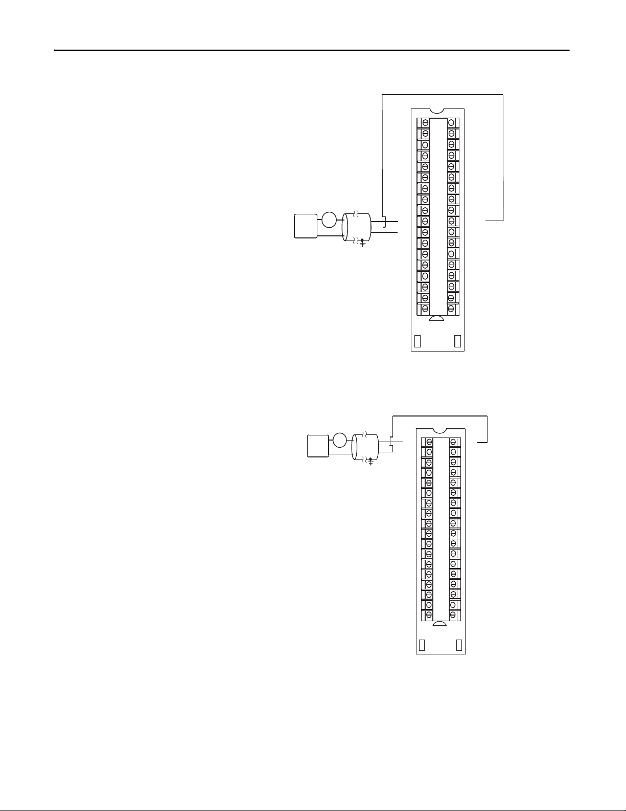
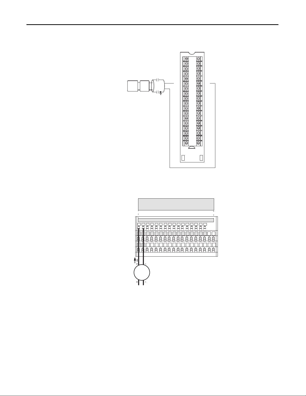
Figure 2 - 2-Wire Connection to 1756-IF16H Input Module
14 Rockwell Automation Publication PROCES-UM002A-EN-P - July 2014
Page 15
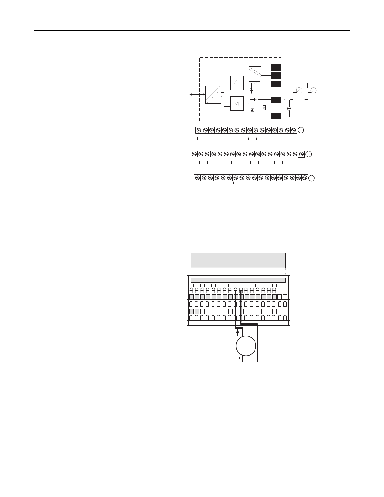
Figure 3 - 2-Wire Connection to 1794-IE8H Input Module
0 1 2 3 4 5 6 7 8 9 10 11 12 13 14 15
33322212029181 24 2526 2728 2930 313217
059484748373635334
51
16
39 40 41 42 43 44 45 46
Row A
Row B
Row C
Row B
Row C
Row A
1794-TB3S shown
Label placed at top of wiring area
Current
input
Flexbus
Bus
uC
0 1 2 3 4 5 6 7 8 9 10 11 12 13 14 15
_
+
17 18 19 20 21 22 23 24 25 26 27 28 29 30 31 32 33
16
_
Chassis
+
Ground
35 36 37 38 39 40 41 42 43 44 45 46 47 48 49 50 51
34
+V -V (COM)
24C dc
Supply In
+V = +24V dc = Terminals C-34 and C-50
-V = COM = C-35 and C-51
Chassis Ground = Terminals B-16, B-33, C-38, C-40…45, and C-47
NC = No connection
For daisy-chaining: Supply in - C-34 (+) and C-35 (-)
_
+
_
+
Ch5
Supply out - C-50 (+) and C-51 (-)
_
+
Ch2
+
Chassis Grounds for Shields
Installation Chapter 1
+V
-V
22 Ω
+
Sig
-
_
+
3hC1hC0hC
_
+
7hC6hC4hC
(1794-TB3G shown)
91 Ω
17V
_
4 to 20mA
Xmit
I
P
Chassis
Ground
+V -V (COM)
CNCN
24C dc
Supply Out
4 to 20mA
Xmit
I
P
40072
A
B
C
Figure 4 - 2-Wire Connection to 1794-IF8IH Input Module
Rockwell Automation Publication PROCES-UM002A-EN-P - July 2014 15
Page 16
Chapter 1 Installation
Figure 5 - 2-Wire Connection to 1769sc-IF4IH Input Module
Ch0+
2 Wire Current Input
24V DC
Power
Supply
2 Wire
XMTR
+ -
+
-
N/C
N/C
Ch1+
Ch1-iRtn
Ch1-
N/C
Ch3+
Ch3-iRtn
Ch3-
Ch0-iRtn
Ch0-
N/C
Ch2+
Ch2-iRtn
Ch2-
N/C
N/C
Figure 6 - 2-Wire Connection to 1734sc-IE2CH Input Module
0
IN 0
2
+ 24
4
COM
6
FGN
1
IN 1
3
+ 24
5
COM
7
FGN
Figure 7 - 2-Wire Connection to 1734sc-IE4CH Input Module
0
IN 0
2
IN 2
4
COM
6
FGN
IN 1
IN 3
+ 24
FGN
1
2 Wire
Device
3
5
7
2 Wire
Device
16 Rockwell Automation Publication PROCES-UM002A-EN-P - July 2014
Page 17
Installation Chapter 1
RTN
IN4+
IN4IN5+
IN5RTN
IN6+
IN6IN7+
IN7-
IN0+
IN0IN1+
IN1-
IN2+
IN2IN3+
IN3-
I RTN- 0
NC
I RTN- 1
NC
I RTN- 2
NC
I RTN- 3
NC
RTN
I RTN- 4
NC
I RTN- 5
NC
RTN
I RTN- 6
NC
I RTN- 7
NC
2
4
6
8
10
12
14
16
18
20
22
24
26
28
30
32
34
36
1
3
5
7
9
11
13
15
17
19
21
23
25
27
29
31
33
35
+
-
+
+
--
4-wire Current Input
4-wire
MTR
24V DC
Power
Supply
Connect a 4-Wire Field Instrument
HART communication is active only with current inputs. Connect a 4-wire field
instrument to any channel of the HART input module in a 4-wire configuration
for current input.
HART devices that support 4-wire connections include the following.
Device See appendix
Promass 83 flowmeter Appendix A on page 83
Promag 53 flowmeter Appendix C on page 93
Proline t-mass 65 flowmeter Appendix B on page 89
Prosonic S transmitter Appendix J on page 133
Figure 8 - 4-Wire Connection to 1756-IF8H Input Module
Rockwell Automation Publication PROCES-UM002A-EN-P - July 2014 17
Page 18
Chapter 1 Installation
+
-
+
--
4 Wire HART Device
IN0+
IN1+
IN2+
IN3+
RTN
IN4+
IN5+
IN6+
IN7+
IN8+
IN9+
IN10+
IN11+
RTN
IN12+
IN13+
IN14+
IN15+
IN0IN1IN2IN3RTN
IN4IN5IN6IN7IN8IN9IN10IN11RTN
IN12IN13IN14IN15-
2
4
6
8
10
12
14
16
18
20
22
24
26
28
30
32
34
36
1
3
5
7
9
11
13
15
17
19
21
23
25
27
29
31
33
35
24V DC
Power
Supply
4 Wire
XMTR
+
Figure 9 - 4-Wire Connection to 1756-IF16H Input Module
Figure 10 - 4-Wire Connection to 1794-IF8IH Input Module
0 1 2 3 4 5 6 7 8 9 10 11 12 13 14 15
16
39 40 41 42 43 44 45 46
Label placed at top of wiring area
Current
input
Row A
33322212029181 24 2526 2728 2930 313217
Row B
51
059484748373635334
Row C
Row A
Row B
Row C
1794-TB3S shown
18 Rockwell Automation Publication PROCES-UM002A-EN-P - July 2014
Page 19
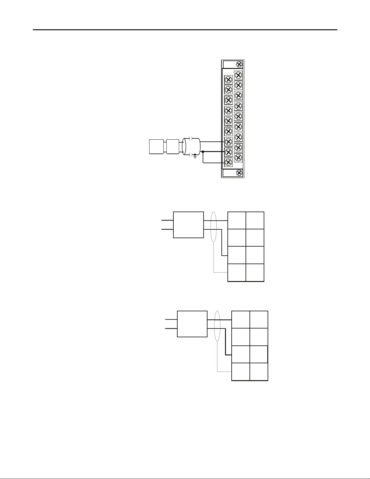
Figure 11 - 4-Wire Connection to 1769sc-IF4IH Input Module
0
IN 0
2
+ 24
4
COM
6
FGN
1
IN 1
3
+ 24
5
COM
7
FGN
4 Wire
Device
AC/DC Pwr
A
Ch0+
+
24V DC
+
-
4 Wire
XMTR
--
Power
Supply
4 Wire Current Input
N/C
N/C
Ch1+
Ch1-iRtn
Ch1-
N/C
+
Ch3+
Ch3-iRtn
Ch3-
Ch0-iRtn
Ch0-
N/C
Ch2+
Ch2-iRtn
Ch2-
N/C
N/C
Installation Chapter 1
Figure 12 - 4-Wire Connection to 1734sc-IE2CH Input Module
Figure 13 - 4-Wire Connection to 1734sc-IE4CH Input Module
0
IN 0
2
IN 2
4
COM
6
FGN
FGN
C/DC Pwr
4 Wire
Device
1
IN 1
3
IN 3
5
+ 24
7
Rockwell Automation Publication PROCES-UM002A-EN-P - July 2014 19
Page 20

Chapter 1 Installation
Notes:
20 Rockwell Automation Publication PROCES-UM002A-EN-P - July 2014
Page 21
Chapter 2
Configure the HART Device in RSLogix 5000 Programming Software
Top ic Pag e
Configure a HART Input Module in a ControlLogix System 21
Configure a HART Input Module in a Compact I/O System 27
Configure a HART Input Module in a FLEX I/O System 29
Configure a HART Input Module in a POINT I/O System 31
The examples in this chapter use RSLogix 5000 programming software,
version 20.
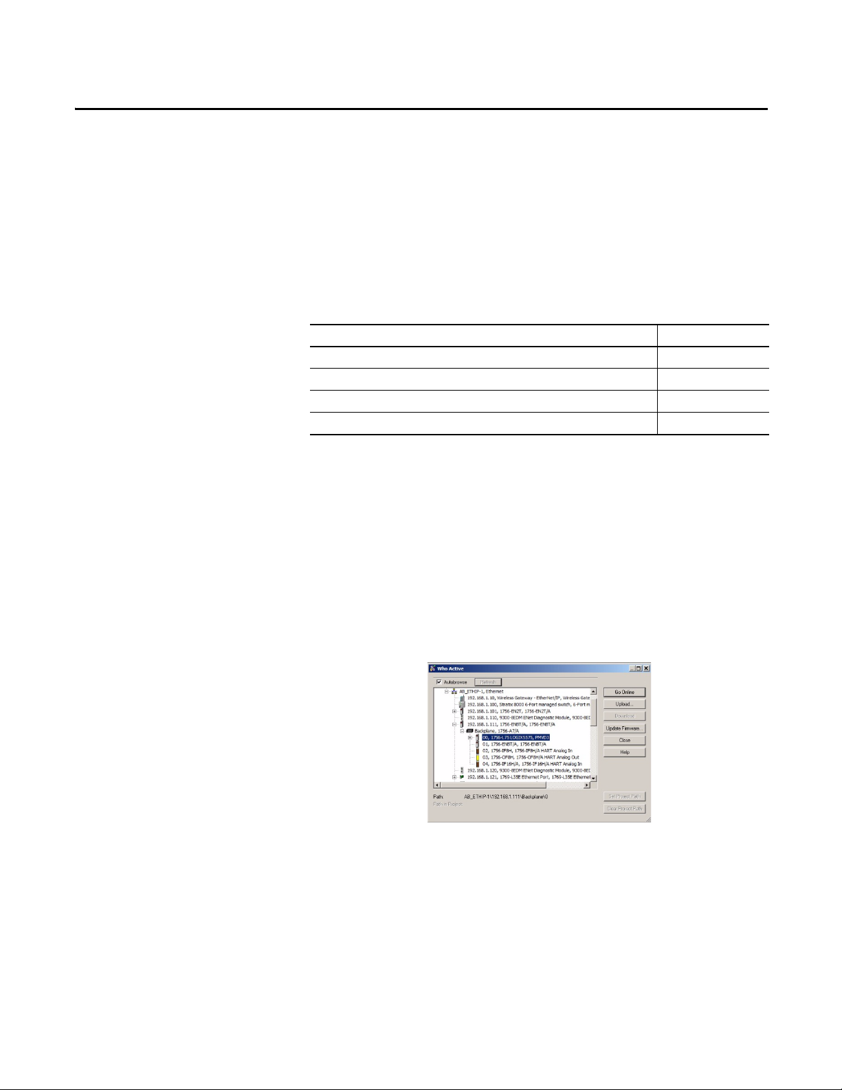
Configure a HART Input Module in a ControlLogix System
In RSLogix 5000 software, you must have a project open with a ControlLogix
controller already configured. Make sure the project path is set to the correct
controller.
Use RSWHO Active in RSLogix 5000 software to verify that the controller,
HART input module, and devices are active.
Rockwell Automation Publication PROCES-UM002A-EN-P - July 2014 21
Page 22
Chapter 2 Configure the HART Device in RSLogix 5000 Programming Software
To configure the I/O module, follow these steps within the configuration tree.
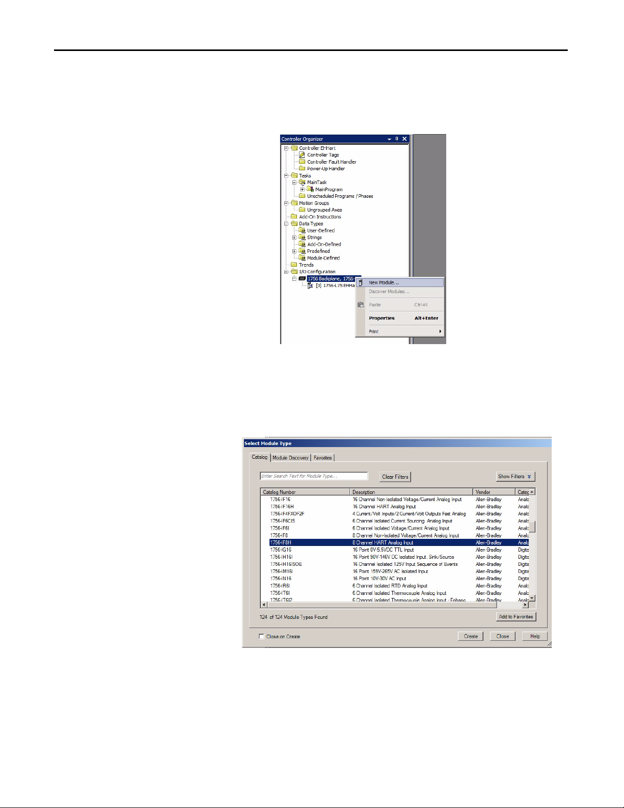
1. From the configuration tree, right click the 1756 backplane and choose
New Module.
If the controller communicates with the I/O module over a network, the
network interfaces must be added to the configuration tree before adding
the I/O module.
2. From the list, select the 1756-IF8H input module.
22 Rockwell Automation Publication PROCES-UM002A-EN-P - July 2014
Page 23
Configure the HART Device in RSLogix 5000 Programming Software Chapter 2
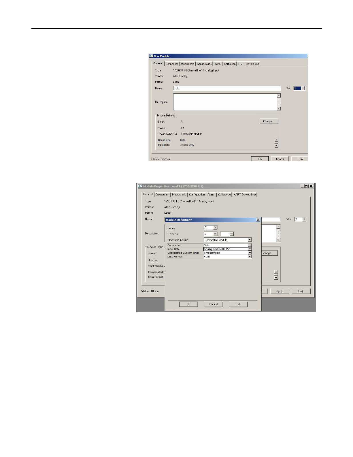
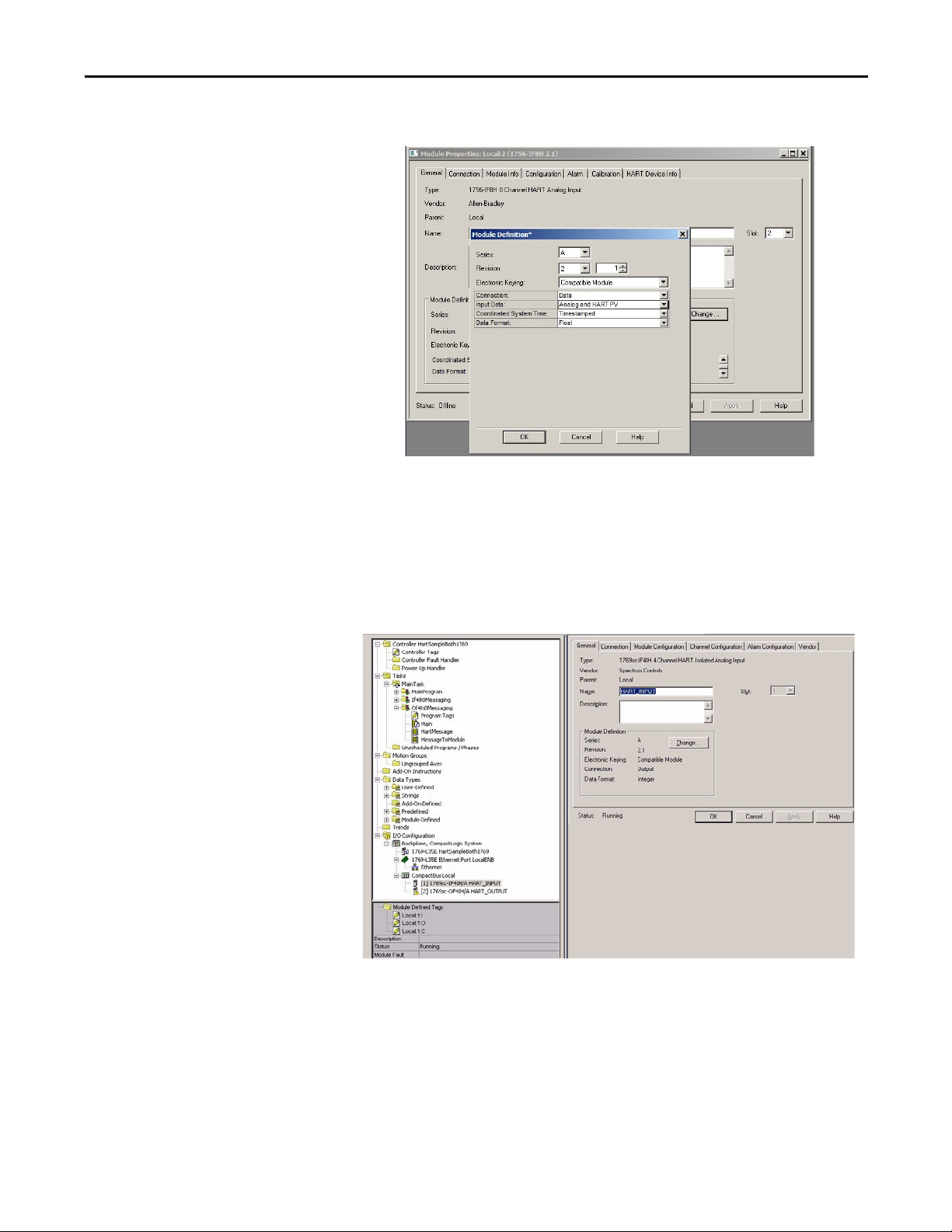
3. On the General tab, enter the configuration information for the module.
4. Click Change.
5. For Input Data, choose Analog and HART PV.
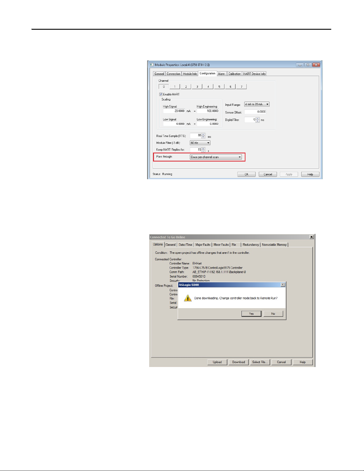
6. On the Configuration tab, enable HART for each channel connected to a
device.
Each channel must be enabled to pass HART data to the controller.
Rockwell Automation Publication PROCES-UM002A-EN-P - July 2014 23
Page 24
Chapter 2 Configure the HART Device in RSLogix 5000 Programming Software
7. On the Configuration tab, for Passthrough, choose Once per channel
scanned.
This passthrough selection is the fastest and best for asset management
software.
8. When complete, click OK.
9. Click Download to go online.
24 Rockwell Automation Publication PROCES-UM002A-EN-P - July 2014
Page 25
Configure the HART Device in RSLogix 5000 Programming Software Chapter 2
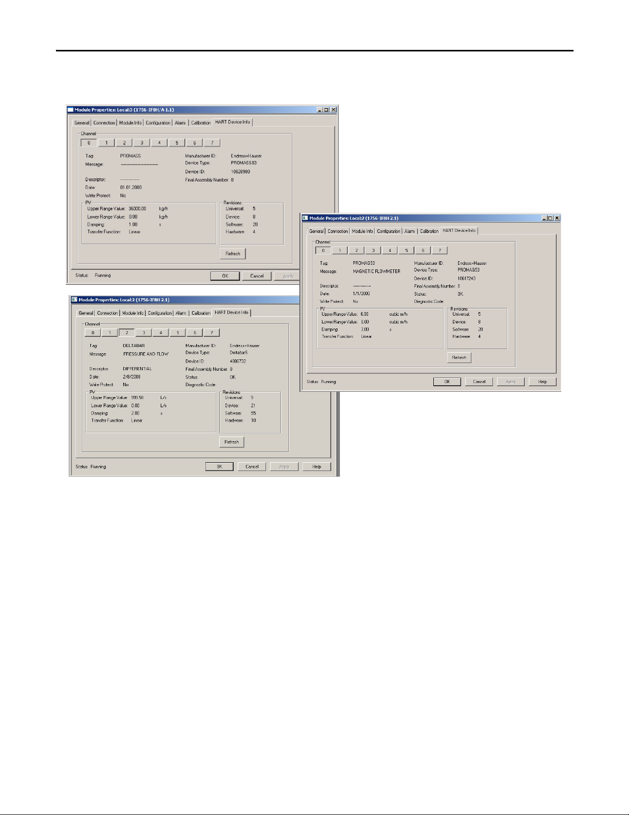
10. From the HART Device Info tab in the HART module properties, verify
that the instrument is connected.
Rockwell Automation Publication PROCES-UM002A-EN-P - July 2014 25
Page 26
Chapter 2 Configure the HART Device in RSLogix 5000 Programming Software
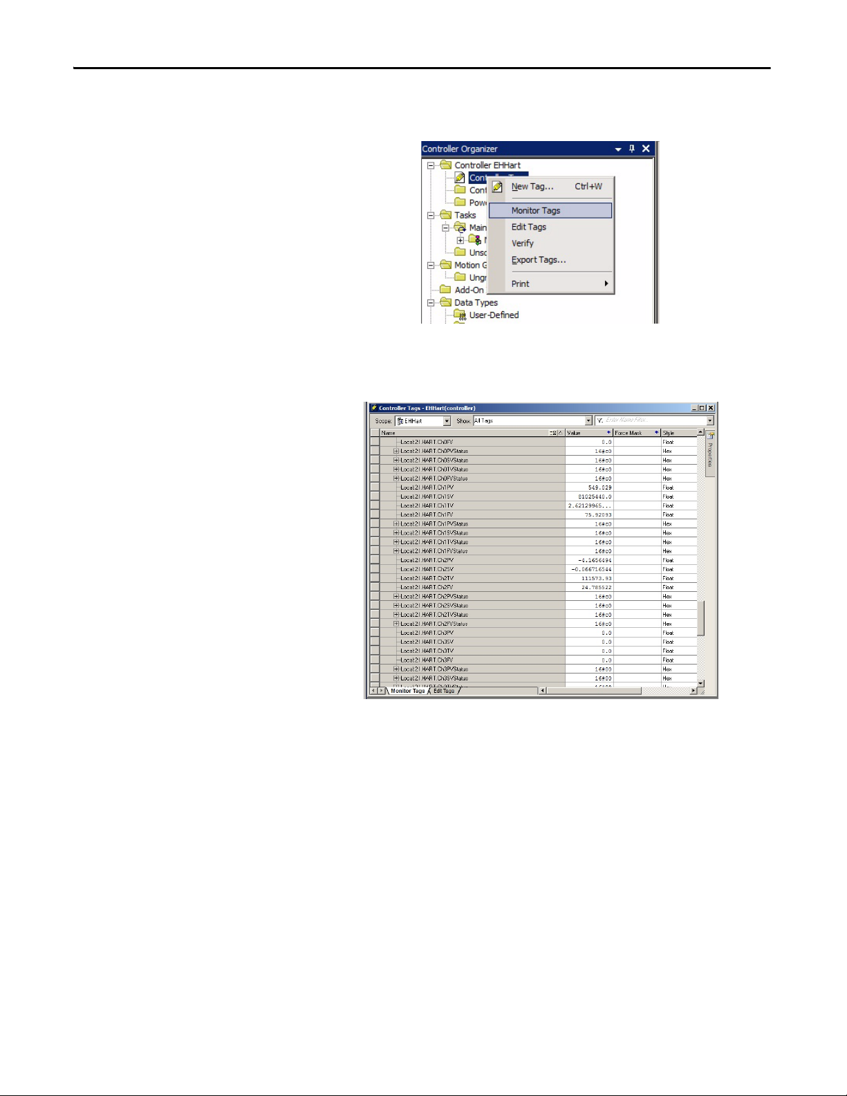
11. Check Controller Tags to verify that the HART instrument is connected
and passing data.
A connected instrument displays values in the PV, SV, TV, and FV fields.
This tag example shows that the HART input module is in slot 6.
26 Rockwell Automation Publication PROCES-UM002A-EN-P - July 2014
Page 27
Configure the HART Device in RSLogix 5000 Programming Software Chapter 2
If HART data is not present, make sure the HART function is enabled.
Configure a HART Input Module in a Compact I/O System
Use RSWHO Active in RSLogix 5000 software to verify that the controller,
HART input module, and devices are active.
This example has a 1769-L35E CompactLogix controller and the Spectrum
1769sc-IF4IH module and uses the Spectrum sample ACD file.
Rockwell Automation Publication PROCES-UM002A-EN-P - July 2014 27
Page 28
Chapter 2 Configure the HART Device in RSLogix 5000 Programming Software
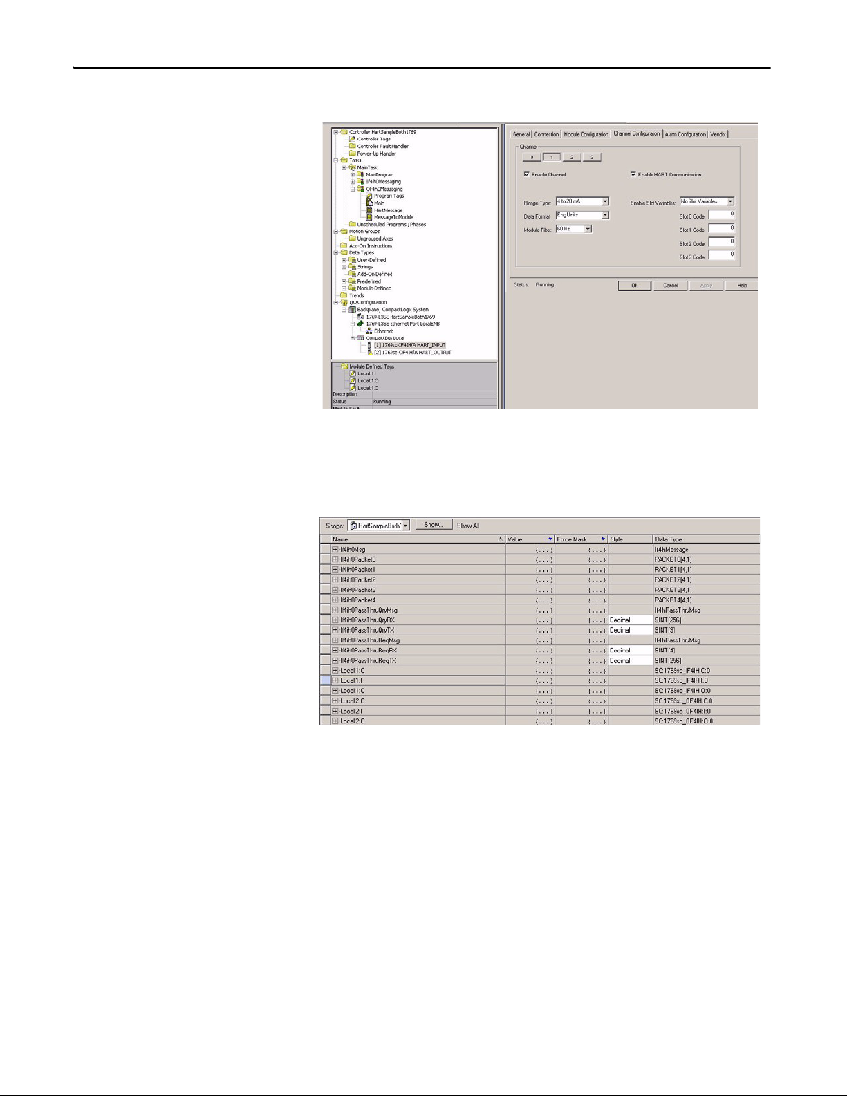
The Spectrum 1769sc-IF4IH is configured as shown.
Make sure that Enable Channel and Enable HART Communication are both
checked.
The Spectrum 1769sc-IF4IH has these controller tags.
28 Rockwell Automation Publication PROCES-UM002A-EN-P - July 2014
Page 29
Configure the HART Device in RSLogix 5000 Programming Software Chapter 2
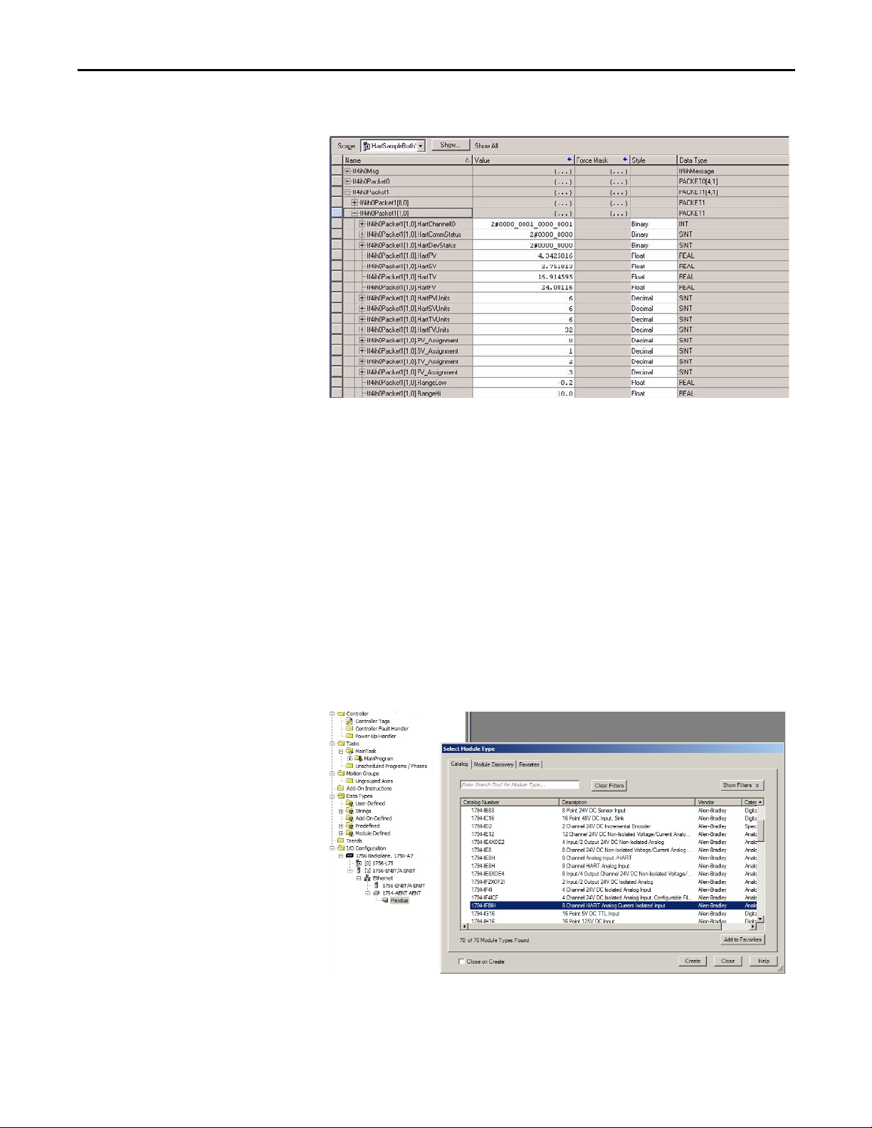
This example shows the PV values from the device mapped to the data structure.
Configure a HART Input Module in a FLEX I/O System
In RSLogix 5000 software, you must have a project open with a controller already
configured. Make sure the project path is set to the correct controller.
Use RSWHO Active in RSLogix 5000 software to verify that the controller,
HART input module, and devices are active.
To configure the I/O module, follow these steps within the configuration tree.
This example assumes you have a 1756-ENBT interface and a 1794-AENT
adapter.
1. From the configuration tree, right click the 1794-AENT adapter and
choose New Module.
2. From the list, select the HART input module and click Create.
Rockwell Automation Publication PROCES-UM002A-EN-P - July 2014 29
Page 30
Chapter 2 Configure the HART Device in RSLogix 5000 Programming Software
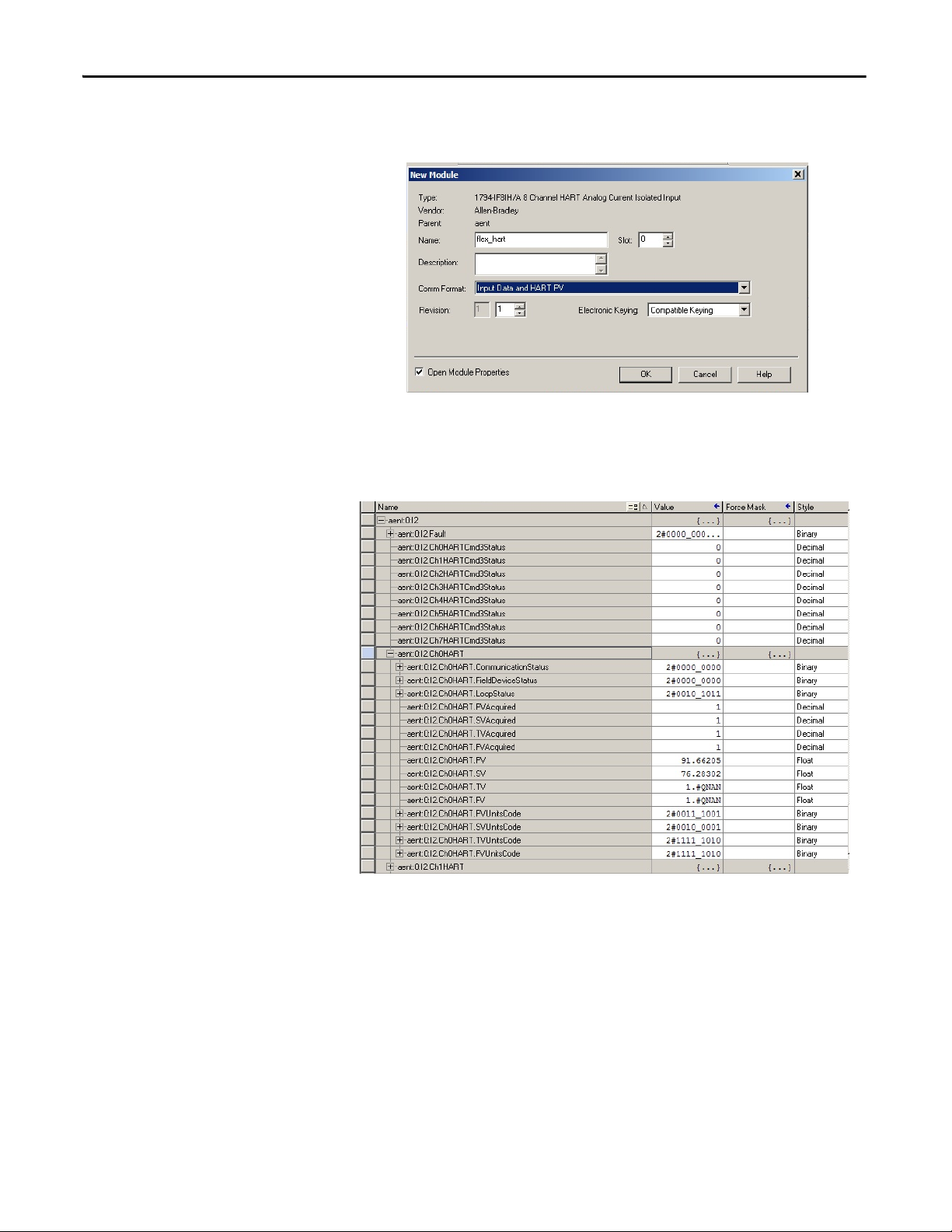
3. Enter the configuration information for the module and choose the
HART communication format.
4. Click OK.
5. Go online and check the controller tags to make sure the device is
connected.
30 Rockwell Automation Publication PROCES-UM002A-EN-P - July 2014
Page 31

Configure the HART Device in RSLogix 5000 Programming Software Chapter 2
Configure a HART Input Module in a POINT I/O System
In RSLogix 5000 software, you must have a project open with a controller already
configured. Make sure the project path is set to the correct controller.
Use RSWHO Active in RSLogix 5000 software to verify that the controller,
HART input module, and devices are active.
To configure the I/O module, follow these steps within the configuration tree.
This example assumes you have a 1756-ENBT interface and a 1734-AENT
adapter.
1. From the configuration tree, right click on the 1734-AENT module and
choose New Module.
Rockwell Automation Publication PROCES-UM002A-EN-P - July 2014 31
Page 32

Chapter 2 Configure the HART Device in RSLogix 5000 Programming Software
2. From the list, select the HART input module and click Create.
3. Enter the configuration information for the module and click Change.
4. Enter additional configuration information and click OK.
5. From the Channel Configuration tab, choose the channel.
32 Rockwell Automation Publication PROCES-UM002A-EN-P - July 2014
Page 33

Configure the HART Device in RSLogix 5000 Programming Software Chapter 2
6. Enable the HART function for each channel required.
7. Click OK.
8. Go Online and check the controller tags to verify operation.
Rockwell Automation Publication PROCES-UM002A-EN-P - July 2014 33
Page 34

Chapter 2 Configure the HART Device in RSLogix 5000 Programming Software
Notes:
34 Rockwell Automation Publication PROCES-UM002A-EN-P - July 2014
Page 35

Chapter 3
IMPORTANT
Configure the HART Device in FactoryTalk AssetCentre Software
Top ic Pag e
Update the DTM Catalog 35
Configure the DTM Network Path 36
Configure a HART Device 44
Configure a FLEX I/O Module 50
FactoryTalk AssetCentre Software is a FDT-based, plant asset management
software tool that you use to configure intelligent field instruments for
Endress+Hauser.
Update the DTM Catalog
Before beginning this process, make sure the DTMs and EDSs have been
downloaded from the vendor websites, imported, and installed.
1. Launch AssetCentre software and open a project.
2. Choose Tools > DTM catalog to update the available DTMs.
Rockwell Automation Publication PROCES-UM002A-EN-P - July 2014 35
Page 36

Chapter 3 Configure the HART Device in FactoryTalk AssetCentre Software
3. Look through the catalog of installed DTMs and look for a green
checkmark on the appropriate DTM.
A yellow triangle indicates that the DTM is found but needs to be
scanned.
Configure the DTM Network Path
4. If necessary, click Scan Now and then verify that the DTMs you installed
exist in the catalog.
5. Close the DTM catalog.
The network path will vary based on your system. In this example the host
personal computer communicates through a 175 backplane.
1. Choose Tasks > DTM Networks.
36 Rockwell Automation Publication PROCES-UM002A-EN-P - July 2014
Page 37

Configure the HART Device in FactoryTalk AssetCentre Software Chapter 3
2. Click on the name of the Host PC network on the tree to the left and then
click Add DTM.
3. Click on the 1756 Chassis DTM.
Rockwell Automation Publication PROCES-UM002A-EN-P - July 2014 37
Page 38

Chapter 3 Configure the HART Device in FactoryTalk AssetCentre Software
The tree should look like the following screen.
4. Select the chassis and click Add DTM
The following screen should appear.
5. Browse to the backplane containing the appropriate controller. and click
OK.
38 Rockwell Automation Publication PROCES-UM002A-EN-P - July 2014
Page 39

Configure the HART Device in FactoryTalk AssetCentre Software Chapter 3
6. Click Select path to autobrowse.
For some I/O it may be necessary to click Open to configure the path.
7. Click Next.
8. Select DTM Networks and view the tree.
9. Select the chassis and click Add DTM.
Rockwell Automation Publication PROCES-UM002A-EN-P - July 2014 39
Page 40

Chapter 3 Configure the HART Device in FactoryTalk AssetCentre Software
10. Select the I/O module.
11. Click OK.
12. Enter the slot number and other configuration data.
40 Rockwell Automation Publication PROCES-UM002A-EN-P - July 2014
Page 41

Configure the HART Device in FactoryTalk AssetCentre Software Chapter 3
13. Click Next.
14. Select the module and click Add DTM.
Rockwell Automation Publication PROCES-UM002A-EN-P - July 2014 41
Page 42

Chapter 3 Configure the HART Device in FactoryTalk AssetCentre Software
15. Select the correct channel and click OK.
Repeat for additional channels with devices.
16. Click Scan network to locate devices.
17. Click OK.
42 Rockwell Automation Publication PROCES-UM002A-EN-P - July 2014
Page 43

Configure the HART Device in FactoryTalk AssetCentre Software Chapter 3
18. Click DTM Info.
19. Make sure the correct DTMS are available and green.
Scan for any required DTMS that appear in yellow.
Rockwell Automation Publication PROCES-UM002A-EN-P - July 2014 43
Page 44

Chapter 3 Configure the HART Device in FactoryTalk AssetCentre Software
Configure a HART Device
1. Right click on the device an select Online.
2. Click Open.
Device information should appear.
3. Click Next.
4. Click Design.
44 Rockwell Automation Publication PROCES-UM002A-EN-P - July 2014
Page 45

Configure the HART Device in FactoryTalk AssetCentre Software Chapter 3
5. Choose Process Area > New.
6. In the Process Area tree, select Instrument.
Rockwell Automation Publication PROCES-UM002A-EN-P - July 2014 45
Page 46

Chapter 3 Configure the HART Device in FactoryTalk AssetCentre Software
7. Enter the name of the device and click OK.
8. Right click on the name of the device you just created and select
Properties.
46 Rockwell Automation Publication PROCES-UM002A-EN-P - July 2014
Page 47

Configure the HART Device in FactoryTalk AssetCentre Software Chapter 3
9. Select DTM Addressing Info and click on the ellipsis.
10. Select the device and click OK.
The device information appears.
Rockwell Automation Publication PROCES-UM002A-EN-P - July 2014 47
Page 48

Chapter 3 Configure the HART Device in FactoryTalk AssetCentre Software
11. Click OK.
12. Right click on the device name and select DTM View.
48 Rockwell Automation Publication PROCES-UM002A-EN-P - July 2014
Page 49

Configure the HART Device in FactoryTalk AssetCentre Software Chapter 3
13. When the device information appears, go online.
14. Select any views desired and save the project.
Rockwell Automation Publication PROCES-UM002A-EN-P - July 2014 49
Page 50

Chapter 3 Configure the HART Device in FactoryTalk AssetCentre Software
Configure a FLEX I/O Module
1. From the DTM Networks tree, select the FLEX rail.
2. Click Add DTM.
3. Select the FLEX I/O module and click OK.
The tree should look similar to this.
50 Rockwell Automation Publication PROCES-UM002A-EN-P - July 2014
Page 51

Configure the HART Device in FactoryTalk AssetCentre Software Chapter 3
4. Select the FLEX rail.
5. Use AutoBrowse to select the path.
Rockwell Automation Publication PROCES-UM002A-EN-P - July 2014 51
Page 52

Chapter 3 Configure the HART Device in FactoryTalk AssetCentre Software
Notes:
52 Rockwell Automation Publication PROCES-UM002A-EN-P - July 2014
Page 53

Chapter 4
IMPORTANT
Configure the HART Device in E+H Fieldcare Software
Top ic Pag e
Configure a HART Input Module and Device 53
Access Instrument Data 56
Additional Functions 58
FieldCare is the Endress+Hauser FDT-based, plant-asset management tool for
configuring intelligent field instruments.
Configure a HART Input Module and Device
1. Start FieldCare and open a new project.
To optimize FieldCare performance, it is recommended that you
verify that the correct DTMs are loaded in the catalog.
Rockwell Automation Publication PROCES-UM002A-EN-P - July 2014 53
Page 54

Chapter 4 Configure the HART Device in E+H Fieldcare Software
2. Choose DTM Catalog > Update.
3. Select desired DTMs and click Move.
If you do not find the desired DTMs, or if the left pane of the dialog box is
empty, click Update. FieldCare software searches for DTMs installed on
your computer.
If necessary, to remove DTMs, select the desired DTMs in the right pane
and click Move.
4. Click OK.
54 Rockwell Automation Publication PROCES-UM002A-EN-P - July 2014
Page 55

Configure the HART Device in E+H Fieldcare Software Chapter 4
5. From the Device Operation/Add Device menu, select the RSLinx 1756
Backplane and click OK.
6. To configure the RSLinx backplane, double-click on the RSLinx
backplane in the left pane.
7. Click Select Path and drill down to the ControlLogix backplane.
Rockwell Automation Publication PROCES-UM002A-EN-P - July 2014 55
Page 56

Chapter 4 Configure the HART Device in E+H Fieldcare Software
8. From the Device Operation/Add Device menu, select the 1756-IF8H/A
module and click OK.
Access Instrument Data
9. To configure the 1756-IF8H module, double-click on the module
backplane in the left pane.
10. Enter the slot number and click the Create Network icon.
11. When prompted, click OK.
The Com DTM now scans the entire HART network behind the multiplexer
and searches for the right DTM.
If the right DTM is installed, the instrument comes up in the Explorer view on
the left side.
If only one DTM is added to the network, the software automatically goes
online. Otherwise a warning occurs that must be confirmed. To switch this
behavior off, in the Fieldcare-context-menu Extras/Options, select After
Scanning within page Scanning.
You can use FieldCare software to access instrument data.
The following examples show a Promass field instrument. The screens vary
depending on the field instrument.
1. In an open FieldCare project, right-click on the instrument in the left pane
and choose Connect.
2. Double-click on the instrument in the left pane.
56 Rockwell Automation Publication PROCES-UM002A-EN-P - July 2014
Page 57

Configure the HART Device in E+H Fieldcare Software Chapter 4
3. In the Online pane, choose Device Data.
4. To view measured values, right-click on the instrument in the left pane and
choose Observe.
Rockwell Automation Publication PROCES-UM002A-EN-P - July 2014 57
Page 58

Chapter 4 Configure the HART Device in E+H Fieldcare Software
Additional Functions
You can use FieldCare software to perform these additional functions:
• Toggle between connected and disconnected modes
• Read from device
• Wri te to de vic e
• Device-specific functions
58 Rockwell Automation Publication PROCES-UM002A-EN-P - July 2014
Page 59

Chapter 5
Visualization
Top ic Pag e
Add-On Instructions 59
Global Object 75
Face pla tes 81
To use the predesigned faceplates to monitor the instrument, HART must be
enabled for the HART input module. FactoryTalk View SE faceplates provide for
visualization of instruments connected to a HART input module. The HART
input module provides the necessary data to the faceplates.
Add-On Instructions
Add-on instructions provide the basis for an object-oriented programming
methodology, where code is encapsulated into pre-validated modules that can be
reused without modification. This lets you create standardized libraries that can
both reduce project development time and provide consistency to reduce
equipment startup and support costs. When using the PlantPAx device
faceplates, you need to use the Add-on Instructions provided in the PlantPAx
Process Object Library. For more information about Add-On Instructions, see
Logix5000 Controllers Add-On Instructions Programming Manual, publication
1756-PM010
The HART IO provides the primary analog process variable, primary HART
process variable, secondary HART process variable, tertiary process variable and
the fourth process variable along with status when HART is enabled.
There are pre-designed Add-On Instructions that exchange data between the
faceplates and the controller. The name of the specific instance of the Add-On
.
Rockwell Automation Publication PROCES-UM002A-EN-P - July 2014 59
Page 60

Chapter 5 Visualization
IMPORTANT
Instruction becomes the link from the actual instrument to the faceplate on the
graphic.
Add-On Instruction Description
I_AB56IF8H Structured input data for each HART 8 channel input module.
The I_AB56IF8H Add-On Instruction collects and organizes data from module parameters and from a module query
that provides extra HART data via a CIP message from the controller to the I/O module.
I_AB56IF16H Structured input data for each HART 16 channel input module.
The I_AB56IF16H Add-On Instruction collects and organizes data from module parameters and from a module query
that provides extra HART data via a CIP message from the controller to the I/O module.
I_AB56FxHChan Structured data for each instrument.
The I_AB56IFxH_Chan Add-On Instruction takes specific data from each channel and point and arranges it for the
P_AIn56H Add-On Instruction. The I_AB56IFxH_Chan Add-On Instruction deciphers and prioritizes the HART
Command 48 diagnostic message and sends the highest priority message (numerically) to the P_AIn56H Add-On
Instruction.
P_AIn56H Send the analog and process variable values from each instrument to one or more faceplates.
The P_AIn56H Add-On Instruction uses embedded P_MODE and P_ALARM Add-On Instructions.
The P_AIn56H Add-On Instruction not only organizes data in a similar fashion as other PlantPAx operator interfaces but
it organizes the data so operators can expect interaction to remain the same throughout the HMI.
The P_AIn_HART Add-On Instruction uses embedded P_MODE and P_ALARM
Add-On Instructions. These embedded Add-On Instructions must already be in
the project before importing the P_AIn_HART Add-On Instruction.
Download the Add-On Instructions
For the latest compatible software information and to download the PlantPAx
Library, see the Product Compatibility and Download Center at
http://www.rockwellautomation.com/rockwellautomation/support
(Log-in required).
.
60 Rockwell Automation Publication PROCES-UM002A-EN-P - July 2014
Page 61

Visualization Chapter 5
Import Add-On Instructions
To use the Add-On Instructions, you import them into a controller project.
Follow these steps for each Add-On Instruction.
1. In the Controller Organizer window, right click on Add-On Instructions
and choose Import Add-On Instruction.
Rockwell Automation Publication PROCES-UM002A-EN-P - July 2014 61
Page 62

Chapter 5 Visualization
2. Select the Add-On Instruction to import from the File Explorer window
and click Import.
3. Click OK in the Import Configuration Window.
62 Rockwell Automation Publication PROCES-UM002A-EN-P - July 2014
Page 63

Visualization Chapter 5
4. Once the import is complete, the Add-On Instructions and any additiona
data types are visible in the Controller Organizer.
Add an Add-On Instruction to a Routine
Follow these steps to add an Add-On Instruction to a routine.
1. Open the routine by double clicking the routine name in the Controller
Organizer.
Rockwell Automation Publication PROCES-UM002A-EN-P - July 2014 63
Page 64

Chapter 5 Visualization
2. Right click in field of the sheet and select Add Element.
3. Browse to the Add-On Instruction folder, select the Add-On Instruction,
and click OK.
Repeat this process for each required Add-On Instruction. Each analog input
module needs one I_AB56IF8H(for 8 channel) or I_AB56IF16H(for 16
channel), one I_AB56IFxH_Chan per HART device, and one P_AIn56H per
device.
64 Rockwell Automation Publication PROCES-UM002A-EN-P - July 2014
Page 65

Visualization Chapter 5
When all the Add-On Instructions are in the routine, connect them as shown
below. Each I_AB56IFxH_Chan connects to one of P_AIn56H.
Configure I_AB56IF8H
Make the following modifications to each I_AB56IF8H Add-On Instruction.
• You must create the backing tag and all of the reference input tags. Follow a
system or naming convention for your application to keep multiple
instances of this Add-On Instruction organized.
• Configure the Ref_Inp tag to point to the location of the Analog HART
Interface module in the chassis.
Rockwell Automation Publication PROCES-UM002A-EN-P - July 2014 65
Page 66

Chapter 5 Visualization
• Configure the Ref_ChanDevInfoMSG tag so the path points to the
Analog HART Interface module in the chassis.
66 Rockwell Automation Publication PROCES-UM002A-EN-P - July 2014
Page 67

Visualization Chapter 5
• Configure the Ref_ModDiagMSG tag so the path points to the Analog
HART Interface module in the chassis.
Configure I_AB56IFxH_Chan
Make the following modifications to the I_AB56IFxH_Chan Add-On
Instruction.
• You must create the backing tag. Follow a system or naming convention for
your application to indicate the channel of the analog input module that it
is referencing.
Rockwell Automation Publication PROCES-UM002A-EN-P - July 2014 67
Page 68

Chapter 5 Visualization
• Configure Ref_ChanData and Ref_ChanDiag to point to the appropriate
array channel position from the tags created in conjunction with
I_AB56IF8H.
Configure P_AIn56H
Make the following modifications to the P_AIN56H Add-On Instruction.
• You must create the backing tag. Follow a system or naming convention for
your application to indicate the channel of the analog input module that it
is referencing.
• Configure Ref_DevInfo to point to the appropriate array channel position
from the tags created in conjunction withI_AB56IF8H.
68 Rockwell Automation Publication PROCES-UM002A-EN-P - July 2014
Page 69

Visualization Chapter 5
• Configure the Ref_FaultTable and Ref_EUTable tags. These tables
provide the fault codes and engineering units for the device. You can create
your own table with device-specific codes and descriptions, or there are
generic tables available in the sample projects contained within the
PlantPAx Process Object Library.
Rockwell Automation Publication PROCES-UM002A-EN-P - July 2014 69
Page 70

Chapter 5 Visualization
Link an Add-On Instruction to Graphics in FactoryTalk View SE Software
This graphic displays how the P_AIn56H works within an HMI.
• Pre-designed AOIs provide a two-way exchange of data between the
faceplates and the ControlLogix controller.
• FactoryTalk View SE faceplates provide visualization of instruments
connected to the network interface
• By clicking the pushbutton with a value on a screen the faceplate is linked
to the P_AIn56H AOI via a tag name and the faceplate values get
populated with the AOIs data.
70 Rockwell Automation Publication PROCES-UM002A-EN-P - July 2014
Page 71

Visualization Chapter 5
Add Library Components to an HMI Application
Follow these steps (in this exact order) to add library components.
1. Import the images.
Import all the .BMP and .PNG files. The .BMP and .PNG files must be
imported separately.
a. Right click on Images and choose Add Component Into Application.
b. Select all of the .PNG image files from the Process Objects Library and
click Open.
Rockwell Automation Publication PROCES-UM002A-EN-P - July 2014 71
Page 72

Chapter 5 Visualization
You will need to change the path to the image folder and the file type to
.PNG.
2. Import the global objects.
Import the .GGFX files.
a. Right click on Global Objects and choose Add Component Into
Application.
72 Rockwell Automation Publication PROCES-UM002A-EN-P - July 2014
Page 73

b. Select all of the .ggfx files and click Open.
Visualization Chapter 5
3. Import the displays.
a. Right click on Displays and select Add Component Into Application.
Rockwell Automation Publication PROCES-UM002A-EN-P - July 2014 73
Page 74

Chapter 5 Visualization
b. Select the Faceplate and Quick file associated with the P_AIn56H and
click Open.
Import the Macro.
4.
a. Right click on Macro and select Add Component Into Application.
b. Select the NavToObject.mcr file and click Open.
74 Rockwell Automation Publication PROCES-UM002A-EN-P - July 2014
Page 75

Visualization Chapter 5
Fac toryTa lk Vie w SE Display
Add-On Instructions in a
function block routine.
Click on global object.
Global object
IMPORTANT
Global Object
A global object links the tag name to the faceplate, provides a touch area for the
faceplate to be launched from, and displays the process variables and alarms.
A unique global object and faceplates are available for each field instrument
due to the display of instrument-specific diagnostic information.
Add Global Objects to a Display
Follow these steps too add global objects.
1. Open the (RA-BAS) P_AIn Graphics Library by expanding the Global
Objects and double-clicking on the library.
Rockwell Automation Publication PROCES-UM002A-EN-P - July 2014 75
Page 76

Chapter 5 Visualization
2. Click on the object that best suites your display to highlight it, right click,
and select Copy.
3. Go to the display and paste the global object into the display.
76 Rockwell Automation Publication PROCES-UM002A-EN-P - July 2014
Page 77

Visualization Chapter 5
Configure Tags
Follow these steps to configure tags for a global object.
1. Right click on the global object and select Global Object Parameter
Va l u e s .
You need to configure the first, second, and fifth parameters.
Rockwell Automation Publication PROCES-UM002A-EN-P - July 2014 77
Page 78

Chapter 5 Visualization
2. Click the Tag browse button for the first parameter Object
Ta g .
3. Click the Refresh All Folders button.
78 Rockwell Automation Publication PROCES-UM002A-EN-P - July 2014
Page 79

Visualization Chapter 5
4. Expand the shortcut for the project controller and then click Online.
5. Expand and scroll down the Online menu so you can select the tag for the
P_AIn56H AOI instance you created and click OK.
Rockwell Automation Publication PROCES-UM002A-EN-P - July 2014 79
Page 80

Chapter 5 Visualization
You might have to expand the program if the tag is program scoped.
6. Select the same tag for the second parameter as had been selected for the
first.
Return to the Global Object Parameter Values window, edit the value field
for the second parameter, and leave just the path to the tag.
7. Click on the value field for the fifth parameter and enter the value 2.
This value causes a smaller, ‘Quick’ faceplate to appear, which can be
expanded to the full faceplate.
80 Rockwell Automation Publication PROCES-UM002A-EN-P - July 2014
Page 81

These parameter values should appear.
8. Click OK.
Visualization Chapter 5
Faceplates
9. Click the Save button at the top, left corner of the screen.
The FactoryTalk View SE generic display provides a graphical representation of
the instrument based on the information contained within each Add-On
Instruction. Navigation buttons at the top of the faceplate change the
information displayed. Status displays show information using a bar graph,
numeric values, and a trend display. Other displays show specific alarms and
warning indication.
Here are some examples of predesigned faceplates.
Rockwell Automation Publication PROCES-UM002A-EN-P - July 2014 81
Page 82

Chapter 5 Visualization
IMPORTANT
A unique global object and faceplates are available for each field instrument
due to the display of instrument-specific diagnostic information.
The faceplates provide the following information:
• Tag name from instrument
• Description from instrument
• Engineering units from instrument
• Typical analog process values (PV)
• Analog fault status (channel fault, broken wire, module fault)
• HART PV (first, second, third)
• HART PV fault status (first, second, third, fourth)
• HART PV range (minimum and maximum)
• HART command 48 diagnostic information
Configure the faceplates to provide the following:
• Mode (such as operator or program)
• High-high, high, low, and low-low alarms
• Over-range and under-range alarms
• Alarm delay
• Alarm hysteresis
82 Rockwell Automation Publication PROCES-UM002A-EN-P - July 2014
Page 83

Promag 53 Electromagnetic Flowmeter
Top ic Pag e
Connect a Promag 53 Flowmeter 84
Configure a Promag 53 Flowmeter 86
Component Catalog Number Details
Promag 53 electromagnetic flowmeter 53P15-EL081AA0BAAA Firmware revision 2.01
Appendix A
Promag measuring instruments are electromagnetic flowmeters for bidirectional
measurement of liquids. They provide cost-effective flow measurement with a
high degree of accuracy for a wide range of process conditions.
The tried-and-tested Promag sensor offers the following:
• No pressure loss
• No sensitivity to vibrations
• Simple installation and commissioning
Faraday's law of induction states that a voltage is induced in a conductor moving
in a magnetic field. In electromagnetic measuring, the flowing medium
corresponds to the moving conductor. The induced voltage is proportional to the
flow velocity and is detected by two measuring electrodes and transmitted to the
amplifier. Flow volume is computed on the basis of the pipe's diameter. The
constant magnetic field is generated by a switched direct current of alternating
polarity.
Rockwell Automation Publication PROCES-UM002A-EN-P - July 2014 83
Page 84

Appendix A Promag 53 Electromagnetic Flowmeter
Item Description
Ue Induced voltage, Ue = B· L· v
B Magnetic induction (magnetic field)
LElectrode gap
VFlow velocity
Q Volume flow,
A Pipe cross-section
I Current strength
Q = A· v
Signal Details
Current Output Active/passive selectable, galvanically isolated
Pulse/Frequency Output Active/passive selectable, galvanically isolated (Ex i version: only passive)
Connect a Promag 53 Flowmeter
Measured Variable
Flow rate (proportional to induced voltage)
Signals from Instrument to Control System
• Active: 0/4...20 mA, RL < 700 Ω (HART: RL ≥ 250 Ω)
• Passive: 4...20 mA, operating voltage VS 18...30V DC, Ri <
• Active: 24 V DC, 25 mA (max. 250 mA during 20 ms), RL > 100 Ω
• Passive: open collector, 30V DC, 250 mA
• Frequency output: full scale frequency 2...10000 Hz (fmax = 12500 Hz), EEx-ia: 2...5000 Hz; on/off ratio 1:1;
pulse width max. 10 s
• Pulse output: pulse value and pulse polarity adjustable, pulse width configurable (0.05...2000 ms)
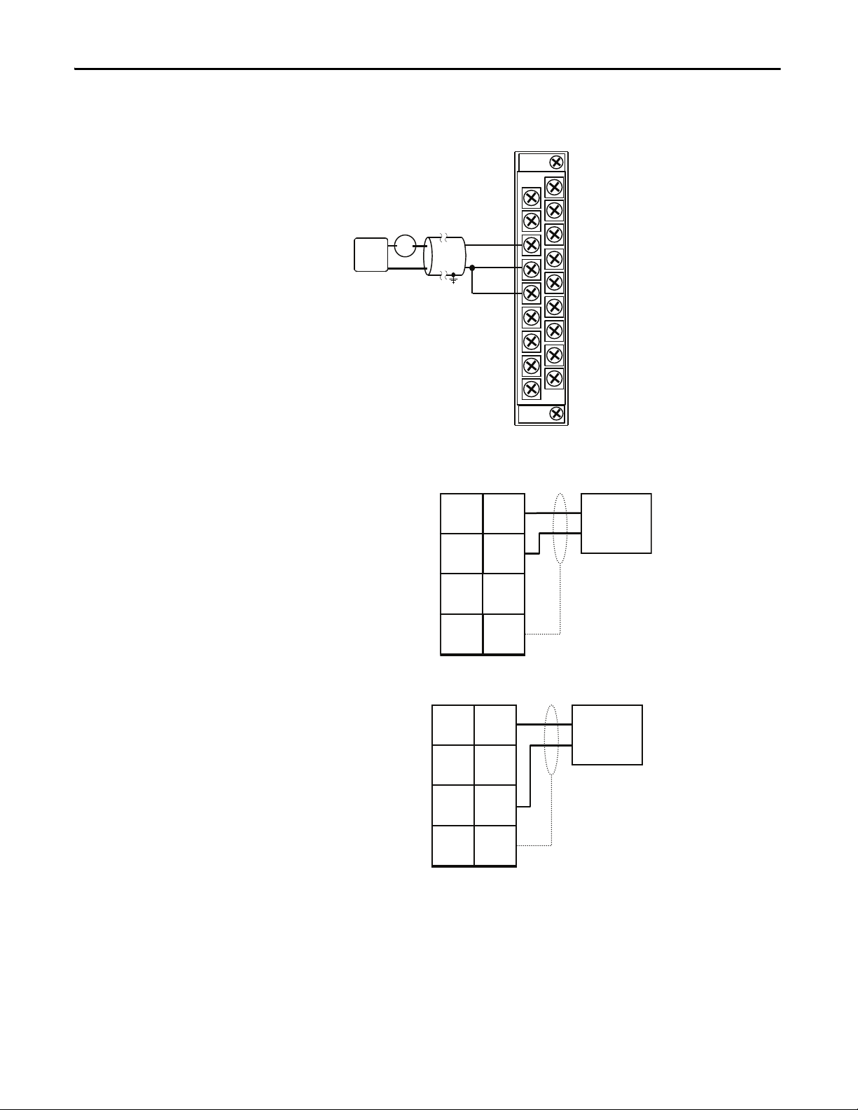
Use a 4-wire connection to the HART input module.
1. Remove the cover of the connection compartment (f ) from the
transmitter housing.
150 Ω
2. Feed the power supply cable (a) and signal cables (b) through the
appropriate cable entries.
84 Rockwell Automation Publication PROCES-UM002A-EN-P - July 2014
Page 85

Promag 53 Electromagnetic Flowmeter Appendix A
b
b
c
d
a
a
2
1
–27
–25
–23
–21
+26
+24
+22
+20
L1 (L+)
N (L-)
g
f
e
3. Connect the HART communications cable to the HART connector in
the order white (+), black (-) on pins 26, 27 of the connector.
4. For AC powered instruments, connect the AC cable to the power
connector in the order ground (as shown), black (pin1), white (pin2).
5. Screw the cover of the connection compartment (f ) firmly onto the
transmitter housing.
Item Description
a Cable for power supply: 85...260 V AC, 20...55 V AC, 16...62 V DC
• Terminal No. 1: L1 for AC, L+ for DC
• Terminal No. 2: N for AC, L- for DC
b Signal cable: Terminal Nos. 20-27
c Ground terminal for protective conductor
d Ground terminal for signal cable shield
e Service adapter for connec ting service interface FXA 193 (FieldCheck, FieldCare)
f Cover of the connection compartment
gSecuring clamp
Rockwell Automation Publication PROCES-UM002A-EN-P - July 2014 85
Page 86

Appendix A Promag 53 Electromagnetic Flowmeter
➀
➂
➁
➃
➄
➅
Esc
E
+
-
XXX.XXX.XX
F
O
F
Commission
Language
Defaults
Quick Setup
HOME-POSITION
QS
Volume
Mass
Quit
Configure another unit?
NOYES
Unit
Unit
Volume Flow
Totalizer
Unit
Density
Value
Density
Unit
Unit
Mass flow
Totalizer
Selection
System units
1002
2000
0402
3001
0420
0700
0400
3001
B
Frequency Pulse
Current Output Freq.-/ Pulse Output
Quit
Assign
Current
Current
Span
Value
0_4 mA
Value
20 mA
Measuring
Mode
Time
Constant
Failsafe
Mode
Failsafe
Mode
Failsafe
Mode
4000
4001
4002
4003
4004
4005
4006
Operation
Mode
4200
Selection
Output type
Assign
Frequency
End
Value Freq.
Value
F low
Value
F high
Measuring
Mode
Output
Signal
Time
Constant
4201
4203
4204
4205
4206
4207
4208
4209
Pulse
Value
Pulse
Width
Measuring
Mode
Output
Signal
4221
4222
4223
4225
4226
4227
Assign
Pulse
Configure another Output?
Autom. Configuration of Display?
NO
NO
YES
Pulsating Flow
Carrying out the
Quick Setup
Pulsating Flow
Carrying out the
Quick Setup
Batching
Automatic parameterization
of the display
Inquiry: another
Quick Setup?
NOYES
Batching
Configure a Promag 53 Flowmeter
You can configure the device via the local display and menus on the instrument.
On the local display of the field instrument, use the Quick Setup menus to
configure instrument parameters.
86 Rockwell Automation Publication PROCES-UM002A-EN-P - July 2014
Page 87

Pulsating Flow
➀
➁
➂
➃
Esc
E
+
-
XXX.XXX.XX
F
O
F
Quick Setup
B
Frequency Pulse
Current Output Freq.-/ Pulse Output
Quit
YES NO
Quit
Measuring
Mode
Time
Constant
4004
4005
Operation
Mode
4200
Measuring
Mode
Time
Constant
4206
4208
Measuring
Mode
4225
HOME-POSITION
Selection
Output
Selection
Totalizer
Totalizer 3 Totalizer 2 Totalizer 1
Alarm
Delay
Assign
On-value
Off-value
Pressure
LF-Cutoff
LF-Cutoff
LF-Cutoff
pulse suppr.
8005
6400
6402
6403
6404
Quit Quick Setup
Puls. Flow
Display
Damping
1003
2002
Totalizer
Mode
(DAC)
3002
Totalizer
Mode
(DAB)
3002
Totalizer
Mode
(DAA)
3002
Configure another
Output?
YES
NO
QS
Configure another
Totalizer?
Promag 53 Electromagnetic Flowmeter Appendix A
Rockwell Automation Publication PROCES-UM002A-EN-P - July 2014 87
Page 88

Appendix A Promag 53 Electromagnetic Flowmeter
Batching
88 Rockwell Automation Publication PROCES-UM002A-EN-P - July 2014
Page 89

Proline t-mass 65 Thermal Flowmeter
Top ic Pag e
Connect a Proline t-mass 65 Flowmeter 91
Configure a Proline t-mass 65 Flowmeter 92
Component Catalog Number Details
Proline t-mass 65 thermal mass flowmeter 65I-20AA0AD1A1BABA Firmware revision 1.00
Appendix B
The Proline t-mass thermal flowmeter provides direct measurement of gas mass
flow and temperature as an output.
The t-mass sensor offers the following:
• Negligible pressure drop or loss.
• Wide turndown of up to 100:1.
• Insertion version can be programmed for circular pipe or rectangular
ducting installation.
• Each device individually calibrated and delivered with a traceable
certificate.
• Can be calibrated with flow conditioner on request.
• Optional cold tap device for insertion allowing ease of removal/
replacement for low pressure and non-toxic gas applications.
Rockwell Automation Publication PROCES-UM002A-EN-P - July 2014 89
Page 90

Appendix B Proline t-mass 65 Thermal Flowmeter
IMPORTANT
The thermal principle operates by monitoring the cooling effect of a gas stream as
it passes over a heated transducer (PT100). Gas flowing through the sensing
section passes over two PT 100 RTD transducers, one of which is used
conventionally as a temperature sensing device, whilst the other is used as a
heater. The temperature sensor monitors the actual process values whilst the
heater is maintained at a constant differential temperature above this by varying
the power consumed by the sensor. The greater the mass flow, the greater the
cooling effect and power required in order to maintain the differential
temperature. The measured heater power is therefore a measure of the gas mass
flow rate.
Measured Variables
• Mass flow
• Gas temperature
Signals from Instrument to Control System
Signal Details
Current Output Active/passive selectable, galvanically isolated
• Active: 0/4...20 mA, RL < 700 Ω (at HART: RL ≥ 250 Ω)
• Passive: 4...20 mA, Ri ≥ 150 Ω, Umax = 30V DC
Pulse/Frequenc y Output • Active: 24 V DC, 25 mA (max. 250 mA during 20 msec), RL > 100 Ω
• Passive, open collector, 30V DC, 250 mA, galvanically isolated
• Frequency output: full scale frequency 2...1000 Hz (fmax = 1250 Hz), on/off ratio 1:1, pulse width max. 2s, time
constant selectable (0.0...100.0s)
• Pulse output: pulse value and pulse polarity selectable, pulse width adjustable (0.5. ..2000 ms)
If the current output is used as a temperature output, please observe the
information for Class B according to EN 6075.
90 Rockwell Automation Publication PROCES-UM002A-EN-P - July 2014
Page 91

Proline t-mass 65 Thermal Flowmeter Appendix B
b
b
c
d
a
a
2
1
–27
–25
–23
–21
+26
+24
+22
+20
L1 (L+)
N (L-)
g
f
e
Connect a Proline t-mass 65 Flowmeter
Use a 4-wire connection to the HART input module.
1. Unscrew the connection compartment cover (f) from the transmitter
housing.
2. Feed the power supply cable (a) and the signal cable (b) through the
appropriate cable entries.
3. Connect the HART communications cable to the HART connector in
the order white (+), black (-) on pins 26, 27 of the connector.
4. For AC powered instruments, connect the AC cable to the power
connector in the order ground (as shown), black (pin 1), white (pin 2).
5. Screw the cover of the connection compartment (f ) back onto the
transmitter housing.
Item Description
a Cable for power supply: 85...260 V AC, 20...55 V AC, 16...62 V DC
• Terminal No. 1: L1 for AC, L+ for DC
• Terminal No. 2: N for AC, L- for DC
b Signal cable: Terminals Nos. 20-27
c Ground terminal for protective ear th
d Ground terminal for signal cable shield
e Service adapter for connecting service interface FXA193 (FieldCheck, FieldCare)
f Cover of the connection compartment
g Securing clamp
Rockwell Automation Publication PROCES-UM002A-EN-P - July 2014 91
Page 92

Appendix B Proline t-mass 65 Thermal Flowmeter
+
+
E
+
E
n
o
s
Esc
E
+
-
XXX.XXX.XX
p
r
m
q
Yes
Yes
Yes
No
No
No
Configure another system unit ?
Current output n Pulse/ output nFreq.
Selection output type
Automatic configuration of display ?
Quit
Assign
Current output
Current span
Value 0/4 mA
Value 20 mA
Time constant
Time constant
Failsafe mode
Failsafe mode
Failsafe mode
Assign
Freq. output
End value freq.
Value f Low
Value f High
Output signal
Assign
Pulse output
Pulse value
Pulse width
Output signal
Operation Mode
Frequency Pulse
Automatic parameterization of the display
Corr. Vol. flow
Pressure
Mass flow
Density
Selection system units
Temperature
Quit
Unit
Corr. Vol. flow
Unit
Mass flow
Unit
Density
Unit
Length
Unit
Totalizer
Unit
Pressure
Unit
Totalizer
Language
Pre-setting
Quick Setup
HOME-POSITION
QS
Commission
Configure another output ?
Length
Unit
Temperature
Selection pre-settings
Reference
Temperature
Reference
Pressure
Process
Pressure
Selection pipe type
Pipe type
Circular Rectangular
Internal
Diameter
Internal
Height
Internal
Width
Failsafe value
Delivery settings Actual settings
Configure a Proline t-mass 65 Flowmeter
You can configure the device via the local display and menus on the instrument.
On the local display of the field instrument, use the Quick Setup menus to
configure instrument parameters.
92 Rockwell Automation Publication PROCES-UM002A-EN-P - July 2014
Page 93

Promass 83 Coriolis Mass Flowmeter
321
A
B
A
B
A
B
Top ic Pag e
Connect a Promass 83 Flowmeter 94
Configure a Promass 83 Flowmeter 96
Component Catalog Number Details
Promass 83 mass flowmeter 83E08-AAASAAAAABANB Firmware revision 2.02
Appendix C
Promass measuring instruments make it possible to simultaneously record several
process variables (mass/density/temperature) for various process conditions
during measuring operation. Promass sensors, tried and tested in over 100,000
applications, offer the following:
• Multivariable flow measurement in compact design
• Insensitivity to vibrations thanks to balanced two-tube measuring system
• Immunity from external piping forces due to robust design
• Easy installation without taking inlet and outlet runs into consideration
The measuring principle is based on the controlled generation of Coriolis forces.
In the sensor, two parallel measuring tubes containing flowing fluid oscillate in
antiphase, acting like a tuning fork. The Coriolis forces produced at the
measuring tubes cause a phase shift in the tube oscillations. At zero flow, in other
words when the fluid is at a standstill, the two tubes oscillate in phase (1). Mass
flow causes deceleration of the oscillation at the inlet of the tubes (2) and
acceleration at the outlet (3).
Rockwell Automation Publication PROCES-UM002A-EN-P - July 2014 93
Page 94

Appendix C Promass 83 Coriolis Mass Flowmeter
The phase difference (A-B) increases with increasing mass flow. Electrodynamic
sensors register the tube oscillations at the inlet and outlet. System balance is
ensured by the antiphase oscillation of the two measuring tubes. The measuring
principle operates independently of temperature, pressure, viscosity, conductivity
and flow profile.
Measured Variables
• Mass flow (proportional to the phase difference between two sensors
mounted on the measuring tube to register a phase shift in the oscillation)
• Volume flow (calculated from mass flow and fluid density. The density is
proportional to the resonance frequency of the measuring tubes.)
• Measuring tube temperature (by temperature sensors) for calculatory
compensation of temperature effects
• Density by monitoring the tube frequency is directly proportional to
medium density
• Totalized flow (application dependent using pulse output)
Signal Details
Current Signal Active/passive selectable, galvanically isolated.
Pulse/Frequency Signal Active/passive selectable, galvanically isolated.
Connect a Promass 83 Flowmeter
Signals from Instrument to Control System
• Active: 0/4...20 mA, R
• Passive: 4...20 mA; supply voltage U
• Active: 24 V DC, 25 mA (max. 250 mA during 20 ms), RL > 100 Ω
• Passive, open collector, 30V DC, 250 mA
• Frequency output: full scale frequency 2...10000 Hz (f
• Pulse output: pulse value and pulse polarity selec table, pulse width configurable (0.05...2000 ms)
Use a 4-wire connection to the HART input module.
Supply 100V AC power to the field instrument. Connect instrument
communication to the HART terminals. The sensor was preinstalled at the
factory.
1. Remove the cover of the connection compartment (f ) from the
transmitter housing.
2. Feed the power supply cable (a) and signal cables (b) through the
appropriate cable entries
< 700 Ω (for HART: RL ≥ 250 Ω)
L
18...30V DC; Ri ≥ 150 Ω
S
= 12500 Hz), on/off ratio 1:1, pulse width max. 2 s
max
3. Connect the HART communications cable to the HART connector in
the order white (+), black (-) on pins 26, 27 of the connector.
4. For AC powered instruments, connect the AC cable to the power
connector in the order ground (as shown), black (pin 1), white (pin 2).
94 Rockwell Automation Publication PROCES-UM002A-EN-P - July 2014
Page 95

Promass 83 Coriolis Mass Flowmeter Appendix C
5. Screw the cover of the connection compartment (g) firmly onto the
transmitter housing.
f
b
a
g
e
N (L-)
L1 (L+)
–27
+26
–25
+24
–23
+22
–21
+20
2
1
Item Description
a Cable for power supply: 85...260 V AC, 20...55 V AC, 16...62 V DC
bSignal cable
c Ground terminal for protective conductor
d Ground terminal for signal cable shield
e Ser vice adapter for connecting service interface FXA 193 (Fieldcheck, FieldCare)
f Cover of the connection compartment
gSecuring clamp
b
d
c
a
Rockwell Automation Publication PROCES-UM002A-EN-P - July 2014 95
Page 96

Appendix C Promass 83 Coriolis Mass Flowmeter
+
+
E
+
E
n
o
s
Esc
E
+
-
XXX.XXX.XX
p
r
m
q
Yes
Yes
Yes
No
No
No
Configure another system unit ?
Current output n Pulse/ output nFreq.
Selection output type
Automatic configuration of display ?
Quit
Assign
Current output
Current span
Value 0/4 mA
Value 20 mA
Time constant
Time constant
Failsafe mode
Failsafe mode
Failsafe mode
Assign
Freq. output
End value freq.
Value f Low
Value f High
Output signal
Assign
Pulse output
Pulse value
Pulse width
Output signal
Operation Mode
Frequency Pulse
Automatic parameterization of the display
Corr. Vol. flow
Pressure
Mass flow
Density
Selection system units
Temperature
Quit
Unit
Corr. Vol. flow
Unit
Mass flow
Unit
Density
Unit
Length
Unit
Totalizer
Unit
Pressure
Unit
Totalizer
Language
Pre-setting
Quick Setup
HOME-POSITION
QS
Commission
Configure another output ?
Length
Unit
Temperature
Selection pre-settings
Reference
Temperature
Reference
Pressure
Process
Pressure
Selection pipe type
Pipe type
Circular Rectangular
Internal
Diameter
Internal
Height
Internal
Width
Failsafe value
Delivery settings Actual settings
Configure a Promass 83 Flowmeter
You can configure the device via the local display and menus on the instrument.
On the local display of the field instrument, use the Quick Setup menus to
configure instrument parameters.
96 Rockwell Automation Publication PROCES-UM002A-EN-P - July 2014
Page 97

Prowirl 73 Flowmeter
Top ic Pag e
Connect a Prowirl 73 Flowmeter 99
Configure a Prowirl 73 Flowmeter 102
Component Catalog Number Details
Prowirl 73 vortex flow meter 73W15-SK4AA1AAB4AA Firmware revision 1.03
Appendix D
The Prowirl measurement instrument provides the following:
• Complete saturated steam or liquid-mass measuring point in one single
device
• Calculation of the mass flow from the measured variables volume flow and
temperature in the integrated flow computer
• External pressure value read-in for superheated steam and gas applications
(optional)
• External temperature value read-in for delta heat measurement (optional)
The robust Prowirl sensor, tried and tested in over 100,000 applications, offers
the following:
• High resistance to:
– vibrations (over 1g in all axes)
– temperature shocks (>150 K/s)
– contaminated media
– water hammer
• No maintenance, no moving parts, no zero-point drift ("lifetime"
calibration)
• Software initial settings save time and costs
Rockwell Automation Publication PROCES-UM002A-EN-P - July 2014 97
Page 98

Appendix D Prowirl 73 Flowmeter
v
Vortex meters work on the principle of the Karman vortex street. When fluid
flows past a bluff body, vortices are alternately formed on both sides with
opposite directions of rotation. These vortices each generate a local low pressure.
The pressure fluctuations are recorded by the sensor and converted to electrical
pulses. The vortices develop very regularly within the permitted application
limits of the device. Therefore, the frequency of vortex shedding is proportional
to the volume flow.
The K-factor is used as the proportional constant:
K-Factor =
Pulses
Unit Volume [dm
3
]
Measured Variables
• Volumetric flow (volume flow) is proportional to the frequency of vortex
shedding after the bluff body.
• The temperature can be output directly and is used to calculate the mass
flow for example.
• The measured process variables volume flow, temperature or the calculated
process variables mass flow, heat flow or corrected volume flow can be
output as the output variables.
98 Rockwell Automation Publication PROCES-UM002A-EN-P - July 2014
Page 99

Signals from Instrument to Control System
IMPORTANT
Signal Details
Current Output • 4 to 20 mA with HART
• Full scale value and time constant (0 to 100 s) can be set
Frequency Output, Pulse/Status Output Frequency output (optional): open collector, passive, galvanically isolated
• Non-Ex, Ex d/XP version:
– U
max = 36 V, with 15 mA current limiting, Ri = 500 Ω
• Ex i/IS and Ex n version:
– Umax = 30 V, with 15 mA current limiting, Ri = 500 Ω
Frequency output:
• End frequency 0 to 1000 Hz (fmax = 1250 Hz)
Pulse output:
• Pulse value and polarity can be selected (5 to 2000 ms)
• Pulse width can be configured (0.005 to 2 s)
• Pulse frequency max. 100 Hz
Status output:
• Can be configured for error messages or flow values, temperature values, pressure limit values
Vor tex f requ enc y:
• Direct output of unscaled vortex pulses 0.5 to 2850 Hz (e.g. for connecting to an RMC621 flow computer)
• Pulse ratio 1:1
Prowirl 73 Flowmeter Appendix D
Connect a Prowirl 73 Flowmeter
Use a 2-wire connection to the HART input module.
1. Unscrew the cover (a) of the electronics compartment from the
transmitter housing.
2. Remove the display module (b) from the retaining rails (c) and refit onto
right retaining rail with the left side (this secures the display module).
3. Loosen screw (d) of the cover of the connection compartment and fold
down the cover.
4. Push the cable for the power supply/current output through the cable
gland (e).
Optional: Push the cable for the pulse output through the cable gland (f ).
5. Tighten the cable glands (e/f).
6. Pull the terminal connector (g) out of the transmitter housing and
connect the cable for the power supply/current output (see wiring
diagram).
Optional: Pull terminal connector (h) out of the transmitter housing and
connect the cable for the pulse output (see wiring diagram).
The terminal connectors (g/h) are pluggable, i.e. they can be plugged out of
the transmitter housing to connect the cables.
Rockwell Automation Publication PROCES-UM002A-EN-P - July 2014 99
Page 100

Appendix D Prowirl 73 Flowmeter
IMPORTANT
e
f
g
h
d
a
c
b
d
7. Plug the terminal connectors (g/h) into the transmitter housing.
The connectors are coded so you cannot mix them up.
8. Fold up the cover of the connection compartment and tighten the screws
(d).
9. Remove the display module (b) and fit on the retaining rails (c).
10. Screw the cover of the electronics compartment (a) onto the transmitter
housing.
11. Only remote version: Secure the ground cable to the ground terminal (see
wiring diagram, c).
Item Description
a Cover of electronics compartment
b Display module
c Retaining rail for display module
d Connection compartment cover threaded connection
e Cable gland for power supply/current output cable
f Cable gland for pulse output cable (optional)
g Terminal connector for power supply/current output
h Terminal connector for pulse output (optional)
100 Rockwell Automation Publication PROCES-UM002A-EN-P - July 2014
 Loading...