

Page 1
Installation Instructions
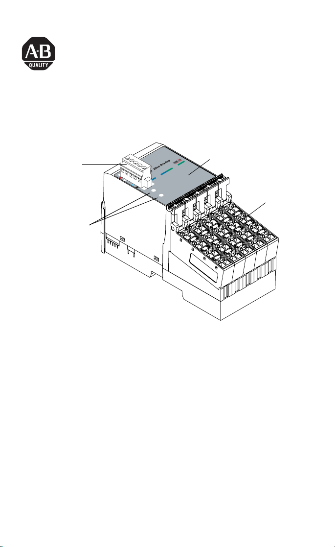
POINTBlock dc 8 Input/8 Output Module
(Cat. No. 1734D-IB8XOB8E and -IB8XOB8ES)
I/O Status
DeviceNet
Connector
Module
Status
Network
Status
Outputs
0
1
4
Inputs
5
0
6
1
2
9
-
3
0
3
6
-
0
1
DeviceNet Node
Setting Switches
(1s and 10s)
This 1734D input/output module is a DIN-rail mounted device with
an integrated DeviceNet communication interface, 8 inputs and 8
outputs, removable terminations, and a PointBus expansion port.The
expansion port allows you to add up to a maximum of 12 additional
POINT I/O modules.
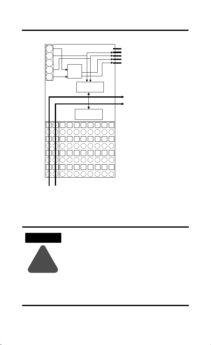
The module includes a non-isolated DeviceNet communication
interface. The 24V dc from the DeviceNet connection powers a
non-isolated dc/dc converter that generates +5V dc which powers the
POINTBlock electronics and connects to the PointBus port to power
the expansion I/O electronics.
Indicators
4
5
6
7
2
3
7
Remote
Termination
Blocks
The 1734D-IB8XOB8E uses cage-clamp terminations, and the
1734D-IB8XOB8ES uses spring-clamp terminations.
POINTBlock is a trademark
of Rockwell Automation1 Publication 1734-IN020A-EN-P - July 2001
Page 2
2 POINTBlock dc 8 Input/8 Output Module
!
DeviceNet
Connector
Power
Connections
12/24V dc
24
CH
SH
CL
RT
24V
to 5V
Microprocessor
En
CH
PointBus Expansion Port
CL
5V
(allows expansion of up to
GND
12 POINT I/O modules)
Field Bus
Connector
I/O Circuits
I/O Connections
41971
ATTENTION
Whatever field power you supply is connected to
the internal field-power bus. For example, if
120V ac is applied to the power connections,
there will be 120V ac applied to the modules
through the internal field-power bus.
POINT I/O modules to the right of the module
will also have that internal power bus voltage
applied, unless you use a 1734-FPD to interrupt
and change the field power-bus voltage.
Publication 1734-IN020A-EN-P - July 2001
Page 3
POINTBlock dc 8 Input/8 Output Module 3
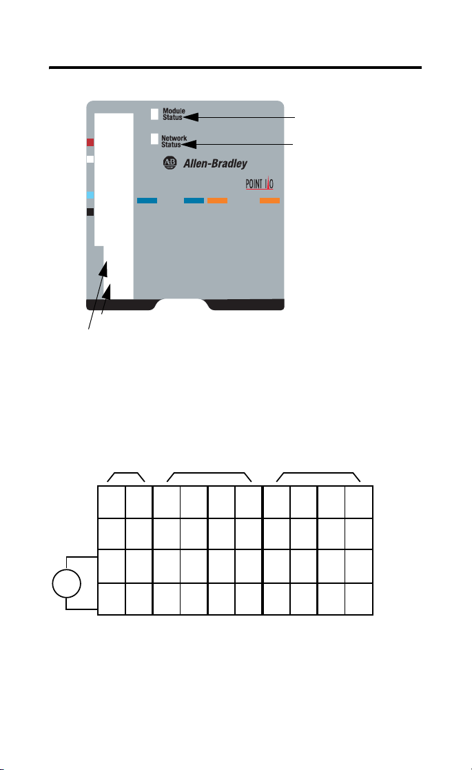
Module Status
Network Status
10-60
Inputs
0
4
1
5
2
6
0-9
3
7
Outputs
0
1
2
3
4
I/O status
5
6
7
1’s Node Address Rotary Switch
10’s Node Address Rotary Switch
42004
To set the node address, set the combination of 1’s and 10’s to
correspond to the required address. (For example, for 61, set
the 10’s switch to 6 and the 1’s switch to 1.)
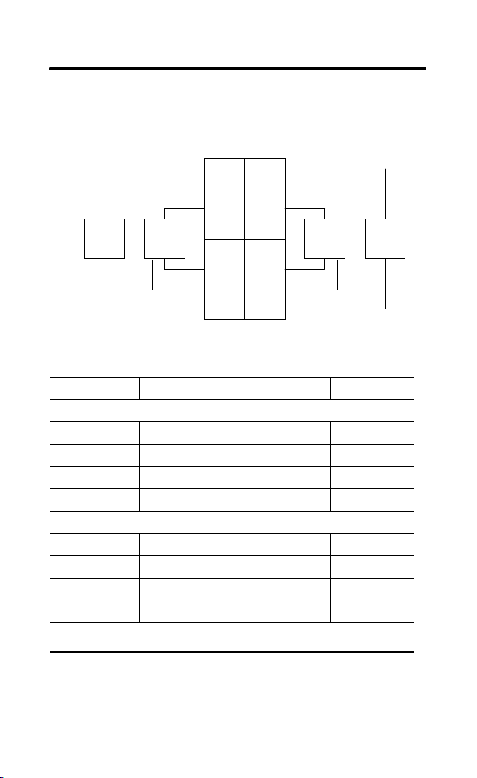
Wiring the 8 Input/8 Output Module
12/24V dc
Power
V dc
Field
Power
01
NC
NC
23
NC
NC
45
Cin
Cin
67
Vin
Vin
RTB 0 RTB 1 RTB 2 RTB 3 RTB 4
Inputs Outputs
01
0
23
2
45
C
67
V
1
3
C
V
01
4
5
23
6
7
45
C
C
67
V
V
01
0
1
23
2
3
45
C
C
67
C
C
This supply will be connected to the internal power bus.
NC = No Connection Chas Gnd = Chassis Ground
C = Common V = Supply
01
4
5
23
6
7
45
C
C
67
C
C
42064
Publication 1734-IN020A-EN-P - July 2001
Page 4
4 POINTBlock dc 8 Input/8 Output Module
Input Wiring
Sink Input
01
In 0 In 1
3-wire2-wire
Prox
2
In 2
4
C
In 3
C
3
Prox ProxProx
5
7
41967
V = 12/24V dc
6
VV
C = Common
Channel Input Terminal Common Voltage
Remote Termination Block 1
0 0 4 6
1 1 5 7
2 2 4 6
3 3 5 7
Remote Termination Block 2
4 0 4 6
5 1 5 7
6 2 4 6
7 3 5 7
Connect common on 3-wire proximity switches.
12/24V dc is supplied through the internal power bus.
Note: When connecting more than 1 wire in a te rmination point, make sure
that both wires are the same gauge and type.
Publication 1734-IN020A-EN-P - July 2001
Page 5

Output Wiring
POINTBlock dc 8 Input/8 Output Module 5
0
Out 0 Out 1
2
Out 3Out 2
Load Load
V = 12/24V dc, C = Common
Field power is supplied from internal power bus
45
CC
6
CC
Output Terminal Common Terminal Power
Remote Termination Block 3
Channel 0 0 4
Channel 1 1 5
Channel 2 2 6
Channel 3 3 7
Remote Termination Block 4
Channel 4 0 4
Channel 5 1 5
Channel 6 2 6
Channel 7 3 7
Module power is supplied from the internal power bus.
1
3
7
Load
Load
RTB3 shown
42015
Note: When connecting more than 1 wire in a te rmination point, make sure
that both wires are the same gauge and type.
Outputs are electronically protected to 0.75A. Module outputs are
selectable for latched mode or auto-reset mode. (Latched/auto reset is set
by module, not by individual channel.) Each channel is assigned a bit in the
data table to indicate the faulte d conditio n. Outputs in th e latched mode can
only be reset with a user command t o t he module.
Publication 1734-IN020A-EN-P - July 2001
Page 6

6 POINTBlock dc 8 Input/8 Output Module
Latch Mode Functionality
State Indication Error Bit
Off Dark 0
On Yellow 0
Faulted/On Red 1
Faulted/Off Flashing Red 1
To reset an output, the reset bit for the output can be set, or the output bit
must be cycled off/on.
Auto Retry Mode Functionality
State Indication Error Bit
Off Dark 0
On Yellow 0
Faulted/On Red 1
Faulted/Off Flashing Red 1
In auto retry, the output will recover once the fault is removed.
DeviceNet Connector Wiring
Red
DeviceNet
connection
Publication 1734-IN020A-EN-P - July 2001
White
Bare
Blue
Black
+V
CAN - High
Shield
CAN - Low
-V
42132
Page 7

POINTBlock dc 8 Input/8 Output Module 7
C-UL and UL Hazardous Location Approval
C-UL and UL certifies products for general use as well as for use in
hazardous locations. Actual C-UL and UL certification is
indicated by the product label as shown below, and not by
statements in any user documentation .
Example of the
C-UL and UL
certification
product label:
To comply with C-UL and UL certification for use in hazardous
locations, th e following information becomes a part of the p roduct
literature for this C-UL and UL-certified industrial con trol product.
• Thi s equipment is suitable f or use in Class I, Divisio n 2,
Groups A, B, C, D, or non-hazardous loc ations only.
• The products having the appropriate C-UL and UL markings
(that is, Class I, Division 2, Groups A, B , C, D) are certified f or
use in other equ ipment where the suitabilit y of combination
(that is, appl ication or use) is de termined by the C -UL and UL
or the local inspe ction office having jurisdic tion
Important: Due to the mod ular nature of a prog rammable control
Temperature code rating:
LISTED
CUS
system, the product with the highest temperatur e rating
determines th e overall temperature c ode rating of a
programmable control s ystem in a Class I, Division 2,
location. The temperature code rating is marked on the
product label a s shown.
CUS
Look for temper ature
code rating here.
The following warnings apply to prod ucts having C-UL and U L
certification for u se in hazardous locations.
WARNING: Explosion Hazard
• Substitution of components may impair s uitability for
Class I, Division 2.
• Do not repl ace components unl ess power has been
switched off or the area is known to be non-hazardous.
• Do not disconnect equipment unless power has been
switched off or the area is known to be non-hazardous.
• Do not disconnect connectors unless power has been
switched off or the area is known to be non-hazardous.
Secure any user-supp lied connectors that mate to
external cir cuits on this equipme nt by using screws,
sliding latches, threaded connectors, or other means
such that any connection can withstand a 15 Newton
(3.4 lb.) sepa rating force applied f or a minimum of one
minute.
C-UL and UL lo go is a registered trad emark of the Underwrit ers
Laboratorie s.
LISTED
CL I, DIV 2
GP A,B,C,D
TEMP
CL I, DIV 2
GP A,B,C,D
TEMP
Approbation d’utilisation dans des
environnements dangereux par la C-UL/UL
La C-UL/UL certi fie des produits pour une utilisat ion générale au ssi bien
que pour une ut ilisation en environnement s dangereux. La
certification C-UL/UL en vigueur est indiquée par l'étiquette
produit et non par des ind ications dans la documentation utilisateur.
Exemple d'étiq uette de
certification d'un produit
par la C-UL/UL :
Pour satisfaire à la certification C-UL/UL en environnements dangereux,
les informati ons suivantes font part ie intégrante de la doc umentation
des produits de commande industrielle certifiés.
• Cet équipemen t ne convient qu’à une utilisa tion en
environnemen ts de Classe I, Divisio n 2,
Groupes A, B , C, D ou non dangereux .
• Les produits portant le marquage C-UL/UL approprié
(c'est-à-dire Classe I, Division 2, Groupes A, B, C, D) sont
certifiés pour u ne utilisation avec d'aut res équipements, les
combinaisons d’applications et d’uti lisations étant déterm inées
par la C-UL/UL o u le bureau local d'inspection qualifié.
Important: De par la nature modulaire des systèmes de commande
programmables, le produit ayant le code de température le
plus élevé détermine le code de température global du
système dans un environnement de Classe I, Division 2. Le
code de température est indiqué sur l'étiquette produit.
Code de température :
Les avertissem ents suivant s s'appliquent au x produits aya nt la certificat ion
C-UL/UL pour u ne utilisation en enviro nnements dangereux .
AVERTISSEMENT : Risque d'explosion
• La substitution de composants peut rendre ce matériel inadapté à
une utilisatio n en environnements de
Classe I, Division 2.
• Couper le c ourant ou s'assurer qu e l’environnement est classé non
dangereux avant de remplacer des composants.
• Couper le co urant ou s’assure r que l’environneme nt est classé non
dangereux avant de débrancher l'équipement.
• Couper le c ourant ou s'assurer qu e l’environnement est classé non
dangereux avant de débrancher les connecteurs. Fixer tous les
connecteurs fournis par l'utilisateur pour se brancher aux circuits
externes de ce t équipement à l 'aide de vis, loquets couliss ants,
connecteurs filetés ou autres, de sorte que les connexions
résistent à u ne force de séparat ion de 15 Newtons (1,5 kg - 3,4 lb.)
appliquée pendant au moins une minute.
• S'assurer qu e l'environnement es t classé non dangereu x avant de
changer les piles.
Les sigles C- UL et UL sont des marqu es déposées de la Unde rwriters
Laboratori es.
LISTED
CUS
LISTED
CUS
Le code de température
est indiqué ici.
CL I, DIV 2
GP A,B,C,D
TEMP
CL I, DIV 2
GP A,B,C,D
TEMP
Publication 1734-IN020A-EN-P - July 2001
Page 8

8 POINTBlock dc 8 Input/8 Output Module
Specifications - 1734D-IB8XOB8E, -IB8XOB8ES
Input Specifications - IEC 1+ 24V dc Input Compliant
ON-State Voltage Range 10V dc min
24V dc nominal
28.8V dc max
ON-State Current 2.5mA min
6.3mA nominal @ 24V dc
7.6mA max
OFF-State Voltage 5V dc max
OFF-State Current 1.5mA min
Input Impedance 4.7K Ω max (3.6K Ω nominal
Input Filter Time
OFF to ON
ON to OFF
0.5ms hardware + (0 - 65ms selectable)
0.5ms hardware + (0 - 65ms selectable)
Output Specifications
ON-State Voltage Range 10V dc min
24V dc nominal
28.8V dc max
ON-State Voltage Drop 0.2V max @ 0.75A
ON-State Current 0.7A max (electronically protected)
OFF-State Voltage 1.5V dc max
General Specifications
Pointbus Output Current 1A max @ 5V dc output power
DeviceNet Current 95mA maximum for POINTBlock
350mA for maximum with expansion of
12 POINT I/O modules
Number of POINT I/O
12 maximum at expansion port
Expansion Modules
Isolation Voltage 1250Vrms or 2121V dc for 1s between user power
and DeviceNet
Indicators 1 red/ green module status indicator
1 red/green network status indicator
16 I/O status indicators (8 input/8 output)
Power Dissipation 2.0W maximum @ 24V dc
Power Consumption 8.2W maximum @ 24V dc
Field Power Bus
Supply Voltage
Voltage Range
Supply Current
24V dc nominal
10-28.8V dc
10A max
Publication 1734-IN020A-EN-P - July 2001
Page 9

POINTBlock dc 8 Input/8 Output Module 9
Dimensions Inches
(Millimeters)
Environmental Conditions
Operational Temperature
Storage Temperature
Relative Humidity
Shock Operating
Non-operating
Vibration
Conductors Wire Size
Category
Terminal Base Screw
3.00H x 2.36W x 5.25L
(76.2 Hx 60.0W x 133.4L)
-20 to +55oC (-4 to +131oF)
-40 to 85oC (-40 to 185oF)
5 to 95% noncondensing
30g peak acceleration, 11(±1)ms pulse width
50g peak acceleration, 11(±1)ms pulse width
Tested 5g @ 10-500Hz per IEC 68-2-6
14 AWG (2.5mm2) - 22 AWG (0.25mm2) solid or
stranded max
3/64 inch (1.2mm) insulation max
1
2
5-7 pound-inches (0.5-0.6 Nm)
Tor qu e
Field Wiring Terminations
DeviceNet
1 - Black Wire -V
2 - Blue Wire CAN Low
3 - Bare Wire Drain
4 - White Wire CAN High
5 - Red Wire +V
Field Power Supply 0 - No Connection 1 - No Connection
2 - No Connection 3 - No Connection
4 - Common 5 - Common
6 - Supply 7 - Supply
Mass 12.02 oz/340.77 grams
Agency Certification
(when product is marked)
• C-UL Listed
• C-UL Class I, Division 2 Groups A, B, C and D
certified
• UL listed
• CE marked for all applicable directives
• C-Tick marked for all applicable acts
1 Use this conductor category information for planning conductor routing. Refer to publication
1770-4.1, “Industrial Automation Wiring and Grounding Guidelines for Noise Immunity.”
Publication 1734-IN020A-EN-P - July 2001
Page 10

10 POINTBlock dc 8 Input/8 Output Module
Publication 1734-IN020A-EN-P - July 2001
Page 11

POINTBlock dc 8 Input/8 Output Module 11
Publication 1734-IN020A-EN-P - July 2001
Page 12

Publication 1734-IN020A-EN-P - July 2001 PN 957236-87
© 2001 Rockwell International Corporation. Printed in USA
 Loading...