

Page 1
Installation Instructions
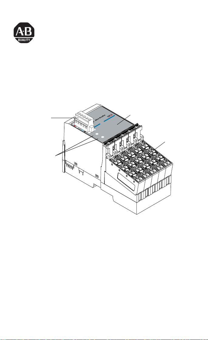
POINTBlock ac 16 Input Module
(Cat. No. 1734D-IA16 and -IA16S)
I/O Status
DeviceNet
Connector
DeviceNet Node
Setting Switches
(1s and 10s)
Module
Status
Network
Status
0-9
12
8
Inputs
9
4
5
0
6
1
7
2
3
10-63
Indicators
13
14
15
10
11
Remote
Termination
Blocks
This 1734D input module is a DIN-rail mounted device with an
integrated DeviceNet communication interface, 16 ac inputs,
removable terminations, and a PointBus expansion port. The
expansion port allows you to add up to 12 additional POINT I/O
modules.
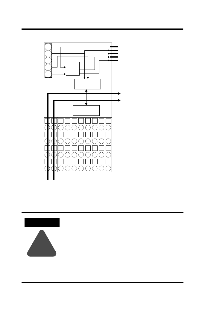
The module includes a non-isolated DeviceNet communication
interface. The 24V dc from the DeviceNet connection powers a
non-isolated dc/dc converter that generates +5V dc which powers the
POINTBlock electronics and connects to the PointBus port to power
the expansion I/O electronics.
The 1734D-IA16 uses cage-clamp terminations, and the 1734D-IA16S
uses spring-clamp terminations.
POINTBlock and POINT I/O are trademarks
of Rockwell Automation1 Publication 1734D-IN001A-EN-P - May 2001
Page 2
2 POINTBlock ac 16 Input Module
ATTENTION
!
Simplified Schematic of POINTBlock
24
DeviceNet
Connector
CH
SH
CL
RT
24V
to 5V
Microprocessor
I/O Circuits
En
CH
PointBus Expansion Port
CL
5V
(allows expansion of up to
GND
12 POINT I/O modules)
Field Bus
Connector
Power
Connections
120V ac
Publication 1734D-IN001A-EN-P - May 2001
I/O Connections
41971
Whatever field power you supply is connected
to the internal field-power bus. For example, if
120V ac is applied to the power connections,
there will be 120V ac applied to the modules
through the internal field-power bus.
POINT I/O modules to the right of this module
will have this internal power bus voltage
applied, unless you use a 1734-FPD to interrupt
and change the field power-bus voltage.
Page 3
POINTBlock ac 16 Input Module 3
ATTENTION
!
ATTENTION
!
POINTBlock is designed to be grounded through
the DIN rail to chassis ground. To assure proper
grounding of POINTBlock and POINT I/O
adapters and terminal bases to chassis ground, the
recommended DIN rail material is zinc-plated,
yellow-chromated steel. Mount POINTBlock,
POINT I/O adapters and terminal bases only to
zinc-plated, yellow-chromated steel.
Installing the POINTBlock 16 Input Module
To install the 16 Input module on the DIN rail, proceed as follows:
1. Position the block module vertically above the DIN rail.
2. Press down firmly to install the module on the DIN rail. (The
locking mechanism will lock the module to the DIN rail.)
Do not discard the end cap. Use this end cap to
cover the exposed interconnections on the last
mounting base/block module on the DIN rail.
Failure to do so could result in equipment
damage or injury from electric shock.
If installing a replacement POINTBlock module to an existing system:
1. To remove the block module from the DIN rail, pull up on the
RTB removal handles to remove the terminal blocks.
2. Use a small bladed screwdriver to rotate the orange DIN rail
locking screw to a vertical position. This releases the locking
mechanism.
3. Lift straight up to remove.
4. Position the replacement block module vertically above the
DIN rail.
Publication 1734D-IN001A-EN-P - May 2001
Page 4
4 POINTBlock ac 16 Input Module
5. Slide the block module down allowing the interlocking side
pieces to engage the adjacent module/adapter.
6. Press firmly to seat the block module on the DIN rail. The
module locking mechanism will snap into place.
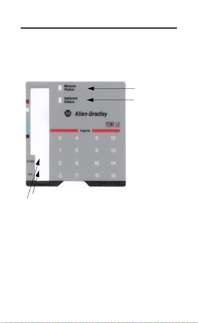
Setting the Node Address
Module Status
Network Status
I/O status
R
1’s Node Address Rotary Switch
10’s Node Address Rotary Switch
To set the node address, set the combination of 1’s and 10’s to
correspond to the required address. (For example, for 61, set the 10’s
switch to 6 and the 1’s switch to 1.)
Publication 1734D-IN001A-EN-P - May 2001
Page 5

Wiring the 16 ac Input Module
Field Power Inputs
POINTBlock ac 16 Input Module 5
1
3
L2
L1
01
4
5
23
6
7
45
L2
L2
67
L1
L1
120V ac
Power
V ac
NCNC0
L2 in
L1in
01
23
2
45
L2
67
L1
01
NC
23
NC
45
L2 in
67
L1in
RTB 0 RTB 1 RTB 2 RTB 3 RTB 4
This supply will be connected to the internal power bus.
NC = No Connection Chas Gnd = Chassis Ground
L2/N = AC Return/Neutral L1 = AC Power
Input Wiring
RTB 1
01
In 0 In 1
2
In 2
Prox
4
6
In 3
L2
L1 L1
L2
01
8
23
10
45
L2
67
L1
3
5
7
01
9
23
11
45
L2
67
L1
12
13
14
15
L2
L2
L1
L1
42064IB
Prox
L1 = 120V ac
Repeat for RTB 2, 3 and 4
41967ac
L2 = Return
Note: When connecting more than 1 wire in a termination point,
make sure that both wires are the same gauge and type.
Publication 1734D-IN001A-EN-P - May 2001
Page 6

6 POINTBlock ac 16 Input Module
Channel Input Terminal Return Voltage
Remote Termination Block 0
Field Power Block No connections to terminals 0, 1, 2, 3 and 4
Vin (L1) 6 and/or 7
Return (L2/N) 4 and/or 5
Remote Termination Block 1
00 6
11 7
22 6
33 7
Remote Termination Block 2
40 6
51 7
62 6
73 7
Remote Termination Block 3
80 6
91 7
10 2 6
11 3 7
Remote Termination Block 4
12 0 6
13 1 7
14 2 6
15 3 7
120V ac is supplied through the internal power bus.
Note: When connecting more than 1 wire in a termination point,
make sure that both wires are the same gauge and type.
Publication 1734D-IN001A-EN-P - May 2001
Page 7

DeviceNet Connector Wiring
POINTBlock ac 16 Input Module 7
+V
CAN - High
Shield
CAN - Low
-V
42132
DeviceNet
connection
Red
White
Bare
Blue
Black
Communicating with Your Module
I/O messages are sent to (consumed) and received from (produced)
the POINTBlock I/O modules. These messages are mapped into the
processor’s memory. This POINTBlock I/O input module produces 2
bytes of input data (scanner Rx). It does not consume I/O data
(scanner Tx).
Default Data for the 1734D-IA16
15 14 13 12 11 10 9876543210
Produces
Consumes
Where: I0 = channel 0, I1 = channel 1; 0 = off, 1 = on
I15 I14 I13 I12 I11 I10 I9 I8 I7 I6 I5 I4 I3 I2 I1 I0
(Rx)
(Tx)
No consumed data
Publication 1734D-IN001A-EN-P - May 2001
Page 8

8 POINTBlock ac 16 Input Module
CUS
e
Safety Approvals
C-UL and UL Hazardous Location Approval
C-UL and UL cer tifies products for ge neral use as well as for use in
hazardous locations. Actual C-UL and UL certification is indicated
by the product label as shown below, and not by statements in an y
user documentat ion.
Example of the C -UL
and UL certificat ion
product label:
CL I, DIV 2
GP A,B,C,D
TEMP
Approbation d’utilisation dans des
environnements dangereux par la C-UL and UL
La C-UL and UL certi fie des produits pour une utili sation générale aussi
bien que pour une utilisation en environ nements dangereux. La
certification C -UL and UL en vigueur est indiquée pa r l'étiquette produit
et non par des indications dans la docum entation utilisateur.
Exemple d'étiq uette de
certification d'un
produit par la C-UL and
UL :
LISTED
To comply with C-UL and UL ce rtification for use in hazardous locations,
the following infor mation becomes a part of the produ ct literature for
this C-UL and UL-certified industrial constrol product.
• This equipmen t is suitable for use in Class I, Division 2, Groups
A, B, C, D, or no n-hazardous location s only.
• The produc ts having the appropria te C-UL and UL markin gs
(that is, Class I, Di vision 2, Groups A, B, C, D) ar e certified for
use in other equi pment where the suitab ility of combination
(that is, application or use) is deter mined by the C-UL and UL or
the local inspectio n office having jurisdiction
• Peripheral equipment must be sui table for the location in
which it is used .
Important: Due to the mod ular nature of a prog rammable control
system, the product with the highest temperature rating
determines th e overall temperature co de rating of a
programmable control sy stem in a Class I, Division 2,
location. The temperature code rating is marked on the
product label as shown.
Temperature code ratin g: Code de températ ure :
CL I, DIV 2
GP A,B,C,D
TEMP
CUS
LISTED
The following warnings apply to products having C-UL and UL certification
for use in ha zardous location s.
WARNING: Explosion Hazard
• Substitution of components may impair suitab ility for Class I,
Division 2.
• Do not repl ace components unl ess power has been sw itched
off or the area is known to be non-hazardous.
• Do not discon nect equipment unless power has been switched
off or the area is known to be non-hazardous.
• Do not disc onnect connectors u nless power has been sw itched
off or the area is known to be non-hazardous. Secure any
user-supplied co nnectors that mate to external circuits on this
equipment by u sing screws, sliding latches, threaded
connectors, or other means such that any connection can
withstand a 15 N ewton (3.4 lb.) separating f orce applied for a
minimum of o ne minute.
• Batteries must only be changed in an area known to be
non-hazardous.
C-UL and UL lo go is a registered trad emark of the Underw riters
Laboratories.
Look for temperature code rating her
EPour satisfaire à la certification C-UL and UL en environnements
dangereux, les inf ormations suivantes font pa rtie intégrante de la
documentation d es produits de command e industrielle certifiés.
• Cet éq uipement ne convient qu’à une utilisation dans
des environnem ents de Classe I, Divisi on 2,
Groupes A, B, C , D ou non dangereux.
• Les produits portant le marquage C-UL and UL approprié
(c'est-à-dire Classe I, Divisio n 2, Groupes A, B, C, D) sont certifiés
pour une utilisatio n avec d'autres équipeme nts, les combinaisons
d’applications et d’ut ilisation étant déterminées par la C-UL and
UL ou le bureau local d'inspection.
• L'équi pement périphérique doit convenir à l'emp lacement
d'utilisation.
Important: De par la nature modulaire des systèmes de commande
programmables, le produit ayant le code de température le plus
élevé détermine le code de température global du système
dans un environnement de Classe I, Division 2. Le code de
température est indiqué sur l'étiquette produit.
CUS
LISTED
Les avertissem ents suivants s'appli quent aux produits ayant la certification
C-UL and UL p our une utilisation dans des environnements da ngereux.
AVERTISSEMENT : Risque d’explosion
• La s ubstitution de compos ants peut rendre ce m atériel inadapté à
une utilisation en environnement de
Classe I, Division 2.
• Coup er le courant ou s'assur er que l’environnemen t est classé non
dangereux avant de remplacer des composants.
• Coup er le courant ou s’assur er que l’environnement est classé non
dangereux ava nt de débrancher l'équipe ment.
• Coup er le courant ou s'assur er que l’environnemen t est classé non
dangereux av ant de débrancher le s connecteurs. Fixer to us les
connecteurs fournis par l'utilisateur pour se brancher aux ci rcuits
externes de cet appareil à l 'aide de vis, loquets coulissants,
connecteurs filetés ou autres, de sorte que les con nexions résistent
à une force d e séparation de 15 Newtons (1,5 kg - 3,4 lb.) appliquée
pendant au moins une minute.
• S'assu rer que l'environne ment est classé non da ngereux avant de
changer les piles.
Le sigle C-UL and UL est une marque déposée de la Underwriters
Laboratori es.
CL I, DIV 2
CUS
GP A,B,C,D
TEMP
LISTED
CL I, DIV 2
GP A,B,C,D
TEMP
Le code de tempér ature est indiqué ici.
Publication 1734D-IN001A-EN-P - May 2001
Page 9

POINTBlock ac 16 Input Module 9
Specifications
Specifications - 1734D-IA16, -IA16S
Input Specifications - IEC1+ 120V ac Compliant
Number of Channels 16 input channels
ON-State Voltage 65V ac minimum, 132V ac maximum
ON-State Current 5.0mA min
OFF-State Voltage 43V ac max
OFF-State Current 2.5mA max
Nominal Input Impedance 17.0kΩ
Input Filter Time
OFF to ON
ON to OFF
External AC Power Supply
Voltage
External AC Power Supply
Voltage Range
General Specifications
Pointbus Output Current 1A max @ 5V dc output
DeviceNet Current 95mA maximum for POINTBlock
Number of POINT I/O
Expansion Modules
Isolation Voltage 2104V dc for 1s between user power and DeviceNet
Indicators 1 red/ green module status indicator
Power Dissipation 2.0W maximum @ 24V dc
Power Consumption 8.2W maximum @ 24V dc
Field Power Bus
Supply Voltage
Voltage Range
Supply Current
Dimensions Inches
(Millimeters)
20.0ms hardware + (0 - 65ms selectable)
20.0ms hardware + (0 - 65ms selectable)
120V ac, 60Hz nominal
85-132V ac, 47-63Hz
350mA for maximum with expansion of
12 POINT I/O modules
12 maximum added at expansion port
1 red/green network status indicator
16 yellow I/O status indicators
120V ac nominal
65-132V ac
10A max
3.00H x 2.36W x 5.25L
(76.2 Hx 60.0W x 133.4L)
Publication 1734D-IN001A-EN-P - May 2001
Page 10

10 POINTBlock ac 16 Input Module
Environmental Conditions
Operational Temperature
Storage Temperature
Relative Humidity
Shock Operating
Non-operating
Vibration
Conductors Wire Size
-20 to +55
-40 to 85
5 to 95% noncondensing
30g peak acceleration, 11(±1)ms pulse width
50g peak acceleration, 11(±1)ms pulse width
Tested 5g @ 10-500Hz per IEC 68-2-6
14 AWG (2.5mm
o
C (-4 to +131oF)
o
C (-40 to 185oF)
2
) - 22 AWG (0.25mm2) solid or stranded
copper rated @ 75°C or greater
3/64 inch (1.2mm) insulation max
Category
Terminal Base Screw
1
2
7 pound-inches (0.6 Nm)
Tor qu e
Field Wiring Terminations
DeviceNet 1 - Black Wire -V
2 - Blue Wire CAN Low
3 - Bare Wire Drain
4 - White Wire CAN High
5 - Red Wire +V
Field Power Supply 0 - No Connection1 - No Connection
2 - No Connection3 - No Connection
4 - AC return 5 - AC return
6 - AC power 7 - AC power
Mass 13.88 oz/393.50 grams
Agency Certification
(when product is marked)
• C-UL Listed
• C-UL Class I, Division 2 Groups A, B, C and D certified
• UL listed
• UL Class I, Division 2 Groups A, B, C and D certified
• CE marked for all applicable directives
• C-Tick marked for all applicable acts
1 Use this conductor category information for planning conductor routing. Refer to publication 1770-4.1,
“Industrial Automation Wiring and Grounding Guidelines.”
Publication 1734D-IN001A-EN-P - May 2001
Page 11

POINTBlock ac 16 Input Module 11
Publication 1734D-IN001A-EN-P - May 2001
Page 12

Publication 1734D-IN001A-EN-P - May 2001 PN 957464-53
© 2001 Rockwell Internati onal Corporation. Printed in USA
 Loading...