


Section 8: Autopilots
Contents
Chapter 1: Introduction to Autopilots ...................................................... |
8-1-1 |
|
1.1 |
Applicability .......................................................................... |
8-1-1 |
1.2 |
Autopilot operating modes .................................................... |
8-1-1 |
|
Autopilot functions ................................................................ |
8-1-2 |
|
Raymarine 150G and 400G autopilots ............................. |
8-1-2 |
|
Raymarine T150 and T400 autopilots ............................. |
8-1-2 |
|
ST290 system data ........................................................... |
8-1-2 |
1.3 |
Safety information ................................................................. |
8-1-3 |
|
Setup requirement ............................................................ |
8-1-3 |
|
Navigation aid .................................................................. |
8-1-3 |
Chapter 2: Autopilot Operation ................................................................ |
8-2-1 |
|
2.1 |
Introduction ........................................................................... |
8-2-1 |
2.2 |
Using the Pilot Keypad .......................................................... |
8-2-1 |
|
Keypad functions ................................................................... |
8-2-1 |
2.3 |
Display layout ........................................................................ |
8-2-2 |
|
General Operation ................................................................. |
8-2-2 |
|
Pop-up message modes .......................................................... |
8-2-3 |
|
Alarm and Information messages .................................... |
8-2-3 |
|
Pop-up pilot mode ............................................................ |
8-2-3 |
2.4 |
Start-up mode ......................................................................... |
8-2-4 |
2.5 |
Accessing the Autopilot display page .................................... |
8-2-4 |
2.6 |
Using Auto mode ................................................................... |
8-2-4 |
|
Engaging the autopilot (Auto mode) ..................................... |
8-2-4 |
|
Disengaging the autopilot (Standby mode) ........................... |
8-2-5 |
|
Changing course in Auto mode .............................................. |
8-2-5 |
|
Adjusting autopilot response ................................................. |
8-2-6 |
|
150G & 400G autopilot systems ...................................... |
8-2-6 |
|
T150 & T400 autopilot systems ....................................... |
8-2-8 |
|
Off Course warning ............................................................... |
8-2-8 |
|
Dodging obstacles then resuming previous course ................ |
8-2-9 |
|
Dodging an obstacle ......................................................... |
8-2-9 |
|
Returning to the previous heading ................................. |
8-2-10 |
|
Using sail boat features in Auto mode .................................. |
8-2-11 |
|
Automatic tack (AutoTack) ............................................ |
8-2-11 |
|
Preventing accidental gybes .......................................... |
8-2-12 |
|
Gusty conditions ............................................................ |
8-2-12 |
ST290 Instrument System Owner’s Handbook

ii |
Section 8: Autopilots |
|
2.7 |
Using Track mode ................................................................ |
8-2-13 |
|
Selecting Track mode .......................................................... |
8-2-13 |
|
Exiting Track mode .............................................................. |
8-2-14 |
|
Cross track error ................................................................... |
8-2-14 |
|
Tidal stream compensation .................................................. |
8-2-15 |
|
Waypoint arrival and advance .............................................. |
8-2-16 |
|
Skipping a waypoint – SeaTalk navigators only ............ |
8-2-17 |
|
Route Complete indication .................................................. |
8-2-17 |
|
Dodges in Track mode ......................................................... |
8-2-17 |
|
Initiating a dodge maneuver ........................................... |
8-2-17 |
|
Cancelling a dodge maneuver ........................................ |
8-2-18 |
|
Safety in Track mode ........................................................... |
8-2-18 |
|
Confirming position at the start of a journey .................. |
8-2-18 |
|
Verifying computed positions ........................................ |
8-2-18 |
|
Plot frequency ................................................................ |
8-2-18 |
2.8 Using Wind Vane mode – sail boats ..................................... |
8-2-18 |
|
|
Introduction ......................................................................... |
8-2-18 |
|
True and apparent wind .................................................. |
8-2-19 |
|
WindTrim ....................................................................... |
8-2-19 |
|
Selecting Wind Vane mode .................................................. |
8-2-19 |
|
Exiting Wind Vane mode ..................................................... |
8-2-20 |
|
Adjusting the locked wind angle .......................................... |
8-2-20 |
|
Dodges in Wind Vane mode ................................................. |
8-2-21 |
|
Initiating a dodge maneuver ........................................... |
8-2-21 |
|
Completing a dodge maneuver ...................................... |
8-2-21 |
|
Wind Shift warning .............................................................. |
8-2-21 |
|
Using AutoTack in Wind Vane mode ................................... |
8-2-22 |
|
Operating hints for Wind Vane mode ................................... |
8-2-22 |
2.9 Adjusting the rudder gain ..................................................... |
8-2-23 |
|
Chapter 3: Autopilot Troubleshooting ..................................................... |
8-3-1 |
|
3.1 |
Introduction ........................................................................... |
8-3-1 |
|
Servicing and safety ............................................................... |
8-3-1 |
3.2 |
Fixing faults ........................................................................... |
8-3-2 |
3.3 |
Autopilot alarm messages ...................................................... |
8-3-4 |
3.4 |
Product support ...................................................................... |
8-3-6 |
Chapter 4: Commissioning the Autopilot ................................................ |
8-4-1 |
|
4.1 |
Introduction ........................................................................... |
8-4-1 |
|
Dockside checks .............................................................. |
8-4-1 |
|
Seatrial calibration procedures ........................................ |
8-4-1 |
|
Pilot calibration procedures ................................................... |
8-4-1 |
ST290 Instrument System Owner’s Handbook

Contents |
|
iii |
|
|
|
|
|
|
Controls ................................................................................. |
8-4-2 |
|
|
Pilot Keypad .................................................................... |
8-4-2 |
|
|
Graphic Display ............................................................... |
8-4-2 |
|
|
Pre-commissioning ................................................................ |
8-4-2 |
|
4.2 |
Dockside Checks ................................................................... |
8-4-2 |
|
|
Step 1: Switch on ................................................................... |
8-4-2 |
|
|
Step 2: Check the autopilot rudder control ............................. |
8-4-3 |
|
|
Check the rudder position sensor ..................................... |
8-4-3 |
|
|
Check the autopilot steering control ................................ |
8-4-3 |
|
|
Step 3: Adjusting fundamental autopilot settings .................. |
8-4-4 |
|
|
Using the Calibration mode ............................................. |
8-4-4 |
|
|
Setting the vessel type ...................................................... |
8-4-6 |
|
|
Setting the autopilot drive type ........................................ |
8-4-6 |
|
|
Setting the rudder offset ................................................... |
8-4-7 |
|
|
Setting the rudder limit .................................................... |
8-4-7 |
|
|
Setting the rudder damping .............................................. |
8-4-8 |
|
|
Save the new settings ....................................................... |
8-4-8 |
|
4.3 |
Seatrial Calibration ................................................................ |
8-4-9 |
|
|
Seatrial safety ......................................................................... |
8-4-9 |
|
|
EMC conformance ................................................................ |
8-4-9 |
|
|
Seatrial Calibration mode .................................................... |
8-4-10 |
|
|
Using the Calibration mode ........................................... |
8-4-10 |
|
|
Step 1: Calibrating the compass ............................................ |
8-4-11 |
|
|
Correcting for magnetic deviation .................................. |
8-4-11 |
|
|
Setting compass alignment ............................................ |
8-4-13 |
|
|
Step 2: Adjusting autopilot settings ..................................... |
8-4-14 |
|
|
Using AutoLearn to adjust settings ................................ |
8-4-14 |
|
|
Manual set-up ................................................................ |
8-4-17 |
|
Chapter 5: Adjusting Autopilot Settings ................................................. |
8-5-1 |
||
5.1 |
Introduction ........................................................................... |
8-5-1 |
|
|
Calibration groups ................................................................. |
8-5-1 |
|
|
Pilot Basic Calibration ..................................................... |
8-5-1 |
|
|
Pilot Seatrial Calibration .................................................. |
8-5-1 |
|
|
Pilot Advanced Calibration .............................................. |
8-5-1 |
|
5.2 |
Accessing Pilot Calibration ................................................... |
8-5-2 |
|
|
General instructions ............................................................... |
8-5-2 |
|
5.3 |
Pilot Basic Calibration ........................................................... |
8-5-2 |
|
|
AutoTack angle ...................................................................... |
8-5-3 |
|
|
Relative (Mirror) tacks ..................................................... |
8-5-3 |
|
ST290 Instrument System Owner’s Handbook

iv |
|
Section 8: Autopilots |
|
|
Gybe inhibit ........................................................................... |
|
8-5-4 |
|
Wind mode ............................................................................. |
|
8-5-4 |
|
WindTrim response ................................................................ |
|
8-5-5 |
|
Response level ....................................................................... |
|
8-5-5 |
|
150G & 400G autopilot systems ...................................... |
|
8-5-6 |
|
T150 & T400 autopilot systems ....................................... |
|
8-5-6 |
5.4 |
Pilot Seatrial Calibration ........................................................ |
|
8-5-7 |
5.5 |
Pilot Advanced Calibration .................................................... |
|
8-5-7 |
|
Calibration structure .............................................................. |
|
8-5-7 |
|
SeaTrial Calibration lock ....................................................... |
|
8-5-9 |
|
Vessel type ............................................................................. |
|
8-5-9 |
|
Drive type ............................................................................ |
|
8-5-10 |
|
Rudder offset ........................................................................ |
|
8-5-10 |
|
Rudder limit ......................................................................... |
|
8-5-11 |
|
Rudder gain .......................................................................... |
|
8-5-11 |
|
Counter rudder ..................................................................... |
|
8-5-12 |
|
Rudder damping .................................................................. |
|
8-5-12 |
|
Rudder trim .......................................................................... |
|
8-5-13 |
|
Response level ..................................................................... |
|
8-5-14 |
|
150G & 400G autopilot systems .................................... |
|
8-5-14 |
|
T150 & T400 autopilot systems ..................................... |
|
8-5-15 |
|
Turn rate limit ...................................................................... |
|
8-5-15 |
|
Off course warning angle ..................................................... |
|
8-5-16 |
|
AutoRelease (I/O drives only) ............................................. |
|
8-5-16 |
|
AutoTack angle .................................................................... |
|
8-5-17 |
|
Relative (Mirror) tacks ................................................... |
|
8-5-17 |
|
Gybe inhibit ......................................................................... |
|
8-5-18 |
|
Wind mode ........................................................................... |
|
8-5-18 |
|
WindTrim response .............................................................. |
|
8-5-19 |
|
Cruise speed ......................................................................... |
|
8-5-19 |
|
Turning error correction (T150 and T400 systems only) ..... |
8-5-20 |
|
|
Latitude ................................................................................ |
|
8-5-21 |
|
Autopilot reset ...................................................................... |
|
8-5-22 |
|
Pilot Advanced Calibration defaults .................................... |
|
8-5-23 |
|
Advanced Calibration options ............................................. |
|
8-5-25 |
ST290 Instrument System Owner’s Handbook

8-1-1
Chapter 1: Introduction to Autopilots
1.1 Applicability
You can use the ST290 Pilot Keypad, in conjunction with an ST290 instrument system, to control Raymarine autopilot systems which use T150, 150G, T400 and 400G course computers. Autopilot data is shown on specified ST290 Graphic Displays.
1.2 Autopilot operating modes
The autopilot has the following modes:
•Standby: the autopilot is off and you have manual control of your boat.
•Auto: the autopilot steers the boat to maintain a set compass heading.
•Track: the autopilot follows a track created on a chart plotter or other navigation aid.
•Wind Vane: the autopilot steers the boat to maintain a course relative to a true or apparent wind angle.
•Calibration: enables you to adjust the autopilot for optimum performance with your boat (see Section 8, Chapter 5). This includes automatic compass deviation correction (all autopilots) and AutoLearn automatic steering calibration (150G and 400G systems only).
Additional autopilot features:
• Automatic tack (AutoTack) in Auto and Wind Vane modes.
• Waypoint advance feature in Track mode.
D5972-1
Figure 1-1:Pilot Keypad
ST290 Instrument System Owner’s Handbook

8-1-2 |
Section 8: Autopilots |
Autopilot functions
Raymarine 150G and 400G autopilots
The Raymarine 150G and 400G autopilots use the internal GyroPlus yaw sensor. This provides enhanced course keeping using AST (Advanced Steering Technology). These autopilots can be calibrated automatically using an AutoLearn feature.
Raymarine T150 and T400 autopilots
The Raymarine T150 and T400 autopilots do not have a GyroPlus yaw sensor fitted, but provide full basic functionality, using the Raymarine steering algorithm without AST.
ST290 system data
The autopilot uses the following ST290 system information:
•Wind information, for Wind Vane steering.
•Waypoint information, to provide track control.
•Boat speed information, to optimize steering and track-keeping performance.
•Course over ground (COG) to set compass heading.
You can also use an autopilot with any navigation aid (GPS/Loran) or wind instrument that transmits National Marine Electronics Association (NMEA) 0183 data.
ST290 Instrument System Owner’s Handbook

Chapter 1: Introduction to Autopilots |
8-1-3 |
|
|
|
|
1.3 Safety information
Setup requirement
WARNING:
Autopilots are normally calibrated to default settings intended to provide initial stable performance for most boats. However, to ensure optimum performance on your boat, you must complete the commissioning procedures in Section 8, Chapter 4 before using the autopilot.
Navigation aid
WARNING:
Although we have designed this product to be accurate and reliable, many factors can affect its performance. As a result, it should only be used as an aid to navigation and should never replace common sense and navigational judgement. Always maintain a permanent watch so you can respond to situations as they develop.
It is the skipper’s responsibility to ensure the safety of the boat at all times by following these basic rules:
•Ensure that someone is present at the helm AT ALL TIMES, to take manual control in an emergency.
•Make sure that all members of crew know how to disengage the autopilot.
•Regularly check for other boats and any obstacles to navigation – no matter how clear the sea may appear, a dangerous situation can develop rapidly.
•Maintain an accurate record of the boat’s position by using either a navigation aid or visual bearings.
•Maintain a continuous plot of your boat’s position on a current chart.
•Ensure that the locked autopilot heading will steer the boat clear of all obstacles.
•Make proper allowance for tidal set – the autopilot cannot.
•Even when your autopilot is locked onto the desired track using a navigation aid, always maintain a log and make regular positional plots. It is possible for navigation aids to produce invalid data in some circumstances and the autopilot will not be able to detect this.
ST290 Instrument System Owner’s Handbook

8-1-4 |
Section 8: Autopilots |
ST290 Instrument System Owner’s Handbook
8-2-1
Chapter 2: Autopilot Operation
2.1 Introduction
This chapter describes how to use the ST290 Pilot Keypad to control Raymarine autopilot systems which use T150, 150G, T400 and 400G Course Computers. All controls mentioned in this chapter are on the ST290 Pilot Keypad, unless otherwise stated.
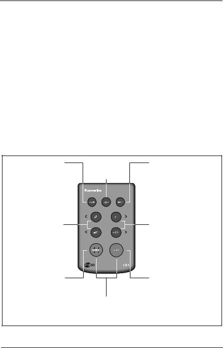
2.2 Using the Pilot Keypad
Keypad functions
The Pilot Keypad enables you to control autopilot operation by means of button presses. Each button press is confirmed by a short beep. Although most functions are controlled by a single button press, there are also some simultaneous two-button operations.
RESP |
DISP |
Press to display current |
Display Pilot |
autopilot response |
Status (page 8-2-4) |
value (page 8-2-6) |
|
Press for 1 second for |
|
rudder gain setting |
|
(page 8-2-24) |
|
Course change keys |
|
Port 1˚ & Port 10˚ |
|
(page 8-2-5) |
|
TRACK
Press for Track mode from Auto (if a navigator is connected)
Press to accept waypoint advance
Press for 1 second to skip waypoint
(page 8-2-13)
Course change keys
Starboard 1˚ & Starboard 10˚
(page 8-2-5)
Press -1 and -10 simultaneously for AutoTack to port
(page 8-2-11)
STANDBY
Press at any time to disable the autopilot and resume manual steering
(page 8-2-5)
STANDBY + AUTO
(simultaneously) Press for Wind Vane mode (if a wind vane is connected)
Press +1 and +10 simultaneously for AutoTack to Starboard
(page 8-2-11)
AUTO
Press for Auto mode
(page 8-2-4)
Press for 1 second for Last Heading (page 8-2-10)
Press again to accept Last Heading
Figure 2-1: Pilot Keypad controls
ST290 Instrument System Owner’s Handbook
8-2-2 |
Section 8: Autopilots |
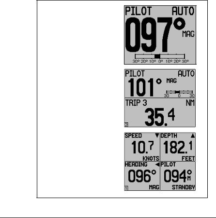
2.3 Display layout
General Operation
Autopilot information is displayed on the ST290 Graphic Display in either single, dualor quad-screen modes.These modes are used for general operation and configuration of the autopilot alongside other features of the ST290. You can configure these screens as part of the Graphic Display User Setup procedure (see Section 7, System Setup).
Note: When your boat is under the control of the autopilot and you wish to access other information on the displays, we recommend that you use the dualor quad-screen mode so that one view can be dedicated to displaying the autopilot status.
.
Example of pilot information on a single-element page. This shows:
•Mode
•Heading
•Heading type: MAG/TRUE
•Rudder bar (-/+ 30°) or XTE bar
Example of pilot information in the upper screen area of a dualelement page. This shows:
•Mode
•Heading
•Heading Type: MAG/TRUE
•Scaled down rudder bar (-/+30°)
Example of pilot information in the lower, right-hand area of a quad-element page. This shows:
•Mode
•Heading
•Heading Type: (M)AG/(T)RUE
1-D6038
Figure 2-2: ST290 display modes
ST290 Instrument System Owner’s Handbook

Chapter 2: Autopilot Operation |
8-2-3 |
|
|
|
|
Pop-up message modes
Alarm and Information messages
Autopilot alarms, information and temporary setting changes are displayed using “ pop-up” style messages. These messages appear in front of the current display (single-, dual or quad-element screen) and indicate a button with an associated action. On taking an action, the display returns to the normal operating mode.
.
Example pop-up alarm message:
This shows an autopilot off course alarm and silence action button, in a pop-up window, over a quad-element page.
1-D6048
Figure 2-3: Pop-up alarm message
Pop-up pilot mode
Autopilot mode or course changes can also be displayed in a “ pop-up” window (see Figure 2-4 ). You can enable or disable this feature as described in the Graphic Display User Setup procedure (see Section 7, System Setup).
.
Example pop-up course-change message:
This example shows a new locked heading, following a commanded course change in AUTO mode.
The pop-up is displayed for 4 seconds.
1-D6050
Figure 2-4: Pop-up pilot mode
ST290 Instrument System Owner’s Handbook

8-2-4 |
Section 8: Autopilots |
2.4 Start-up mode
The autopilot always powers up in Standby mode (manual steering).
2.5 Accessing the Autopilot display page
Autopilot information is displayed on ST290 Graphic Display. You can access the information using either the Graphic Display buttons or the Pilot Keypad buttons.
Using an ST290 Graphic Display:
1.Press the instrument  button to enter Chapter Select mode.
2.Use the  or
or  or
or  button to highlight the PILOT chapter.
3.Either wait for 5 seconds or press the  button to display the PILOT status page.
Using the Pilot Keypad, press the Keypad DISP button once. All ST290 Graphic Displays with PILOT POPUP enabled (see Section 7, User Setup) will immediately show the pilot status on a pop-up page.
2.6 Using Auto mode
WARNING:
Before using Auto mode, make sure that the pilot has been correctly commissioned, as detailed in Section 8, Chapter 4.
Engaging the autopilot (Auto mode)
WARNING:
Autopilots make boating easier, but they are NOT a substitute for good seamanship. ALWAYS maintain a permanent watch at the helm.
To engage the autopilot:
1.Steady the boat on the required heading.
2.Press AUTO. The autopilot will now steer the boat on the current heading (locked heading).
3.The PILOT screen of the ST290 Graphic Display will display the autopilot status and the locked heading. The display in Figure 2-5 shows the autopilot in control of the boat maintaining a locked heading of 097º.
ST290 Instrument System Owner’s Handbook
Chapter 2: Autopilot Operation |
8-2-5 |
||
|
|
|
|
|
|
|
|
D3560-4
Figure 2-5: Engaging the autopilot
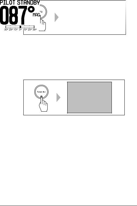
Disengaging the autopilot (Standby mode)
To disengage the autopilot, press STANDBY:
•In Standby mode, the display shows the current compass heading.
•The last locked heading is memorized and can be recalled.
To return to manual steering AT ANY TIME, press STANDBY.
D3561-4
Figure 2-6: Disengaging the autopilot
Changing course in Auto mode
In Auto mode, use the -1 and -10 (port) and +1 and +10 (starboard) buttons to change the locked heading in steps of 1° or 10° . For example: press -10 three times for a 30° course change to port.
ST290 Instrument System Owner’s Handbook
8-2-6 |
Section 8: Autopilots |
Port |
Starboard |
or |
or |
|
D3320-2 |
Figure 2-7: Changing course in AUTO mode
Adjusting autopilot response
You can adjust the performance of Raymarine autopilot systems by changing the response level. This is the only user adjustment you should need to make to the autopilot on a regular basis.
The response level controls the relationship between the autopilot’s course keeping accuracy and the amount of helm/drive activity.
You can set the default power-up response level, by using the Pilot Basic or Advanced Calibration (see Section 8, Chapter 5) to adjust the default response level.
However, when using your autopilot on a day-to-day basis, you can make temporary adjustments to the response level. By doing this you can set the autopilot performance to suit different conditions.
150G & 400G autopilot systems
150G and 400G autopilot systems have nine response level options:
Level 1 gives the least pilot activity to conserve power, but may compromise short-term course-keeping accuracy.
Levels 4 to 6 should give good course keeping with crisp, well-controlled turns under normal operating conditions.
Level 9 gives the tightest course keeping and greatest rudder activity, but may lead to a rough passage in open waters as the autopilot may ‘fight’ the sea.
ST290 Instrument System Owner’s Handbook
Chapter 2: Autopilot Operation |
8-2-7 |
|
|
|
|
When you require extra tight course keeping (e.g. for pilotage in confined and sheltered waters), use a higher response value. If you want to minimize drive activity and conserve battery power, use a lower value.
Temporary changes to response
Taking the above points into account, use the following procedure if you need to make temporary adjustments to the response level of 150G and 400G autopilots, as required:
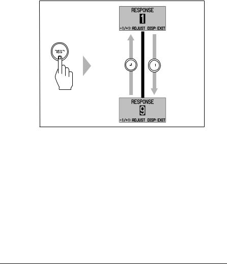
1. Display the RESPONSE screen by pressing the RESP button.
Screen will "pop-up" in front of current view
Decrease
response
1
2
3
4
Increase
5  response
6
7
8
9
D6040-1
Figure 2-8: Making temporary changes to 150G/400G response
2.Press -1 or +1 to change the response level.
3.Press DISP or wait for 10 seconds to return to the previous display.
Note: You will lose these temporary changes to response level whenever the system is powered off. You can make PERMANENT adjustments in Pilot Basic or Advanced Calibration (see Section 8, Chapter 5).
ST290 Instrument System Owner’s Handbook
8-2-8 |
Section 8: Autopilots |
T150 & T400 autopilot systems
T150 and T400 (non-GyroPlus) autopilot systems have three response level options:
Level 1 - AutoSeastate on (Automatic deadband):
•Autopilot gradually ignores repetitive boat movements and only reacts to true variations in course.
•Provides the best compromise between power consumption and course keeping accuracy.
Level 2 - AutoSeastate off (minimum deadband):
•Provides tighter course keeping.
•Increased power consumption and drive unit activity.
Level 3 - AutoSeastate off and counter rudder yaw damping:
•Provides tightest possible course keeping by introducing counter rudder yaw damping (see Section 8, Chapter 5).
Temporary changes to response
To make a temporary change to the response setting of T150 and T400 autopilots:
1.Display the RESPONSE screen by pressing the RESP button.
2.Press -1 or +1 to change the response between levels 1 to 3.
3.Press DISP or wait for 10 seconds to return to the previous display.
Note: You will lose these temporary changes to response level whenever the system is powered off. You can make PERMANENT adjustments in Pilot Basic or Advanced Calibration (see Section 8, Chapter 5).
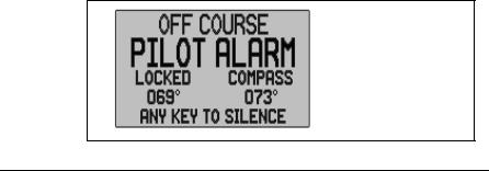
Off Course warning
If an OFF COURSE warning occurs, pop-up window appears displaying the locked and compass bearings.
Message will 'pop-up' in front of current view
D3315-3
Figure 2-9: Off course warning
ST290 Instrument System Owner’s Handbook
Chapter 2: Autopilot Operation |
8-2-9 |
|
|
|
|
The autopilot initiates an OFF COURSE warning when the boat has been off course from the locked heading by more than the specified angle* for longer than 20 seconds.
* Note: You can adjust the specified off course angle in Pilot Advanced Calibration (see Section 8, Chapter 5).
To cancel an OFF COURSE warning, press STANDBY to return to hand steering:
•If you are under sail, check whether your boat is carrying too much sail, or whether the sails are badly balanced. You can usually significantly improve course keeping by improving the sail balance.
•If you are using a powerboat, ensure that the trim tabs are correctly set.
Note: The warning clears automatically if the heading recovers, or if you change the course or if you change the operating mode.
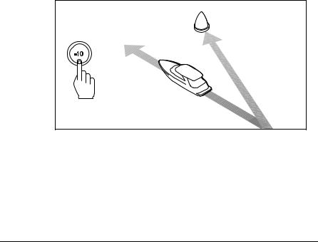
Dodging obstacles then resuming previous course
When your boat is under autopilot control, you can dodge an obstacle and then resume your previous course.
Obstacle
Original
course
Dodge
D3303-2P
Figure 2-10: Dodging an obstacle
Dodging an obstacle
To dodge an obstacle:
1.Select a course change in the appropriate direction. For example, press -10 three times for a 30° dodge to port.
ST290 Instrument System Owner’s Handbook
8-2-10 |
Section 8: Autopilots |
2.When safely clear of the obstacle, you can either:
•Reverse the previous course change (e.g. press +10 three times), or
•Return to the previous locked heading (LAST HEADING) as described below.
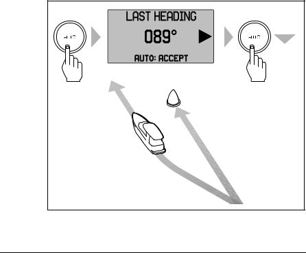
Returning to the previous heading
When the boat is in Auto mode and you have steered the boat away from the selected locked heading for any reason (for example, to carry out a dodge maneuver), you can return to the previous locked heading (the most recent heading held for 20 seconds). To do this:
1.Press AUTO for 1 second. The display flashes and shows the previous locked heading (LAST HEADING) for 10 seconds. The arrow will show the direction the boat will turn.
2.To accept this heading, press AUTO when the display is flashing.
Note: If you do not press AUTO while the display is flashing, the autopilot will maintain the current heading.
1 SECOND |
|
|
Message will "pop-up" infront of current view |
||
Resumed |
Obstacle |
|
course |
||
|
||
|
Original |
|
|
course |
|
|
Dodge |
|
|
D5499-2 |
|
Figure 2-11: Return to last heading
ST290 Instrument System Owner’s Handbook
Chapter 2: Autopilot Operation |
8-2-11 |
|
|
|
|
You can also return to the last Auto heading from Standby mode by pressing AUTO for 1 second and pressing AUTO again at the
LAST HEADING prompt.
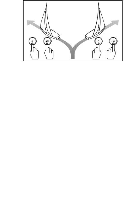
Using sail boat features in Auto mode
Automatic tack (AutoTack)
The ST290 Pilot Keypad has a built in automatic tack facility (AutoTack) that turns the boat through a preset angle in the required direction. The default angle is 100º.
If you have set the vessel type to SAIL BOAT, you can adjust the default AutoTack angle in Pilot Basic or Advanced calibration (see Section 8, Chapter 5):
•To AutoTack to port: press the -1 and -10 buttons together.
•To AutoTack to starboard: press the +1 and +10 buttons together.
WARNING:
When making major course changes, the trim on the boat may change substantially. Because of this, the autopilot may take some time to settle accurately onto the new course.
AutoTack - Port |
AutoTack - Starboard |
Wind |
Wind |
AutoTack |
AutoTack |
angle |
angle |
|
D5399-1 |
Figure 2-12: Using AutoTack
ST290 Instrument System Owner’s Handbook

8-2-12 |
Section 8: Autopilots |
Preventing accidental gybes
Note: For the gybe inhibit feature to work, the autopilot must receive suitable wind information.
A gybe inhibit feature stops AutoTack maneuvers away from the wind thereby preventing accidental gybes. You can turn this feature on or off, as required:
•With gybe inhibit on, you can perform an AutoTack only into the wind.
•With gybe inhibit off, you can perform an AutoTack into or away from the wind.
Note: Gybe inhibit is switched on as a default. You can switch it off in Pilot Basic or Advanced Calibration (see Section 8, Chapter 5).
Gusty conditions
In gusty conditions, the course may tend to wander slightly, particularly if the sails are badly balanced. If you take the appropriate measures, the autopilot will maintain competent control even in gale force conditions.
You can significantly improve course keeping by:
•Improving the sail balance:
•Not allowing the boat to heel over excessively.
•Easing the mainsheet traveller to leeward to reduce heeling and weather helm.
•If necessary, reefing the mainsail a little early.
In very strong winds and large seas:
•Avoid sailing with the wind dead astern.
•Ideally, bring the wind at least 30° away from a dead run.
In severe conditions, you may also need to remove the mainsail and sail under headsail only.
ST290 Instrument System Owner’s Handbook
Chapter 2: Autopilot Operation |
8-2-13 |
|
|
|
|
2.7 Using Track mode
In Track mode, the autopilot maintains a track between waypoints created on a navigation system. The autopilot makes any course changes necessary to keep your boat on track, automatically compensating for tidal streams and leeway.
Selecting Track mode
WARNING:
When you enter Track mode, the autopilot will bring the boat onto the track in a controlled way. The closer the boat is to the correct heading and track, the quicker the autopilot will settle the boat onto the new course. To avoid an unexpected turn, it is good practise to align the boat with the required track before entering Track mode.
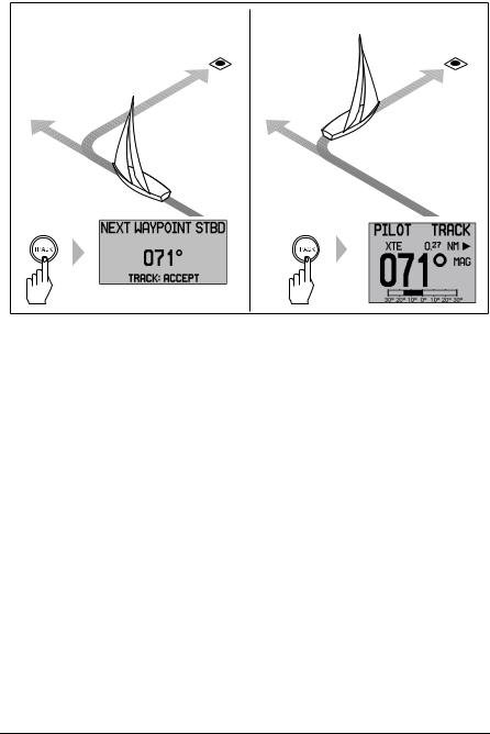
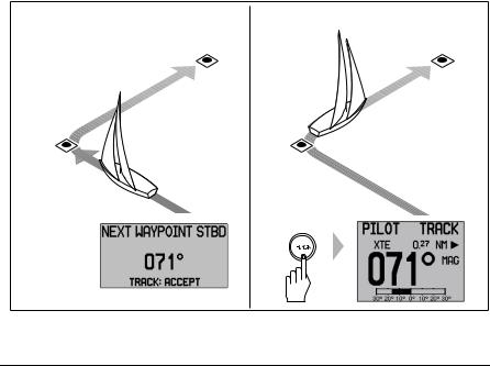
To select Track mode:
1.Ensure the autopilot is in Auto mode.
2.Press TRACK to enter Track mode.
3.Wait for the Waypoint Advance warning to sound. The display will show the bearing to the next planned waypoint and the direction the boat will turn to reach this waypoint.
4.Check that it is safe for the boat to turn onto the new course.
5.Press the TRACK button. When you do this:
•The autopilot will turn the boat onto the new course in a controlled way.
•The display shows the heading required to achieve the required track.
Note: The closer the boat is to the correct heading and track when you press TRACK, the quicker the autopilot will bring the boat onto the new course. If the boat is more than 0.3 nm from the track, the Large Cross Track Error warning will sound.
ST290 Instrument System Owner’s Handbook
8-2-14 |
|
|
|
|
Section 8: Autopilots |
From auto mode, press track to enter Track mode: |
Then press track again to turn boat to waypoint: |
||||
|
|
Waypoint |
|
|
New |
|
|
|
|
||
|
|
at 071˚ |
|
|
Waypoint |
Current |
|
|
Previous |
|
|
|
|||||
heading |
|
|
heading |
|
|
|
|
|
|||
|
|
|
|
|
|
Message will "pop-up" in front of current view
D5414-2
Figure 2-13: Automatic Track Acquisition
Exiting Track mode
To exit Track mode, either:
•Press AUTO to return to Auto mode, or
•Press STANDBY to steer manually in Standby mode.
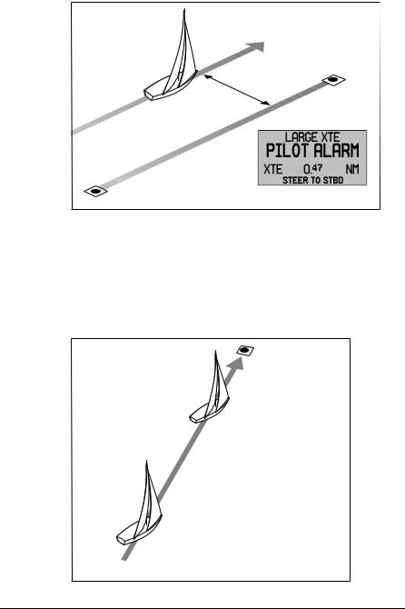
Cross track error
Cross track error (XTE) is the distance between the current position and a planned route. The autopilot receives the cross track error information from the navigation equipment, and uses this to get back on course.
If the cross track error is greater than 0.3 nm, a Large XTE warning will occur. The display will show how far port or starboard of the track you are and the direction you need to steer to get back on track.
ST290 Instrument System Owner’s Handbook
Chapter 2: Autopilot Operation |
8-2-15 |
|
|
|
|
|
Cross track error (XTE) |
|
more than 0.3 nm |
|
Waypoint 2 |
route |
|
Actual |
|
Planned |
route |
|
|
Waypoint 1 |
Message will "pop-up" in front of current view |
D5415-2
Figure 2-14: Large Cross Track Error
Tidal stream compensation
Under most conditions, the autopilot will hold the selected track to within ±0.05 nm (300 ft) or better. The autopilot takes account of the boat’s speed when computing course changes to ensure optimum performance over a wide range of boat speeds.
Boat's speed over ground
Waypoint 2
Tidal |
component |
|
water through speed Boat's
 Waypoint 1
D3261-2
Figure 2-15: Tidal stream compensation
ST290 Instrument System Owner’s Handbook
8-2-16 |
Section 8: Autopilots |
In order of preference, the autopilot uses:
•Measured boat speed (speed through water)
•Speed over ground (SOG), if measured boat speed is not available.
•The cruise speed specified in Pilot Advanced Calibration (see Section 8, Chapter 5), if neither measured boat speed or SOG are available.
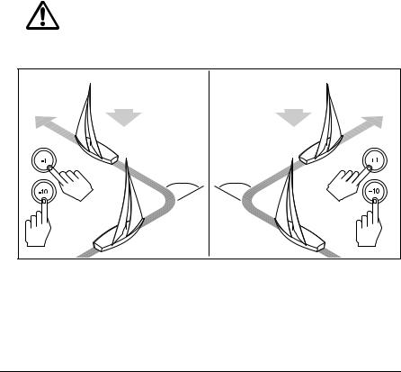
Waypoint arrival and advance
Note: Waypoint advance operates only if valid bearing to waypoint and waypoint name information are available from the navigation system.
On arrival at a waypoint, the autopilot will display the Waypoint Advance (NEXT WAYPOINT) screen and sound an alarm. The alarm screen shows the bearing to the next waypoint and the direction the boat will turn to acquire the new heading.
•If it is safe to make the turn, press the TRACK button to accept the new heading. The autopilot will turn the boat and cancel the alarm.
•If you do not press TRACK then the boat will maintain the existing heading. Pressing AUTO or STANDBY will cancel the alarm, abandon the track and return to automatic or manual mode as appropriate.
Waypoint arrival |
Waypoint advance |
Next target |
New target |
waypoint at 071˚ |
waypoint at 071˚ |
Target |
Old target |
waypoint |
waypoint |
Message will "pop-up" in front of current view
D5416-1
Figure 2-16: Waypoint Arrival and Advance
ST290 Instrument System Owner’s Handbook

Chapter 2: Autopilot Operation |
8-2-17 |
|
|
|
|
Man Overboard (MOB) functionality
On some navigation aids a Man Overboard function exists to aid rescue of personnel. When a MOB button is activated, the position of the boat at that time is stored and sent to the autopilot as a new waypoint. The autopilot can acquire this waypoint via a waypoint advance alarm and automatically track to the MOB location.
Skipping a waypoint – SeaTalk navigators only
WARNING:
Skipping a waypoint will take you straight to the next waypoint. Check your navigation before making the turn.
If you want to advance to the next waypoint before you have arrived at the target waypoint, you can skip a waypoint by pressing TRACK for
1 second. The display will then show the Waypoint Advance screen for the next waypoint. Check it is safe to turn, then press TRACK to turn the boat towards the next waypoint.
Route Complete indication
When you have reached the last waypoint on a route in Track mode, either a NO DATA message or a ROUTE COMPLETE message is displayed.
When this occurs, either:
•Press AUTO to continue on the same heading, or
•Press STANDBY to return to hand steering.
If you do not press a button, the autopilot will continue to steer the boat on the present heading whilst displaying the NO DATA or ROUTE COMPLETE message.
Dodges in Track mode
When the autopilot is in Track mode you still have full control from the keypad.
Initiating a dodge maneuver
In Track mode, you can make a dodge maneuver by using the course change buttons (-1, +1, -10 or +10) to select the desired course change.
ST290 Instrument System Owner’s Handbook

8-2-18 |
Section 8: Autopilots |
Cancelling a dodge maneuver
After you have avoided the hazard, you can cancel the dodge course change by making an equal course change in the opposite direction.
Safety in Track mode
WARNING:
Although Track mode provides accurate track keeping even in complex navigational situations, it is still the skipper’s responsibility to ensure the safety of the boat at all times by means of careful navigation and frequent position checks.
Sailing in Track mode assists precise navigation and removes the tasks of compensating for wind and tidal drift. However, you MUST still maintain an accurate log with regular plots.
Confirming position at the start of a journey
At the start of a journey you must always use an easily identifiable fixed object to confirm the fix given by the navigation system. Check for fixed positional errors and compensate for them.
Verifying computed positions
Always verify the computed position with a dead reckoned position, calculated from the average course steered and the distance logged.
Plot frequency
In open water, you should make plots at least every hour.
In confined waters or when near to potential hazards, you should make plots more frequently.
2.8 Using Wind Vane mode – sail boats
Introduction
Note: To use Wind Vane mode, the autopilot must receive suitable wind information.
When the autopilot is in Wind Vane mode it keeps the boat at a set angle to the wind, using wind and compass references.
ST290 Instrument System Owner’s Handbook
 Loading...