


Section 6: Installation
Contents
Chapter 1: Preparing for Installation ....................................................... |
6-1-1 |
|
1.1 |
Introduction ........................................................................... |
6-1-1 |
1.2 |
Planning the installation ........................................................ |
6-1-6 |
|
EMC Installation Guidelines ................................................. |
6-1-6 |
|
Suppression Ferrites ........................................................ |
6-1-7 |
|
Connections to Other Equipment ..................................... |
6-1-7 |
|
Data Processing Unit ............................................................. |
6-1-7 |
|
USB considerations ......................................................... |
6-1-8 |
|
Transducer Pods ..................................................................... |
6-1-8 |
|
Instruments & keypads .......................................................... |
6-1-9 |
|
Wind, Speed & Depth transducers ........................................ |
6-1-11 |
|
Cable lengths ................................................................... |
6-1-11 |
|
Wind ................................................................................ |
6-1-11 |
|
Speed and Depth ............................................................ |
6-1-12 |
|
Further information ............................................................. |
6-1-14 |
1.3 |
SeaTALK2 requirements ...................................................... |
6-1-14 |
1.4 |
System structures ................................................................. |
6-1-15 |
|
Preliminary information ...................................................... |
6-1-15 |
|
Cables .................................................................................. |
6-1-16 |
|
Power supply ....................................................................... |
6-1-16 |
|
Protection ....................................................................... |
6-1-16 |
1.5 |
Typical systems .................................................................... |
6-1-17 |
Chapter 2: Installation Procedures ........................................................... |
6-2-1 |
|
2.1 |
Introduction ........................................................................... |
6-2-1 |
|
Important ............................................................................... |
6-2-1 |
|
Sequence of operations .......................................................... |
6-2-1 |
2.2 |
Running SeaTalk & SeaTALK2 cables .................................. |
6-2-2 |
|
Cable routing practices .......................................................... |
6-2-2 |
|
Identifying cables .................................................................. |
6-2-2 |
|
Procedure ............................................................................... |
6-2-3 |
|
Pods .................................................................................. |
6-2-4 |
|
System power ................................................................... |
6-2-5 |
2.3 |
Cable preparation ................................................................... |
6-2-5 |
|
General connections .............................................................. |
6-2-5 |
|
Connections to spring retention connectors ........................... |
6-2-6 |
ST290 Instrument System Owner’s Handbook

ii |
|
Section 6: Installation |
2.4 Fitting Data Processing Unit .................................................. |
6-2-7 |
|
|
Connections to DPU .............................................................. |
6-2-8 |
|
SeaTalk & SeaTALK2 ...................................................... |
6-2-8 |
|
Miscellaneous .................................................................. |
6-2-9 |
|
NMEA data .................................................................... |
6-2-10 |
|
Securing cables and replacing cover .................................... |
6-2-11 |
2.5 Fitting Speed, Depth & Wind transducers ........................... |
6-2-11 |
|
|
Speed & Depth ..................................................................... |
6-2-11 |
|
Running transducer cable ............................................... |
6-2-11 |
|
Wind transducer ................................................................... |
6-2-12 |
|
Assembling Wind Vane .................................................. |
6-2-12 |
|
Fitting transducer ........................................................... |
6-2-13 |
|
Running transducer cable ............................................... |
6-2-14 |
2.6 |
Fitting transducer Pods ........................................................ |
6-2-15 |
|
Connecting Pods .................................................................. |
6-2-17 |
|
Identifying connections ................................................. |
6-2-17 |
|
Replacing Pod cover ............................................................ |
6-2-19 |
2.7 Fitting instruments & keypads ............................................. |
6-2-19 |
|
|
General requirements ........................................................... |
6-2-19 |
|
Pilot Keypad .................................................................. |
6-2-19 |
|
Mounting options ................................................................. |
6-2-19 |
|
Instrument & keypad seals ................................................... |
6-2-20 |
|
Procedures ........................................................................... |
6-2-20 |
|
Flush mounting .............................................................. |
6-2-20 |
|
Surface mounting ........................................................... |
6-2-23 |
|
Connecting instruments & keypads ..................................... |
6-2-25 |
|
Made-up cables .............................................................. |
6-2-25 |
|
Unterminated SeaTALK2 cable ..................................... |
6-2-25 |
|
Unused connectors ............................................................... |
6-2-27 |
2.8 |
Making power connections .................................................. |
6-2-27 |
|
Requirements ....................................................................... |
6-2-27 |
|
Power supply capacity ................................................... |
6-2-27 |
|
Grounding the system .................................................... |
6-2-27 |
|
Procedures ........................................................................... |
6-2-29 |
|
Connecting to a system which includes |
|
|
a Raymarine autopilot .................................................... |
6-2-29 |
|
Connecting to a system without |
|
|
a Raymarine autopilot .................................................... |
6-2-29 |
2.9 Preparing ST290 for use ...................................................... |
6-2-30 |
|
|
Initial checks ........................................................................ |
6-2-30 |
|
Setup requirements .............................................................. |
6-2-31 |
|
EMC Conformance .............................................................. |
6-2-31 |
ST290 Instrument System Owner’s Handbook

6-1-1
Chapter 1: Preparing for Installation
1.1 Introduction
This chapter provides information to assist in planning the installation of an ST290 system. As different ST290 systems will comprise different product combinations, the items packed with each product are shown in the following illustrations. A System Pack T22071 containing all the items provided in E22055, E22057, E22067 and E22069, is also available.
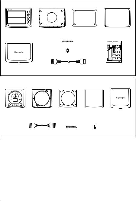
Graphic Instrument Part No. E22057 - pack items
Graphic Instrument |
Digital Instrument |
Digital Instrument |
Digital Instrument |
|
Clamp |
Surface Mount Seal |
Edge Seal |
|
Stud (4 off) |
|
|
|
Thumb-nut (4 off) |
|
|
Digital Instrument |
SeaTALK2 Cable, 400 mm, |
Quick Reference Guide, |
|
Sun Cover |
Plug to Plug |
Part No. 86073-1 |
|
|
|
|
D6020-1 |
s |
Grounding cable, 2 meters |
D6018-2 |
ST290 Instrument System Owner’s Handbook
6-1-2 |
Section 6: Installation |
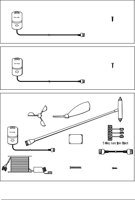
Depth Pod, Part No. E22067 - pack items
Depth Tranducer Pod
No. 6 x 3/4 inch pan-head self-tapping screw (3 off)
SeaTalk Cable Plug, 400 mm
D6021-1
Speed Pod, Part No. E22069 - pack items
Speed Tranducer Pod
No. 6 x 3/4 inch pan-head self-tapping screw (3 off)
SeaTalk Cable Plug, 400 mm
D6022-1
Wind Transducer & Pod, Part No. E22068 - pack items
Anemometer Head
Wind vane head
Wind Transducer Pod
Junction box
SeaTalk Cable Plug, 400 mm 

 Allen key
M5 x 50,
countersunk screws (2 off)
ST60, 50 metre Mount Assembly
Long Arm Mast
Head Transducer
SeaTALK2 Cable, 400 mm, Plug to Plug
No 6 x 3/4 inch pan-head self-tapping screw (3 off)
D6029-2
ST290 Instrument System Owner’s Handbook
Chapter 1: Preparing for Installation |
6-1-3 |
|
|
|
|
Data Instrument Part No. E22056 - pack items
Data Instrument |
Digital Instrument |
Digital Instrument |
Digital Instrument |
|
Clamp |
Surface Mount Seal |
Edge Seal |
|
Stud (4 off) |
|
|
|
Thumb-nut (4 off) |
|
|
Digital Instrument |
SeaTALK2 Cable, 400 mm, |
Quick Reference Guide, |
|
Sun Cover |
Plug to Plug |
Part No. 86073-1 |
|
D6019-1
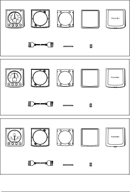
Analog Wind Instrument, Part No. E22059 - pack items
Wind |
Analog |
Analog |
Analog |
Analog |
Analog Instrument |
Instrument Clamp |
Surface Mount |
Edge Seal |
Instrument |
|
|
Seal |
|
Sun Cover |
|
SeaTalk Cable |
Stud (2 off) |
Thumb-nut (2 off) |
|
D6025-1
ST290 Instrument System Owner’s Handbook
6-1-4 |
Section 6: Installation |
Analog Close Hauled Wind Instrument, Part No. E22061 - pack items
Close Hauled Wind |
Analog |
Analog |
Analog |
Analog |
Analog Instrument |
Instrument Clamp |
Surface Mount |
Edge Seal |
Instrument |
|
|
Seal |
|
Sun Cover |
|
SeaTalk Cable |
Stud (2 off) |
Thumb-nut (2 off) |
|
D6026-1
Analog Compass Instrument, Part No. E22060 - pack items
Compass |
Analog |
Analog |
Analog |
Analog |
Analog Instrument |
Instrument Clamp |
Surface Mount |
Edge Seal |
Instrument |
|
|
Seal |
|
Sun Cover |
|
SeaTalk Cable |
Stud (2 off) |
Thumb-nut (2 off) |
|
D6027-1
Analog Rudder Angle Indicator Instrument, Part No. E22062 - pack items
Rudder Angle |
Analog |
Analog |
Analog |
Analog |
Analog Instrument |
Instrument Clamp |
Surface Mount |
Edge Seal |
Instrument |
|
|
Seal |
|
Sun Cover |
|
SeaTalk Cable |
Stud (2 off) |
Thumb-nut (2 off) |
|
D6028-1
ST290 Instrument System Owner’s Handbook
Chapter 1: Preparing for Installation |
6-1-5 |
|
|
|
|
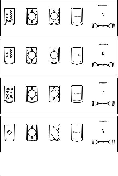
Remote Plus Keypad, Part No. E22065 - pack items
Stud (2 off) |
Thumb-nut (2 off) |
Remote Plus |
Keypad |
Keypad |
Keypad |
|
Keypad |
Clamp |
Seals |
Sun Cover |
SeaTalk Cable |
D6023-1
Remote Keypad, Part No. E22063 - pack items
Stud (2 off) |
Thumb-nut (2 off) |
Remote |
Keypad |
Keypad |
Keypad |
|
Keypad |
Clamp |
Seals |
Sun Cover |
SeaTalk Cable |
D6024-1
Pilot Keypad, Part No. E12094 - pack items
Stud (2 off) |
Thumb-nut (2 off) |
Pilot |
Keypad |
Keypad |
Keypad |
|
Keypad |
Clamp |
Seals |
Sun Cover |
SeaTalk Cable |
D6031-1
MOB Keypad, Part No. E22064 - pack items
Stud (2 off) |
Thumb-nut (2 off) |
MOB |
Keypad |
Keypad |
Keypad |
|
Keypad |
Clamp |
Seals |
Sun Cover |
SeaTalk Cable |
D6030-1
ST290 Instrument System Owner’s Handbook

6-1-6 |
Section 6: Installation |
1.2 Planning the installation
EMC Installation Guidelines
All Raymarine equipment and accessories are designed to the best industry standards for use in the recreational marine environment.
Their design and manufacture conforms to the appropriate Electromagnetic Compatibility (EMC) standards, but correct installation is required to ensure that performance is not compromised. Although every effort has been taken to ensure that they will perform under all conditions, it is important to understand what factors could affect the operation of the product.
The guidelines given here describe the conditions for optimum EMC performance, but it is recognized that it may not be possible to meet all of these conditions in all situations. To ensure the best possible conditions for EMC performance within the constraints imposed by any location, always ensure the maximum separation possible between different items of electrical equipment.
For optimum EMC performance, it is recommended that wherever possible:
•Raymarine equipment and cables connected to it are:
•At least 3 ft (1 m) from any equipment transmitting or cables carrying radio signals e.g. VHF radios, cables and antennas. In the case of SSB radios, the distance should be increased to 7 ft (2 m).
•More than 7 ft (2 m) from the path of a radar beam. A radar beam can normally be assumed to spread 20 degrees above and below the radiating element.
•The equipment is supplied from a separate battery from that used for engine start. Voltage drops below 10 V, and starter motor transients, can cause the equipment to reset. This will not damage the equipment, but may cause the loss of some information and may change the operating mode.
•Raymarine specified cables are used. Cutting and rejoining these cables can compromise EMC performance and must be avoided unless doing so is detailed in the installation manual.
•If a suppression ferrite is attached to a cable, this ferrite should not be removed. If the ferrite needs to be removed during installation it must be reassembled in the same position.
ST290 Instrument System Owner’s Handbook
Chapter 1: Preparing for Installation |
6-1-7 |
|
|
|
|
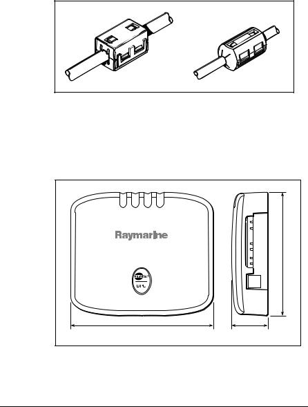
Suppression Ferrites
The following illustration shows typical cable suppression ferrites used with Raymarine equipment. Always use the ferrites supplied by Raymarine.
D3548-2 |
Connections to Other Equipment
If your Raymarine equipment is to be connected to other equipment using a cable not supplied by Raymarine, a suppression ferrite MUST always be attached to the cable near to the Raymarine unit.
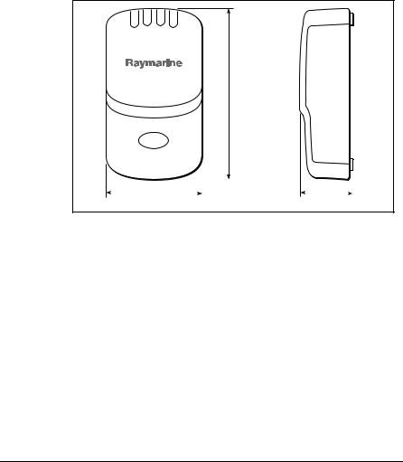
Data Processing Unit
|
5.12 in (130 mm) |
5.9 in (150 mm) |
1.53 in |
|
(39 mm) |
|
D5536-1 |
Figure 1-1: DPU dimensions
ST290 Instrument System Owner’s Handbook
6-1-8 |
Section 6: Installation |
CAUTION:
The DPU is not waterproof and so must be installed in a dry location.
The DPU must be positioned below decks in a dry location where:
•It is protected against physical damage.
•It is at least 9 in (230 mm) from a compass.
•It is at least 20 in (500 mm) from radio receiving equipment.
•There is reasonable access for installation and servicing.
Transducer Pods
4.61 in (117 mm)
|
|
|
|
|
|
|
|
|
|
|
|
|
|
|
|
|
|
|
|
|
|
|
|
|
|
|
|
|
|
|
|
|
|
|
|
|
|
|
|
2.6 in (66 mm) |
|
1.42 in (36 mm) |
|||||
D5537-1
Figure 1-2: Transducer Pod dimensions
CAUTION:
The transducer Pods are not waterproof and so must be installed in a dry location.
Each transducer Pod must be positioned below decks in a dry location where:
•It is protected against physical damage.
•It is at least 9 in (230 mm) from a compass.
•It is at least 20 in (500 mm) from radio receiving equipment.
•There is reasonable access for installation and servicing.
ST290 Instrument System Owner’s Handbook
Chapter 1: Preparing for Installation |
6-1-9 |
|
|
|
|
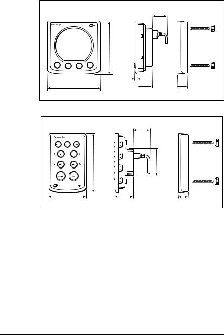
Instruments & keypads
Templates to facilitate instrument and keypad installation are provided in Section 11 of this handbook.
The necessary mounting surface thickness for the different instrument and keypad types, are summarized in Table 1-1 .
Table 1-1: Mounting surface thickness
|
|
Mounting surface |
||
Product |
Minimum thickness |
Maximum thickness |
||
|
|
|
|
|
Digital instruments |
1/8 |
inch (3 mm) |
1 inch (25 mm) |
|
|
|
|
|
|
Analog instruments |
1/8 |
inch (3 mm) |
3/4 |
inch (20 mm) |
|
|
|
|
|
Keypads |
1/8 |
inch (3 mm) |
3/4 |
inch (20 mm) |
|
|
|
|
|
The maximum thicknesses given in Table 1-1 apply when using the standard fixing studs supplied with your ST290 product. If you want to install an ST290 product in a mounting surface thicker than the maximum quoted thickness, use an M4 stud x 0.7 mm pitch, of the appropriate length.
|
|
1.38 in (35 mm) |
|
|
|
minimum clearance |
|
|
(124 mm ) |
|
|
|
4.9 in |
|
|
6.7 in (170 mm) |
0.3 in |
1.6 in |
1.0 in |
|
(7.65 mm) |
||
|
|
(39.5 mm) |
(25.1 mm) |
|
|
|
D5534-1 |
Figure 1-3: Digital instrument dimensions
ST290 Instrument System Owner’s Handbook
6-1-10 |
Section 6: Installation |
1.38 in (35 mm) minimum clearance
|
4.9 in (124 mm) |
|
|
0.3 in |
|
|
(7.65 mm) |
|
4.9 in (124 mm) |
1.33 in |
1.0 in |
|
(33.75 mm) |
(25.1 mm) |
|
|
D5535-1 |
Figure 1-4: Analog instrument dimensions
|
1.38 in (35 mm) |
|
|
minimum clearance |
|
|
4.88 in (124 mm) |
2.2 in (56.5 mm) diameter |
3.1 in (78.5 mm) |
1.61 in (41 mm) |
0.8 in (20 mm) |
D5539-1
Figure 1-5: Keypad dimensions
CAUTION:
The presence of moisture at the rear of an instrument or keypad could cause damage either by entering the instrument through the breathing hole or by coming into contact with the electrical connectors.
Each ST290 instrument and keypad can be fitted either above or below deck, provided:
•The rear of each product is protected from water.
•Instruments are easily read by the helmsman.
•Keypads are easily operable.
•Each product is protected against physical damage.
•Each product is at least 9 in (230 mm) from a compass.
ST290 Instrument System Owner’s Handbook
Chapter 1: Preparing for Installation |
6-1-11 |
|
|
|
|
•Each product is at least 20 in (500 mm) from radio receiving equipment.
•There is reasonable rear access for installation and servicing.
Wind, Speed & Depth transducers
Cable lengths
The Wind, Speed and Depth transducer types connect to SeaTALK2 via an associated Pod. The transducers are supplied with fitted cables, as follows:
•Wind: 164 ft (50 m)
•Depth/Speed: 45 ft (13.7 m)
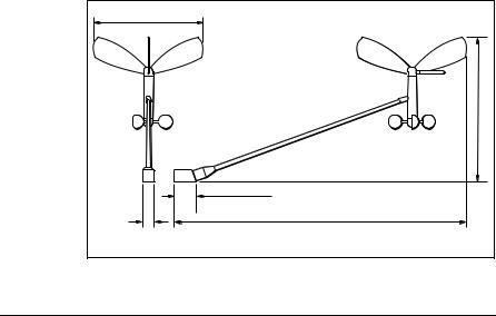
Wind
The Wind transducer is supplied with a junction box and a set of spade terminals. The intended location for the wind transducer must:
•Be as high as possible and away from any equipment which may shield the transducer or otherwise disturb the air flow.
•Allow reasonable access for installation and servicing.
•Provide a horizontal mounting surface. If a surface (e.g. mast top) is otherwise suitable but not horizontal, make up a suitable wedged packing piece to provide the necessary horizontal surface.
12.2in (310 mm)
15.2 in (386 mm)
|
2.5 in (63.5 mm) |
1.25 in |
33.5 in (850 mm) |
(31.75 mm)
D5602-1
Figure 1-6: Wind Transducer dimensions
ST290 Instrument System Owner’s Handbook
6-1-12 |
Section 6: Installation |
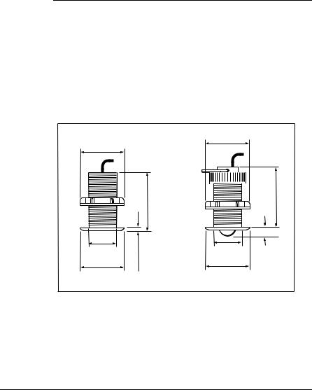
Speed and Depth
A wide range of through-hull Speed and Depth transducers are available, suitable for GRP, steel and aluminum hulled vessels (see Table 1-2 ). Please consult your Raymarine dealer for advice on the most appropriate transducer type for your vessel.
Table 1-2: Summary of transducer types
Hull material |
Speed transducer |
Depth transducer |
|
|
|
GRP |
M78712 Through hull plastic |
M78713 Through hull plastic or |
|
|
M78718 Retractable through hull. |
|
|
|
Steel |
M78712 Through hull plastic |
M78713 Through hull plastic or |
|
|
M78718 Retractable through hull. |
|
|
|
Aluminium |
M78712 Through hull plastic |
M78713 Through hull plastic or |
|
|
M78718 Retractable through hull. |
|
|
|
Wood |
M78716 Through hull bronze |
M78714 Through hull bronze |
|
|
|
2.94 in. (75 mm)
diameter |
|
|
in. (89 mm) |
Depth |
3.50 |
|
|
2.0 in. (51 mm) |
|
diameter |
|
2.94 in. (75 mm) |
0.19 in. |
diameter |
(5 mm) |
2.94 in. (75 mm) diameter
Speed |
3.95 in. (100 mm) |
|
|
2.0 in. (51 mm) |
0.57 in. |
diameter |
(14 mm) |
2.94 in. (75 mm) diameter
D5662-1
Figure 1-7: Typical plastic through hull transducer dimensions
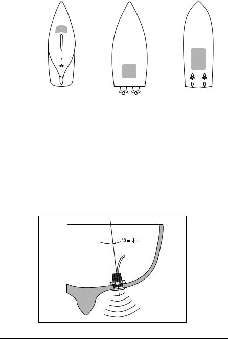
Siting
Speed and Depth transducers should be sited within the clear water flow areas indicated by the shaded areas in Figure 1-8 .
ST290 Instrument System Owner’s Handbook
Chapter 1: Preparing for Installation |
6-1-13 |
|
|
|
|
|
|
|
|
|
|
|
Sailing vessel |
Planing power vessel |
Displacement power vessel |
||||
|
|
|
|
|
|
D5514-1 |
Figure 1-8: Speed & Depth Transducer siting
Each transducer should also:
•Be ahead of the propellers by at least 10% of the water line length.
•Be at least 6 in (150 mm) away from the keel (ideally ahead of the keel if a sailing yacht).
•Be as near as possible to the centre line of the vessel.
•Be clear of other through-hull fittings or projections.
•Have sufficient clearance inside the hull to enable the nut to be fitted.
•Have 4 in (100 mm) of space above it, to allow for withdrawal.
In addition to the above requirements, the depth transducer must be mounted within 10° of the vertical, forward, aft and athwart ships.
D4350-4
Figure 1-9: Depth Transducer maximum angle ST290 Instrument System Owner’s Handbook
6-1-14 |
Section 6: Installation |
Further information
For advice or further information regarding the installation of any ST290 product, please contact the Raymarine Product Support Department or your local Raymarine dealer. Technical Support information in given in Section 5 of this handbook.
1.3 SeaTALK2 requirements
Each SeaTALK2 product is labelled with a Load Equivalency Number (LEN), to indicate how much power it consumes (see Table 1-3 ).
Table 1-3: Load Equivalence Numbers
Product |
LEN |
|
|
Digital instrument |
6 |
|
|
DPU |
5 |
|
|
Transducer Pods |
1 |
|
|
In order to achieve optimum performance, always observe the following guidelines when installing SeaTALK2 cables:
•A terminator plug is required AT EACH END of the main SeaTALK2 cable run (see Figure 1-10 ).
|
|
Terminator in |
|
B |
SPUR |
empty socket |
|
C |
|||
|
A
Data
Processing
Unit
D |
E |
Terminator |
|
|
|
5-way |
|
5-way |
connector |
RF ground |
connector |
block |
|
block |
|
|
D5545-2 |
Figure 1-10: SeaTALK2 dimensions
ST290 Instrument System Owner’s Handbook

Chapter 1: Preparing for Installation |
6-1-15 |
|
|
|
|
•The total length of the SeaTALK2 main cable run must be no more than 655 ft (200 m). The main cable run is defined as the total length of cable between the two terminators. For example, in Figure 1-10 , the length of the main cable run is the sum of distances A+B+C+D+E.
•Where it is impractical to connect a product in a daisy-chained manner, a connector block and spur cable can be used. Where this method is used, the length of the spur cable must not exceed 3 ft (1 m).
•The sum of the LENs of all individual products in a SeaTALK2 system must not exceed 100. If this value exceeds 100 in the system you are planning, contact the Raymarine Technical Support Department or your local Raymarine Dealer for advice.
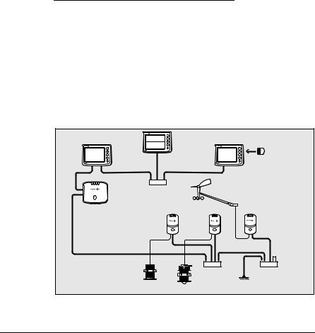
1.4System structures
Preliminary information
Before running cables, refer to Table 1-4 , to determine which bus type (SeaTalk or SeaTALK2) is required for each product you intend installing. A summary of the various ST290 components and their associated bus connections is shown in Table 1-4 .
Table 1-4: Bus allocations
Component |
Bus connections |
|
|
DPU |
SeaTALK2 and SeaTalk. NMEA 2000, NMEA 0183 |
|
and USB ports are also available. |
|
|
Digital instruments (Graphic & Data) |
SeaTALK2 |
|
|
Transducer Pods (all types) |
SeaTALK2 |
Analog instruments (all types) |
SeaTalk |
|
|
Keypads (all types) |
SeaTalk |
|
|
Spend some time determining the best positions for the instruments and transducers, such that the conditions described under Planning the installation are satisfied. If you are planning to utilize the NMEA0183, NMEA2000 or USB interfaces, for other products (e.g. GPS), you must also take this into account when positioning your ST290 products.
In an ST290 system the Data Processing Unit (DPU) controls the operation of the system, and connects to the other system components via SeaTalk and SeaTALK2 buses. The Digital instruments and the
ST290 Instrument System Owner’s Handbook
 Loading...