


RLX-IFHE
RadioLinx Industrial Wireless
RadioLinx® Industrial Frequency
Hopping Ethernet Radios
November 19, 2013
USER MANUAL
Your Feedback Please
We always want you to feel that you made the right decision to use our products. If you have suggestions, comments, compliments or complaints about our products, documentation, or support, please write or call us.
How to Contact Us
ProSoft Technology
5201 Truxtun Ave., 3rd Floor Bakersfield, CA 93309
+1 (661) 716-5100
+1 (661) 716-5101 (Fax) www.prosoft-technology.com support@prosoft-technology.com
Copyright © 2013 ProSoft Technology, Inc., all rights reserved.
RLX-IFHE User Manual
November 19, 2013
ProSoft Technology ®, ProLinx ®, inRAx ®, ProTalk ®, and RadioLinx ® are Registered Trademarks of ProSoft Technology, Inc. All other brand or product names are or may be trademarks of, and are used to identify products and services of, their respective owners.
ProSoft Technology® Product Documentation
In an effort to conserve paper, ProSoft Technology no longer includes printed manuals with our product shipments. User Manuals, Datasheets, Sample Ladder Files, and Configuration Files are provided on the enclosed CD-ROM in Adobe® Acrobat Reader file format (.PDFs). These product documentation files may also be freely downloaded from our web site: www.prosoft-technology.com
Important Safety Information
The following Information and warnings pertaining to the radio module must be heeded.
WARNING – EXPLOSION HAZARD – DO NOT REPLACE ANTENNAS UNLESS POWER HAS BEEN SWITCHED OFF OR THE AREA IS KNOWN TO BE NON-HAZARDOUS.
"THIS DEVICE CONTAINS A TRANSMITTER MODULE, FCC ID: . PLEASE SEE FCC ID LABEL ON BACK OF DEVICE."
"THIS DEVICE USES AN INTERNAL COMPACT FLASH RADIO MODULE AS THE PRIMARY RADIO COMPONENT. THE COMPACT FLASH RADIO MODULE DOES NOT HAVE AN FCC ID LABEL. THE COMPACT FLASH RADIO MODULE HAS NO USER SERVICEABLE PARTS."
"THIS DEVICE COMPLIES WITH PART 15 OF THE FCC RULES. OPERATION IS SUBJECT TO THE FOLLOWING TWO CONDITIONS: (1) THIS DEVICE MAY NOT CAUSE HARMFUL INTERFERENCE, AND (2) THIS DEVICE MUST ACCEPT ANY INTERFERENCE RECEIVED, INCLUDING INTERFERENCE THAT MAY CAUSE UNDESIRED OPERATION."
"CHANGES OR MODIFICATIONS NOT EXPRESSLY APPROVED BY THE PARTY RESPONSIBLE FOR
COMPLIANCE COULD VOID THE USER’s AUTHORITY TO OPERATE THE EQUIPMENT."
Industry Canada Requirements
"THIS DEVICE HAS BEEN DESIGNED TO OPERATE WITH AN ANTENNA HAVING A MAXIMUM GAIN OF 24 dB. AN ANTENNA HAVING A HIGHER GAIN IS STRICTLY PROHIBITED PER REGULATIONS OF INDUSTRY CANADA. THE REQUIRED ANTENNA IMPEDANCE IS 50 OHMS."
"TO REDUCE POTENTIAL RADIO INTERFERENCE TO OTHER USERS, THE ANTENNA TYPE AND ITS GAIN SHOULD BE CHOSEN SUCH THAT THE EQUIVALENT ISOTROPICALLY RADIATED POWER (EIRP) IS NOT MORE THAN THAT REQUIRED FOR SUCCESSFUL COMMUNICATION."
"THE INSTALLER OF THIS RADIO EQUIPMENT MUST INSURE THAT THE ANTENNA IS LOCATED OR POINTED SUCH THAT IT DOES NOT EMIT RF FIELD IN EXCESS OF HEALTH CANADA LIMITS FOR THE GENERAL POPULATION; CONSULT SAFETY CODE 6, OBTAINABLE FROM HEALTH CANADA."
RLX-IFHxE Recommended Antennas
Recommended Antennas
Part Number |
Max Gain |
Part Number |
Max Gain |
Part Number |
Max Gain |
A902S-OA |
2 dBi |
A2424NJ-DB |
24 dBi |
A2410NJ-DY |
10 dBi |
A907NJ-OC |
7 dBi |
A082503-80-OBH |
3 dBi |
A2415NJ-DY |
15 dBi |
A908NJ-DY |
8 dBi |
A911NJ-DY |
11 dBi |
A2402S-OS |
2 dBi |
A2402S-OSLP |
2 dBi |
A2403NBH-OC |
3 dBi |
A2404NBHW-OC |
4 dBi |
A2404NJ-OC |
4 dBi |
A2405S-OA |
5 dBi |
A2405S-OM |
5 dBi |
A2505S-OS |
5 dBi |
A2406NJ-OC |
6 dBi |
A2406NJ-OCD |
6 dBi |
A2408NJ-OC |
8 dBi |
A2409NJ-OCD |
9 dBi |
A2415NJ-OC |
15 dBi |
A902NJ-OC |
2 dBi |
A902S-OA |
2 dBi |
A903NBH-OC |
3 dBi |
A903S-OM |
3 dBi |
A905NJ-OC |
5 dBi |
A907NJ-OC |
7 dBi |
A2408NJ-DP |
8 dBi |
A2413NJ-DP |
13 dBi |
A2416NJ-DP |
16 dBi |
A2419NJ-DP |
19 dBi |
A912NJ-DP |
12 dBi |
A2419NJ-DB |
19 dBi |

Antenna spacing requirements for user safety
It is important to keep the radio's antenna a safe distance from the user. To meet the requirements of FCC part 2.1091 for radio frequency radiation exposure, this radio must be used in such a way as to guarantee at least 20 cm between the antenna and users. Greater distances are required for high-gain antennas. The FCC requires a minimum distance of 1 mW *cm2 power density from the user (or 20 cm, whichever is greater).
If a specific application requires proximity of less than 20 cm, the application must be approved through the FCC for compliance to part 2.1093.
Important Installation Instructions
This equipment is suitable for use in Class I, Division 2, Groups A, B, C and D OR non-hazardous locations only.
WARNING – EXPLOSION HAZARD – DO NOT DISCONNECT EQUIPMENT UNLESS POWER HAS BEEN REMOVED OR THE AREA IS KNOWN TO BE NON-HAZARDOUS.
WARNING – EXPLOSION HAZARD - SUBSTITUTION OF ANY COMPONENTS MAY IMPAIR SUITABILITY FOR CLASS I, DIVISION 2.
Power must be provided from NEC Class 2 Circuit or a Limited Power Source.
EU Requirements
1.For outdoor use, France has a frequency restriction of 2.4 GHz to 2.454 GHz for an output power greater than 10 mW and below 100 mW.
2.For outdoor use in France, the output power is restricted to 10 mW in the frequency range of 2.454 GHz to 2.4835 GHz.
3.5.15 GHz to 5.35 GHz is restricted to 200 mW EIRP throughout the European Union.
RadioLinx IFH: FCC Part 15 & Industry Canada Rules
The statements contained in this "Regulatory Approvals" section are required. If the ProSoft Technology, RadioLinx wireless modem and switches are used as a component of any device, these statements must be a component of that device’s product documentation.
RadioLinx IFHE: COMPLIANCE STATEMENT
The ProSoft Technology, RadioLinx devices comply with Part 15 of the FCC Rules as well as Industry Canada Rules. Operation is subject to the following two conditions:
This device may not cause harmful interference, and,
This device must accept any interference received, including interference that may cause undesired operation.
In Canada, this device is to be operated indoors only and away from windows to provide maximum shielding and to prevent radio interference to the Canadian licensed service. Equipment (or its transmit antenna) that is installed outdoors in Canada is subject to licensing.
Note: The ProSoft Technology, RadioLinx module is labeled with an FCC ID number and a Canadian Certification Number. If this label is not visible when installed in an end-device, the outside of the device MUST also display a label referring to the enclosed RadioLinx. Use wording on the label similar to the following:
RLX-IFH9E: "Transmitter Module FCC ID: NS906P21, Canada 3143AO6P21"
RLX-IFH24E: "Transmitter Module FCC ID: IC NS907P23, Canada 3143AO7P23"
OR
RLX-IFH9E: "This device contains Transmitter Module FCC ID: NS906P21, Canada 3143AO6P21" RLX-IFH24E: "This device contains Transmitter Module FCC ID: NS907P23, Canada 3143AO7P23" WARNING: Changes or modifications to this radio module not expressly approved by its manufacturer, ProSoft Technology, may void the user’s authority to operate the equipment.

Agency Approvals & Certifications
Wireless Approvals
Visit our web site at www.prosoft-technology.com for current wireless approval information.
Hazardous Locations
ANSI/ISA
CSA
ATEX
UL/cUL; Class 1, Div 2
Ordinary Locations
CSA/CB
FCC/IC
ETSI
Agency Approvals & Certifications
Wireless Approvals
Visit our website at www.prosoft-technology.com for current wireless approval information.
RLX-IFHE ♦ RadioLinx Industrial Wireless |
Contents |
RadioLinx® Industrial Frequency Hopping Ethernet Radios |
User Manual |
|
|
Contents
|
|
Your Feedback Please........................................................................................................................ |
2 |
||
|
|
How to Contact Us .............................................................................................................................. |
2 |
||
|
|
ProSoft Technology® Product Documentation .................................................................................... |
2 |
||
|
|
Important Safety Information............................................................................................................... |
3 |
||
|
|
RLX-IFHxE Recommended Antennas ............................................................................................... |
3 |
||
|
|
Recommended Antennas ................................................................................................................... |
3 |
||
|
|
Antenna spacing requirements for user safety ................................................................................... |
4 |
||
|
|
Important Installation Instructions ....................................................................................................... |
4 |
||
|
|
EU Requirements................................................................................................................................ |
4 |
||
|
|
RadioLinx IFH: FCC Part 15 & Industry Canada Rules ...................................................................... |
4 |
||
|
|
RadioLinx IFHE: COMPLIANCE STATEMENT .................................................................................. |
4 |
||
|
|
Agency Approvals & Certifications...................................................................................................... |
5 |
||
|
|
Agency Approvals & Certifications...................................................................................................... |
5 |
||
|
Guide to the RLX-IFHE User Manual |
11 |
|||
|
|
|
|
|
|
1 |
Start Here |
|
13 |
||
|
|
|
|
|
|
|
|
1.1 |
About the RadioLinx Industrial Frequency Hopping Radios ................................... |
13 |
|
|
|
1.1.1 |
Product Specifications - RLX-IFH9E ....................................................................... |
13 |
|
|
|
1.1.2 |
Product Specifications - RLX-IFH24E ..................................................................... |
15 |
|
|
|
1.2 |
Package Contents ................................................................................................... |
16 |
|
|
|
1.3 |
System Requirements ............................................................................................. |
17 |
|
|
|
1.4 |
Installing ControlScape FH Configuration Software................................................ |
18 |
|
|
|
1.5 |
Planning the Network .............................................................................................. |
19 |
|
|
|
1.5.1 |
Installation Questions .............................................................................................. |
20 |
|
|
|
1.5.2 |
ProSoft Wireless Designer ...................................................................................... |
21 |
|
|
|
1.6 |
Configuring the Radios............................................................................................ |
23 |
|
|
|
1.6.1 |
Start ControlScape FH ............................................................................................ |
23 |
|
|
|
1.6.2 |
Set Up the Network ................................................................................................. |
24 |
|
|
|
1.6.3 |
General Radio Configuration................................................................................... |
34 |
|
|
|
1.6.4 |
Set Up the Master Radio ......................................................................................... |
35 |
|
|
|
1.6.5 |
Adding Remote Radios ........................................................................................... |
40 |
|
|
|
1.6.6 |
Add Repeaters ........................................................................................................ |
41 |
|
|
|
1.6.7 |
Graphically Defining the RF Link............................................................................. |
43 |
|
|
|
1.6.8 |
Saving the Network Configuration........................................................................... |
45 |
|
|
|
1.6.9 |
Transfer the Configuration to the Remote Radios .................................................. |
46 |
|
|
|
1.7 |
Planning the Physical Installation............................................................................ |
48 |
|
|
|
1.8 |
Testing the Network Installation Plan ...................................................................... |
49 |
|
|
|
1.9 |
Verifying Communication ........................................................................................ |
50 |
|
|
|
1.9.1 |
Viewing Operating Network..................................................................................... |
50 |
|
|
|
1.9.2 |
Viewing Signal Strength .......................................................................................... |
51 |
|
|
|
1.9.3 |
Getting Radio Status ............................................................................................... |
52 |
|
|
2 |
Installing the Radios |
55 |
||
|
|
|
|
|
|
|
|
2.1 |
Radio Hardware ...................................................................................................... |
56 |
|
|
|
2.1.1 |
Radio power requirements ...................................................................................... |
56 |
|
|
|
2.1.2 |
Connecting antennas .............................................................................................. |
56 |
|
|
|
|
|
|
|
ProSoft Technology, Inc. |
|
Page 7 of 109 |
|||
November 19, 2013 |
|
|
|
||
Contents |
|
|
RLX - IFHE ♦ RadioLinx Industrial Wireless |
|||
User Manual |
RadioLinx® Industrial Frequency Hopping Ethernet Radios |
|||||
|
|
|
|
|
|
|
|
|
2.2 |
Connecting the Radio to a Network Device |
............................................................ |
58 |
|
|
|
2.2.1 |
Cable Connections ................................................................................................. |
|
58 |
|
3 |
Diagnostics and Troubleshooting |
|
67 |
|||
|
|
|
|
|
|
|
|
|
3.1 |
Diagnostics Overview ............................................................................................. |
|
68 |
|
|
|
3.2 |
LED Status Indicators ............................................................................................. |
|
69 |
|
|
|
3.3 |
Sources of Interference .......................................................................................... |
|
70 |
|
|
|
3.3.1 |
Changing a Network's Channel .............................................................................. |
|
70 |
|
|
|
3.3.2 |
Viewing Radio Channel Noise Level ...................................................................... |
|
71 |
|
|
|
3.3.3 |
IFHE Spectrum Analyzer Dialog Box...................................................................... |
|
73 |
|
|
|
3.4 |
Troubleshooting ControlScape FH Error Messages............................................... |
74 |
||
|
|
3.4.1 |
Radio Configuration Status Dialog Box .................................................................. |
|
74 |
|
|
|
3.4.2 |
Invalid Password Dialog Box .................................................................................. |
|
74 |
|
|
|
3.4.3 |
Check the Ethernet cable ....................................................................................... |
|
74 |
|
|
|
3.4.4 |
Connection Errors ................................................................................................... |
|
75 |
|
|
|
3.5 |
Troubleshooting Missing Radios............................................................................. |
|
76 |
|
|
|
3.6 |
RadioLinx OPC Server ........................................................................................... |
|
77 |
|
|
|
3.6.1 |
System Requirements ............................................................................................ |
|
77 |
|
4 |
Reference |
|
|
79 |
||
|
|
|
|
|
|
|
|
|
4.1 |
Antennas................................................................................................................. |
|
80 |
|
|
|
4.1.1 |
Antenna location, spacing, and mounting............................................................... |
|
80 |
|
|
|
4.1.2 |
Antenna Pattern ...................................................................................................... |
|
81 |
|
|
|
4.1.3 |
Antenna Gain .......................................................................................................... |
|
81 |
|
|
|
4.1.4 |
Antenna Polarity ..................................................................................................... |
|
82 |
|
|
|
4.1.5 |
Whip antennas ........................................................................................................ |
|
82 |
|
|
|
4.1.6 |
Collinear array antennas......................................................................................... |
|
83 |
|
|
|
4.1.7 |
Yagi Array Antenna................................................................................................. |
|
84 |
|
|
|
4.1.8 |
Parabolic reflector antennas ................................................................................... |
|
85 |
|
|
Glossary of Terms |
|
86 |
|||
|
|
|
|
|
|
|
5 |
Support, Service & Warranty |
|
99 |
|||
|
|
|
|
|
|
|
|
|
Contacting Technical Support .......................................................................................................... |
|
99 |
||
|
|
5.1 |
Return Material Authorization (RMA) Policies .............................and Conditions |
101 |
||
|
|
5.1.1 |
Returning Any Product.......................................................................................... |
|
101 |
|
|
|
5.1.2 |
Returning Units Under Warranty........................................................................... |
|
102 |
|
|
|
5.1.3 |
Returning Units Out of Warranty........................................................................... |
|
102 |
|
|
|
5.2 |
LIMITED WARRANTY .......................................................................................... |
|
103 |
|
|
|
5.2.1 |
What Is Covered By This Warranty ...................................................................... |
|
103 |
|
|
|
5.2.2 |
What Is Not Covered By This Warranty................................................................ |
|
104 |
|
|
|
5.2.3 |
Disclaimer Regarding High Risk Activities............................................................ |
|
104 |
|
|
|
5.2.4 |
Intellectual Property Indemnity ............................................................................. |
|
105 |
|
|
|
5.2.5 |
Disclaimer of all Other Warranties ........................................................................ |
|
105 |
|
|
|
5.2.6 |
Limitation of Remedies ** ..................................................................................... |
|
106 |
|
|
|
5.2.7 |
Time Limit for Bringing Suit................................................................................... |
|
106 |
|
|
|
5.2.8 |
No Other Warranties ............................................................................................. |
|
106 |
|
|
|
5.2.9 |
Allocation of Risks ................................................................................................ |
|
106 |
|
|
|
5.2.10 |
Controlling Law and Severability .......................................................................... |
|
106 |
|
|
|
|
|
|
||
Page 8 of 109 |
|
ProSoft Technology, Inc. |
||||
|
|
|
|
|
November 19, 2013 |
|

RLX-IFHE ♦ RadioLinx Industrial Wireless |
Contents |
||
RadioLinx® Industrial Frequency Hopping Ethernet Radios |
User Manual |
||
|
|
|
|
|
Index |
107 |
|
|
|
|
|
ProSoft Technology, Inc. |
Page 9 of 109 |
November 19, 2013 |
|

Contents |
RLX-IFHE ♦ RadioLinx Industrial Wireless |
User Manual |
RadioLinx® Industrial Frequency Hopping Ethernet Radios |
|
|
Page 10 of 109 |
ProSoft Technology, Inc. |
|
November 19, 2013 |
RLX-IFHE ♦ RadioLinx Industrial Wireless |
Guide to the RLX-IFHE User Manual |
RadioLinx® Industrial Frequency Hopping Ethernet Radios |
User Manual |
|
|
Guide to the RLX-IFHE User Manual
Function
Introduction
(Must Do)
Configuring the Radios
Installing the Radios
Diagnostic and
Troubleshooting
Reference
Physical Installation
Antenna Selection
Glossary
Support, Service, and
Warranty
Index
Section to Read |
Details |
|
|
Start Here (page 12) |
This section introduces the customer to the |
|
module. Included are: package contents, |
|
system requirements, hardware installation, and |
|
basic configuration. |
|
|
Set Up the Network (page 24)
Set Up the Master Radio (page 35)
Add Remote Radios and Repeaters (page 40)
Save the Radio Configuration (page 39)
This section describes the procedure for designing and configuring a network of RLXIFHE radios.
Radio Hardware (page 56)
Connecting antennas (page 56)
Connecting Radios to a Device Network (page 58)
This section describes how to install the radio hardware, connect antennas, and connect the radios to networked devices.
Verify |
This section describes how to verify |
Communication |
communications with the network. Diagnostic |
(page 50) |
and Troubleshooting procedures. |
Diagnostics and |
|
Troubleshooting |
|
(page 67, page 68) |
|
|
|
Reference (page 79) |
These sections contain general references |
Product |
associated with this product, Specifications, and |
Specifications (page |
the Functional Overview. |
|
|
13) |
|
|
|
|
|
Support, Service |
This section contains Support, Service and |
and Warranty (page |
Warranty information. |
99) |
Index of chapters. |
|
|
ProSoft Technology, Inc. |
Page 11 of 109 |
November 19, 2013 |
|

Guide to the RLX-IFHE User Manual |
RLX-IFHE ♦ RadioLinx Industrial Wireless |
User Manual |
RadioLinx® Industrial Frequency Hopping Ethernet Radios |
|
|
Page 12 of 109 |
ProSoft Technology, Inc. |
|
November 19, 2013 |

RLX-IFHE ♦ RadioLinx Industrial Wireless |
Start Here |
||
RadioLinx® Industrial Frequency Hopping Ethernet Radios |
User Manual |
||
1 |
Start Here |
|
|
|
In This Chapter |
|
|
|
About the RadioLinx Industrial Frequency Hopping Radios .................. |
13 |
|
|
|
Package Contents ................................................................................. |
16 |
|
|
System Requirements ........................................................................... |
17 |
|
Installing ControlScape FH Configuration Software .............................. |
18 |
|
|
|
Planning the Network ............................................................................ |
19 |
|
|
Configuring the Radios .......................................................................... |
23 |
|
Planning the Physical Installation .......................................................... |
48 |
|
|
Testing the Network Installation Plan .................................................... |
49 |
|
|
|
Verifying Communication....................................................................... |
50 |
1.1About the RadioLinx Industrial Frequency Hopping Radios
1.1.1 Product Specifications - RLX-IFH9E
The RLX-IFH9E provides powerful and secure wireless Ethernet communications and is well suited for demanding, long-range (up to 30+ miles) SCADA and other Ethernet applications in tough environments. Operating in the license-free 900 MHz band, the RLX-IFH9E penetrates foliage and walls / ceilings better than higher frequency radios. The RLX-IFH9E is user configurable as a master, repeater and remote radio and employs the 128 bit AES encryption algorithm approved by the United States government for top secret information.
RLX-IFH9E radios are quickly and easily configured using the included, graphical ControlScape software. An OPC server software is also included and allows users to monitor radio network health with any OPC client based HMI software.
ProSoft Technology, Inc. |
Page 13 of 109 |
November 19, 2013 |
|

Start Here |
RLX-IFHE ♦ RadioLinx Industrial Wireless |
||
User Manual |
RadioLinx® Industrial Frequency Hopping Ethernet Radios |
||
|
|
|
|
|
Radio Specifications |
||
|
|
|
|
|
Frequency |
902 MHz to 928 MHz |
|
|
|
|
|
|
Protocols |
All standard IEEE 802.3 protocols |
|
|
|
|
|
|
Security |
128 bit AES encryption |
|
|
|
|
|
|
Network Topology |
Point-to-point, point-to-multipoint, store and forward |
|
|
|
repeater |
|
|
|
|
|
|
Error Detection |
32 bit CRC, ARQ (Automatic Resend Query) |
|
|
|
|
|
|
Radio Type |
Frequency Hopping Spread Spectrum |
|
|
|
|
|
|
Transmit Power |
100 mW to 1 W (Programmable) |
|
|
(Programmable) |
20 dBm to 30 dBm (Programmable) |
|
|
|
|
|
|
Channel data rates |
1.1 Mbps or 345 kbps (Programmable) |
|
|
|
|
|
|
Receiver Sensitivity |
1.1 Mbps: -98 dBm @ 10-6 BER |
|
|
(Typical) |
345 kbps: -106 dBm @ 10-6 BER |
|
|
|
|
|
|
Outdoor Range |
30+ miles pt-pt with high gain directional antennas and RF |
|
|
|
line-of-sight |
|
|
|
|
|
|
Hardware Specifications |
||
|
|
|
|
|
Enclosure |
Extruded aluminum with DIN and panel mount |
|
|
|
|
|
|
Size |
117 x 112 x 41 mm / 4.6 x 4.4 x 1.6 inches (W x H x D) |
|
|
|
|
|
|
Ethernet Port |
10/100 Base-T connector, shielded RJ45 |
|
|
|
IEEE 802.3, 802.3u, 802.3x |
|
|
|
|
|
|
Serial Data Port |
RS-232, DB9 / RS-422 and RS-485 |
|
|
|
300 bps to 230 kbps |
|
|
|
|
|
|
Antenna Ports |
(1) RP-SMA connector |
|
|
|
|
|
|
Weight |
1.0 lbs (454g) |
|
|
|
|
|
|
Operating Temp |
-40°F to 149°F (–40°C to +65°C) |
|
|
|
|
|
|
Humidity |
Up to 100% RH, without condensation |
|
|
|
|
|
|
Vibration |
IEC 60068-2-6 (20g, 3-Axis) |
|
|
|
|
|
|
Shock |
IEC 60068-2-27 (5g, 10 Hz to 150 Hz) |
|
|
|
|
|
|
External Power |
9 Vdc to 24 Vdc |
|
|
|
|
|
|
Power Consumption |
12 W peak |
|
|
|
|
|
Page 14 of 109 |
ProSoft Technology, Inc. |
|
November 19, 2013 |

RLX-IFHE ♦ RadioLinx Industrial Wireless |
Start Here |
RadioLinx® Industrial Frequency Hopping Ethernet Radios |
User Manual |
|
|
1.1.2 Product Specifications - RLX-IFH24E
The RLX-IFH24E provides powerful and secure wireless Ethernet communications and is well suited for demanding, long-range (up to 15+ miles) SCADA and other Ethernet applications in tough environments. Operating in the internationally license-free 2.4 GHz band, the RLX-IFH24E offers an alternative when 900 MHz radios cannot be used due to government regulations, band saturation, or customer preference. The RLX-IFH24E is user configurable as a master, repeater and remote radio and employs the 128 bit AES encryption algorithm approved by the United States government for top secret information.
RLX-IFH24E radios are quickly and easily configured using the included, graphical ControlScape software. An OPC server software is also included and allows users to monitor radio network health with any OPC client based HMI software.
Radio Specifications
Frequency |
2.400 GHz to 2.4835 GHz |
|
|
Protocols |
All standard IEEE 802.3 protocols |
|
|
Security |
128 bit AES encryption |
|
|
Network Topology |
Point-to-point, point-to-multipoint, store and forward |
|
repeater |
|
|
Error Detection |
32 bit CRC, ARQ (Automatic Resend Query) |
|
|
Radio Type |
Frequency Hopping Spread Spectrum |
|
|
Transmit Power |
100 mW to 1W (FCC - A model – Programmable) |
|
10 mW to 100 mW (ETSI - E model – Programmable) |
|
|
Channel data rates |
1.1 Mbps or 345 kbps (Programmable) |
|
|
Receiver Sensitivity |
1.1 Mbps: -98 dBm @ 10-6 BER |
(Typical) |
345 kbps: -106 dBm @ 10-6 BER |
|
|
Outdoor Range |
15+ miles pt-pt with high gain directional antennas and RF |
|
line-of-sight (Americas version) |
|
|
Hardware Specifications
Enclosure |
Extruded aluminum with DIN and panel mount |
|
|
Size |
117 x 112 x 41 mm / 4.6 x 4.4 x 1.6 inches (W x H x D) |
|
|
Ethernet Port |
10/100 Base-T connector, shielded RJ45 |
|
IEEE 802.3, 802.3u, 802.3x |
|
|
Serial Data Port |
RS-232, DB9/ RS-422 and RS-485 |
|
300 bps to 230 kbps |
|
|
Antenna Ports |
(1) RP-SMA connector |
|
|
Weight |
1.0 lbs (454 g) |
|
|
Operating Temp |
-40°F to 149°F (–40°C to +65°C) |
|
|
Humidity |
Up to100% RH, with no condensation |
Vibration |
IEC 60068-2-6 (20g, 3-axis) |
Shock |
IEC 60068-2-27 (5g, 10 Hz to 150 Hz) |
External Power |
9 Vdc to 24 Vdc |
|
|
Power Consumption |
12 W peak |
|
|
ProSoft Technology, Inc. |
Page 15 of 109 |
November 19, 2013 |
|

Start Here |
RLX-IFHE ♦ RadioLinx Industrial Wireless |
User Manual |
RadioLinx® Industrial Frequency Hopping Ethernet Radios |
|
|
1.2Package Contents
The following components are included with your RLX-IFHE radio, and are all required for installation and configuration.
Important: Before beginning the installation, please verify that all of the following items are present.
|
|
|
|
|
|
|
Qty. |
Part Name |
Part Number |
Part Description |
|
|
|
|
|
|
|
1 |
RLX-IFHE Radio |
RLX-IFHE |
RadioLinx® Industrial Frequency Hopping |
||
|
|
|
|
Ethernet Radios |
|
|
|
|
|
|
|
1 |
Cable |
085-1007 |
DB9 M/F, 6 foot Straight Thru Serial Cable |
||
|
|
|
|
|
|
1 |
Cable |
Cable #15, RS232 |
For RS232 Connection to the CFG Port |
||
|
|
|
|
|
|
1 |
Cable |
RL-CBL025 |
5-foot Ethernet Straight-Thru Cable (Gray) |
||
|
|
|
|
|
|
1 |
Cable |
RL-CBL024 |
5-foot Ethernet Crossover Cable (Red) |
||
1 |
Antenna |
A2502S-OA |
|
|
A902S-OA |
2dBi Omni Articulating Antenna (RLXIFH24E)
2dBi Omni Articulating Antenna (RLXIFH9E)
1 |
Power Supply |
RL-PS007-2 |
AC Power Adapter, 12V1.6A w/2 pin & 4 |
|
|
|
plug Set |
|
|
|
|
1 |
ProSoft Solutions CD |
|
Contains sample programs, utilities and |
|
|
|
documentation for the RLX-IFHE module. |
|
|
|
|
If any of these components are missing, please contact ProSoft Technology Support for replacement parts.
Page 16 of 109 |
ProSoft Technology, Inc. |
|
November 19, 2013 |

RLX-IFHE ♦ RadioLinx Industrial Wireless |
Start Here |
RadioLinx® Industrial Frequency Hopping Ethernet Radios |
User Manual |
|
|
1.3System Requirements
The following system requirements are the recommended minimum specifications to successfully install and run ControlScape FH:
Microsoft Windows compatible PC
Windows 2000 with Service Pack 2 or higher, or Windows XP Professional with Service Pack 2 or higher, or Windows 2003.
300 mHz Pentium processor (or equivalent)
128 megabytes of RAM
20 megabytes of free disk space
Ethernet hub with standard RJ45 Ethernet cable
or
Ethernet port with RJ45 crossover cable for direct connection to module In addition, you will need
A connection to an existing wired or wireless Ethernet network, with a Static or Dynamic IP address for your computer
Static IP address, Subnet Mask and Gateway address for each RadioLinx device you plan to install. Obtain this information from your system administrator.
ProSoft Technology, Inc. |
Page 17 of 109 |
November 19, 2013 |
|

Start Here |
RLX-IFHE ♦ RadioLinx Industrial Wireless |
User Manual |
RadioLinx® Industrial Frequency Hopping Ethernet Radios |
|
|
1.4Installing ControlScape FH Configuration Software
1Insert the ProSoft Solutions CD in your CD-ROM drive. On most computers, a menu screen will open automatically. If you do not see a menu within a few seconds, follow these steps:
a Click the Start button, and then choose Run. b In the Run dialog box, click the Browse button.
c In the Browse dialog box, click "My Computer". In the list of drives, choose the CD-ROM drive where you inserted the ProSoft Solutions CD.
d Select the file prosoft.exe, and then click Open. e On the Run dialog box, click OK.
2On the CD-ROM menu, select Setup Software under RLX-FH Frequency Hopping. This action opens the Setup Wizard for ControlScape FH.
3Follow the instructions on the installation wizard to install the program with its default location and settings.
4When the installation finishes, you may be prompted to restart your computer if certain files were in use during installation. The updated files will be installed during the restart process.
Page 18 of 109 |
ProSoft Technology, Inc. |
|
November 19, 2013 |
RLX-IFHE ♦ RadioLinx Industrial Wireless |
Start Here |
RadioLinx® Industrial Frequency Hopping Ethernet Radios |
User Manual |
|
|
1.5Planning the Network
Before you configure and install the network, you should create a plan for it. To begin, determine where you need radios and then choose locations for them accordingly. For example, you might decide to install your master radio near a PC in a central plant location (You can use the PC to configure the radios through ControlScape FH). If the plant is an oil refinery, for example, you might decide to install radios near the oil tanks.
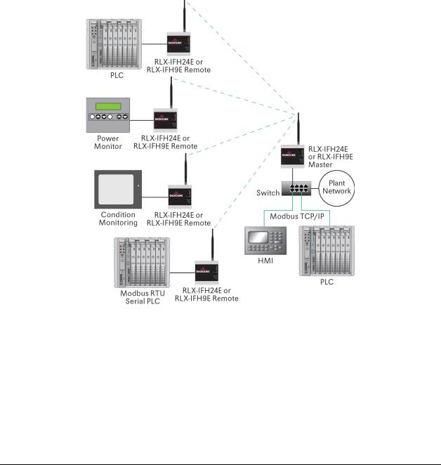
The following illustration shows how a radio network of RLX-IFH24E radios could be deployed to connect a variety of PLCs using a variety of industrial protocols. You could deploy a similar network of RLX-IFH9E radios.
The next important issue is how to link the radios. Unless the radios are very close together, you must make sure that each pair of radio antennas in the network has a line of sight between them. In other words, you must be able to see from one antenna to another, either with the naked eye or binoculars.
If a line of sight does not exist between antennas, you must choose a site for installing a repeater radio, which will create a bridge between the radio antennas. As part of your planning, you may need to conduct a site survey. ProSoft Technology can perform this survey, you can do it yourself, or you can hire a surveyor.
ProSoft Technology, Inc. |
Page 19 of 109 |
November 19, 2013 |
|

Start Here |
RLX-IFHE ♦ RadioLinx Industrial Wireless |
User Manual |
RadioLinx® Industrial Frequency Hopping Ethernet Radios |
|
|
The simplest way to design the physical network of radios, antennas, connectors, cables, amplifiers and other accessories, is to use ProSoft Wireless Designer (page 21). This application determines your hardware needs based on your answers to a few questions, and then generates a Bill of Materials specifying all the components you will need for your installation.
Consider printing your network plan from ProSoft Wireless Designer for references as you configure your network in ControlScape FH.
Protect radios from direct exposure to weather, and provide an adequate, stable power source. Make sure that your plan complies with the radio’s power requirements (page 56) and cable specifications (page 59, page 16, page 38, page 17).
Important: Radios and antennas must be located at least 8 inches (20 cm) away from personnel.
1.5.1 Installation Questions
Answer the following questions to make your installation easier, and to familiarize yourself with your system and what you want to do.
How many radios in your network?
Static IP Address, Subnet Mask and Gateway addresses for each RadioLinx device
Connection to an existing wired or wireless Ethernet network, either directly from the PC, or through an Ethernet switch or hub
Master ID |
Repeater ID |
Remote ID |
|
|
|
Locations
Is there a Line of Sight between them?
Selected the appropriate antennas for your network?
What type of network protocols do you need to support?
What type of cable connections do your network devices require?
Page 20 of 109 |
ProSoft Technology, Inc. |
|
November 19, 2013 |
RLX-IFHE ♦ RadioLinx Industrial Wireless |
Start Here |
RadioLinx® Industrial Frequency Hopping Ethernet Radios |
User Manual |
|
|
1.5.2 ProSoft Wireless Designer
ProSoft Wireless Designer simplifies the task of specifying a ProSoft Wireless installation, and provides a variety of views containing an accurate description of each site in a wireless network, including:
Visual diagram of site layout
Location (latitude/longitude, based on GPS coordinates)
Radio type, frequency range, and country-specific channel and power requirements
Length, type and estimated signal loss for cables
Required accessories, including lightning protection, cable adaptors and antennas
Complete parts list
Use ProSoft Wireless Designer when conducting a site audit for a customer, and then provide the customer with a complete list of components and a detailed description for each site and link. Customers can use this information to understand and visualize their network, and provide necessary information for technical support and maintenance.
Contains a database of all currently available RadioLinx radios, antennas, cables, connectors and accessories
Exports Parts List, Site and Link Details, and Wizard settings into a variety of common file formats, for import into applications such as spreadsheets, databases and word processors
Checks wireless link feasibility based on path length and recommended accessories
Predicts signal strength based on distance, local regulations and hardware choices
Fully documents your ProSoft Wireless network plan
Functional Specifications
The ProSoft WirelessN Discovery Tool supports the following network discovery and monitoring activities:
Discover and view the list of radios in the network
Display graphically the current network topology and display parent-child links between various radios in the network
Scan the network on demand
Save and load network snapshots
Upload and download configuration files to/from radio devices
Upgrade Radio firmware
ProSoft Technology, Inc. |
Page 21 of 109 |
November 19, 2013 |
|

Start Here |
RLX-IFHE ♦ RadioLinx Industrial Wireless |
User Manual |
RadioLinx® Industrial Frequency Hopping Ethernet Radios |
|
|
System Requirements
ProSoft WirelessN Discovery Tool is designed for computers running Microsoft Windows and Microsoft .NET Framework version 3.0 or newer.
Minimum hardware requirements are:
400 MHz or faster Pentium PC
128 MB RAM
CD-ROM drive
280 MB available hard drive space
The Microsoft .NET Framework version 3.0 is not supported on Windows 95, Windows NT 4, or Windows 3.x.
It is highly recommended for all platforms that you upgrade to the latest Windows Service Pack and install all critical updates available from Microsoft to ensure the best compatibility and security.
Page 22 of 109 |
ProSoft Technology, Inc. |
|
November 19, 2013 |
RLX-IFHE ♦ RadioLinx Industrial Wireless |
Start Here |
RadioLinx® Industrial Frequency Hopping Ethernet Radios |
User Manual |
|
|
1.6Configuring the Radios
Configuration of your RLX-IFHE radios consists of the following steps:
Start ControlScape FH (page 23)
Plug In the Cables (page 38)
Set Up the Network (page 24)
Set Up the Master Radio (page 35)
Add Remote Radios (page 40)
Add Repeaters (page 41)
Graphically Define the RF link (page 43)
Save the Network Configuration (page 45)
Save the Radio Configuration (page 39)
1.6.1 Start ControlScape FH
You will use an application (software program) called ControlScape FH to configure the RLX-IFHE radios and the radio network. If you have not already installed ControlScape FH, please do so now. Refer to Install ControlScape FH Configuration Software (page 18) for information on how to install the program.
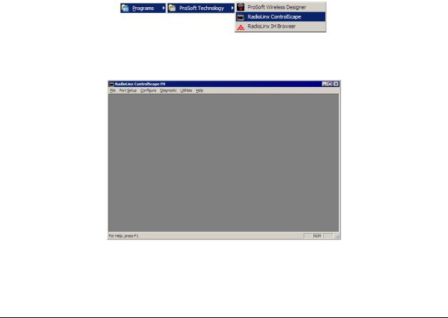
To start ControlScape
1Click the Start button, and then choose Programs
2In the Programs menu, navigate to the ProSoft Technology folder, and then choose RadioLinx ControlScape FH.
3Allow a few moments for the program to load. When the program has finished loading, you will see a screen like this:
ProSoft Technology, Inc. |
Page 23 of 109 |
November 19, 2013 |
|
Start Here |
RLX-IFHE ♦ RadioLinx Industrial Wireless |
User Manual |
RadioLinx® Industrial Frequency Hopping Ethernet Radios |
|
|
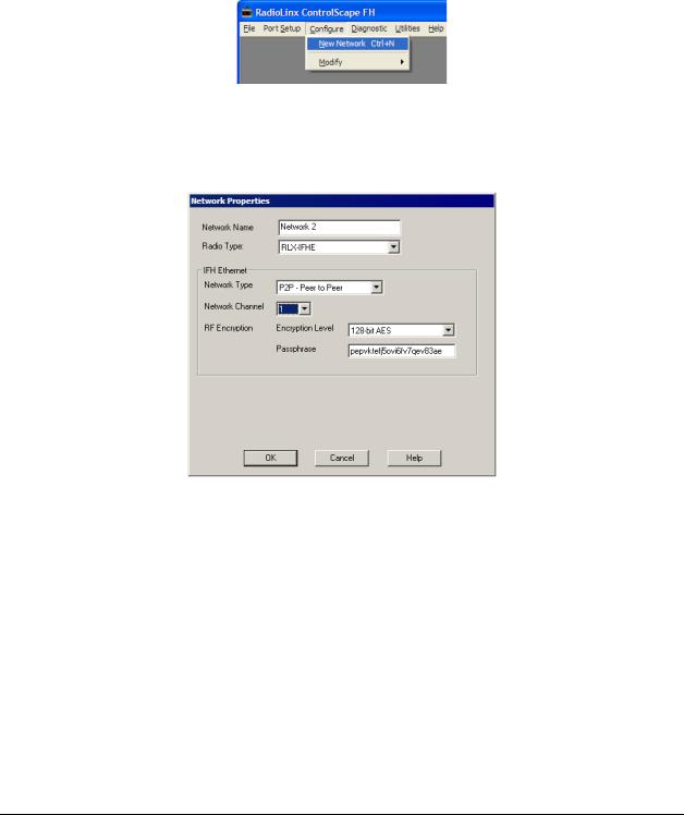
1.6.2 Set Up the Network
From the ControlScape FH Main Menu, select:
Configure
o New Network
A Network Properties dialog box is displayed where the basic parameters of the new network are defined. The items on this dialog box depend on what type of radio you select. The following example shows a RadioLinx IFHE (Industrial Frequency Hopping Ethernet) radio.
Page 24 of 109 |
ProSoft Technology, Inc. |
|
November 19, 2013 |

RLX-IFHE ♦ RadioLinx Industrial Wireless |
Start Here |
RadioLinx® Industrial Frequency Hopping Ethernet Radios |
User Manual |
|
|
Network Types - IFH Radios
Note: Available network types depend on the type of radio you are configuring. Not all network types are available on all radios. Only the SSE and PTP network types can be chosen for new networks. ControlScape still supports all of the legacy network types for users with networks of those types. The SSE type is replacing those networks as it provides the flexibility of the E2E and P2P network types with the performance of the PMP network type or better.
IFH Radios
P2P - Peer to Peer (page 27)
PMP - Point to Multipoint (page 28)
E2E - Everyone to Everyone (page 28)
PTP - Point to Point (page 30)
SSE - Smart Switched Ethernet (page 33)
Note: There is only one Master radio for each network.
|
|
|
|
|
|
|
|
ProSoft Technology, Inc. |
Page 25 of 109 |
||
November 19, 2013 |
|
|
|

Start Here |
RLX-IFHE ♦ RadioLinx Industrial Wireless |
User Manual |
RadioLinx® Industrial Frequency Hopping Ethernet Radios |
|
|
SNMP Interface
The RLX-IFHxE radios also support the Simple Network Management Protocol (SNMP). This interface can be used to get status information or configure the radio using a third party SNMP client. The radio acts as a server to respond to requests sent by the user. The standard method for providing the set of possible data that can be retrieved and settings that can be modified is through a specially formatted text file with the extension .MIB. The MIB file for the RLX-IFHxE radios is located on the CD that ships with your product and on the ProSoft webpage for the RLX-IFHxE product.
SNMP uses a series of numbers separated by a decimal point to indicate the unique value that is being accessed. These are called Object Identifiers (OIDs). While the SNMP standard specifies certain generic OIDs, the most useful are usually the custom OIDs for a product. The information in the MIB file describes the custom OIDs to which the RLX-IFHxE SNMP server will respond. This information includes the OID number and name, whether that OID is read-only or read/write, the type of the value that this OID will retrieve or can be set, and sometimes information about what that value means. The file is setup hierarchically with groups of OIDs contained within a higher level OID. Each OID specifies a higher order name and a number. The higher order name identifies the series of numbers before the final number. The full OID would then be that series along with the number specified in the OID description.
This is an example entry: radioOperationMode OBJECT-TYPE
SYNTAX INTEGER { master(0), repeater(1), remote(2) } ACCESS read-write
STATUS mandatory
DESCRIPTION "Radio Operation Mode: 0 - Master 1 - Repeater 2 - Slave."
::= { radioConfig 2 }
radioOperationMode is the name of the OID.
The values it accepts and returns is an INTEGER. The valid values of the integer are 0, 1, and 2 which have a meaning of master, repeater, and remote respectively.
This OID allows both read and write capability.
The last line specifies the OID number series. radioConfig is the higher level OID to which radioOperationMode belongs. 2 is the number for this OID within the radioConfig group. The radioConfig group is described in a different entry.
Page 26 of 109 |
ProSoft Technology, Inc. |
|
November 19, 2013 |
RLX-IFHE ♦ RadioLinx Industrial Wireless |
Start Here |
RadioLinx® Industrial Frequency Hopping Ethernet Radios |
User Manual |
|
|
The SNMP standard provides a special OID group for custom OIDs. This special OID group is named ‘enterprises’. The MIB file only contains OIDs within this group. The MIB file, while legible to humans, is organized for use by a program and can be difficult to follow by just looking at the contents of the file. This is due to the fractured format of the information. As in the example, if you want to determine an OID number series, you look at the OID specification for the entry, but it only gives you the number of the last digit. To complete the number series, it would require finding each levels entry and value one at a time in the MIB (or in the SNMP standard, for OID numbers at the enterprises level or higher).
In addition to the OIDs, there are a couple of parameters that are necessary in order to successfully communicate with the radio over SNMP. For SNMPv1 there are community names that are required to access the RLX-IFHxE over
SNMP. For SNMPv3, a username and password are required. See the following table for this information.
SNMP Parameter |
Value |
|
|
Read Only Community Name |
Public |
|
|
Write Community Name |
Private |
|
|
SNMP v3 Username |
Prosoft |
|
|
SNMPv3 Password |
Password |
|
|
Peer to Peer Networks
Peer-to-Peer (P2P) supports communication (through the Master) between two or more remote units. Each radio can be configured to send its messages to one other radio, or to broadcast to all radios in the network.
In the following illustration, the master radio is configured to broadcast to both radios. Each remote radio is configured to send data back to the master.
ProSoft Technology, Inc. |
Page 27 of 109 |
November 19, 2013 |
|

Start Here |
RLX-IFHE ♦ RadioLinx Industrial Wireless |
User Manual |
RadioLinx® Industrial Frequency Hopping Ethernet Radios |
|
|
Point to Multipoint Networks
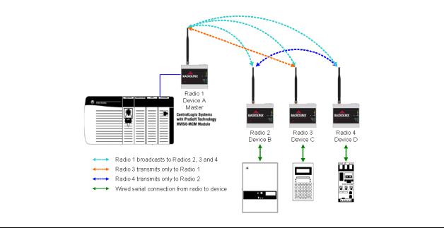
Point to Multipoint configuration creates the network to broadcast data from the Master radio to the other radios in the network. All of the other radios return their data to the Master radio.
A Point to Multipoint network is well suited for a polled network such as Modbus RTU, DF1 or Modbus TCP/IP. Communications from remote radios is directed back to master radio. Master radio broadcasts to all other radios.
In the following illustration, the Master radio is configured to broadcast data to Radios 2, 3 and 4.
Page 28 of 109 |
ProSoft Technology, Inc. |
|
November 19, 2013 |

RLX-IFHE ♦ RadioLinx Industrial Wireless |
Start Here |
RadioLinx® Industrial Frequency Hopping Ethernet Radios |
User Manual |
|
|
Everyone to Everyone Networks
Everyone-to-Everyone (E2E) configuration creates a network where all units communicate with all other units, through the Master. Note that this mode is very bandwidth-intensive, because all data is transmitted to all radios.
In the following illustration, each radio broadcasts to all the other radios.
ProSoft Technology, Inc. |
Page 29 of 109 |
November 19, 2013 |
|

Start Here |
RLX-IFHE ♦ RadioLinx Industrial Wireless |
User Manual |
RadioLinx® Industrial Frequency Hopping Ethernet Radios |
|
|
Point to Point Networks
Point-to-Point configuration transfers data between two radios (points) in the network. In the network shown below, the Master Radio and Radio 4 transfer data between each other. Radios 2 and 3 only act as bridges to get the data between them.
Page 30 of 109 |
ProSoft Technology, Inc. |
|
November 19, 2013 |
 Loading...