


MVI69E-LDM
"C" Programmable
Linux Application Development
Module
August 21, 2014
DEVELOPER'S MANUAL

Your Feedback Please
We always want you to feel that you made the right decision to use our products. If you have suggestions, comments, compliments or complaints about our products, documentation, or support, please write or call us.
ProSoft Technology
5201 Truxtun Ave., 3rd Floor Bakersfield, CA 93309
+1 (661) 716-5100
+1 (661) 716-5101 (Fax) www.prosoft-technology.com support@prosoft-technology.com
© 2014 ProSoft Technology, Inc. All rights reserved.
MVI69E-LDM Developer's Manual
August 21, 2014
ProSoft Technology®, is a registered copyright of ProSoft Technology, Inc. All other brand or product names are or may be trademarks of, and are used to identify products and services of, their respective owners.
In an effort to conserve paper, ProSoft Technology no longer includes printed manuals with our product shipments. User Manuals, Datasheets, Sample Ladder Files, and Configuration Files are provided on the enclosed DVD and are available at no charge from our web site: http://www.prosoft-technology.com
Important Installation Instructions
Power, Input, and Output (I/O) wiring must be in accordance with Class I, Division 2 wiring methods, Article 501-4 (b) of the National Electrical Code, NFPA 70 for installation in the U.S., or as specified in Section 18-1J2 of the Canadian Electrical Code for installations in Canada, and in accordance with the authority having jurisdiction. The following warnings must be heeded:
WARNING - EXPLOSION HAZARD - SUBSTITUTION OF COMPONENTS MAY IMPAIR SUITABILITY FOR CLASS I, DIV. 2;
WARNING - EXPLOSION HAZARD - WHEN IN HAZARDOUS LOCATIONS, TURN OFF POWER BEFORE REPLACING OR WIRING MODULES
WARNING - EXPLOSION HAZARD - DO NOT DISCONNECT EQUIPMENT UNLESS POWER HAS BEEN SWITCHED OFF OR THE AREA IS KNOWN TO BE NON-HAZARDOUS.
THIS DEVICE SHALL BE POWERED BY CLASS 2 OUTPUTS ONLY.
MVI (Multi Vendor Interface) Modules
WARNING - EXPLOSION HAZARD - DO NOT DISCONNECT EQUIPMENT UNLESS POWER HAS BEEN SWITCHED OFF OR THE AREA IS KNOWN TO BE NON-HAZARDOUS.
AVERTISSEMENT - RISQUE D'EXPLOSION - AVANT DE DÉCONNECTER L'ÉQUIPEMENT, COUPER LE COURANT OU S'ASSURER QUE L'EMPLACEMENT EST DÉSIGNÉ NON DANGEREUX.
Warnings, Specification, and Certifications
North America Warnings
AWarning - Explosion Hazard - Substitution of components may impair suitability for Class I, Division 2.
BWarning - Explosion Hazard - When in Hazardous Locations, turn off power before replacing or rewiring modules.
CWarning - Explosion Hazard - Do not disconnect equipment unless power has been switched off or the area is known to be non-hazardous.
DSuitable for use in Class I, Division 2 Groups A, B, C and D Hazardous Locations or Non-Hazardous Locations only.
EThe subject devices are powered by a Switch Model Power Supply (SMPS) that has a regulated output voltage of 5 VDC.
ATEX Warnings and Conditions of Safe Usage:
Power, Input, and Output (I/O) wiring must be in accordance with the authority having jurisdiction
AWarning - Explosion Hazard - When in hazardous locations, turn off power before replacing or wiring modules.
BWarning - Explosion Hazard - Do not disconnect equipment unless power has been switched off or the area is known to be non-hazardous.
CThese products are intended to be mounted in an IP54 enclosure. The devices shall provide external means to prevent the rated voltage being exceeded by transient disturbances of more than 40%. This device must be used only with ATEX certified backplanes.
DDO NOT OPEN WHEN ENERGIZED.
CPU, Memory, and OS Specifications
CPU: 400MHz ARM9 G20
Operating System: Linux (kernel 2.6.33.7)
Linux Distribution: BusyBox
System Memory: 64MB SDRAM
Flash Memory: 256MB NAND Flash
General Specifications
Backplane Current Load: 500 mA @ 5 VDC; 3mA @ 24 VDC
Operating Temperature: 0 to 60°C (32 to 140°F)
Storage Temperature: -40 to 85°C (-40 to 185°F)
Shock: 30g non-operational; 15g non-operational; Vibration: 5 g from 10 to 150 Hz
Relative Humidity: 5% to 95% (without condensation)
LED Indicators: ETH - Application driven, P1 Application Driven, P2 Application driven, CFG - Application driven, BP - Application driven, OK - Application driven
Ethernet Ports
1 Ethernet port
10/100 Mbps
RJ45 connector
Link and Activity indicators
Auto-sensing crossover cable detection
Serial Ports
Full hardware handshaking control provides radio, modem, and multi-drop support.
2 Serial Application ports: RJ45 (DB-9M with supplied adapter cable)
Configurable RS-232 hardware handshaking
500V Optical isolation from backplane
RS-232, RS-422, RS-485 (software configurable by the end user)
Rx (Receive) and Tx (Transmit) LEDs, each port

Agency Approvals and Certifications
ATEX, Zone 2
CE
CSA CB Safety
cULus; Class 1, Div 2
MVI69E-LDM ♦ "C" Programmable |
Contents |
Linux Application Development Module |
Developer's Manual |
|
|
Contents
Your Feedback Please........................................................................................................................ |
2 |
Important Installation Instructions ....................................................................................................... |
2 |
MVI (Multi Vendor Interface) Modules ................................................................................................ |
2 |
Warnings, Specification, and Certifications ........................................................................................ |
3 |
1 |
Preparing the MVI69E-LDM Module |
9 |
||
|
|
|
|
|
|
1.1 |
MVI69E-LDM Introduction ......................................................................................... |
9 |
|
|
1.2 |
System Requirements ............................................................................................. |
10 |
|
|
1.3 |
Package Contents ................................................................................................... |
11 |
|
|
1.4 |
Jumper Locations and Settings ............................................................................... |
11 |
|
|
1.4.1 |
Setup Jumper .......................................................................................................... |
12 |
|
|
1.4.2 |
Port 1 and Port 2 Jumpers ...................................................................................... |
12 |
|
|
1.5 |
Installing and Connecting the Module ..................................................................... |
12 |
|
|
1.5.1 |
Installing the Module in the Chassis........................................................................ |
13 |
|
|
1.5.2 |
Making Configuration Port Connections.................................................................. |
16 |
|
|
1.5.3 |
Enabling and Disabling the Console Port................................................................ |
20 |
|
|
1.6 |
Establishing Module Communications .................................................................... |
24 |
|
|
1.7 |
Resetting the Module .............................................................................................. |
27 |
|
|
1.8 |
Important Information Before Development ............................................................ |
29 |
|
2 |
Development Environment |
31 |
||
|
|
|
|
|
|
2.1 |
Setup ....................................................................................................................... |
31 |
|
|
2.2 |
Starting Eclipse ....................................................................................................... |
34 |
|
|
2.2.1 |
Building a Project .................................................................................................... |
34 |
|
|
2.2.2 |
Compiling and Linking ............................................................................................. |
35 |
|
|
2.2.3 |
Downloading the Application with FTP.................................................................... |
36 |
|
|
2.2.4 |
Creating an Application Image ................................................................................ |
36 |
|
|
2.2.5 |
Downloading the Image with Firmware Update ...................................................... |
37 |
|
3 |
Understanding the MVI69E-LDM API |
39 |
||
|
|
|
|
|
|
3.1 |
API Library............................................................................................................... |
39 |
|
|
3.1.1 |
Header File .............................................................................................................. |
39 |
|
|
3.1.2 |
Sample Code........................................................................................................... |
39 |
|
|
3.1.3 |
CompactLogix Tag Naming Conventions................................................................ |
39 |
|
|
3.2 |
MVI69E-LDM Development Tools........................................................................... |
40 |
|
|
3.3 |
CIP API Architecture ............................................................................................... |
41 |
|
|
3.4 |
Backplane Device Driver ......................................................................................... |
42 |
|
4 |
Sample Code |
43 |
|||
|
|
|
|
|
|
|
|
4.1 |
Establishing a Console Connection |
........................................................................ 44 |
|
|
|
4.1.1 |
Physically Connect to the Module ........................................................................... |
44 |
|
|
|
4.1.2 |
Configuring Serial Communication.......................................................................... |
44 |
|
|
|
4.1.3 |
Setting Up ControlLogix 5000 ................................................................................. |
45 |
|
|
|
4.2 |
Sample Tutorials ..................................................................................................... |
46 |
|
|
|
|
|
|
|
ProSoft Technology, Inc. |
|
Page 5 of 130 |
|||
August 21, 2014 |
|
|
|
||
Contents |
|
|
MVI69E-LDM ♦ "C" Programmable |
|||
Developer's Manual |
|
Linux Application Development Module |
||||
|
|
|
|
|
|
|
|
|
4.2.1 |
Ethernet Sample ..................................................................................................... |
|
46 |
|
|
|
4.2.2 |
Serial Sample.......................................................................................................... |
|
49 |
|
|
|
4.2.3 |
LED Sample............................................................................................................ |
|
50 |
|
|
|
4.2.4 |
Backplane Sample .................................................................................................. |
|
51 |
|
|
|
4.3 |
Application Tutorials ............................................................................................... |
|
52 |
|
|
|
4.3.1 |
Ethernet Application................................................................................................ |
|
52 |
|
|
|
4.3.2 |
Serial Application .................................................................................................... |
|
58 |
|
5 |
API Functions |
|
67 |
|||
|
|
|
|
|
|
|
|
|
5.1 |
CIP API Initialization Functions............................................................................... |
|
68 |
|
|
|
MVI69_Open ............................................................................................................................... |
|
68 |
||
|
|
MVI69_OpenNB .......................................................................................................................... |
|
69 |
||
|
|
MVI69_Close ............................................................................................................................... |
|
70 |
||
|
|
MVI69_GetIOConfig .................................................................................................................... |
|
71 |
||
|
|
MVI69_SetIOConfig .................................................................................................................... |
|
72 |
||
|
|
5.2 |
Direct I/O Access .................................................................................................... |
|
73 |
|
|
|
MVI69_ReadOutputImage........................................................................................................... |
|
73 |
||
|
|
MVI69_WriteInputImage.............................................................................................................. |
|
74 |
||
|
|
5.3 |
Messaging............................................................................................................... |
|
75 |
|
|
|
MVI69_GetMsgRequestFromBp ................................................................................................. |
|
75 |
||
|
|
MVI69_SendMsgResponseToBp ................................................................................................ |
|
77 |
||
|
|
5.4 |
Synchronization ...................................................................................................... |
|
79 |
|
|
|
MVI69_WaitForInputScan ........................................................................................................... |
|
79 |
||
|
|
MVI69_WaitForOutputScan ........................................................................................................ |
|
80 |
||
|
|
5.5 |
Serial Ports ............................................................................................................. |
|
81 |
|
|
|
MVI69_GetSerialConfig............................................................................................................... |
|
81 |
||
|
|
MVI69_SetSerialConfig ............................................................................................................... |
|
83 |
||
|
|
5.6 |
Miscellaneous Functions ........................................................................................ |
|
84 |
|
|
|
MVI69_GetVersionInfo ................................................................................................................ |
|
84 |
||
|
|
MVI69_GetModuleInfo ................................................................................................................ |
|
85 |
||
|
|
MVI69_SetModuleInfo................................................................................................................. |
|
86 |
||
|
|
MVI69_GetScanMode ................................................................................................................. |
|
87 |
||
|
|
MVI69_GetScanCounter ............................................................................................................. |
|
88 |
||
|
|
MVI69_SetLED............................................................................................................................ |
|
89 |
||
|
|
MVI69_GetSetupJumper............................................................................................................. |
|
90 |
||
6 |
Cable Connections |
|
91 |
|||
|
|
|
|
|
|
|
|
|
6.1 |
RS-232 Configuration/Debug Port .......................................................................... |
|
91 |
|
|
|
6.2 |
RS-232 Application Port(s) .................................................................................... |
|
92 |
|
|
|
6.2.1 |
RS-232: Modem Connection (Hardware Handshaking Required) |
......................... 92 |
||
|
|
6.2.2 |
RS-232: Null Modem Connection (Hardware Handshaking) .................................. |
93 |
||
|
|
6.2.3 |
RS-232: Null Modem Connection (No Hardware Handshaking) ............................ |
93 |
||
|
|
6.3 |
RS-422.................................................................................................................... |
|
94 |
|
|
|
6.4 |
RS-485 Application Port(s) ..................................................................................... |
|
94 |
|
|
|
6.4.1 |
RS-485 and RS-422 Tip ......................................................................................... |
|
95 |
|
|
|
6.5 |
DB9 to RJ45 Adaptor (Cable 14) ............................................................................ |
|
95 |
|
7 |
Open Source Licensing |
|
97 |
|||
|
|
|
|
|
|
|
|
|
7.1 |
GNU Public License................................................................................................ |
|
98 |
|
|
|
7.2 |
Eclipse Public License .......................................................................................... |
|
111 |
|
|
|
|
|
|
||
Page 6 of 130 |
|
ProSoft Technology, Inc. |
||||
|
|
|
|
|
August 21, 2014 |
|

MVI69E-LDM ♦ "C" Programmable |
Contents |
|
Linux Application Development Module |
Developer's Manual |
|
7.3 |
Python Public License ........................................................................................... |
115 |
7.4 |
GCC Public License .............................................................................................. |
120 |
8 |
Support, Service & Warranty |
123 |
8.1 |
Contacting Technical Support ............................................................................... |
123 |
8.2 |
Warranty Information............................................................................................. |
124 |
9 |
Glossary of Terms |
125 |
Index |
129 |
|
ProSoft Technology, Inc. |
Page 7 of 130 |
August 21, 2014 |
|

Contents |
MVI69E-LDM ♦ "C" Programmable |
Developer's Manual |
Linux Application Development Module |
|
|
Page 8 of 130 |
ProSoft Technology, Inc. |
|
August 21, 2014 |

MVI69E-LDM ♦ "C" Programmable |
Contents |
||
Linux Application Development Module |
Developer's Manual |
||
1 |
Preparing the MVI69E-LDM Module |
|
|
|
In This Chapter |
|
|
|
|
MVI69E-LDM Introduction....................................................................... |
9 |
|
|
System Requirements............................................................................ |
10 |
|
|
Package Contents ................................................................................. |
11 |
|
Jumper Locations and Settings.............................................................. |
11 |
|
|
Installing and Connecting the Module .................................................... |
12 |
|
|
|
Establishing Module Communications ................................................... |
24 |
|
|
Resetting the Module ............................................................................. |
27 |
|
Important Information Before Development ........................................... |
29 |
|
1.1MVI69E-LDM Introduction
The MVI69E-LDM module is a CompactLogix backplane-compatible module that allows Rockwell Automation CompactLogix processors to interface with relatively any Ethernet or Serial device. With the supplied development tools and example applications, you are the developer that controls exactly what this module can and cannot do.
ProSoft Technology's Linux Development modules make it possible for you to easily develop and deploy C/C++ applications that interface with Bar Code Scanners, Legacy ASCII protocols, Terminal Port Emulation, Printer Drivers (Alarm/Status printer), or any other device requiring custom or proprietary Ethernet and Serial communications.
This document provides the information you need to develop application programs for the MVI69E-LDM module.
This document assumes you are familiar with software development in the Linux environment using the C/C++ programming languages. This document also assumes that you are familiar with Rockwell Automation programmable controllers and the CompactLogix platform.
ProSoft Technology, Inc. |
Page 9 of 130 |
August 21, 2014 |
|

Contents |
MVI69E-LDM ♦ "C" Programmable |
Developer's Manual |
Linux Application Development Module |
|
|
You should be familiar with the following terms:
API |
Application Programming Interface |
|
|
Backplane |
Refers to the electrical interface or bus to which modules connect when |
|
inserted into the rack. The MVI69E-LDM communicates with the control |
|
processor(s) through the CompactLogix backplane. |
|
|
CIP |
Control and Information Protocol. This is the messaging protocol used |
|
for communications over the CompactLogix backplane. |
|
|
Connection |
A logical binding between two objects. A connection allows more |
|
efficient use of bandwidth because the messaging path is not included |
|
after the connection is established. |
|
|
Consumer |
A destination for data. |
|
|
Library |
Refers to the library file (DLL) that contains the API functions. The |
|
library must be linked with the developer's application code to create |
|
the final executable program. |
|
|
Originator |
A client that establishes a connection path to a target. |
|
|
Producer |
A source of data. |
|
|
Target |
The end-node to which a connection is established by an originator. |
|
|
1.2System Requirements
The MVI69E-LDM module requires the following hardware and software components:
Rockwell Automation CompactLogix processor (firmware version 18 or greater depending on processor type) with compatible power supply and one free slot in the rack for the module. The module requires 5 VDC power
Rockwell Automation RSLogix 5000 software
Rockwell Automation RSLinx communication software version 2.51 or greater
Pentium II 450 MHz minimum. Pentium III 733 MHz or greater recommended
Supported operating systems:
o Microsoft Windows 7 Professional (32 or 64-bit) o Microsoft Windows Vista
o Microsoft Windows XP Professional with Service Pack 1 or 2
o Microsoft Windows 2000 Professional with Service Pack 1, 2, or 3 o Microsoft Windows Server 2003
128 MB RAM (minimum), 256 MB of RAM recommended
100 MB of free hard disk space (or more based on application requirements)
256-color VGA graphics adapter, 800 x 600 minimum resolution (True Color 1024 x 768
recommended)
DVD drive
Note: The Hardware and Operating System requirements in this list are the minimum recommended to install and run software provided by ProSoft Technology. Other third party applications may have different requirements. Refer to the documentation for any third party applications.
|
|
|
|
|
|
|
|
Page 10 of 130 |
ProSoft Technology, Inc. |
|
|
|
|
August 21, 2014 |
|
MVI69E-LDM ♦ "C" Programmable |
Contents |
Linux Application Development Module |
Developer's Manual |
|
|
1.3Package Contents
Your MVI69E-LDM package includes:
RJ45 to DB-9M cables for each serial port
(2) DB9 to screw terminal adapter
Ethernet Straight-Thru Cable
Null Modem Cable
You can download all documentation, sample code, and sample ladder logic from our website for free (www.prosoft-technology.com/ldmdevkit).
If any of these components are missing, please contact ProSoft Technology Support.
Not Shipped with Unit
LDMdevKit - Linux Development Module Development Kit (Available for purchase from ProSoft Technology and must be ordered separately.)
1.4Jumper Locations and Settings
Each module has three jumpers:
Setup
Port 1
Port 2
ProSoft Technology, Inc. |
Page 11 of 130 |
August 21, 2014 |
|
Contents |
MVI69E-LDM ♦ "C" Programmable |
Developer's Manual |
Linux Application Development Module |
|
|
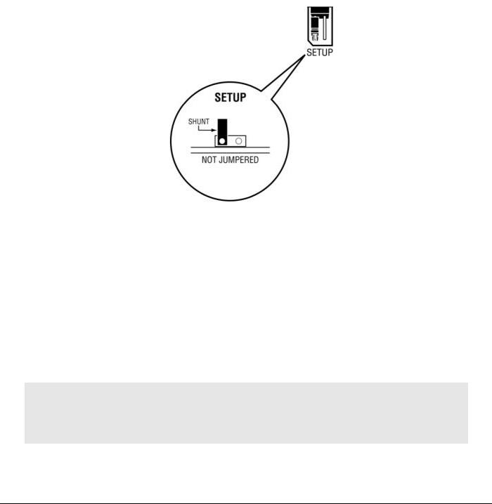
1.4.1 Setup Jumper
The Setup Jumper acts a write protection for the module's firmware. In "write-protected" mode, the setup pins are not connected which prevents the module's firmware from being overwritten.
The module is shipped with the Setup Jumper OFF. If you need to update the firmware or run a module rescue (recovery), apply the setup shunt over both pins.
1.4.2 Port 1 and Port 2 Jumpers
These jumpers, located at the bottom of the module, aid in configuring the port settings to RS-232, RS-422, or RS-485. The "RS-232", "RS-485", and "RS-422" labels are there for convenience. The jumpers simply send a high/low signal when jumped or not jumped. The jumper configuration is read by the API, and the application code must change the appropriate port settings to the required mode (232, 485, 422).
1.5Installing and Connecting the Module
If you have not already done so, please install and configure your CompactLogix processor and power supply. Refer to the Rockwell Automation product documentation for installation instructions.
Warning: You must follow all safety instructions when installing this or any other electronic devices. Failure to follow safety procedures could result in damage to hardware or data, or even serious injury or death to personnel. Refer to the documentation for each device you plan to connect to verify that suitable safety procedures are in place before installing or servicing this device.
After verifying proper jumper placement, insert the module into the CompactLogix chassis. Use the same technique recommended by Rockwell Automation to remove and install CompactLogix modules.
Page 12 of 130 |
ProSoft Technology, Inc. |
|
August 21, 2014 |

MVI69E-LDM ♦ "C" Programmable |
Contents |
Linux Application Development Module |
Developer's Manual |
|
|
1.5.1 Installing the Module in the Chassis
You can install or remove CompactLogix system components while chassis power is applied and the system is operating. However, please note the following warning.
Warning: When you insert or remove the module while backplane power is on, an electrical arc can cause personal injury or property damage by sending an erroneous signal to your system's actuators. This can cause unintended machine motion or loss of process control. Electrical arcs may also cause an explosion they occur in a hazardous environment. Verify that power is removed, or that the area is non-hazardous before proceeding. Repeated electrical arcing causes excessive wear to contacts on both the module and its mating connector. Worn contacts may create electrical resistance that can affect module operation.
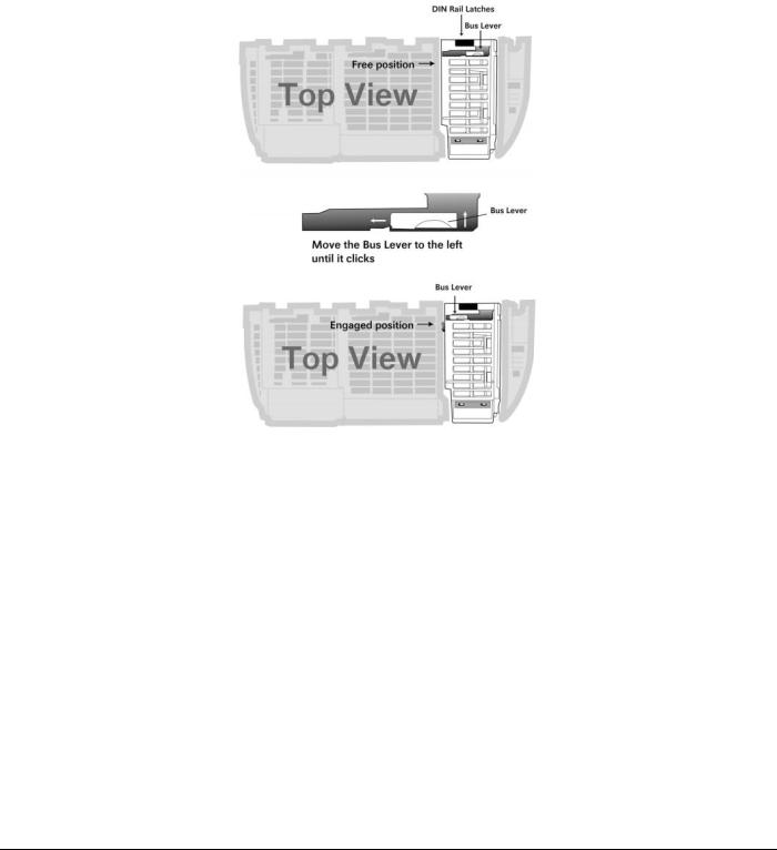
1Align the module using the upper and lower tongue-and_groove slots with the adjacent module and slide forward in the direction of the arrow.
ProSoft Technology, Inc. |
Page 13 of 130 |
August 21, 2014 |
|
Contents |
MVI69E-LDM ♦ "C" Programmable |
Developer's Manual |
Linux Application Development Module |
|
|
2Move the module back along the tongue-and-groove slots until the bus connectors on the MVI69E module and the adjacent module line up with each other. Push the module's bus lever back slightly to clear the positioning tab and move it firmly to the left until it clicks. Ensure that it is locked firmly into place.
3 Close all DIN-rail latches.
Page 14 of 130 |
ProSoft Technology, Inc. |
|
August 21, 2014 |

MVI69E-LDM ♦ "C" Programmable |
Contents |
Linux Application Development Module |
Developer's Manual |
|
|
4Press the DIN-rail mounting area of the controller against the DIN-rail. The latches momentarily open and lock into place.
Module inserted.
ProSoft Technology, Inc. |
Page 15 of 130 |
August 21, 2014 |
|
Contents |
MVI69E-LDM ♦ "C" Programmable |
Developer's Manual |
Linux Application Development Module |
|
|
1.5.2 Making Configuration Port Connections
You can communicate with the module via RS232 through the Console or through the Ethernet port using Telnet.
RS-232 Console
You access the Console through Serial Port 1. As a default, the RS-232 Console port is enabled. You can disable or enable this port. Refer to Enabling and Disabling the Console Port in the next section.
1Connect the RJ45 end of an RJ45 - DB9m cable (Cable 14) to the Serial Port 1 of the module.
2Connect one end of the Null Modem Cable (Cable 15) to the DB9m end Cable 14.
3Connect the other end of Cable 15 (null modem cable) to a serial port on your PC or laptop.
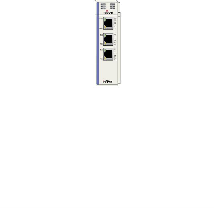
Ethernet Port
1The module contains a Telnet client which you can access through Ethernet Port 1 (Eth 1) as shown.
2Connect an Ethernet RJ45 cable to the Eth 1 port of the module and the other end to the Ethernet network switch.
Page 16 of 130 |
ProSoft Technology, Inc. |
|
August 21, 2014 |
MVI69E-LDM ♦ "C" Programmable |
Contents |
Linux Application Development Module |
Developer's Manual |
|
|
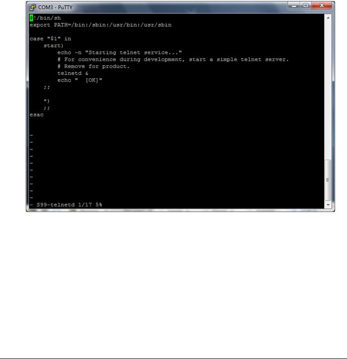
To enable or disable the Telnet port:
This example uses PuTTY, which you can download for free at from:
http://www.chiark.greenend.org.uk/~sgtatham/putty/download.html
1Start PuTTY.
2Open a PuTTY session as shown below. The following screenshot shows the Telnet Port enabled.
ProSoft Technology, Inc. |
Page 17 of 130 |
August 21, 2014 |
|
Contents |
MVI69E-LDM ♦ "C" Programmable |
Developer's Manual |
Linux Application Development Module |
|
|
To disable the Telnet port
1 Change to the s99-telnetd directory. Type:
cd\etc\init.d\S99-telnetd
2 List the files in the directory. Type:
ls
Page 18 of 130 |
ProSoft Technology, Inc. |
|
August 21, 2014 |

MVI69E-LDM ♦ "C" Programmable |
Contents |
Linux Application Development Module |
Developer's Manual |
|
|
3 Comment out the telnetd file.
4 To enable the port, simply un-comment the same line.
ProSoft Technology, Inc. |
Page 19 of 130 |
August 21, 2014 |
|
Contents |
MVI69E-LDM ♦ "C" Programmable |
Developer's Manual |
Linux Application Development Module |
|
|
1.5.3 Enabling and Disabling the Console Port
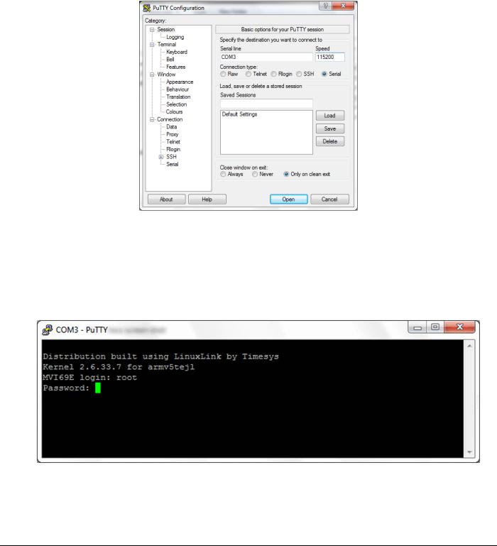
Establish a connection to the module. This example uses PuTTY. 1 Open PuTTY.
2Set SPEED to 115200.
3Set the SERIAL LINE to the appropriate COM port.
4Ensure that the CONNECTION TYPE is Serial.
5Click OPEN. The PuTTY session opens.
6Enter your login and password. MVI69E login: root
Password: password
Page 20 of 130 |
ProSoft Technology, Inc. |
|
August 21, 2014 |
MVI69E-LDM ♦ "C" Programmable |
Contents |
Linux Application Development Module |
Developer's Manual |
|
|
The following text appears: |
|
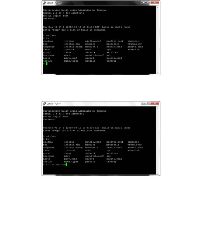
7 Change to the /etc directory. Type:
cd /etc
ProSoft Technology, Inc. |
Page 21 of 130 |
August 21, 2014 |
|
Contents |
MVI69E-LDM ♦ "C" Programmable |
Developer's Manual |
Linux Application Development Module |
|
|
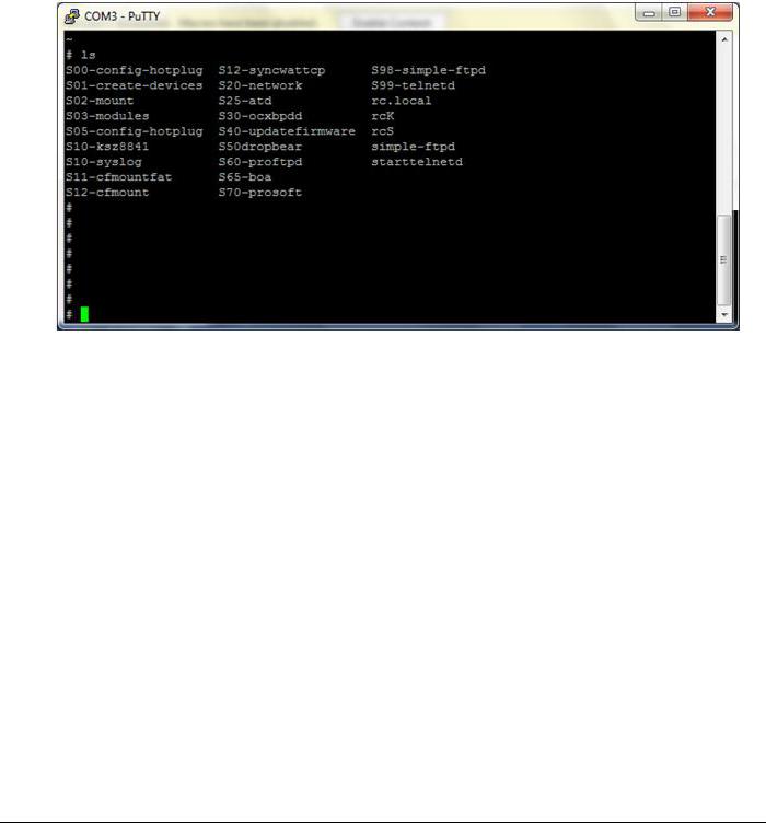
8 Type ls. The following appears: |
|
To enable the console port:
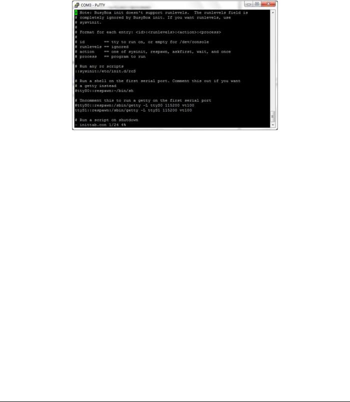
The inittab.con file configures the console.
Page 22 of 130 |
ProSoft Technology, Inc. |
|
August 21, 2014 |
MVI69E-LDM ♦ "C" Programmable |
Contents |
Linux Application Development Module |
Developer's Manual |
|
|
1Open the file in the vi editor. Type
vi inittab.con
2 Copy inittab.con file to the inittab file. Type
cp –f inittab.con inittab
3 Save the file and reboot the module.
To disable the console:
1Copy inittab.nocon file to the inittab file.
2Save the file and reboot the module.
ProSoft Technology, Inc. |
Page 23 of 130 |
August 21, 2014 |
|

Contents |
MVI69E-LDM ♦ "C" Programmable |
Developer's Manual |
Linux Application Development Module |
|
|
1.6Establishing Module Communications
Ensure that the module is firmly seated in the rack and that the cables connected to the module are secure. Ensure that power is applied.
Note: If you require information on cables and port pinouts, please refer to the section entitled Cable Connections (page 91) at the end of the manual.
RS-232 Console
If you are connected to Serial Port 1 (P1), establish communications with the module using the following procedure.
Note: The following procedure uses PuTTY to establish communications. You can use a different communication program.
1 Open PuTTY.
2Set SPEED to 115200.
3Set SERIAL LINE to the appropriate COM port.
4Ensure that CONNECTION TYPE is set to Serial.
5Click OPEN to open the PuTTY session.
6Enter your login and password: MVI69E login: root
Password: password
Page 24 of 130 |
ProSoft Technology, Inc. |
|
August 21, 2014 |

MVI69E-LDM ♦ "C" Programmable |
Contents |
Linux Application Development Module |
Developer's Manual |
|
|
Ethernet (Telnet)
You can communicate with the module through Ethernet Port 1 (Eth 1) using Telnet.
The Ethernet Port (Eth 1) on the module is programmed with eth0 set to IP 192.168.0.250 and a Subnet Mask of 255.255.255.0. In order for your PC or laptop to talk to the module, your PC or Laptop must be on the same subnet as the module. This means that you must temporarily change the IP address and subnet mask on your PC or laptop to match that of the module. You can then change the module's IP address to match your needs. Follow these steps or see http://windows.microsoft.com/en-us/windows/change-tcp-ip- settings#1TC=windows-7 http://windows.microsoft.com/en-us/windows/change-tcp-ip- settings#1TC=windows-7.
1Change the IP address of your PC or Laptop so it matches the subnet of the module. The following steps are for Windows 7.
a Change your IP address through the router. Consult your router documentation for
more information.
bChange your IP address through Windows Network Connections. Click START >
CONTROL PANEL > NETWORK AND SHARING CENTER.
cClick the CONNECTION link for the connection you want to change and choose
PROPERTIES.
dOn the Local Area Connection Properties dialog, select the connection you want to change (Internet Protocol Version 6 or Internet Protocol Version 4), and then click
PROPERTIES.
eIn the Internet Protocol Version 4 or 6 Properties dialog, click USE THE FOLLOWING IP
ADDRESS.
f Type in the IP address settings for the IP ADDRESS, SUBNET MASK, and DEFAULT
GATEWAY.
g Click OK to accept the changes and then close each of the dialog boxes.
2Ensure that an Ethernet cable is connected to Ethernet Port 1 (Eth 1) of the module, and the other end to the same Ethernet switch as your PC.
ProSoft Technology, Inc. |
Page 25 of 130 |
August 21, 2014 |
|
Contents |
MVI69E-LDM ♦ "C" Programmable |
Developer's Manual |
Linux Application Development Module |
|
|
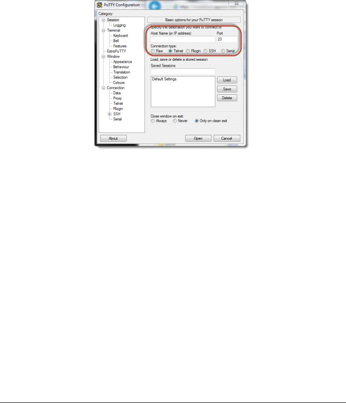
3 Use a program such as PuTTY to Telnet into the module.
4Select Telnet as the CONNECTION TYPE.
5Enter the IP ADDRESS (192.168.0.250).
6Port 23 should appear as the PORT number.
7Click OPEN to establish a connection.
8Log into the module.
There are two methods you can use to change the module's IP address. One is temporary for use in cases where you want to change the address long enough to make a quick change. The other is more permanent so that the module is already programmed and is ready for full deployment.
Temporary IP Address Change
At the Linux prompt, type:
ifconfig eth0 x.x.x.x (This changes the IP address of the Ethernet Eth 1 port.)
Permanent IP Address Change
1 At the Linux prompt, change to the /etc/network directory. Type:
cd ../etc/network
2Open the interfaces file int he vi editor. Type:
vi interfaces
This shows the contents of the file:
iface eth0 inet static address 192.168.0.250 network 192.168.0.0 netmask 255.255.255.0 broadcast 192.168.0.255
#gateway 192.168.0.1
Page 26 of 130 |
ProSoft Technology, Inc. |
|
August 21, 2014 |

MVI69E-LDM ♦ "C" Programmable |
Contents |
Linux Application Development Module |
Developer's Manual |
|
|
3Using the vi editor, edit the file to change the address.
4Save the file.
For help on using the vi editor to write and save the file, refer to http://www.lagmonster.org/docs/vi.html
5Change the IP address of your PC back to the original IP address and subnet.
6Telnet to the new IP Address of the module.
1.7Resetting the Module
In the event that it becomes necessary to revert the MVI69E-LDM module back to its initial out-of-the-box state, there are a number of methods you can use depending on the condition of the module.
The Rescue process re-installs all of the Operation System commands and configurations to their original defaults. The files deleted during the rescue process are the startup scripts in the /etc/init.d path since extra scripts in this path are automatically executed by the operating system on startup and may cause problems. All other files may be overwritten to the initial state of the device. Extra files are not deleted.
If the web pages and services for the module have been altered, it may not be possible to use the web-based rescue.
To connect to the module over Ethernet:
1Place the onboard setup jumper to the installed state. See Setup Jumper - MVI69E.
2If you know the the IP address, change the network mask and IP of the connected PC to compatible values.
For example, if the MVI69E-LDM is configured with the default IP address (192.168.0.250) and network mask (255.255.255.0), the the PC should have the same IP4 network mask and an IP address in the 192.168.0.xxx subnet.
Note that IP addresses must be unique on the network. If in doubt, create a physical network consisting of only the MVI69E-LDM and the PC.
If you do not know the IP address of the MVI69E-LDM module, you can establish communication through the serial configuration port, Port 1 (upper port).
1Use Telnet or a similar terminal program to communicate with the module. The default settings are 115,200 baud, 8 data bits,1 stop bit, No Parity, xon/xoff flow control.
2Use the following username and password: Username: root
Password: password
3From the shell prompt, run ifconfig to find the Ethernet IP address and network mask of device "eth0". Then follow the steps under To connect to the module over Ethernet (above).
ProSoft Technology, Inc. |
Page 27 of 130 |
August 21, 2014 |
|

Contents |
MVI69E-LDM ♦ "C" Programmable |
Developer's Manual |
Linux Application Development Module |
|
|
To use web-based rescue:
The web page for the MVI69E-LDM module contains a command on the left side of the page to reset the module.
1Open the web page for the module by entering the IP address of the module in the address bar. If necessary, set your PC to an IP address and the same sub-network. See To connect to the module over Ethernet (above).
2On the left-side of the page, under FUNCTIONS, click RESCUE MODULE. Follow the instructions to reset the module to its default state.
Note: Most loaded components are left intact by this operation so it may be necessary to make enough room on the module for the rescue to work. In addition, the Setup Jumper must be in place for the rescue to function properly.
To use manual rescue:
If the default web page is unavailable, a manual rescue may be required. Perform the following steps to manually return the module to its default state:
1Establish a terminal session to the module using either the Serial or Ethernet port.
2Ensure that the /backup/systemrestore.tgz file exists.
3Run the following command to remove any startup scripts that may be interfering with
the bootup process:
rm -f /etc/init.d/*
4 Restore the configuration and executables using the following command:
tar -xzf /backup/systemrestore.tgz -C /
5 If successful, reboot the module.
Page 28 of 130 |
ProSoft Technology, Inc. |
|
August 21, 2014 |

MVI69E-LDM ♦ "C" Programmable |
Contents |
Linux Application Development Module |
Developer's Manual |
|
|
1.8Important Information Before Development
When the MVI69E-LDM is initially installed in the backplane, the module runs a number of programs that are required in order not to fault the processor.
Line 357, /psft/sample/Backplane_Sample runs for the purpose of not faulting the processor. The module also contains a number of sample applications that will not run if backplane sample is also running. The samples affected are enet_application and serial_application.
You can kill the Backplane_Sample script by typing:
kill 357
ProSoft Technology, Inc. |
Page 29 of 130 |
August 21, 2014 |
|

Contents |
MVI69E-LDM ♦ "C" Programmable |
Developer's Manual |
Linux Application Development Module |
|
|
You can modify the Backplane_Sample script from this location:
The script that you want to modify is S45-prosoft.
You can see from this script that the Backplane_Sample is configured to run at startup. Change this to suit your needs.
Page 30 of 130 |
ProSoft Technology, Inc. |
|
August 21, 2014 |
 Loading...