


ILX56-MM
ControlLogix Platform
InRAx Message Manager for
Industrial Communication
February 6, 2012
USER MANUAL
Your Feedback Please
We always want you to feel that you made the right decision to use our products. If you have suggestions, comments, compliments or complaints about our products, documentation, or support, please write or call us.
How to Contact Us
ProSoft Technology
5201 Truxtun Ave., 3rd Floor Bakersfield, CA 93309
+1 (661) 716-5100
+1 (661) 716-5101 (Fax) www.prosoft-technology.com support@prosoft-technology.com
Copyright © 2012 ProSoft Technology, Inc., all rights reserved.
ILX56-MM User Manual
February 6, 2012
ProSoft Technology ®, ProLinx ®, inRAx ®, ProTalk ®, and RadioLinx ® are Registered Trademarks of ProSoft Technology, Inc. All other brand or product names are or may be trademarks of, and are used to identify products and services of, their respective owners.
ProSoft Technology® Product Documentation
In an effort to conserve paper, ProSoft Technology no longer includes printed manuals with our product shipments. User Manuals, Datasheets, Sample Ladder Files, and Configuration Files are provided on the enclosed CD-ROM, and are available at no charge from our web site: www.prosoft-technology.com
Printed documentation is available for purchase. Contact ProSoft Technology for pricing and availability. North America: +1.661.716.5100
Asia Pacific: +603.7724.2080
Europe, Middle East, Africa: +33 (0) 5.3436.87.20 Latin America: +1.281.298.9109

Important Safety Information
WARNING – EXPLOSION HAZARD – DO NOT DISCONNECT EQUIPMENT UNLESS POWER HAS BEEN SWITCHED OFF OR THE AREA IS KNOWN TO BE NON-HAZARDOUS.
AVERTISSEMENT – RISQUE D'EXPLOSION – AVANT DE DÉCONNECTER L'EQUIPMENT, COUPER LE COURANT OU S'ASSURER QUE L'EMPLACEMENT EST DÉSIGNÉ NON DANGEREUX.
Markings
CSA/cUL |
C22.2 No. 213-1987 |
|
|
CSA CB Certified |
IEC61010 |
|
|
243333
Temp Code T5
0° C <= Ta <= 60° C
Warnings
North America Warnings
AWarning - Explosion Hazard - Substitution of components may impair suitability for Class I, Division 2.
BWarning - Explosion Hazard - When in Hazardous Locations, turn off power before replacing or rewiring modules.
Warning - Explosion Hazard - Do not disconnect equipment unless power has been switched off or the area is known to be nonhazardous.
Conditions of Safe Usage:
Power, Input, and Output (I/O) wiring must be in accordance with the authority having jurisdiction
AWarning - Explosion Hazard - When in hazardous locations, turn off power before replacing or wiring modules.
BWarning - Explosion Hazard - Do not disconnect equipment unless power has been switched off or the area is known to be non-hazardous.
CThese products are intended to be mounted in an IP54 enclosure. The devices shall provide external means to prevent the rated voltage being exceeded by transient disturbances of more than 40%.
DDO NOT OPEN WHEN ENERGIZED.
Electrical Ratings
Backplane Current Load: 1000 mA @ 5 V DC
Operating Temperature: 0 to 60°C (32 to 140°F)
Storage Temperature: -40 to 80°C (-40 to 176°F)
Shock: 30g Operational; 50g non-operational; Vibration: 5 g from 10 to 150 Hz
Relative Humidity 5% to 95% (non-condensing)
All phase conductor sizes must be at least 1.3 mm (squared) and all earth ground conductors must be at least 4mm (squared).

Battery Life Advisory
This module uses a Lithium Vanadium Pentoxide battery to backup the date/time settings of the real-time clock and the BIOS settings in CMOS. The battery recharges whenever the module is receiving power and should not need to be replaced for the life of the module. The module must be powered for approximately twenty hours before the battery becomes fully charged.
If the module is left in an unpowered state for approximately 21 or more days, the battery will be completely drained and the module BIOS, date, and time will revert to their default settings. Before you remove a module from its power source, ensure the battery is fully charged. You can tell the battery is fully charged when the Battery State (ERR) LED is OFF.
Note: The battery is not user-replaceable.
ILX56-MM ♦ ControlLogix Platform |
Contents |
InRAx Message Manager for Industrial Communication |
User Manual |
|
|
Contents
|
|
Your Feedback Please........................................................................................................................ |
2 |
||
|
|
How to Contact Us .............................................................................................................................. |
2 |
||
|
|
ProSoft Technology® Product Documentation .................................................................................... |
2 |
||
|
|
Important Safety Information............................................................................................................... |
3 |
||
|
|
Warnings ............................................................................................................................................. |
|
3 |
|
|
|
Battery Life Advisory ........................................................................................................................... |
4 |
||
|
Guide to the ILX56-MM User Manual |
9 |
|||
|
|
|
|
|
|
|
1 |
Start Here |
|
11 |
|
|
|
|
|
|
|
|
|
1.1 |
Overview.................................................................................................................. |
12 |
|
|
|
1.2 |
Deployment Checklist.............................................................................................. |
13 |
|
|
|
1.3 |
System Requirements ............................................................................................. |
14 |
|
|
|
1.4 |
Package Contents ................................................................................................... |
15 |
|
|
|
1.5 |
Setup Jumper .......................................................................................................... |
16 |
|
|
|
1.6 |
Install the Module in the Rack ................................................................................. |
17 |
|
|
|
1.7 |
Connect to the Module's Web page ........................................................................ |
18 |
|
|
|
1.8 |
Logging In................................................................................................................ |
20 |
|
|
2 |
Administration |
21 |
||
|
|
|
|
|
|
|
|
2.1 |
Device Information .................................................................................................. |
22 |
|
|
|
2.2 |
Network Settings ..................................................................................................... |
23 |
|
|
|
2.3 |
System Functions.................................................................................................... |
25 |
|
|
|
2.4 |
Time Sync ............................................................................................................... |
27 |
|
|
|
2.5 |
Audit Log ................................................................................................................. |
29 |
|
|
|
2.6 |
User Administration ................................................................................................. |
30 |
|
|
|
2.6.1 |
Security.................................................................................................................... |
31 |
|
|
|
2.6.2 |
Adding a New User ................................................................................................. |
32 |
|
|
|
2.6.3 |
Editing an Existing User .......................................................................................... |
33 |
|
|
|
2.6.4 |
Deleting a User........................................................................................................ |
34 |
|
|
|
2.7 |
Scanner Modes ....................................................................................................... |
35 |
|
|
3 |
Configure the ILX56-MM module |
37 |
||
|
|
|
|
|
|
|
|
3.1 |
Editing Configuration Objects.................................................................................. |
39 |
|
|
|
3.2 |
Interfaces and Devices............................................................................................ |
40 |
|
|
|
3.2.1 |
Allen-Bradley PLCs ................................................................................................. |
41 |
|
|
|
3.2.2 |
Siemens Step 7 (S7) PLCs ..................................................................................... |
45 |
|
|
|
3.2.3 |
Modbus TCP/IP (Schneider Electric Quantum PLCs)............................................. |
46 |
|
|
|
3.3 |
Tags......................................................................................................................... |
49 |
|
|
|
3.3.1 |
ControlLogix, CompactLogix, FlexLogix.................................................................. |
50 |
|
|
|
3.3.2 |
PLC5, MicroLogix and SLC ..................................................................................... |
51 |
|
|
|
3.3.3 |
Schneider Electric Quantum PLCs.......................................................................... |
52 |
|
|
|
3.3.4 |
Siemens S7 ............................................................................................................. |
53 |
|
|
|
3.4 |
Transfer Lists........................................................................................................... |
55 |
|
|
|
3.4.1 |
Data Conversion During Transfers.......................................................................... |
55 |
|
|
|
|
|
|
|
ProSoft Technology, Inc. |
|
Page 5 of 112 |
|||
February 6, 2012 |
|
|
|
||
Contents |
|
ILX56-MM ♦ ControlLogix Platform |
User Manual |
|
InRAx Message Manager for Industrial Communication |
|
|
|
3.4.2 |
Editing Transfer Lists .............................................................................................. |
56 |
3.4.3 |
Execution of Transfer Lists ..................................................................................... |
56 |
3.5 |
Triggers................................................................................................................... |
57 |
3.5.1 |
Hysteresis Example ................................................................................................ |
58 |
3.5.2 |
Range Example ...................................................................................................... |
58 |
3.5.3 |
Trigger Scanning .................................................................................................... |
58 |
3.6 |
Saving the Configuration ........................................................................................ |
59 |
3.7 |
Reloading the Configuration ................................................................................... |
60 |
3.8 |
Resetting the Configuration .................................................................................... |
61 |
4 |
Verify Communication |
63 |
|
|
|
|
|
4.1 |
Viewing Data Transfer Statistics in the ILX56-MM Module .................................... |
64 |
|
4.2 |
Viewing Trigger Statistics in the ILX56-MM Module ............................................... |
65 |
|
4.3 |
Viewing Controller Tags.......................................................................................... |
66 |
|
5 |
Diagnostics and Troubleshooting |
67 |
||
|
|
|
|
|
|
5.1 |
Cannot Log in.......................................................................................................... |
68 |
|
|
5.2 |
Setup Mode............................................................................................................. |
69 |
|
|
5.3 |
Status...................................................................................................................... |
70 |
|
|
5.3.1 |
Device Status.......................................................................................................... |
70 |
|
|
5.3.2 |
Runtime Status ....................................................................................................... |
71 |
|
|
5.3.3 |
Tranferring Diagnostic Information from MM to a Controller on the Network ......... |
76 |
|
|
5.3.4 |
Event Logs .............................................................................................................. |
79 |
|
|
5.3.5 |
Chassis Status ........................................................................................................ |
80 |
|
|
5.3.6 |
Resource Status ..................................................................................................... |
81 |
|
6 |
Reference |
|
83 |
||
|
|
|
|
|
|
|
|
6.1 |
Product Specifications ............................................................................................ |
84 |
|
|
|
6.1.1 |
Functional Overview ............................................................................................... |
84 |
|
|
|
6.1.2 |
Triggers................................................................................................................... |
84 |
|
|
|
6.1.3 |
Transfer Lists .......................................................................................................... |
86 |
|
|
|
6.1.4 |
Data Transfer .......................................................................................................... |
86 |
|
|
|
6.1.5 |
Bridging................................................................................................................... |
87 |
|
|
|
6.1.6 |
Configuration Editor ................................................................................................ |
87 |
|
|
|
6.2 |
Tag Filters ............................................................................................................... |
88 |
|
|
|
6.3 |
Base Data Type Conversion Rules ........................................................................ |
90 |
|
|
|
6.3.1 |
Boolean................................................................................................................... |
90 |
|
|
|
6.3.2 |
INT8, UINT8, CHAR, or BYTE................................................................................ |
90 |
|
|
|
6.3.3 |
INT16, UINT16, or WORD ...................................................................................... |
91 |
|
|
|
6.3.4 |
INT32, UINT32, or DWORD ................................................................................... |
91 |
|
|
|
6.3.5 |
INT64, UINT64, or QWORD ................................................................................... |
92 |
|
|
|
6.3.6 |
Float32 .................................................................................................................... |
92 |
|
|
|
6.3.7 |
Float64 .................................................................................................................... |
92 |
|
|
|
6.3.8 |
String....................................................................................................................... |
93 |
|
|
|
6.4 |
Errors ...................................................................................................................... |
94 |
|
|
|
6.4.1 |
Level 0: Permanent Errors...................................................................................... |
94 |
|
|
|
6.4.2 |
Level 1: Clearable Errors ........................................................................................ |
95 |
|
|
|
6.4.3 |
Level 2: Warnings ................................................................................................... |
95 |
|
|
|
6.4.4 |
Level 3: Informational Events ................................................................................. |
95 |
|
|
|
6.4.5 |
Level 4 Verbose Informational Events .................................................................... |
95 |
|
|
|
|
|
|
|
Page 6 of 112 |
|
ProSoft Technology, Inc. |
|||
|
|
|
|
February 6, 2012 |
|
ILX56-MM ♦ ControlLogix Platform |
Contents |
|
InRAx Message Manager for Industrial Communication |
User Manual |
|
|
|
|
6.4.6 |
Operation of Transfer Status ................................................................................... |
96 |
6.4.7 |
Commonly Posted Context Strings ....................................................................... |
102 |
6.4.8 |
Clearing the Error Counts...................................................................................... |
102 |
7 |
Support, Service & Warranty |
103 |
||
|
|
|
|
|
|
Contacting Technical Support......................................................................................................... |
103 |
||
|
7.1 |
Return Material Authorization (RMA) Policies and Conditions.............................. |
105 |
|
|
7.1.1 |
Returning Any Product .......................................................................................... |
105 |
|
|
7.1.2 |
Returning Units Under Warranty ........................................................................... |
106 |
|
|
7.1.3 |
Returning Units Out of Warranty ........................................................................... |
106 |
|
|
7.2 |
LIMITED WARRANTY........................................................................................... |
107 |
|
|
7.2.1 |
What Is Covered By This Warranty....................................................................... |
107 |
|
|
7.2.2 |
What Is Not Covered By This Warranty ................................................................ |
108 |
|
|
7.2.3 |
Disclaimer Regarding High Risk Activities ............................................................ |
108 |
|
|
7.2.4 |
Intellectual Property Indemnity.............................................................................. |
109 |
|
|
7.2.5 |
Disclaimer of all Other Warranties ........................................................................ |
109 |
|
|
7.2.6 |
Limitation of Remedies ** ...................................................................................... |
110 |
|
|
7.2.7 |
Time Limit for Bringing Suit ................................................................................... |
110 |
|
|
7.2.8 |
No Other Warranties ............................................................................................. |
110 |
|
|
7.2.9 |
Allocation of Risks ................................................................................................. |
110 |
|
|
7.2.10 |
Controlling Law and Severability........................................................................... |
110 |
|
Index |
|
111 |
||
|
|
|
|
|
ProSoft Technology, Inc. |
Page 7 of 112 |
February 6, 2012 |
|
Contents |
ILX56-MM ♦ ControlLogix Platform |
User Manual |
InRAx Message Manager for Industrial Communication |
|
|
Page 8 of 112 |
ProSoft Technology, Inc. |
|
February 6, 2012 |

ILX56-MM ♦ ControlLogix Platform |
Guide to the ILX56-MM User Manual |
InRAx Message Manager for Industrial Communication |
User Manual |
|
|
Guide to the ILX56-MM User Manual
Function |
|
Section to Read |
Details |
|
|
|
|
Introduction |
→ |
Start Here (page 10) |
This Section introduces the customer to the |
(Must Do) |
|
|
module. Included are: package contents, |
|
|
|
system requirements, and hardware installation. |
|
|
|
|
|
|
|
|
Logging In, |
→ |
Logging In (page 20) |
This section describes how to log in, how to |
Administration and |
|
Administration (page |
administer the module, and how to configure |
Module Configuration |
|
21) |
the module. |
|
|
Configuration (page |
|
|
|
37) |
|
|
|
|
|
Verify Communication |
→ |
Verifying |
This section describes how to verify |
Diagnostic and |
|
Communication |
communications with the network. Diagnostic |
Troubleshooting |
|
(page 63) |
and Troubleshooting procedures. |
|
|
Diagnostics and |
|
|
|
Troubleshooting |
|
|
|
(page 67) |
|
|
|
|
|
Reference |
→ |
Reference (page 83) |
Product Specifications |
|
Functional Overview |
Functional Overview |
|
Product |
Glossary |
|
Specifications |
|
|
|
These sections contain general references associated with this product, Specifications, and the Functional Overview.
Support, Service, and |
→ |
Support, Service |
Warranty |
|
and Warranty (page |
Index |
|
103) |
|
|
|
This section contains Support, Service and Warranty information.
Index of chapters.
ProSoft Technology, Inc. |
Page 9 of 112 |
February 6, 2012 |
|
Guide to the ILX56-MM User Manual |
ILX56-MM ♦ ControlLogix Platform |
User Manual |
InRAx Message Manager for Industrial Communication |
|
|
Page 10 of 112 |
ProSoft Technology, Inc. |
|
February 6, 2012 |
ILX56-MM ♦ ControlLogix Platform |
Start Here |
InRAx Message Manager for Industrial Communication |
User Manual |
|
|
1Start Here
In This Chapter |
|
|
|
Overview ............................................................................................... |
12 |
|
Deployment Checklist............................................................................ |
13 |
|
System Requirements ........................................................................... |
14 |
|
Package Contents ................................................................................. |
15 |
|
Setup Jumper ........................................................................................ |
16 |
Install the Module in the Rack ............................................................... |
17 |
|
Connect to the Module's Web page....................................................... |
18 |
|
|
Logging In.............................................................................................. |
20 |
To get the most benefit from this User Manual, you should have the following skills:
Rockwell Automation® RSLogix™ software: launch the program, configure ladder logic, and transfer the ladder logic to the processor
Microsoft Windows: install and launch programs, execute menu commands, navigate dialog boxes, and enter data
Hardware installation and wiring: install the module and safely connect Message Manager and ControlLogix devices to a power source and to the ILX56-MM module's application ports
 Caution: You must be able to complete the application without exposing personnel or
equipment to unsafe or inappropriate working conditions.
|
|
|
|
|
|
|
|
ProSoft Technology, Inc. |
Page 11 of 112 |
||
February 6, 2012 |
|
|
|
Start Here |
ILX56-MM ♦ ControlLogix Platform |
User Manual |
InRAx Message Manager for Industrial Communication |
|
|
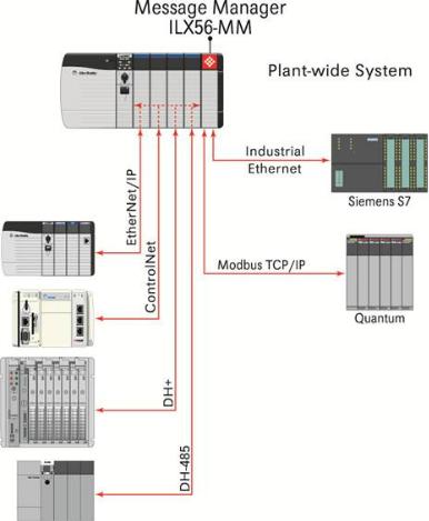
1.1Overview
The ILX56-Message Manager is a communications interface that can be installed in a Rockwell Automation® ControlLogix® 1756 chassis to provide data transfer functionality between automation systems based on a diverse range of controllers and processors. Supported systems include:
Rockwell Automation (RA) ControlLogix Programmable Automation Controller (PAC) systems
RA CompactLogix™ (CPLX) PAC systems
Allen-Bradley® (A-B) PLC5® systems
A-B SLC™ systems
A-B MicroLogix™ systems
Siemens Step 7® systems with Industrial Ethernet communications (does not support configured TSAP connections)
Schneider Electric® Quantum™ PLC systems with Modbus TCP/IP communications
Any devices that support Modbus TCP/IP Protocol
Page 12 of 112 |
ProSoft Technology, Inc. |
|
February 6, 2012 |

ILX56-MM ♦ ControlLogix Platform |
Start Here |
InRAx Message Manager for Industrial Communication |
User Manual |
|
|
1.2Deployment Checklist
Before you begin configuring the module, consider the following questions. Your answers will help you determine the scope of your project and the configuration requirements for a successful deployment.
1 ____________ Will the ILX56-MM require a static IP address for either or both Ethernet ports, or will it obtain IP address(es) from a DHCP Server? Obtain IP address information from your Network Administrator, and then record the IP Address settings in the following table:
Ethernet Ports |
Port 1 |
Port 2 |
DHCP? (Yes/No)
Static IP Address
Subnet Mask
Default Gateway
2____________ How many controllers and processors will be exchanging data
in your application?
3____________ What kinds of processors need to be linked for your application?
4 |
____________ What network protocols are used for the links? |
5 |
____________ What types of user accounts do you need to create? Users |
|
(to modify configurations) or Administrators (to control configuration access) |
6 |
____________ Which data transfers should happen on a regular timed- |
|
interval basis? Which transfers should happen only on data change or logic |
|
events? |
7____________ Do you need controllers or other communications modules installed in the same chassis as the ILX56-MM?
ProSoft Technology, Inc. |
Page 13 of 112 |
February 6, 2012 |
|

Start Here |
ILX56-MM ♦ ControlLogix Platform |
User Manual |
InRAx Message Manager for Industrial Communication |
|
|
1.3System Requirements
The ILX56-MM module requires the following minimum hardware and software components:
Rockwell Automation® ControlLogix™ processor, with compatible power supply and one free slot in the rack for the ILX56-MM module. The module requires 1 Amp of available 5 VDC power
Rockwell Automation RSLogix 5000 programming software version 16 or higher
Rockwell Automation RSLinx communication software version 2.51 or higher
Pentium® II 450 MHz minimum. Pentium III 733 MHz (or higher) recommended
Supported operating systems:
o Microsoft Windows Vista
o Microsoft Windows XP Professional with Service Pack 1 or 2
o Microsoft Windows 2000 Professional with Service Pack 1, 2, or 3 o Microsoft Windows Server 2003
Microsoft Internet Explorer version 7, or higher. Other web browsers are not
supported at this time
128 Mbytes of RAM minimum, 256 Mbytes of RAM recommended
100 Mbytes of free hard disk space (or more based on application requirements)
256-color VGA graphics adapter, 800 x 600 minimum resolution (True Color 1024 × 768 recommended)
CD-ROM drive
Note: The Hardware and Operating System requirements in this list are the minimum recommended to install and run software provided by ProSoft Technology. Other third party applications may have different minimum requirements. Refer to the documentation for any third party applications for system requirements.
|
|
|
|
|
|
|
|
Page 14 of 112 |
ProSoft Technology, Inc. |
||
|
|
February 6, 2012 |
|

ILX56-MM ♦ ControlLogix Platform |
Start Here |
InRAx Message Manager for Industrial Communication |
User Manual |
|
|
1.4Package Contents
The following components are included with your ILX56-MM module, and are all required for installation and configuration.
Important: Before beginning the installation, please verify that all of the following items are present.
|
|
|
|
|
|
|
Qty. |
Part Name |
Part Number |
Part Description |
|
|
|
|
|
|
|
1 |
ILX56-MM Module |
ILX56-MM |
InRAx Message Manager for Industrial |
||
|
|
|
|
Communication |
|
|
|
|
|
|
|
1 |
ProSoft Solutions CD |
CD-014 |
Contains sample programs, utilities, and |
||
|
|
|
|
documentation for the ILX56-MM module. |
|
|
|
|
|
|
|
1 |
Cable |
RL-CBL025 |
5 foot Ethernet Straight-Through Cable |
||
|
|
|
|
(Gray) |
|
If any of these components are missing, please contact ProSoft Technology Support for replacement parts.
ProSoft Technology, Inc. |
Page 15 of 112 |
February 6, 2012 |
|

Start Here |
ILX56-MM ♦ ControlLogix Platform |
User Manual |
InRAx Message Manager for Industrial Communication |
|
|
1.5Setup Jumper
There is one SETUP JUMPER located on the back of the module, labeled J1. The Setup Jumper acts as "write protection" for the module's firmware. In "write protected" mode, the Setup pins are not connected, and the module's firmware cannot be overwritten.
The following illustration shows the ILX56-MM jumper configuration, with the Setup Jumper OFF.
If you need to update the firmware, apply the Setup jumper to both pins.
Note: If you are installing the module in a remote rack, you may prefer to leave the Setup pins jumpered. That way, you can update the module's firmware without requiring physical access to the module.
|
|
|
|
|
|
|
|
Page 16 of 112 |
ProSoft Technology, Inc. |
||
|
|
February 6, 2012 |
|
ILX56-MM ♦ ControlLogix Platform |
Start Here |
InRAx Message Manager for Industrial Communication |
User Manual |
|
|
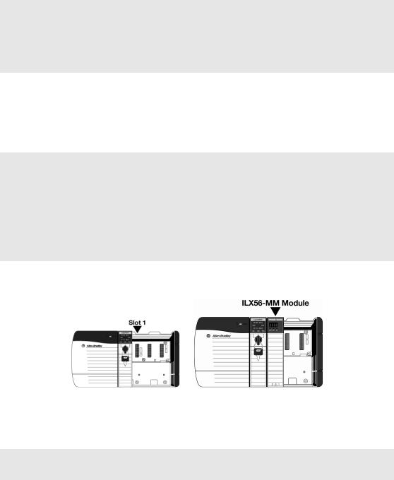
1.6Install the Module in the Rack
If you have not already installed and configured your ControlLogix processor and power supply, please do so before installing the ILX56-MM module. Refer to your Rockwell Automation product documentation for installation instructions.
Warning: You must follow all safety instructions when installing this or any other electronic devices. Failure to follow safety procedures could result in damage to hardware or data, or even serious injury or death to personnel. Refer to the documentation for each device you plan to connect to verify that suitable safety procedures are in place before installing or servicing the device.
After you have checked the placement of the jumper, insert ILX56-MM into the ControlLogix chassis. Use the same technique recommended by Rockwell Automation to remove and install ControlLogix modules.
You can install or remove ControlLogix system components while chassis power is applied and the system is operating. However, please note the following warning.
Warning: When you insert or remove the module while backplane power is on, an electrical arc can occur. An electrical arc can cause personal injury or property damage by:
sending an erroneous signal to your system's actuators causing unintended machine motion or loss of process control
causing an explosion in a hazardous environment
Verify that power is removed or the area is non-hazardous before proceeding. Repeated electrical arcing causes excessive wear to contacts on both the module and its mating connector. Worn contacts may create electrical resistance that can affect module operation.
1Align the module with the top and bottom guides, and then slide it into the rack until the module is firmly against the backplane connector.
2With a firm but steady push, snap the module into place.
3Check that the holding clips on the top and bottom of the module are securely in the locking holes of the rack.
4Turn power ON.
Note: If you insert the module improperly, the system may stop working, or may behave
unpredictably.
|
|
|
|
|
|
|
|
ProSoft Technology, Inc. |
Page 17 of 112 |
||
February 6, 2012 |
|
|
|

Start Here |
ILX56-MM ♦ ControlLogix Platform |
User Manual |
InRAx Message Manager for Industrial Communication |
|
|
1.7Connect to the Module's Web page
If your network is configured to use IP addresses in the range 192.168.1.xxx, open Microsoft Internet Explorer (version 7, or higher), and connect to the following address:
http://192.168.1.254
If your network is configured to use a different IP range, follow these steps:
1 Disconnect your PC from the network
2 Connect the Ethernet cable between the Ethernet port on your PC and Port 1 on the module
3Temporarily change the IP address and Subnet Mask on your PC to match the network configuration on the module:
IP address: 192.168.1.1 Subnet mask: 255.255.255.0
Important: Make a note of your IP Address settings. You will need to restore these settings before you reconnect to the network.
4Open Microsoft Internet Explorer (version 7, or higher) and connect to the following address:
http://192.168.1.254
5Click the LOGIN button at the bottom of the screen, and use the following username and password to login.
Username: admin
Password: admin
6Click the ADMINISTRATION tab, and then the NETWORK tab. Configure the IP
Address, Subnet Mask, and Default Gateway to work with your network.
7Click the SAVE button to apply the updated settings.
8Change the IP Address and Subnet Mask settings on your PC back to their original values, and then reconnect your PC to the network.
Page 18 of 112 |
ProSoft Technology, Inc. |
|
February 6, 2012 |

ILX56-MM ♦ ControlLogix Platform |
Start Here |
InRAx Message Manager for Industrial Communication |
User Manual |
|
|
9Connect to the module's web page again at the module's new IP address.
The following table describes the default Ethernet port configuration and login information.
Factory Default settings
|
Ethernet Ports: |
Port 1 |
Port 2 |
|
|
|
|
|
|
|
IP: |
192.168.1.254. |
DHCP |
|
|
|
|
|
|
|
User Name: |
admin |
|
|
|
|
|
|
|
|
Password: |
admin |
|
|
|
|
|
|
|
|
|
|
|
|
Important: The User Name and Password are case-sensitive.
|
|
|
|
|
|
|
|
ProSoft Technology, Inc. |
Page 19 of 112 |
||
February 6, 2012 |
|
|
|
Start Here |
ILX56-MM ♦ ControlLogix Platform |
User Manual |
InRAx Message Manager for Industrial Communication |
|
|
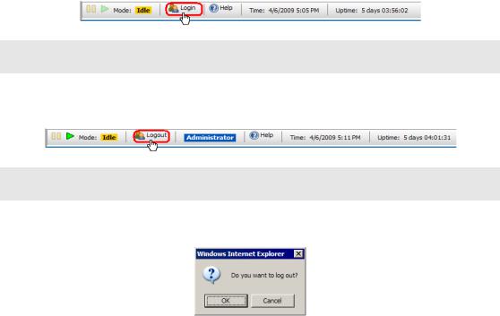
1.8Logging In
You can view the status and configuration of the ILX56-MM module without logging in. However, to modify the module's configuration, or to perform maintenance tasks, you must log in.
The LOGIN and LOGOUT buttons are located in the status bar at the bottom of the module's web page.
To Log In
Click the  LOGIN button on the status bar at the bottom of the page.
Note: Only one user can be logged into the module at a time.
To Log Out
Click the  LOGOUT button on the status bar at the bottom of the page.
Note: When you close the browser, you are automatically logged out of the module.
If you attempt to log out of the module without saving changes that you have made, you are prompted to save or cancel the changes.
Click OK to save the changes. Click CANCEL to discard the changes without saving.
Page 20 of 112 |
ProSoft Technology, Inc. |
|
February 6, 2012 |
ILX56-MM ♦ ControlLogix Platform |
Administration |
InRAx Message Manager for Industrial Communication |
User Manual |
|
|
2Administration
In This Chapter |
|
|
|
Device Information ................................................................................ |
22 |
|
Network Settings ................................................................................... |
23 |
|
System Functions.................................................................................. |
25 |
|
Time Sync ............................................................................................. |
27 |
|
Audit Log ............................................................................................... |
29 |
|
User Administration ............................................................................... |
30 |
|
Scanner Modes ..................................................................................... |
35 |
The ADMINISTRATION page allows you to view or modify administration functions. The following table describes the tabs on the Administration page.
|
Tab |
Function |
|
|
|
|
|
|
Device |
Configure device information. |
|
|
|
|
|
|
Network |
Configure the network ports. |
|
|
|
|
|
|
System |
Execute system functions. |
|
|
|
|
|
|
Time Sync |
Configure the time on the module |
|
|
|
Configure time synchronization for the controllers. |
|
|
|
|
|
|
Audit Log |
View the audit log. The audit log consists of system operational events that |
|
|
|
have occurred since the module was first started. For example, whenever |
|
|
|
the system mode is changed from run to idle or idle to run, this event will be |
|
|
|
in the log. |
|
|
|
|
|
|
Users |
Create and manage user accounts. |
|
|
|
You must be logged in with Administrator privilege to view this tab. |
|
|
|
|
|
|
|
|
|
Note: You must be logged on as a user with Administrator privilege to modify the settings on this page.
See also Security (page 31).
ProSoft Technology, Inc. |
Page 21 of 112 |
February 6, 2012 |
|

Administration |
ILX56-MM ♦ ControlLogix Platform |
User Manual |
InRAx Message Manager for Industrial Communication |
|
|
2.1Device Information
To open the DEVICE INFORMATION page, click the ADMINISTRATION tab, and then click the DEVICE tab.
The following table describes the fields on the DEVICE INFORMATION tab. The values you enter here are displayed on the Device Status page (page 70).
Field |
Description |
|
|
Name |
Name of the module. |
|
|
Description |
Description of the module. |
|
|
Location |
Location of the module. |
|
|
Contact |
The person responsible for the module. |
Click the SAVE button to save your changes.
Note: You must be logged on as a user with Administrator privilege to modify the settings on this
page.
See also Administration (page 21).
Page 22 of 112 |
ProSoft Technology, Inc. |
|
February 6, 2012 |

ILX56-MM ♦ ControlLogix Platform |
Administration |
InRAx Message Manager for Industrial Communication |
User Manual |
|
|
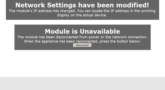
2.2Network Settings
To open the NETWORK SETTINGS page, click the ADMINISTRATION tab, and then click the NETWORK tab.
The module has two RJ45 Ethernet ports, located at the bottom of the front panel on the module. You can configure the following settings for each port.
Disabled
Static IP Address
o Subnet Mask
o Default Gateway (optional)
DHCP (auto-configured through a DHCP server)
Click the SAVE button to update these settings on the module.
Note: The only way to use both ports on the same subnet or Ethernet is to use a redundant wire
solution. Without this each port must be on a separate Ethernet network.
|
|
|
|
|
|
|
|
ProSoft Technology, Inc. |
Page 23 of 112 |
||
February 6, 2012 |
|
|
|
Administration |
ILX56-MM ♦ ControlLogix Platform |
User Manual |
InRAx Message Manager for Industrial Communication |
|
|
When you save the network settings, the module will log you out.
Click the RECONNECT button, or press [F5] to reconnect to the module.
If you lose connection with the module, you can put the module in Setup Mode to temporarily set the network port settings back to the default values (page 16). This will allow you to connect to the module and correct the network settings.
Note: You must be logged on as a user with Administrator privilege to modify the settings on this
page.
|
|
|
|
|
|
|
|
Page 24 of 112 |
ProSoft Technology, Inc. |
||
|
|
February 6, 2012 |
|

ILX56-MM ♦ ControlLogix Platform |
Administration |
InRAx Message Manager for Industrial Communication |
User Manual |
|
|
2.3System Functions
To open the SYSTEM FUNCTIONS page, click the ADMINISTRATION tab, and then click the SYSTEM tab.
ProSoft Technology, Inc. |
Page 25 of 112 |
February 6, 2012 |
|

Administration |
ILX56-MM ♦ ControlLogix Platform |
||||
User Manual |
InRAx Message Manager for Industrial Communication |
||||
|
|
|
|
|
|
|
|
System functions you can execute on the module include |
|||
|
|
|
|
|
|
|
|
Function |
Description |
||
|
|
|
|
|
|
|
|
Backup |
Choose which settings from the module you would like to backup by |
||
|
|
|
checking CONFIGURATION and/or ADMINISTRATIVE SETTINGS. Then click the |
||
|
|
|
BACKUP button to backup the current module configuration(s) to a file on |
||
|
|
|
your computer. |
||
|
|
|
ADMINISTRATIVE SETTINGS backs up all module configuration settings, |
||
|
|
|
including network settings, device name, and so on. |
||
|
|
|
CONFIGURATION backs up the only the information that pertains to the |
||
|
|
|
transfer of data. You can then use this backup file to configure another |
||
|
|
|
module with the same settings. |
||
|
|
|
|
|
|
|
|
Restore |
Click the BROWSE button to select a previously saved configuration file |
||
|
|
|
from your computer. |
||
|
|
|
Click the RESTORE button to restore the module to the state saved in the |
||
|
|
|
configuration file. |
||
|
|
|
The module is rebooted after the configuration is restored. You will be |
||
|
|
|
prompted to confirm the configuration restore and reboot. |
||
|
|
|
|
|
|
|
|
Set Log Level |
Set the log level at which the scanner module will record events. |
||
|
|
|
Level 1 logs errors only. This is the recommended setting for most |
||
|
|
|
applications. |
||
|
|
|
Levels 2 through 4 log informational events in increasing detail. Use |
||
|
|
|
these levels for troubleshooting and support. |
||
|
|
|
Level 0 logs only internal system errors. |
||
|
|
|
The scanner must be restarted before the new log level will take effect. |
||
|
|
|
Click the REINITIALIZE button to restart the scanner. You will be prompted |
||
|
|
|
to confirm the reinitialize. |
||
|
|
|
|
|
|
|
|
Clear Event Logs |
Clears the entire Event Log from the module. This cannot be undone. |
||
|
|
|
|
|
|
|
|
Update |
You can update the module's firmware from this page. You should only |
||
|
|
|
update the firmware if you have been directed to do so by ProSoft |
||
|
|
|
Technical Support. |
||
|
|
|
Click the BROWSE button to select the firmware file on your computer. |
||
|
|
|
Firmware files have the file extension "fwa". |
||
|
|
|
Click the UPDATE button to perform the update on the module. You will be |
||
|
|
|
prompted to confirm the update. |
||
|
|
|
IMPORTANT: Do not cycle power or disconnect the |
||
|
|
|
Ethernet cable until the update is complete. |
||
|
|
|
Important: You must clear your browser's cache (Tools/Delete Browsing |
||
|
|
|
History/Temporary Internet Files) after rebooting the module to ensure |
||
|
|
|
the old pages have been cleared from your browser's memory. |
||
|
|
|
|
|
|
|
|
Reboot |
Click the REBOOT button to reboot the module. You will be prompted to |
||
|
|
|
confirm the reboot. |
||
|
|
|
|
|
|
|
|
|
|
|
|
Note: You must be logged on as a user with Administrator privilege to modify the settings on this
page.
|
|
|
|
|
|
|
|
Page 26 of 112 |
ProSoft Technology, Inc. |
||
|
|
February 6, 2012 |
|
ILX56-MM ♦ ControlLogix Platform |
Administration |
InRAx Message Manager for Industrial Communication |
User Manual |
|
|
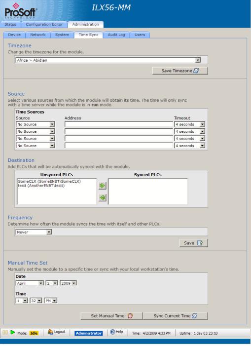
2.4Time Sync
To open the TIME SYNC page, click the ADMINISTRATION tab, and then click the
TIME SYNC tab.
ProSoft Technology, Inc. |
Page 27 of 112 |
February 6, 2012 |
|

Administration |
ILX56-MM ♦ ControlLogix Platform |
User Manual |
InRAx Message Manager for Industrial Communication |
|
|
The ILX56-MM module can acquire a time signal from an SNTP time server on the Internet, or from the ControlLogix processor in the same rack with the ILX56MM.
The ILX56-MM can also set the time on ControlLogix, CompactLogix, and FlexLogix processors defined as Devices.
Note: The module will only obtain, and push, time while in RUN mode.
|
|
|
|
|
Field |
Description |
|
|
|
|
|
|
Timezone |
Select the time zone for the module. |
|
|
|
|
|
|
Source |
The module can poll one or more sources for a time signal. |
|
|
|
TIME SOURCES specify the IP addresses for the time synchronization. The |
|
|
|
module will attempt to synchronize with each of these sources in the |
|
|
|
specified order until it is successful. |
|
|
|
TIMEOUT is the number of seconds the module will wait to receive the time |
|
|
|
signal from each source. |
|
|
|
|
|
|
Destination |
Select other devices that will be synchronized to the time on the module. |
|
|
|
The items on this list are derived from the devices you have defined in |
|
|
|
the Configuration Editor. |
|
|
|
|
|
|
Frequency |
Specify how often the module will receive and send time synchronization. |
|
|
|
A Time Sync cycle will be started when the module is switched to Run. |
|
|
|
Click the SAVE button to save your Time settings to the module. |
|
|
|
|
|
|
Manual Time Set |
Set the time and date, and then click the SET MANUAL TIME button. |
|
|
|
To synchronize the time and date on the module to the time and date on |
|
|
|
your local computer, click the SYNC CURRENT TIME button. |
|
|
|
|
|
|
|
|
|
Note: You must be logged on as a user with Administrator privilege to modify the settings on this
page.
|
|
|
|
|
|
|
|
Page 28 of 112 |
ProSoft Technology, Inc. |
||
|
|
February 6, 2012 |
|

ILX56-MM ♦ ControlLogix Platform |
Administration |
InRAx Message Manager for Industrial Communication |
User Manual |
|
|
2.5Audit Log
To open the AUDIT LOG page, click the ADMINISTRATION tab, and then click the
AUDIT LOG tab.
The audit log is a chronological log of operational system events that have occurred since the module was first started. The audit log displays 50 records per page, in order from newest, at the top, to oldest, at the bottom.
The Audit Log records the following types of events
Changing the module's operational mode
Modifying the configuration
Changing the event log level
Reinitializing the module
Backing up the configuration
Restoring the configuration
Updating the module
Other less frequent system events
Operation |
Description |
|
|
Next 50 |
Click the NEXT 50 button to view the 50 events that occurred prior to the |
|
current 50 events begin displayed. |
|
|
Previous 50 |
Click the PREVIOUS 50 button to view the 50 events that occurred after |
|
the current 50 events begin displayed. |
See also Security (page 31), Setup Mode (page 69), Administration (page 21).
ProSoft Technology, Inc. |
Page 29 of 112 |
February 6, 2012 |
|

Administration |
ILX56-MM ♦ ControlLogix Platform |
User Manual |
InRAx Message Manager for Industrial Communication |
|
|
2.6User Administration
To open the USER ADMINISTRATION page, click the ADMINISTRATION tab, then click the USERS tab.
Note: You must be logged on as a user with Administrator privilege to modify the settings on this
page.
|
|
|
|
|
|
|
|
Page 30 of 112 |
ProSoft Technology, Inc. |
||
|
|
February 6, 2012 |
|
 Loading...