


ILX69-PBM
CompactLogix or MicroLogix Platform
PROFIBUS Master Communication
Module
February 4, 2015
USER MANUAL
Your Feedback Please
We always want you to feel that you made the right decision to use our products. If you have suggestions, comments, compliments or complaints about our products, documentation, or support, please write or call us.
ProSoft Technology
5201 Truxtun Ave., 3rd Floor Bakersfield, CA 93309
+1 (661) 716-5100
+1 (661) 716-5101 (Fax) www.prosoft-technology.com support@prosoft-technology.com
© 2015 ProSoft Technology, Inc. All rights reserved.
ILX69-PBM User Manual
February 4, 2015
ProSoft Technology®, is a registered copyright of ProSoft Technology, Inc. All other brand or product names are or may be trademarks of, and are used to identify products and services of, their respective owners.
ProSoft Technology® Product Documentation
In an effort to conserve paper, ProSoft Technology no longer includes printed manuals with our product shipments. User Manuals, Datasheets, Sample Ladder Files, and Configuration Files are provided on the enclosed DVD and are available at no charge from our web site: http://www.prosoft-technology.com
Important Safety Information
THIS EQUIPMENT IS AN OPEN-TYPE DEVICE AND IS MEANT TO BE INSTALLED IN AN ENCLOSURE SUITABLE FOR THE ENVIRONMENT SUCH THAT THE EQUIPMENT IS ONLY ACCESSIBLE WITH THE USE OF A TOOL.
SUITABLE FOR USE IN CLASS I, DIVISION 2, GROUPS A, B, C AND D HAZARDOUS LOCATIONS, OR NONHAZARDOUS LOCATIONS ONLY.
WARNING - EXPLOSION HAZARD - DO NOT DISCONNECT EQUIPMENT WHILE THE CIRCUIT IS LIVE OR UNLESS THE AREA IS KNOWN TO BE FREE OF IGNITABLE CONCENTRATIONS.
WARNING - EXPLOSION HAZARD - SUBSTITUTION OF COMPONENT MAY IMPAIR SUITABILITY FOR CLASS I, DIVISION 2.
DEVICES SHALL BE USED WITH ALLEN BRADLEY 1769 BACKPLANES
INPUT TO THE DEVICES SHALL BE FUSED AT 5A MAXIMUM.
ILX69-PBM ♦ CompactLogix or MicroLogix Platform |
Contents |
PROFIBUS Master Communication Module |
User Manual |
|
|
Contents
Your Feedback Please........................................................................................................................ |
2 |
ProSoft Technology® Product Documentation .................................................................................... |
2 |
Important Safety Information............................................................................................................... |
2 |
1 |
Introduction |
7 |
||
|
|
|
|
|
|
1.1 |
About the User Manual.............................................................................................. |
7 |
|
|
1.1.1 |
Intended Audience .................................................................................................... |
7 |
|
|
1.2 |
General Information................................................................................................... |
7 |
|
|
1.3 |
Reference Systems ................................................................................................... |
8 |
|
|
1.4 |
1769 Programmable Controller Functionality............................................................ |
9 |
|
|
1.5 |
Requirements ............................................................................................................ |
9 |
|
|
1.5.1 |
Software Requirements............................................................................................. |
9 |
|
|
1.5.2 |
System Requirements ............................................................................................. |
10 |
|
|
1.5.3 |
Hardware Requirements ......................................................................................... |
10 |
|
2 |
Safety |
|
11 |
|
|
|
|
|
|
|
2.1 |
General Note ........................................................................................................... |
11 |
|
|
2.2 |
Personnel Qualification ........................................................................................... |
11 |
|
|
2.3 |
Safety Instructions to Avoid Personal Injury............................................................ |
11 |
|
|
2.3.1 |
Electrical Shock Hazard .......................................................................................... |
12 |
|
|
2.3.2 |
Communication Stop During Firmware Update ...................................................... |
12 |
|
|
2.4 |
Safety Instructions to Avoid Property Damage ....................................................... |
12 |
|
|
2.4.1 |
Device Destruction if ILX69-PBM is Installed to Powered PLC .............................. |
13 |
|
|
2.4.2 |
Device Destruction by Exceeding Allowed Supply Voltage .................................... |
13 |
|
|
2.4.3 |
Device Destruction by Exceeding Allowed Signaling Voltage................................. |
13 |
|
|
2.4.4 |
Electrostatically sensitive devices ........................................................................... |
13 |
|
|
2.5 |
Labeling of Safety Messages .................................................................................. |
14 |
|
|
2.6 |
Safety References................................................................................................... |
15 |
|
3 |
About the ILX69-PBM |
17 |
||
|
|
|
|
|
|
3.1 |
Device Drawing ....................................................................................................... |
17 |
|
|
3.2 |
PROFIBUS Interface ............................................................................................... |
18 |
|
|
3.2.1 |
Wiring Instructions ................................................................................................... |
18 |
|
|
3.3 |
Ethernet Interface.................................................................................................... |
20 |
|
|
3.3.1 |
Ethernet Pin Assignment at the RJ45 Socket ......................................................... |
20 |
|
|
3.3.2 |
Ethernet Connection Data ....................................................................................... |
20 |
|
|
3.4 |
Removable Memory Card ....................................................................................... |
21 |
|
|
3.5 |
Power Supply .......................................................................................................... |
21 |
|
|
4 |
Installation |
23 |
||
|
|
|
|
|
|
|
|
4.1 |
System Planning Considerations ............................................................................ |
23 |
|
|
|
4.2 |
Software Installation ................................................................................................ |
24 |
|
|
|
4.2.1 |
Installing ProSoft fdt Configuration Manager in Windows 7.................................... |
24 |
|
|
|
4.3 |
ILX69-PBM Hardware Installation ........................................................................... |
26 |
|
|
|
|
|
|
|
ProSoft Technology, Inc. |
|
Page 3 of 124 |
|||
February 4, 2015 |
|
|
|
||
Contents |
|
ILX69-PBM ♦ CompactLogix or MicroLogix Platform |
||||
User Manual |
|
PROFIBUS Master Communication Module |
||||
|
|
|
|
|
|
|
|
|
4.3.1 |
Safety Precautions.................................................................................................. |
|
26 |
|
|
|
4.3.2 |
Installing the ILX69-PBM Module ........................................................................... |
|
27 |
|
4.4 |
|
Uninstalling ILX69-PBM Hardware ......................................................................... |
|
27 |
||
|
5 |
Configuration and Start-Up |
|
29 |
||
|
|
|
|
|
|
|
|
5.1 |
|
CompactLogix Project............................................................................................. |
|
29 |
|
|
|
5.1.1 |
Creating a New Project ........................................................................................... |
|
29 |
|
|
|
5.1.2 |
Module Properties 1................................................................................................ |
|
32 |
|
|
|
5.1.3 |
Module Properties 2................................................................................................ |
|
33 |
|
|
|
5.1.4 |
Importing the Ladder Rung ..................................................................................... |
|
34 |
|
5.2 |
|
ProSoft fdt Configuration Manager ......................................................................... |
|
37 |
||
|
|
5.2.1 |
Creating a New ILX69-PBM Project ....................................................................... |
|
37 |
|
|
|
5.2.2 |
PROFIBUS Master Configuration ........................................................................... |
|
39 |
|
|
|
5.2.3 |
PROFIBUS Slave Configuration ............................................................................. |
|
40 |
|
5.3 |
|
Downloading the Project to the ILX69-PBM ........................................................... |
|
45 |
||
|
|
5.3.1 |
Assigning an IP Address......................................................................................... |
|
45 |
|
|
|
5.3.2 |
Downloading the Project......................................................................................... |
|
47 |
|
5.4 |
|
Adjusting Input/Output Data Lengths in the Project ............................................... |
|
51 |
||
|
|
5.4.1 |
Determining the Number of PROFIBUS Inputs/Outputs Used |
............................... 51 |
||
|
|
5.4.2 |
Studio 5000 Adjustment (Optional)......................................................................... |
|
53 |
|
5.5 |
|
Project Storage ....................................................................................................... |
|
56 |
||
|
|
5.5.1 |
Store Function......................................................................................................... |
|
57 |
|
|
|
5.5.2 |
Restore Function .................................................................................................... |
|
57 |
|
|
|
5.5.3 |
Project File Backup and SD Card Handling............................................................ |
|
58 |
|
|
|
5.5.4 |
Start-up Behavior with or without SD Card ............................................................. |
|
60 |
|
|
|
5.5.5 |
STARTUP.INI File................................................................................................... |
|
61 |
|
|
|
5.5.6 |
Reset Device to Factory Settings with Memory Card ............................................. |
|
61 |
|
6 |
Communication |
|
63 |
|||
|
|
|
|
|
|
|
6.1 |
|
Studio 5000 PROFIBUS Data Values .................................................................... |
|
63 |
||
|
|
6.1.1 |
PROFIBUS Network Input Data.............................................................................. |
|
63 |
|
|
|
6.1.2 |
PROFIBUS Network Output Data........................................................................... |
|
63 |
|
6.2 |
|
I/O Communication and Memory Map .................................................................... |
|
64 |
||
|
|
6.2.1 |
I/O Arrays Overview................................................................................................ |
|
64 |
|
|
|
6.2.2 |
Input Array .............................................................................................................. |
|
65 |
|
|
|
6.2.3 |
Output Array............................................................................................................ |
|
77 |
|
6.3 |
|
Acyclic Messaging .................................................................................................. |
|
82 |
||
|
|
6.3.1 |
Supported PROFIBUS DP Messages .................................................................... |
|
82 |
|
|
|
6.3.2 |
Standard Messaging ............................................................................................... |
|
82 |
|
|
|
6.3.3 |
DPV1 Messaging .................................................................................................... |
|
85 |
|
|
|
6.3.4 |
CIP Message Error Codes ...................................................................................... |
|
88 |
|
7 |
Diagnostics and Troubleshooting |
|
93 |
|||
|
|
|
|
|
|
|
7.1 |
|
Web Page ............................................................................................................... |
|
93 |
||
|
|
7.1.1 |
General Device and Diagnosis Information ............................................................ |
|
94 |
|
|
|
7.1.2 |
Firmware Update .................................................................................................. |
|
100 |
|
7.2 |
|
Hardware LEDs..................................................................................................... |
|
106 |
||
|
|
7.2.1 |
CompactLogix LEDs ............................................................................................. |
|
106 |
|
|
|
7.2.2 |
ILX69-PBM LEDs.................................................................................................. |
|
107 |
|
7.3 |
|
Troubleshooting .................................................................................................... |
|
110 |
||
|
|
|
|
|
||
Page 4 of 124 |
|
ProSoft Technology, Inc. |
||||
|
|
|
|
|
February 4, 2015 |
|

ILX69-PBM ♦ CompactLogix or MicroLogix Platform |
Contents |
||||
PROFIBUS Master Communication Module |
User Manual |
||||
|
|
|
|
|
|
|
8 |
Technical Data |
111 |
||
|
|
|
|
|
|
|
|
8.1 |
Technical Data - ILX69-PBM................................................................................. |
111 |
|
|
|
8.2 |
Technical Data - PROFIBUS................................................................................. |
113 |
|
9 |
Annex |
|
115 |
||
|
|
|
|
|
|
|
|
9.1 |
PROFIBUS Functionality....................................................................................... |
115 |
|
|
|
9.1.1 |
DPV0 Services ...................................................................................................... |
115 |
|
|
|
9.1.2 |
DPV1 Services ...................................................................................................... |
116 |
|
|
|
9.2 |
Disposal of Electronic Equipment Waste .............................................................. |
117 |
|
|
|
9.3 |
References ............................................................................................................ |
117 |
|
|
|
9.4 |
Glossary ................................................................................................................ |
118 |
|
|
10 Support, Service & Warranty |
121 |
|||
|
|
|
|
|
|
|
|
10.1 |
Contacting Technical Support ............................................................................... |
121 |
|
|
|
10.2 |
Warranty Information............................................................................................. |
122 |
|
|
Index |
|
123 |
||
|
|
|
|
|
|
ProSoft Technology, Inc. |
Page 5 of 124 |
February 4, 2015 |
|

Contents |
ILX69-PBM ♦ CompactLogix or MicroLogix Platform |
User Manual |
PROFIBUS Master Communication Module |
|
|
Page 6 of 124 |
ProSoft Technology, Inc. |
|
February 4, 2015 |

ILX69-PBM ♦ CompactLogix or MicroLogix Platform |
Contents |
||
PROFIBUS Master Communication Module |
User Manual |
||
1 |
Introduction |
|
|
|
In This Chapter |
|
|
|
About the User Manual ........................................................................... |
7 |
|
|
|
General Information ................................................................................ |
7 |
|
|
Reference Systems................................................................................. |
8 |
|
1769 Programmable Controller Functionality.......................................... |
9 |
|
|
|
Requirements ......................................................................................... |
9 |
1.1About the User Manual
This user manual provides descriptions and detailed information about:
How to assemble the ILX69-PBM into a CompactLogix™ system.
PROFIBUS wiring
Configuration and start-up
Communication
Diagnostics
LED displays
Technical data and electrical/environmental specifications
1.1.1 Intended Audience
The intended audiences for this manual are the individuals responsible for designing, installing, programming, or troubleshooting control systems that use the Rockwell
CompactLogix™ 1769 programmable controller and the ILX69-PBM. You should have a basic understanding of electrical circuitry and familiarity with relay logic. If you do not, obtain the proper training before using this product.
1.2General Information
The ILX69-PBM is a PROFIBUS DP master module for the CompactLogix™ platform which allows the PLC to control data exchange on a PROFIBUS network. The ILX69-PBM handles the cyclic data exchange between the connected PROFIBUS slaves.
The data exchange between the CompactLogix™ controller and the ILX69-PBM is done via the I/O process data image using CompactLogix™ backplane technology. The process image of the CompactLogix™ and of the ILX69-PBM is updated automatically during runtime.
ProSoft Technology, Inc. |
Page 7 of 124 |
February 4, 2015 |
|
Contents |
ILX69-PBM ♦ CompactLogix or MicroLogix Platform |
User Manual |
PROFIBUS Master Communication Module |
|
|
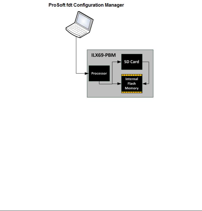
The configuration and diagnostics of the ILX69-PBM is done using the ProSoft fdt Configuration Manager software over an Ethernet connection. The configuration is stored permanently using the on-board FLASH memory of the ILX69-PBM and is available immediately on power up. ProSoft fdt Configuration Manager allows you to backup the configuration project files from the internal flash memory to an inserted SD memory card. Basic diagnostics of the ILX69-PBM can be done via its web page.
1.3Reference Systems
The firmware of the ILX69-PBM was developed and tested with the following CompactLogix™ controller types and firmware revisions.
CompactLogix System
Controller |
Firmware |
|
|
CompactLogix™ 1769-L23 |
V17.05 |
|
|
CompactLogix™ 1769-L32E |
V20.13 |
|
|
CompactLogix™ 1769-L36ERM |
V21.11 |
|
|
Page 8 of 124 |
ProSoft Technology, Inc. |
|
February 4, 2015 |

ILX69-PBM ♦ CompactLogix or MicroLogix Platform |
Contents |
PROFIBUS Master Communication Module |
User Manual |
|
|
1.41769 Programmable Controller Functionality
PROFIBUS DP supports acyclic services through messages. These PROFIBUS DP services are supported by the Studio 5000 programming tool using CIP messages. Not all of the 1769 programmable controllers support CIP messaging.
The basic PROFIBUS DP acyclic services Global Control or slave Diagnostics request are also executable in addition to the CIP method by using the I/O area. The following table displays the 1769 programmable controllers and the functionalities they support.
CompactLogix System
|
|
CIP |
Processor |
I/O (cyclic) |
Messaging |
|
|
(acyclic) |
|
|
|
CompactLogix™ 1769-L23 |
Yes |
Yes |
|
|
|
CompactLogix™ 1769-L30 |
Yes |
No |
|
|
|
CompactLogix™ 1769-L31 |
Yes |
Yes |
|
|
|
CompactLogix™ 1769-L32E |
Yes |
Yes |
|
|
|
CompactLogix™ 1769-L35E |
Yes |
Yes |
|
|
|
CompactLogix™ 1769-L36ERM |
Yes |
Yes |
|
|
|
Yes = Functionality supported
No = Functionality not supported
1.5Requirements
1.5.1 Software Requirements
The software requirements for using the ILX69-PBM within a CompactLogix™ system are listed below. You must have the following software installed on your PC unless otherwise noted:
CompactLogix System
Studio 5000 programming software, V21.00 or higher
RSLogix™ 5000 programming software, V20.00 or higher
ProSoft Configuration Software
ProSoft fdt Configuration Manager for Rockwell Interfaces V1.0.x.x or higher
ProSoft Technology, Inc. |
Page 9 of 124 |
February 4, 2015 |
|

Contents |
ILX69-PBM ♦ CompactLogix or MicroLogix Platform |
User Manual |
PROFIBUS Master Communication Module |
|
|
1.5.2 System Requirements
ProSoft fdt Configuration Manager software
PC with 1 GHz processor or higher
Windows® 7 (32 bit) SP1, Windows® 7 (64 bit) SP1, Windows® XP (32 bit) SP3
Administrator privilege required for installation
Internet Explorer 5.5 or higher
The software Microsoft .NET Framework 3.5 or 4.0 (Included in the ProSoft fdt Configuration Manager installation package)
Free disk space: minimum 400 MB
DVD ROM drive
RAM: minimum 512 MB, recommended 1024 MB
Graphic resolution: minimum 1024 x 768 pixel
Keyboard and Mouse
Note: If the solution file is saved and opened again, or if the solution file is used on another PC, the system requirements must match. Particularly, the DTM must be installed on the used PC.
Restrictions
Touch screen is not supported.
When ProSoft fdt Configuration Manager is installed on a PC, Hilscher standard SYCON.net and legacy PROSOFT.fdt cannot be and shall not be installed, and viceversa.
1.5.3 Hardware Requirements
The following minimum hardware is required to use the ILX69-PBM:
Windows PC for the ProSoft fdt Configuration Manager software (advantageous with SD card slot or SD card reader). Refer to section System Requirements (page 10).
Ethernet cable for ProSoft fdt Configuration Manager or ILX69-PBM web page connection.
CompactLogix System
Personal Computer
1769 – Programmable controller (1769-L23, 1769-L32E and 1769-L36ERM)
1769 – Power supply
1769 – Right or left termination end cap
Ethernet cable for interface to the 1769 programmable controller.
Page 10 of 124 |
ProSoft Technology, Inc. |
|
February 4, 2015 |
ILX69-PBM ♦ CompactLogix or MicroLogix Platform |
Contents |
PROFIBUS Master Communication Module |
User Manual |
|
|
2 |
Safety |
|
|
|
In This Chapter |
|
|
|
|
General Note ......................................................................................... |
11 |
|
|
Personnel Qualification .......................................................................... |
11 |
|
Safety Instructions to Avoid Personal Injury........................................... |
11 |
|
|
Safety Instructions to Avoid Property Damage ...................................... |
12 |
|
|
Labeling of Safety Messages................................................................. |
14 |
|
|
|
Safety References ................................................................................. |
15 |
2.1General Note
The documentation in the form of a user manual, an operating instruction manual or other manual types, as well as the accompanying texts have been created for the use of the products by educated personnel. When using the products, all Safety Messages, Integrated Safety Messages, Property Damage Messages and all valid legal regulations must be obeyed. Technical knowledge is presumed. The user must assure that all legal regulations are obeyed.
2.2Personnel Qualification
The ILX69-PBM must only be installed, configured, and removed by qualified personnel. Job-specific technical skills for people professionally working with electricity must be present concerning the following topics:
Safety and health at work
Mounting and connecting of electrical equipment
Measurement and analysis of electrical functions and systems
Evaluation of the safety of electrical systems and equipment
Installing and configuring IT systems
2.3Safety Instructions to Avoid Personal Injury
To ensure your own personal safety and to avoid personal injury, you necessarily must read, understand and follow the safety instructions and safety messages in this manual before you install and operate the ILX69-PBM.
ProSoft Technology, Inc. |
Page 11 of 124 |
February 4, 2015 |
|

Contents |
ILX69-PBM ♦ CompactLogix or MicroLogix Platform |
User Manual |
PROFIBUS Master Communication Module |
|
|
2.3.1 Electrical Shock Hazard
The danger of a lethal electrical shock caused by parts with more than 50V may occur if you power a PLC power supply module when its housing is open.
HAZARDOUS VOLTAGE is present inside of a powered PLC power supply module.
Strictly obey all safety rules provided by the device manufacturer in the documentation.
Disconnect the network power (power plug) from the power supply module before you disconnect the PLC module from the backplane.
When you disconnect the PLC module from the power supply module, use end cap terminators and close the power supply module housing.
An electrical shock is the result of a current flowing through the human body. The resulting effect depends on the intensity and duration of the current and on its path through the body. Currents in the range of approximately ½ mA can cause effects in persons with good health, and indirectly cause injuries resulting from startling responses. Higher currents can cause more direct effects, such as burns, muscle spasms, or ventricular fibrillation.
In dry conditions, permanent voltages up to approximately 42.4 V peak or 60 V are not considered as dangerous if the contact area is equivalent to the size of a human hand.
More information is located at Safety References (page 15).
2.3.2 Communication Stop During Firmware Update
If you plan a firmware update via the ProSoft web pages, please yield:
During the firmware update procedure, a device reset is performed and stops all module communication functions with network devices. An unintended plant stop can cause personal injury.
Initiating a device reset causes a device reboot. A reboot stops all communication immediately.
Personal injury by consequence of careless use caused plant stop can not be excluded.
All fieldbus devices should be placed in a fail-safe condition under direct supervision before starting a firmware update.
Before you initiate a reset, make sure your system is in an idle state and operating under maintenance conditions in order to prevent personal injury.
Stop the PLC program before you start the firmware update.
More firmware update information is located at Firmware Update (page 100).
2.4Safety Instructions to Avoid Property Damage
To avoid system damage and device destruction to the ILX69-PBM, you necessarily must read, understand and follow the following safety instructions and safety messages in this manual before you install and operate the ILX69-PBM.
Page 12 of 124 |
ProSoft Technology, Inc. |
|
February 4, 2015 |

ILX69-PBM ♦ CompactLogix or MicroLogix Platform |
Contents |
PROFIBUS Master Communication Module |
User Manual |
|
|
2.4.1 Device Destruction if ILX69-PBM is Installed to Powered PLC
To avoid device destruction when the ILX69-PBM is powered up:
Strictly obey to all safety rules provided by the PLC device manufacturer documentation. Shut off the power supply of the PLC, before you install the ILX69-PBM module.
2.4.2 Device Destruction by Exceeding Allowed Supply Voltage
To avoid device destruction due to high supply voltage to the ILX69-PBM, you must observe the following instructions.
The ILX69-PBM may only be operated with the specified supply voltage. Make sure that the limits of the allowed range for the supply voltage are not exceeded.
A supply voltage above the upper limit can cause severe damage to the ILX69-PBM.
A supply voltage below the lower limit can cause malfunction in the ILX69-PBM.
The allowed range for the supply voltage is defined by the tolerances specified in this manual.
Mandatory supply voltage information is located at Power Supply (page 21).
2.4.3 Device Destruction by Exceeding Allowed Signaling Voltage
To avoid device destruction due to high signal voltage to the ILX69-PBM, you must observe the following instructions.
All I/O signal pins at the ILX69-PBM tolerate only the specified signaling voltage.
Operation of the ILX69-PBM with a signaling voltage other than the specified signaling voltage may lead to severe damage to the module.
Mandatory signaling voltage information is located at Power Supply (page 21).
2.4.4 Electrostatically sensitive devices
This equipment is sensitive to electrostatic discharge, which can cause internal damage and affect normal operation. Therefore, adhere to the necessary safety precautions for components that are vulnerable with electrostatic discharge when handling the ILX69-PBM. Follow the guidelines listed when you handle this equipment:
Touch a grounded object to discharge potential static.
Wear an approved grounding wrist strap.
Do not touch connectors or pins on the ILX69-PBM.
Do not touch circuit components inside the equipment.
If available, use a static-safe workstation.
When not in use, store the equipment in appropriate static-safe packaging.
More information is located at Safety References (page 15).
ProSoft Technology, Inc. |
Page 13 of 124 |
February 4, 2015 |
|
Contents |
ILX69-PBM ♦ CompactLogix or MicroLogix Platform |
User Manual |
PROFIBUS Master Communication Module |
|
|
2.5Labeling of Safety Messages
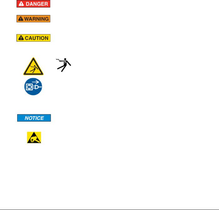
The Safety Messages at the beginning of a chapter are pinpointed particularly and highlighted by a signal word according to the degree of endangerment. The type of danger is specified by the safety message text and optionally by a specific safety sign.
The Integrated Safety Messages within an instruction description are highlighted with a signal word according to the degree of endangerment. The type of danger is specified by the safety message text.
|
Signal Word |
Meaning (International) |
Meaning (USA) |
|
|
|
|
|
|
|
|
|
|
Indicates a direct hazard with high risk, |
Indicates a hazardous situation which if not |
|
|
|
|
which will have a consequence of death or |
avoided, will result in death or serious injury. |
|
|
|
|
grievous bodily harm if it is not avoided. |
|
|
|
|
|
|
|
|
|
|
|
Indicates a possible hazard with medium |
Indicates a hazardous situation which if not |
|
|
|
|
risk, which will have a consequence of |
avoided, could result in death or serious |
|
|
|
|
death or (grievous) bodily harm if it is not |
injury. |
|
|
|
|
avoided. |
|
|
|
|
|
|
|
|
|
|
|
Indicates a minor hazard with medium risk, |
Indicates a hazardous situation which if not |
|
|
|
|
which could have a consequence of simple |
avoided, may result in minor or moderate |
|
|
|
|
battery if it is not avoided. |
Injury. |
|
|
|
|
|
|
|
|
|
Safety Sign |
USA |
Warning or Principle |
|
|
|
|
|
|
|
|
|
|
|
Warning of lethal electrical shock |
|
|
|
|
|
|
|
|
|
|
|
Principle: Disconnect the power plug |
|
|
|
|
|
|
|
|
|
|
|
|
|
|
|
Signal Word |
Meaning (International and USA) |
|
|
|
|
|
|
|
|
|
|
|
Indicates a property damage message. |
|
|
|
|
|
|
|
|
|
|
Safety Sign |
Warning or Principle |
|
|
|
|
|
|
|
||
|
|
Warning on damages by electrostatic discharge |
|
||
|
|
|
|
||
|
- |
Example: Warning of device destruction due to exceedingly high supply voltage |
|
||
|
|
|
|
|
|
In this document, all Safety Instructions and Safety Messages are designed according both to the international used safety conventions as well as to the ANSI Z535.6 standard, refer to Safety References (page 15).
In this document, the signal words ‘WARNING’, ‘CAUTION’ and ‘NOTICE’ are used according to ANSI Z535.6 standard. The meaning given in ISO/IEC 26514 [4] section ‘11.11
Contents of warnings and cautions is not relevant in this manual.
Page 14 of 124 |
ProSoft Technology, Inc. |
|
February 4, 2015 |

ILX69-PBM ♦ CompactLogix or MicroLogix Platform |
Contents |
PROFIBUS Master Communication Module |
User Manual |
|
|
2.6Safety References
[S1] |
ANSI Z535.6-2006 American National Standard for Product Safety Information in Product |
|
Manuals, Instructions, and Other Collateral Materials |
[S2] |
IEC 60950-1, Information technology equipment - Safety - Part 1: General requirements, (IEC |
|
60950-1:2005, modified); German Edition EN 60950-1:2006 |
[S3] |
EN 61340-5-1 and EN 61340-5-2 as well as IEC 61340-5-1 and IEC 61340-5-2 |
[S4] |
26514-2010 - IEEE Standard for Adoption of ISO/IEC 26514:2008 Systems and Software |
|
Engineering--Requirements for Designers and Developers of User Documentation |
ProSoft Technology, Inc. |
Page 15 of 124 |
February 4, 2015 |
|

Contents |
ILX69-PBM ♦ CompactLogix or MicroLogix Platform |
User Manual |
PROFIBUS Master Communication Module |
|
|
Page 16 of 124 |
ProSoft Technology, Inc. |
|
February 4, 2015 |

ILX69-PBM ♦ CompactLogix or MicroLogix Platform |
Contents |
||
PROFIBUS Master Communication Module |
User Manual |
||
3 |
About the ILX69-PBM |
|
|
|
In This Chapter |
|
|
|
|
Device Drawing...................................................................................... |
17 |
|
|
PROFIBUS Interface.............................................................................. |
18 |
|
|
Ethernet Interface .................................................................................. |
20 |
|
|
Removable Memory Card ...................................................................... |
21 |
|
|
Power Supply......................................................................................... |
21 |
3.1Device Drawing
ProSoft Technology, Inc. |
Page 17 of 124 |
February 4, 2015 |
|
Contents |
ILX69-PBM ♦ CompactLogix or MicroLogix Platform |
User Manual |
PROFIBUS Master Communication Module |
|
|
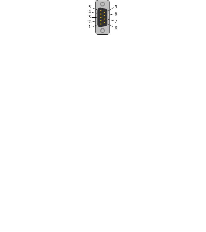
3.2PROFIBUS Interface
PROFIBUS Interface (D-Sub female connector, 9 pin):
Connection with D- |
Signal |
Description |
Sub female connector |
|
|
|
|
|
3 |
RxD / TxD-P |
Receive/Send Data-P, respectively connection B plug |
|
|
|
4 |
CNTR-P |
Repeater-Control |
|
|
|
5 |
DGND |
Data Ground |
|
|
|
6 |
VP |
Positive supply voltage |
|
|
|
8 |
RxD / TxD-N |
Receive/Send Data-N, respectively connection A plug |
|
|
|
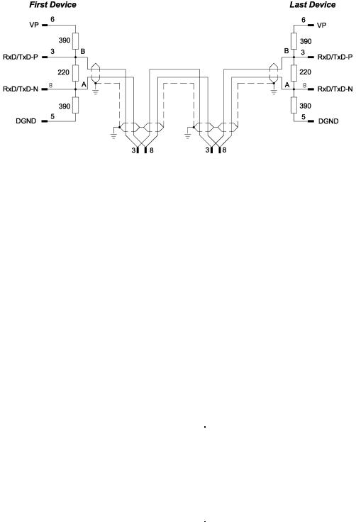
3.2.1 Wiring Instructions
Please ensure that termination resistors are available at both ends of the PROFIBUS network cable. If special PROFIBUS connectors are being used, these resistors are often found inside the connector and must be switched on at each end of the PROFIBUS network cable.
For baud rates above 1.5 MBaud, use only special connectors for higher baud rates. These include additional inductance.
It is not permitted to have T-stubs on PROFIBUS high baud rates. Use only a special cable which is approved for PROFIBUS DP. Make a solid connection from the cable shield to ground at every device and make sure that there is no potential difference between the grounds at the devices.
Page 18 of 124 |
ProSoft Technology, Inc. |
|
February 4, 2015 |
ILX69-PBM ♦ CompactLogix or MicroLogix Platform |
Contents |
PROFIBUS Master Communication Module |
User Manual |
|
|
If the ILX69-PBM is linked with only one other device on the bus, both devices must be connected to the ends of the bus line. These devices must deliver the supply voltage for the termination resistors. If three or more devices are connected to the bus, the ILX69-PBM can be connected at any desired position.
Up to 32 PROFIBUS devices can be connected to one bus segment, without repeaters. If several bus segments are linked to each other with repeaters, there can be up to 127 devices on the network.
The maximum permissible cable length of a PROFIBUS segment depends on the baud rate used, see the following table.
Baud rate in kBit/s |
Maximum distance |
|
|
|
|
9.6 |
1,200 meters |
3,940 feet |
|
|
|
19.2 |
1,200 m |
3,940 ft |
|
|
|
93.75 |
1,200 m |
3,940 ft |
|
|
|
187.5 |
1,000 m |
3,280 ft |
|
|
|
500 |
400 m |
1,310 ft |
|
|
|
1,500 |
200 m |
656 ft |
|
|
|
3,000 |
100 m |
328 ft |
|
|
|
6,000 |
100 m |
328 ft |
|
|
|
12,000 |
100 m |
328 ft |
|
|
|
Only PROFIBUS certified cables, preferably the cable type A, should be used. The following table contains important electrical data concerning PROFIBUS certified cable:
|
Parameter |
Value |
|
|
|
|
|
|
Impedance |
35 to 165 Ohm at frequencies from |
|
|
|
3 to 20 Mhz |
|
|
|
|
|
|
Capacity per units |
< 30 pF/m |
|
|
length |
|
|
|
|
|
|
|
Loop resistance |
110 Ohm/km |
|
|
|
|
|
|
Wire gauge |
0.64 mm |
|
|
|
|
|
ProSoft Technology, Inc. |
|
Page 19 of 124 |
|
February 4, 2015 |
|
|
|
Contents |
ILX69-PBM ♦ CompactLogix or MicroLogix Platform |
User Manual |
PROFIBUS Master Communication Module |
|
|
3.3Ethernet Interface
The Ethernet cable should contain an RJ45 connector. It should have a twisted pair cable of category 5 (CAT5) or higher, which consists of 4 twisted cores and has a maximum transmission rate of 100 MBit/s (CAT5).
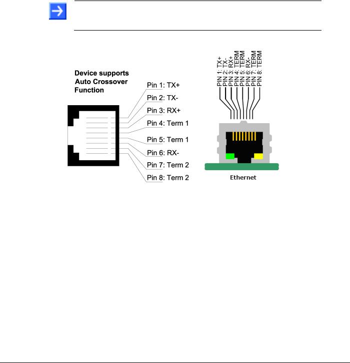
3.3.1 Ethernet Pin Assignment at the RJ45 Socket
Note: The device supports the Auto Crossover function. The RX and TX can be switched. The following figure shows the RJ45 standard pin assignment.
Pin |
|
Signal |
|
Description |
1 |
|
TX+ |
|
Transmit Data + |
|
|
|
|
|
2 |
|
TX– |
|
Transmit Data – |
|
|
|
|
|
3 |
|
RX+ |
|
Receive Data + |
|
|
|
|
|
4 |
|
Term 1 |
|
Connected to each other and |
|
|
|
|
terminated to PE through RC circuit* |
5 |
|
Term 1 |
|
|
|
|
|
||
|
|
|
|
|
6 |
|
RX– |
|
Receive Data – |
|
|
|
|
|
7 |
|
Term 2 |
|
Connected to each other and |
|
|
|
|
terminated to PE through RC circuit* |
8 |
|
Term 2 |
|
|
|
|
|
||
|
|
|
|
|
|
|
|
|
*Bob Smith Termination |
|
|
|
|
|
3.3.2 Ethernet Connection Data
Medium |
2 x 2 Twisted-pair copper cable, CAT5 (100 MBit/s) or better |
|
|
Length of cable |
Maximum 100 m |
|
|
Transmission rate |
10 MBit/s / 100 MBit/s |
|
|
Page 20 of 124 |
ProSoft Technology, Inc. |
|
February 4, 2015 |
ILX69-PBM ♦ CompactLogix or MicroLogix Platform |
Contents |
PROFIBUS Master Communication Module |
User Manual |
|
|
3.4 Removable Memory Card
Memory Card
Type |
SD card (HDSC format is not supported) |
|
|
Maximum storage capacity |
4 GByte |
|
|
Required formatting |
FAT16 format (no FAT32) |
|
|
SD Card Connector
SD Card Connector, e.g. FPS009-2405-0 push/push
3.5Power Supply
Power supply |
5V from backplane |
|
|
Current Load |
570 mA Max. @ 5 VDC |
CompactLogix |
Power rating of 2 |
|
|
|
|
Backplane power |
5 VDC: Min: 4.75 V at Module; Max: 5.40 V at Module |
|
24 VDC: Min: 19.9 V at Module; Max: 26.4 V at Module |
|
|
ProSoft Technology, Inc. |
Page 21 of 124 |
February 4, 2015 |
|

Contents |
ILX69-PBM ♦ CompactLogix or MicroLogix Platform |
User Manual |
PROFIBUS Master Communication Module |
|
|
Page 22 of 124 |
ProSoft Technology, Inc. |
|
February 4, 2015 |

ILX69-PBM ♦ CompactLogix or MicroLogix Platform |
Contents |
||
PROFIBUS Master Communication Module |
User Manual |
||
4 |
Installation |
|
|
|
In This Chapter |
|
|
|
|
System Planning Considerations ........................................................... |
23 |
|
|
Software Installation............................................................................... |
24 |
|
|
ILX69-PBM Hardware Installation .......................................................... |
26 |
|
|
Uninstalling ILX69-PBM Hardware ........................................................ |
27 |
4.1System Planning Considerations
Network Conception
The ILX69-PBM can communicate with up to 125 PROFIBUS slave devices.
A 1769-ECR (right end cap) or 1769-ECL (left end cap) is required to terminate the end of the Compact I/O bus.
Each bank of CompactLogix I/O must have its own power supply.
A CompactLogix I/O power supply has limits of +5V to +24V DC. These limits depend on the catalog number (e.g. 1769-PA2) of the power supply. A bank of modules must not exceed the current limits of the I/O bank power supply. Refer to the Compact 1769 Expansion I/O Power Supplies Installation Instructions.
The ILX69-PBM has a distance rating of 2. Therefore, the module must be within 2 slots of the I/O bank’s power supply.
Configuration and Network Communication
Determine the PROFIBUS baud rate based on standard PROFIBUS system considerations.
Identify the number of words of I/O data each slave supports.
ProSoft Technology, Inc. |
Page 23 of 124 |
February 4, 2015 |
|
Contents |
ILX69-PBM ♦ CompactLogix or MicroLogix Platform |
User Manual |
PROFIBUS Master Communication Module |
|
|
4.2 Software Installation
4.2.1 Installing ProSoft fdt Configuration Manager in Windows 7
Note:
When ProSoft fdt Configuration Manager is installed on a PC, Hilscher standard SYCON.net as well as legacy PROSOFT.fdt cannot be and shall not be installed, and vice-versa.
You need administrator privileges under Windows® 7 to install the configuration software ProSoft fdt Configuration Manager on your PC.
1Close all application programs on the system and insert the ProSoft Solutions DVD into the local DVD-ROM drive. If you do not have the DVD, please visit www.prosofttechnology.com
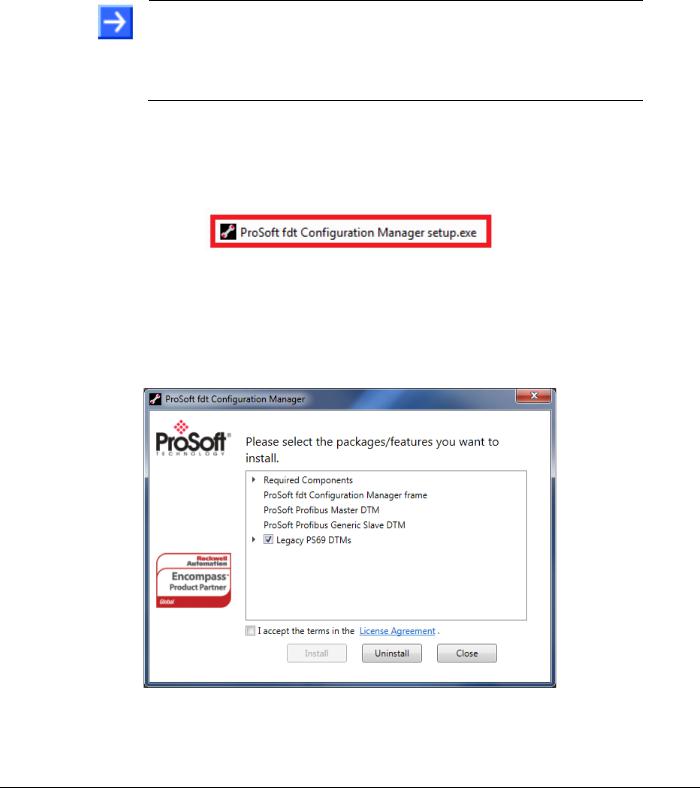
2Double-click ProSoft fdt Configuration Manager setup.exe from the DVD.
3Select Yes at the Windows® security question.
4Alternatively, you can reduce the number of Windows® safety questions by running the
setup via Run as Administrator. Right-click on the ProSoft fdt Configuration Manager.exe file and click Run as Administrator and answer the Windows® security question with Yes.
The ProSoft fdt Configuration Manager pane is displayed.
5If required, select Legacy PS69 DTMs if the PC running the new version of PROSOFT.fdt Configuration Manager is also going to be used to configure legacy ProSoft PS69-DPM modules.
Page 24 of 124 |
ProSoft Technology, Inc. |
|
February 4, 2015 |

ILX69-PBM ♦ CompactLogix or MicroLogix Platform |
Contents |
PROFIBUS Master Communication Module |
User Manual |
|
|
6When ready, select the I accept the terms in the License Agreement box.
7Click Install to continue the installation.
The installation will take several minutes.
ProSoft Technology, Inc. |
Page 25 of 124 |
February 4, 2015 |
|

Contents |
ILX69-PBM ♦ CompactLogix or MicroLogix Platform |
User Manual |
PROFIBUS Master Communication Module |
|
|
8 Click Close when installation is complete. |
|
The ProSoft fdt Configuration Manager is now installed. It can be launched from the Windows Start menu.
4.3ILX69-PBM Hardware Installation
This section describes how to install/uninstall the ILX69-PBM in a CompactLogix™ system.
4.3.1 Safety Precautions
Obey the following property damage messages when installing, uninstalling or replacing the ILX69-PBM.
Electrostatically sensitive devices
To prevent damage to the PLC and the ILX69-PBM, make sure that the ILX69-PBM is grounded via the backplane of the PLC. Also make sure that you are discharged when you install/uninstall the ILX69-PBM.
Device Destruction
Shut off the power supply of the PLC before you install the ILX69-PBM. Then install or remove the ILX69-PBM to/from the PLC..
Use only the permissible supply voltage to operate the ILX69-PBM.
All I/O signal pins at the ILX69-PBM tolerate only the specified signaling voltage.
Page 26 of 124 |
ProSoft Technology, Inc. |
|
February 4, 2015 |

ILX69-PBM ♦ CompactLogix or MicroLogix Platform |
Contents |
PROFIBUS Master Communication Module |
User Manual |
|
|
4.3.2 Installing the ILX69-PBM Module
A detailed description the installation of communication modules in
CompactLogix™ systems can be found in the installation manual for the 1769 CompactLogix™ controller from Rockwell Automation.
1Install the ILX69-PBM into a free slot in the CompactLogix™ controller. Make sure it is within 2 slots of a power supply.
2Check that the bus lever of the ILX69-PBM is in the unlocked (fully right) position.
3Assemble the ILX69-PBM and the CompactLogix™ module together by using the upper and lower tongue-and-groove slots.
4Move the ILX69-PBM back along the tongue-and-groove slots until the bus connectors line up with each other.
5Move the ILX69-PBM bus lever fully to the left until it clicks. Ensure it is locked firmly in place.
6Attach and lock an end cap terminator to the ILX69-PBM by using the tongue-and- groove slots as before.
7Apply power to the Rockwell CompactLogix™ controller.
4.4Uninstalling ILX69-PBM Hardware
1Adhere to the safety precautions.
2Shut off the power of the Rockwell CompactLogix™ controller.
3Discharge yourself.
4Unlock the end cap bus terminator.
5Remove the end cap terminator from the ILX69-PBM by using the tongue-and-groove slots.
6Move the ILX69-PBM bus lever in the unlocked (fully right) position.
7Remove the ILX69-PBM along the tongue-and-groove slots.
8Reassemble the end cap terminator and the CompactLogix™ system together by using the upper and lower tongue-and-groove slots.
ProSoft Technology, Inc. |
Page 27 of 124 |
February 4, 2015 |
|

Contents |
ILX69-PBM ♦ CompactLogix or MicroLogix Platform |
User Manual |
PROFIBUS Master Communication Module |
|
|
Page 28 of 124 |
ProSoft Technology, Inc. |
|
February 4, 2015 |
ILX69-PBM ♦ CompactLogix or MicroLogix Platform |
Contents |
||
PROFIBUS Master Communication Module |
User Manual |
||
5 |
Configuration and Start-Up |
|
|
|
In This Chapter |
|
|
|
|
CompactLogix Project............................................................................ |
29 |
|
ProSoft fdt Configuration Manager ........................................................ |
37 |
|
|
Downloading the Project to the ILX69-PBM........................................... |
45 |
|
|
Adjusting Input/Output Data Lengths in the Project ............................... |
51 |
|
|
|
Project Storage ...................................................................................... |
56 |
|
This chapter provides descriptions about the configuration and start-up of the ILX69-PBM. |
||
ILX69-PBM Configuration and Parameterization Steps:
The configuration and parameterization of the ILX69-PBM is carried out in three steps:
1Configuration of the module in a CompactLogix™ project using the Studio 5000 or
RSLogix 5000 programming tool.
2Parameterization and configuration of the ILX69-PBM with the ProSoft fdt Configuration Manager configuration software.
3Creating the data objects and the ladder diagram in Studio 5000/RSLogix 5000.
5.1CompactLogix Project
This section covers the configuration of the ILX69-PBM in a CompactLogix™ system.
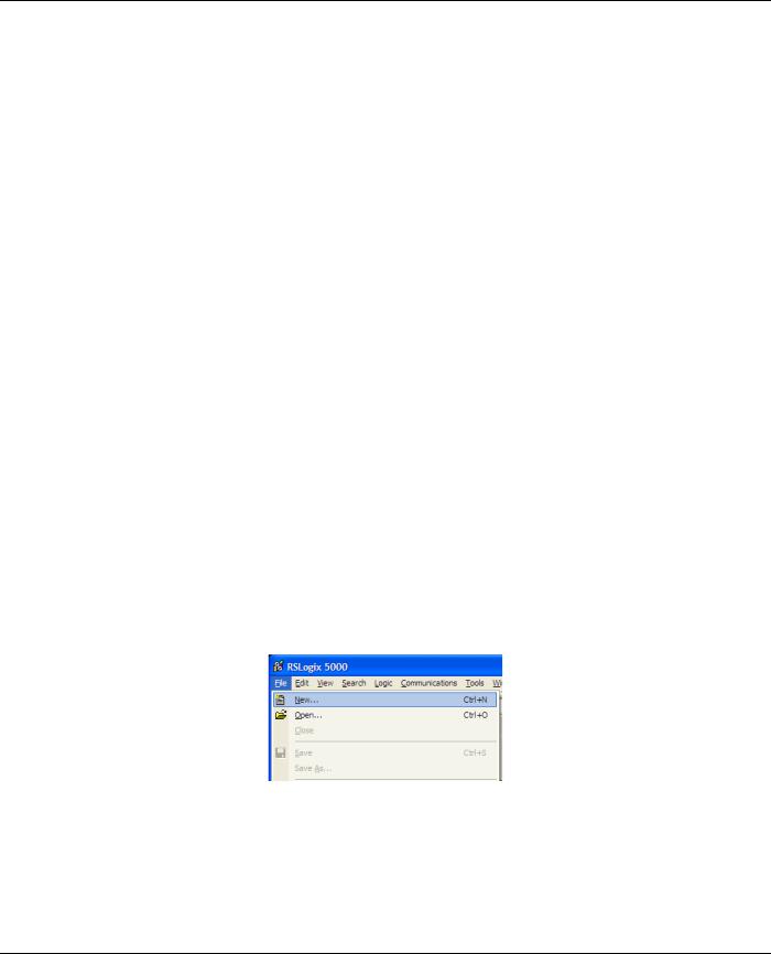
5.1.1 Creating a New Project
1 Open the FILE menu, and select NEW.
ProSoft Technology, Inc. |
Page 29 of 124 |
February 4, 2015 |
|

Contents |
ILX69-PBM ♦ CompactLogix or MicroLogix Platform |
User Manual |
PROFIBUS Master Communication Module |
|
|
2 |
Select your controller TYPE and REVISION 16 or newer. |
3Click OK.
4Right click on the I/O configuration > CompactBus Local of the controller project.
5Select New Module from the context menu as shown below.
Page 30 of 124 |
ProSoft Technology, Inc. |
|
February 4, 2015 |
 Loading...