


MVI69E-MBTCP

MVI69E-MBTCP
CompactLogix Platform
Modbus TCP/IP Enhanced
Communication Module
May 20, 2015
USER MANUAL

Your Feedback Please
We always want you to feel that you made the right decision to use our products. If you have suggestions, comments,
compliments or complaints about our products, documentation, or support, please write or call us.
ProSoft Technology
5201 Truxtun Ave., 3rd Floor
Bakersfield, CA 93309
+1 (661) 716-5100
+1 (661) 716-5101 (Fax)
www.prosoft-technology.com
support@prosoft-technology.com
MVI69E-MBTCP User Manual
May 20, 2015
ProSoft Technology
®
, is a registered copyright of ProSoft Technology, Inc. All other brand or product names are or
may be trademarks of, and are used to identify products and services of, their respective owners.
In an effort to conserve paper, ProSoft Technology no longer includes printed manuals with our product shipments.
User Manuals, Datasheets, Sample Ladder Files, and Configuration Files are provided on the enclosed DVD and are
available at no charge from our web site: http://www.prosoft-technology.com
Content Disclaimer
This documentation is not intended as a substitute for and is not to be used for determining suitability or reliability of
these products for specific user applications. It is the duty of any such user or integrator to perform the appropriate
and complete risk analysis, evaluation and testing of the products with respect to the relevant specific application or
use thereof. Neither ProSoft Technology nor any of its affiliates or subsidiaries shall be responsible or liable for
misuse of the information contained herein. Information in this document including illustrations, specifications and
dimensions may contain technical inaccuracies or typographical errors. ProSoft Technology makes no warranty or
representation as to its accuracy and assumes no liability for and reserves the right to correct such inaccuracies or
errors at any time without notice. If you have any suggestions for improvements or amendments or have found errors
in this publication, please notify us.
No part of this document may be reproduced in any form or by any means, electronic or mechanical, including
photocopying, without express written permission of ProSoft Technology. All pertinent state, regional, and local safety
regulations must be observed when installing and using this product. For reasons of safety and to help ensure
compliance with documented system data, only the manufacturer should perform repairs to components. When
devices are used for applications with technical safety requirements, the relevant instructions must be followed.
Failure to use ProSoft Technology software or approved software with our hardware products may result in injury,
harm, or improper operating results. Failure to observe this information can result in injury or equipment damage.
Copyright © 2015 ProSoft Technology, Inc. All Rights Reserved.
Printed documentation is available for purchase. Contact ProSoft Technology for pricing and availability.
North America: +1 (661) 716-5100
Asia Pacific: +603.7724.2080
Europe, Middle East, Africa: +33 (0) 5.3436.87.20
Latin America: +1.281.298.9109

Important Safety Information
North America Warnings
A This Equipment is Suitable For Use in Class I, Division 2, Groups A, B, C, D or Non-Hazardous Locations Only.
B Warning – Explosion Hazard – Substitution of Any Components May Impair Suitability for Class I, Division 2.
C Warning – Explosion Hazard – Do Not Disconnect Equipment Unless Power Has Been Switched Off Or The
Area is Known To Be Non-Hazardous.
D The subject devices are powered by a Switch Model Power Supply (SMPS) that has regulated output voltage of
5 VDC.
ATEX Warnings and Conditions of Safe Usage:
Power, Input, and Output (I/O) wiring must be in accordance with the authority having jurisdiction.
A Warning - Explosion Hazard - When in hazardous locations, turn off power before replacing or wiring modules.
B Warning - Explosion Hazard - Do not disconnect equipment unless power has been switched off or the area is
known to be non-hazardous.
C These products are intended to be mounted in an IP54 enclosure. The devices shall provide external means to
prevent the rated voltage being exceeded by transient disturbances of more than 40%. This device must be used
only with ATEX certified backplanes.
D DO NOT OPEN WHEN ENERGIZED.
Agency Approvals and Certifications
Agency
ATEX; Category 3, Zone 2
CE Mark
CSA; CB Safety
Environmental
KCC
RoHS Compliant
UL/cUL; Class 1, Div. 2 Groups A, B, C, D


MVI69E-MBTCP ♦ CompactLogix Platform Contents
Modbus TCP/IP Enhanced Communication Module User Manual
ProSoft Technology, Inc. Page 5 of 150
May 20, 2015
Contents
Your Feedback Please ........................................................................................................................ 2
Content Disclaimer .............................................................................................................................. 2
Important Safety Information ............................................................................................................... 3
1 Start Here 9
1.1 System Requirements ............................................................................................. 10
1.2 Deployment Checklist .............................................................................................. 11
1.3 Setting Jumpers ...................................................................................................... 11
1.4 Installing the Module in the Rack ............................................................................ 12
1.5 DVD Contents ......................................................................................................... 15
1.6 Package Contents ................................................................................................... 15
2 Adding the Module to RSLogix 17
2.1 Creating the Module in an RSLogix 5000 Project ................................................... 17
2.1.1 Creating a Module in the Project Using an Add-On Profile ..................................... 18
2.1.2 Creating a Module in the Project Using a Generic 1769 Module Profile ................. 21
2.2 Installing ProSoft Configuration Builder .................................................................. 24
2.3 Generating the AOI (.L5X File) in ProSoft Configuration Builder ............................ 25
2.3.1 Setting Up the Project in PCB ................................................................................. 25
2.3.2 Creating and Exporting the .L5X File ...................................................................... 27
2.4 Creating a New RSLogix 5000 Project .................................................................... 30
2.5 Importing the Add-On Instruction ............................................................................ 31
2.6 Adding Multiple Modules in the Rack (Optional) ..................................................... 34
2.6.1 Adding an Additional Module in PCB ...................................................................... 34
2.6.2 Adding an Additional Module in RSLogix 5000 ....................................................... 36
3 Configuring the MVI69E-MBTCP Using PCB 43
3.1 Basic PCB Functions ............................................................................................... 44
3.1.1 Creating a New PCB Project and Exporting an .L5X File ....................................... 44
3.1.2 Renaming PCB Objects .......................................................................................... 44
3.1.3 Editing Configuraiton Parameters ........................................................................... 44
3.1.4 Printing a Configuration File .................................................................................... 46
3.2 Module Configuration Parameters .......................................................................... 47
3.2.1 Module ..................................................................................................................... 47
3.2.2 MBTCP Servers ...................................................................................................... 48
3.2.3 MBTCP Client x ....................................................................................................... 50
3.2.4 MBTCP Client x Commands ................................................................................... 51
3.2.5 Ethernet 1 ................................................................................................................ 54
3.2.6 Static ARP Table ..................................................................................................... 55
3.3 Downloading the Configuration File to the Processor ............................................. 56
3.4 Uploading the Configuration File from the Processor ............................................. 59
4 MVI69E-MBTCP Backplane Data Exchange 63
4.1 General Concepts of the MVI69E-MBTCP Data Transfer ...................................... 63

Contents MVI69E-MBTCP ♦ CompactLogix Platform
User Manual Modbus TCP/IP Enhanced Communication Module
Page 6 of 150 ProSoft Technology, Inc.
May 20, 2015
4.2 Backplane Data Transfer ........................................................................................ 64
4.3 Normal Data Transfer ............................................................................................. 65
4.3.1 Write Block: Request from the Processor to the Module ........................................ 65
4.3.2 Read Block: Response from the Module to the Processor ..................................... 65
4.3.3 Read and Write Block Transfer Sequences ........................................................... 66
4.4 Data Flow Between the Module and Processor ..................................................... 70
4.4.1 Server Mode ........................................................................................................... 70
4.4.2 Master Mode ........................................................................................................... 72
5 Using Controller Tags 75
5.1 Controller Tags ....................................................................................................... 75
5.1.1 MVI69E-MBTCP Controller Tags ............................................................................ 76
5.2 User-Defined Data Types (UDTs)........................................................................... 76
5.2.1 MVI69E-MBTCP User-Defined Data Types ........................................................... 77
5.3 MBTCP Controller Tag Overview ........................................................................... 79
5.3.1 MBTCP.CONFIG .................................................................................................... 79
5.3.2 MBTCP.DATA ......................................................................................................... 80
5.3.3 MBTCP.CONTROL ................................................................................................. 80
5.3.4 MBTCP.STATUS .................................................................................................... 86
5.3.5 MBTCP.UTIL ........................................................................................................... 89
6 Diagnostics and Troubleshooting 93
6.1 Ethernet LED Indicators .......................................................................................... 93
6.2 LED Status Indicators ............................................................................................. 94
6.2.1 Clearing a Fault Condition ...................................................................................... 94
6.2.2 Troubleshooting ...................................................................................................... 95
6.3 Connecting the PC to the Module's Ethernet Port .................................................. 96
6.3.1 Setting Up a Temporary IP Address ....................................................................... 96
6.4 Using the Diagnostics Menu in ProSoft Configuration Builder ............................... 98
6.4.1 Diagnostics Menu ................................................................................................. 100
6.4.2 Monitoring General Information ............................................................................ 101
6.4.3 Monitoring Backplane Information ........................................................................ 101
6.4.4 Modbus Server Driver Information ........................................................................ 102
6.4.5 Monitoring Data Values in the Module’s Database............................................... 103
6.4.6 Modbus Client Driver Information ......................................................................... 103
6.5 Communication Error Codes ................................................................................ 104
6.5.1 Standard MODBUS Protocol Exception Code Errors ........................................... 104
6.5.2 Module Communication Error Codes ................................................................... 104
6.5.3 Command List Entry Errors .................................................................................. 104
6.5.4 MBTCP Client-Specific Errors .............................................................................. 105
6.6 Connecting to the Module’s Webpage .................................................................. 105
7 Reference 107
7.1 Product Specifications .......................................................................................... 107
7.1.1 General Specifications - Modbus Client/Server .................................................... 108
7.1.2 Hardware Specifications ....................................................................................... 108
7.2 About the Modbus TCP/IP Protocol ...................................................................... 109
7.2.1 Modbus Client ....................................................................................................... 109
7.2.2 Modbus Server...................................................................................................... 110
7.2.3 Function Codes Supported by the Module ........................................................... 110

MVI69E-MBTCP ♦ CompactLogix Platform Contents
Modbus TCP/IP Enhanced Communication Module User Manual
ProSoft Technology, Inc. Page 7 of 150
May 20, 2015
7.2.4 Read Coil Status (Function Code 01) ................................................................... 111
7.2.5 Read Input Status (Function Code 02) .................................................................. 112
7.2.6 Read Holding Registers (Function Code 03) ........................................................ 113
7.2.7 Read Input Registers (Function Code 04) ............................................................. 114
7.2.8 Force Single Coil (Function Code 05) ................................................................... 115
7.2.9 Preset Single Register (Function Code 06) ........................................................... 116
7.2.10 Diagnostics (Function Code 08) ............................................................................ 117
7.2.11 Force Multiple Coils (Function Code 15) ............................................................... 119
7.2.12 Preset Multiple Registers (Function Code 16) ...................................................... 120
7.3 Floating-Point Support ........................................................................................... 121
7.3.1 ENRON Floating Point Support ............................................................................. 122
7.3.2 Configuring the Floating Point Data Transfer ........................................................ 122
7.4 Function Blocks ..................................................................................................... 127
7.4.1 Event Command Blocks (2000 to 2019) ............................................................... 128
7.4.2 Client Status Request/Response Blocks (3000 to 3019) ...................................... 129
7.4.3 Event Sequence Request Blocks (4000 to 4019) ................................................. 130
7.4.4 Event Sequence Command Error Status Blocks (4100 to 4119) .......................... 131
7.4.5 Get Queue and Event Sequence Block Counts Block (4200)............................... 132
7.4.6 Command Control Blocks (5001 to 5016) ............................................................. 132
7.4.7 Add Event with Data for Client Blocks (8000) ....................................................... 133
7.4.8 Get Event with Data Status Block (8100) .............................................................. 134
7.4.9 Get General Module Status Data Block (9250) ..................................................... 135
7.4.10 Set Driver and Command Active Bits Block (9500) .............................................. 136
7.4.11 Get Driver and Command Active Bits Block (9501) .............................................. 137
7.4.12 Pass-Through Formatted Block for Functions 6 and 16 with Word Data Block
(9956) 138
7.4.13 Pass-Through Formatted Block for Functions 6 and 16 with Float Data Block
(9957) 139
7.4.14 Pass-Through Formatted Block for Function 5 (9958) .......................................... 139
7.4.15 Pass-Through Formatted Block for Function 15 (9959) ........................................ 140
7.4.16 Pass-Through Formatted Block for Function 23 (9961) ........................................ 141
7.4.17 Pass-Through Block for Function 99 (9970) ......................................................... 141
7.4.18 Set Module Time Using Received Time Block (9972) .......................................... 142
7.4.19 Pass Module Time to Processor Block (9973) ...................................................... 143
7.4.20 Reset Status Block (9997)..................................................................................... 143
7.4.21 Warm-boot Control Block (9998) ........................................................................... 144
7.4.22 Cold-boot Control Block (9999) ............................................................................. 144
7.5 Ethernet Port Connection ...................................................................................... 145
7.5.1 Ethernet Cable Specifications ............................................................................... 145
8 Support, Service & Warranty 147
8.1 Contacting Technical Support ............................................................................... 147
8.2 Warranty Information ............................................................................................. 148
Index 149

MVI69E-MBTCP ♦ CompactLogix Platform
Modbus TCP/IP Enhanced Communication Module User Manual
ProSoft Technology, Inc. Page 8 of 150
May 20, 2015

MVI69E-MBTCP ♦ CompactLogix Platform Start Here
Modbus TCP/IP Enhanced Communication Module User Manual
ProSoft Technology, Inc. Page 9 of 150
May 20, 2015
1 Start Here
In This Chapter
System Requirements ........................................................................... 10
Deployment Checklist ............................................................................ 10
Setting Jumpers .................................................................................... 11
Installing the Module in the Rack ........................................................... 12
DVD Contents ....................................................................................... 15
Package Contents ................................................................................. 15
To get the most benefit from this User Manual, you should have the following
skills:
Rockwell Automation
®
RSLogix™ software: launch the program, configure
ladder logic, and transfer the ladder logic to the processor
Microsoft Windows: install and launch programs, execute menu commands,
navigate dialog boxes, and enter data
Hardware installation and wiring: install the module, and safely connect
Modbus and CompactLogix devices to a power source and to the MVI69E-
MBTCP module’s Ethernet port

Start Here MVI69E-MBTCP ♦ CompactLogix Platform
User Manual Modbus TCP/IP Enhanced Communication Module
Page 10 of 150 ProSoft Technology, Inc.
May 20, 2015
1.1 System Requirements
The MVI69E-MBTCP module requires the following minimum hardware and
software components:
Rockwell Automation CompactLogix
®
processor (firmware version 10 or
higher), with compatible power supply and one free slot in the rack, for the
MVI69E-MBTCP module.
Important: The MVI69E-MBTCP module has a power supply distance rating of 2 (L43 and L45
installations on first 2 slots of 1769 bus). It consumes 500 mA at 5 Vdc.
Important: For 1769-L23x processors, please make note of the following limitation:
1769-L23E-QBFC1B = 450 mA at 5 Vdc (No MVI69E module can be used with this processor.)
The module requires 500 mA of available 5 Vdc power
Rockwell Automation RSLogix 5000 programming software version 16 or
higher
Rockwell Automation RSLinx
®
communication software version 2.51 or higher
ProSoft Configuration Builder (PCB) (included)
ProSoft Discovery Service (PDS) (included in PCB)
Pentium
®
II 450 MHz minimum. Pentium III 733 MHz (or better)
recommended
Supported operating systems:
o Microsoft Windows
®
7
o Microsoft Windows Vista
o Microsoft Windows XP Professional with Service Pack 1 or 2
o Microsoft Windows 2000 Professional with Service Pack 1, 2, or 3
o Microsoft Windows Server 2003
128 Mbytes of RAM minimum, 256 Mbytes of RAM recommended
100 Mbytes of free hard disk space (or more based on application
requirements)
256-color VGA graphics adapter, 800 x 600 minimum resolution (True Color
1024 x 768 recommended)
DVD drive
Note: The Hardware and Operating System requirements in this list are the minimum
recommended to install and run software provided by ProSoft Technology
®
. Other third party
applications may have different minimum requirements. Refer to the documentation for any third
party applications for system requirements.
MVI69E-MBTCP ♦ CompactLogix Platform Start Here
Modbus TCP/IP Enhanced Communication Module User Manual
ProSoft Technology, Inc. Page 11 of 150
May 20, 2015
1.2 Deployment Checklist
Before you begin to configure the module, consider the following questions. Your
answers will help you determine the scope of your project, and the configuration
requirements for a successful deployment.
Are you creating a new application or integrating the module into an existing
application?
Most applications can use the Sample Add-On Instruction or Sample Ladder
Logic without any modification.
Which slot number in the chassis does the MVI69E-MBTCP module occupy?
For communication to occur, you must enter the correct slot number in the
sample program.
Are the RSLogix 5000 and RSLinx software installed?
RSLogix and RSLinx are required to communicate to the CompactLogix
processor.
How many words of data do you need to transfer in your application (from
CompactLogix to Module / to CompactLogix from Module)?
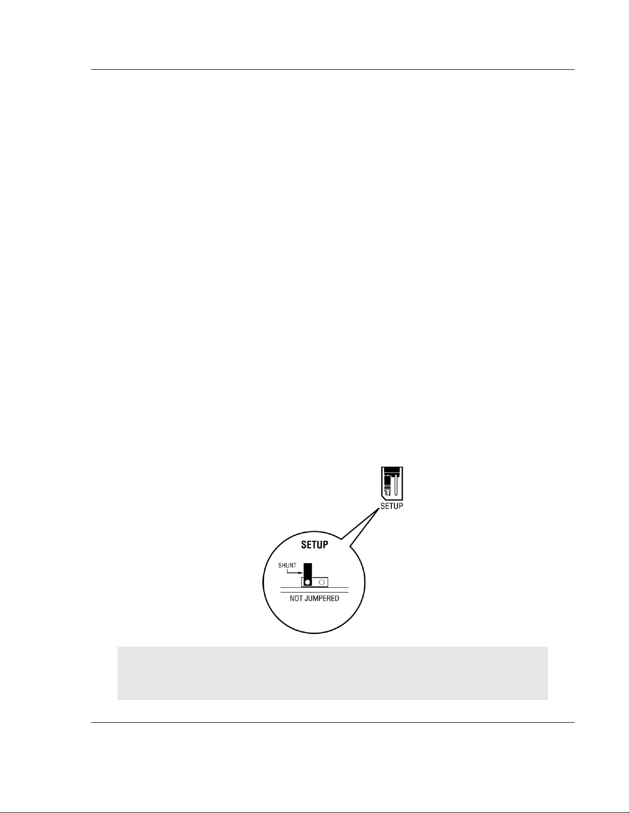
1.3 Setting Jumpers
The Setup Jumper acts as "write protection" for the module’s firmware. In "write
protected" mode, the Setup pins are not connected, and the module’s firmware
cannot be overwritten. The module is shipped with the Setup jumper OFF. Do not
jumper the Setup pins together unless you are directed to do so by ProSoft
Technical Support (or you want to update the module firmware).
The following illustration shows the MVI69E-MBTCP jumper configuration with
the Setup Jumper OFF.
Note: If you are installing the module in a remote rack, you may prefer to leave the Setup pins
jumpered. That way, you can update the module’s firmware without requiring physical access to
the module.
Start Here MVI69E-MBTCP ♦ CompactLogix Platform
User Manual Modbus TCP/IP Enhanced Communication Module
Page 12 of 150 ProSoft Technology, Inc.
May 20, 2015
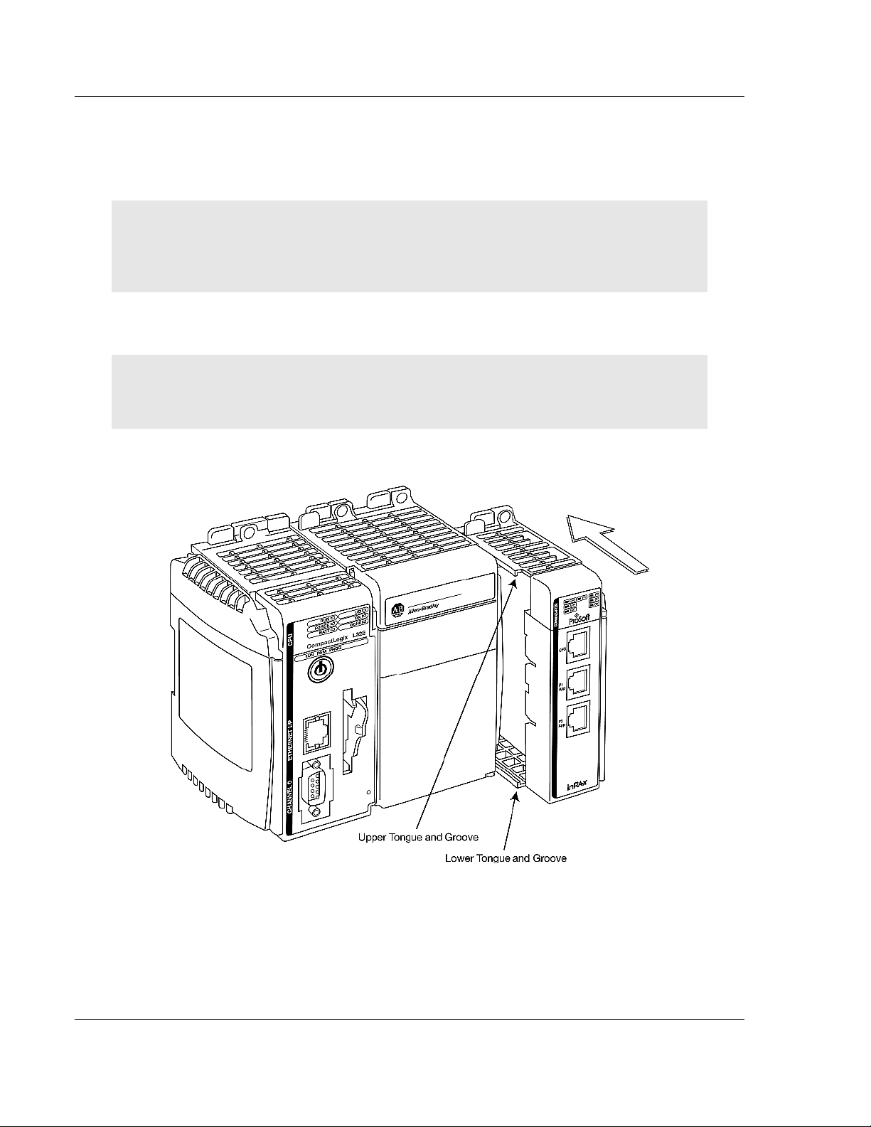
1.4 Installing the Module in the Rack
Make sure the processor and power supply are installed and configured before
installing the MVI69E-MBTCP module. Refer to the Rockwell Automation product
documentation for installation instructions.
Warning: Please follow all safety instructions when installing this or any other electronic devices.
Failure to follow safety procedures could result in damage to hardware or data, or even serious
injury or death to personnel. Refer to the documentation for each device to be connected to verify
that suitable safety procedures are in place before installing or servicing the device.
After you verify the jumper placements, insert the MVI69E-MBTCP into the rack.
Use the same technique recommended by Rockwell Automation to remove and
install CompactLogix modules.
Warning: This module is not hot-swappable! Always remove power from the rack before
inserting or removing this module, or damage may result to the module, the processor, or other
connected devices.
1 Align the module using the upper and lower tongue-and-groove slots with the
adjacent module and slide forward in the direction of the arrow.
2 Move the module back along the tongue-and-groove slots until the bus
connectors on the MVI69 module and the adjacent module line up with each
other.
MVI69E-MBTCP ♦ CompactLogix Platform Start Here
Modbus TCP/IP Enhanced Communication Module User Manual
ProSoft Technology, Inc. Page 13 of 150
May 20, 2015
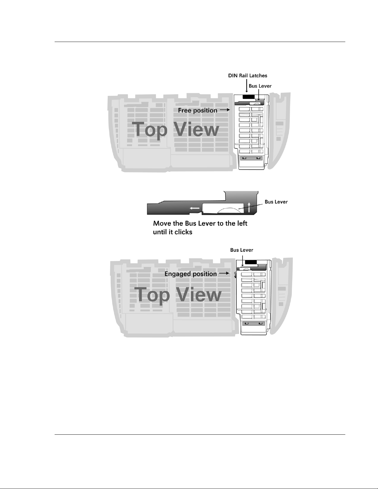
3 Push the module’s bus lever back slightly to clear the positioning tab and
move it firmly to the left until it clicks. Ensure that it is locked firmly in place.
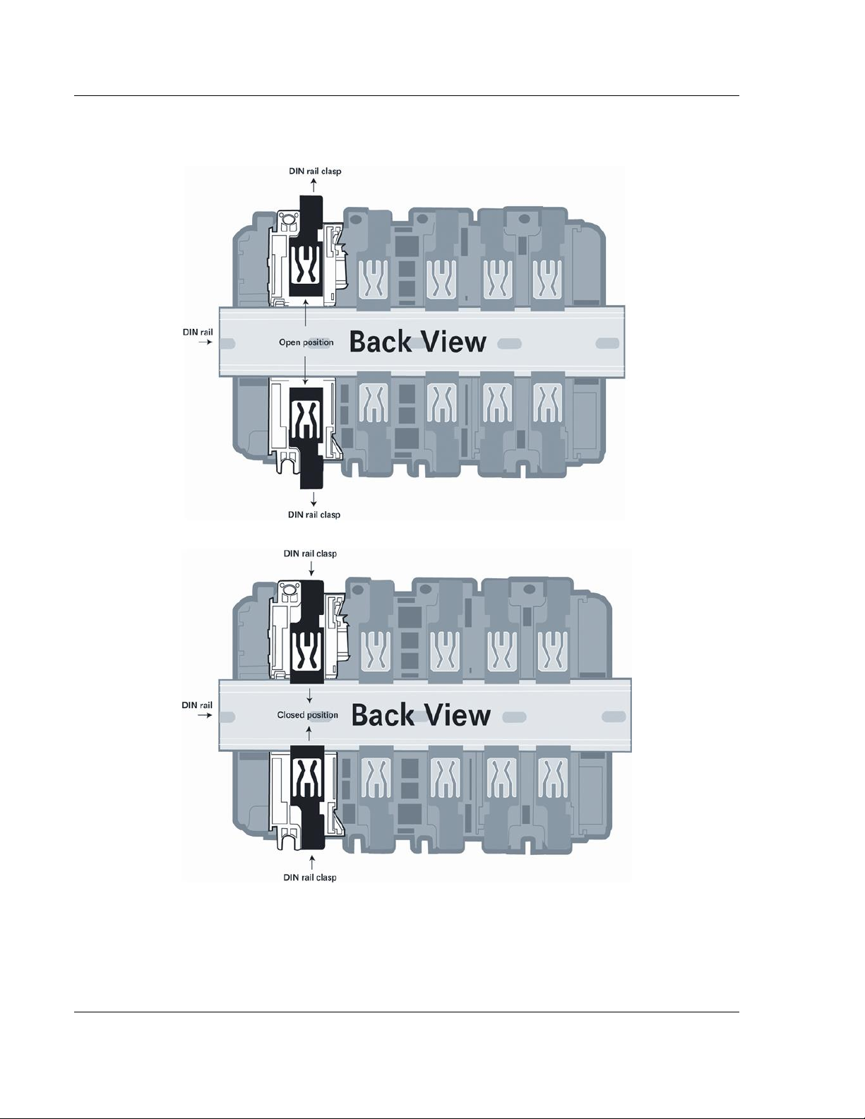
4 Close all DIN-rail latches.
Start Here MVI69E-MBTCP ♦ CompactLogix Platform
User Manual Modbus TCP/IP Enhanced Communication Module
Page 14 of 150 ProSoft Technology, Inc.
May 20, 2015
5 Press the DIN-rail mounting area of the controller against the DIN-rail. The
latches momentarily open and lock into place.

MVI69E-MBTCP ♦ CompactLogix Platform Start Here
Modbus TCP/IP Enhanced Communication Module User Manual
ProSoft Technology, Inc. Page 15 of 150
May 20, 2015
1.5 DVD Contents
The DVD contains all the necessary files for the module including the User
Manual and the ProSoft Configuration Builder (PCB) software. It also may
contain module-specific configuration files such as the RSLogix 5000 Add-On
Profile and sample Add-On Instruction (where applicable to the module).
If the DVD is not present, please visit http://www.prosoft-technology.com for the
latest files.
1.6 Package Contents
The following components are included with your MVI69E-MBTCP module, and
are all required for installation and configuration.
Important: Before beginning the installation, please verify that all of the following items are
present.
Qty.
Part Name
Part Number
Part Description
1
MVI69E-MBTCP Module
MVI69E-MBTCP
Modbus TCP/IP Enhanced
Communication Module
1
Ethernet Cable
RL-CBL025
Straight-through Ethernet cable
1
ProSoft Solutions DVD
DVD-001
Contains sample programs, ProSoft
Configuration Builder (PCB), and
documentation.
If any of these components are missing, please contact ProSoft Technology
Technical Support for replacement parts. For the latest files, or if the DVD is not
present, please visit http://www.prosoft-technology.com.

MVI69E-MBTCP ♦ CompactLogix Platform
User Manual Modbus TCP/IP Enhanced Communication Module
Page 16 of 150 ProSoft Technology, Inc.
May 20, 2015

MVI69E-MBTCP ♦ CompactLogix Platform Adding the Module to RSLogix
Modbus TCP/IP Enhanced Communication Module User Manual
ProSoft Technology, Inc. Page 17 of 150
May 20, 2015
2 Adding the Module to RSLogix
In This Chapter
Creating the Module in an RSLogix 5000 Project .................................. 17
Installing ProSoft Configuration Builder ................................................. 24
Generating the AOI (.L5X File) in ProSoft Configuration Builder ........... 25
Creating a New RSLogix 5000 Project .................................................. 30
Importing the Add-On Instruction ........................................................... 31
Adding Multiple Modules in the Rack (Optional) .................................... 34
To add the MVI69E-MBTCP module in RSLogix 5000, you must:
1 Create a new project in RSLogix 5000.
2 Add the module to the RSLogix 5000 project. There are two ways to do this:
o You can use the Add-On Profile from ProSoft Technology. This is the
preferred way, but requires RSLogix version 15 or later.
o You can manually create the module using a generic 1769 profile, and
then manually configure the module parameters. Use this method if you
have RSLogix version 14 or earlier.
3 Create an Add-On Instruction file using ProSoft Configuration Builder (PCB)
and export the Add-On Instruction to an RSLogix 5000 compatible file (.L5X
file).
4 Import the Add-On Instruction (the .L5X file) into RSLogix 5000.
The .L5X file contains the Add-On Instruction, user-defined data types, controller
tags and ladder logic required to configure the MVI69E-MBTCP module.
2.1 Creating the Module in an RSLogix 5000 Project
In an RSLogix 5000 project, there are two ways you can add the MVI69E-
MBTCP module to the project.
You can use an Add-On Profile (AOP) from ProSoft Technology. The AOP
contains all the configuration information needed to add the module to the
project. This is the preferred way, but requires RSLogix version 15 or later.
Refer to Creating a Module in the Project Using an Add-On Profile (page 18).
If using an AOP is not an option, you can manually create and configure the
module using a generic 1769 profile. Use this method if you have RSLogix
version 14 or earlier. Refer to Creating a Module in the Project Using a
Generic 1769 Module Profile (page 21).
Adding the Module to RSLogix MVI69E-MBTCP ♦ CompactLogix Platform
User Manual Modbus TCP/IP Enhanced Communication Module
Page 18 of 150 ProSoft Technology, Inc.
May 20, 2015
2.1.1 Creating a Module in the Project Using an Add-On Profile
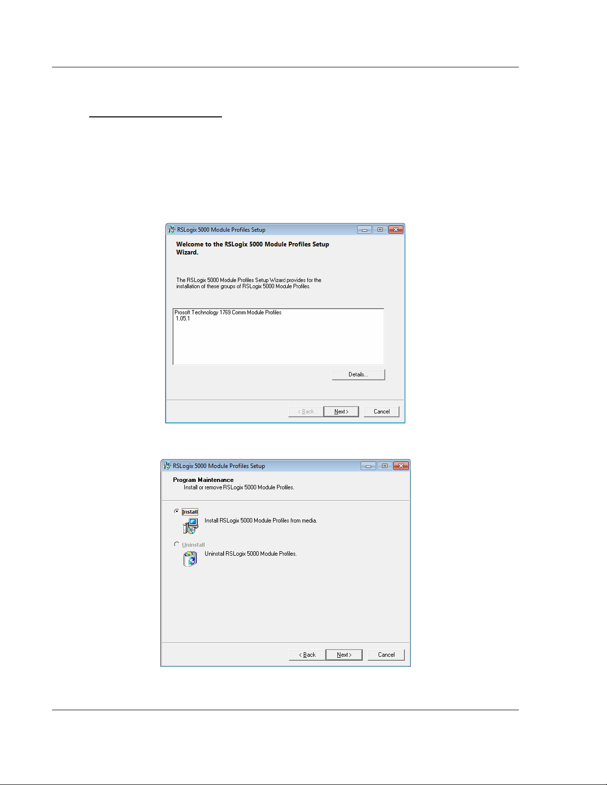
Installing an Add-On Profile
Download the AOP file (MVI69x_RevX.X_AOP.zip) from the product webpage
(found at http://www.prosoft-technology.com) or from the ProSoft Solutions DVD
onto your local hard drive and then extract the files from the zip archive. Make
sure you have shut down RSLogix 5000 and RSLinx before you install the Add-
On Profile (AOP).
Run the MPSetup.exe file to start the Setup Wizard. Follow the Setup Wizard to
install the AOP.
Continue to follow the steps in the wizard to complete the installation.

MVI69E-MBTCP ♦ CompactLogix Platform Adding the Module to RSLogix
Modbus TCP/IP Enhanced Communication Module User Manual
ProSoft Technology, Inc. Page 19 of 150
May 20, 2015
Click FINISH when complete. The AOP is now installed in RSLogix 5000. You do
not need to reboot the PC.
Using an Add-On Profile
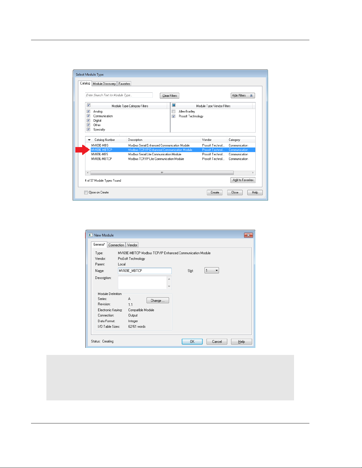
1 In RSLogix 5000, expand the I/O CONFIGURATION folder in the Project tree.
Right-click the appropriate communications bus and choose NEW MODULE.
This opens the Select Module Type dialog box.
Adding the Module to RSLogix MVI69E-MBTCP ♦ CompactLogix Platform
User Manual Modbus TCP/IP Enhanced Communication Module
Page 20 of 150 ProSoft Technology, Inc.
May 20, 2015
2 In the Module Type Vendor Filters area, uncheck all boxes except the
PROSOFT TECHNOLOGY box. A list of ProSoft Technology modules appears.
3 Select the MVI69E-MBTCP module in the list and click CREATE.
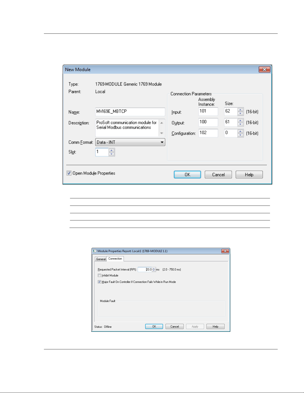
4 In the New Module dialog box, edit the NAME and SLOT. Click OK.
Note : The I/O TABLE SIZES above should reflect the Block Transfer Size parameter set in ProSoft
Configuration Builder (see Module Configuration Parameters (page 47)).
A Block Transfer Size of 60 uses an I/O TABLE SIZE of 62/61 words.
A Block Transfer Size of 120 uses an I/O TABLE SIZE of 122/121 words.
A Block Transfer Size of 240 uses an I/O TABLE SIZE of 242/241 words.
MVI69E-MBTCP ♦ CompactLogix Platform Adding the Module to RSLogix
Modbus TCP/IP Enhanced Communication Module User Manual
ProSoft Technology, Inc. Page 21 of 150
May 20, 2015
The MVI69E-MBTCP module is now visible in the I/O Configuration tree.
2.1.2 Creating a Module in the Project Using a Generic 1769 Module
Profile
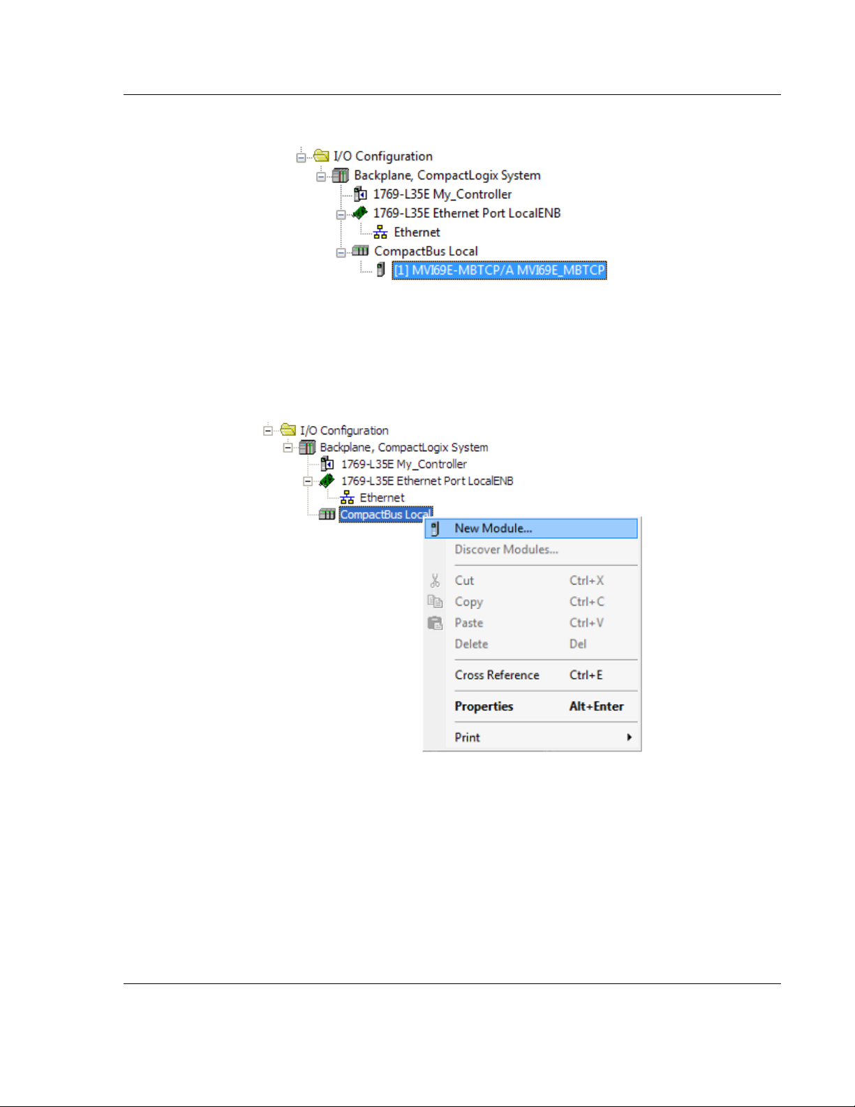
1 Expand the I/O CONFIGURATION folder in the Project tree. Right-click the
appropriate communications bus and choose NEW MODULE.
This opens the Select Module Type dialog box.
Adding the Module to RSLogix MVI69E-MBTCP ♦ CompactLogix Platform
User Manual Modbus TCP/IP Enhanced Communication Module
Page 22 of 150 ProSoft Technology, Inc.
May 20, 2015
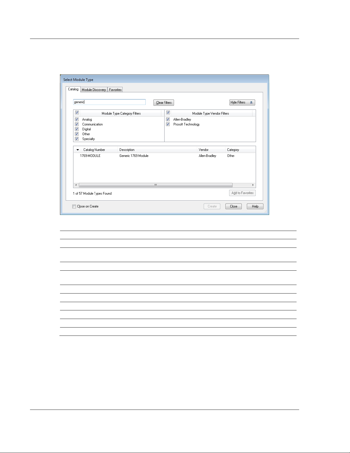
2 Enter GENERIC in the search text box and select the GENERIC 1769 MODULE. If
you're using an earlier version of RSLogix, expand OTHER in the Select
Module dialog box, and then select the GENERIC 1769 MODULE.
3 Set the Module Properties values as follows:
Parameter
Value
Name
Enter a module identification string. Example: MVI69E_MBTCP
Description
Enter a description for the module. Example: ProSoft
communication module for Serial Modbus communications.
Comm Format
Select DATA-INT
Slot
Enter the slot number in the rack where the MVI69E-MBTCP
module is installed.
Input Assembly Instance
101
Input Size
62 / 122 / 242
Output Assembly Instance
100
Output Size
61 / 121 / 241
Configuration Assembly Instance
102
Configuration Size
0
MVI69E-MBTCP ♦ CompactLogix Platform Adding the Module to RSLogix
Modbus TCP/IP Enhanced Communication Module User Manual
ProSoft Technology, Inc. Page 23 of 150
May 20, 2015
The following illustration shows an example where the module was
configured for a block transfer size of 60 words (input block size = 62 words,
output block size = 61 words):
The following options are available:
Block Transfer Size
Input Block Size
Output Block Size
60
62
61
120
122
121
240
242
241
4 On the Connection tab, set the REQUESTED PACKET INTERVAL value for your
project and click OK.

Adding the Module to RSLogix MVI69E-MBTCP ♦ CompactLogix Platform
User Manual Modbus TCP/IP Enhanced Communication Module
Page 24 of 150 ProSoft Technology, Inc.
May 20, 2015
The MVI69E-MBTCP module is now visible in the I/O Configuration tree.
2.2 Installing ProSoft Configuration Builder
Use the ProSoft Configuration Builder (PCB) software to configure the module.
You can find the latest version of the ProSoft Configuration Builder (PCB) on our
web site: http://www.prosoft-technology.com, or you can install it from the ProSoft
Solutions DVD. The installation filename contains the PCB version number. For
example, PCB_4.3.4.5.0238.EXE.
If you are installing PCB from the ProSoft website:
1 Open a browser window and navigate to
http://www.prosoft-technology.com/pcb.
2 Click the download link for ProSoft Configuration Builder, and save the file to
your Windows desktop.
3 After the download completes, double-click the file to install. If you are using
Windows 7, right-click the PCB installation file and then choose RUN AS
ADMINISTRATOR. Follow the instructions that appear on the screen.
4 If you want to find additional software specific to your MVI69E-MBTCP, enter
the model number into the ProSoft website search box and press the Enter
key.
If you are installing PCB from the ProSoft Solutions DVD:
1 Insert the ProSoft Solutions DVD into your computer's DVD drive and wait for
the ProSoft Installation program to start.
2 If the ProSoft Installation program does not start, open the Windows file
Explorer, navigate to the DVD, and double-click the ProSoft_DVD.exe file.
3 Navigate to the MVI69E-MBTCP selection using the PLATFORM and PRODUCT
selections.
4 Click PROSOFT CONFIGURATION BUILDER.
5 Follow the instructions that appear on the screen.
MVI69E-MBTCP ♦ CompactLogix Platform Adding the Module to RSLogix
Modbus TCP/IP Enhanced Communication Module User Manual
ProSoft Technology, Inc. Page 25 of 150
May 20, 2015
2.3 Generating the AOI (.L5X File) in ProSoft Configuration Builder
The following sections describe the steps required to set up a new configuration
project in ProSoft Configuration Builder (PCB), and to export the .L5X file for the
project.
2.3.1 Setting Up the Project in PCB
To begin, start PROSOFT CONFIGURATION BUILDER (PCB).
The PCB window consists of a tree view on the left, and an information pane and
a configuration pane on the right side of the window. The tree view consists of
folders for Default Project and Default Location, with a Default Module in the
Default Location folder. The following illustration shows the PCB window with a
new project.
Adding the Module to RSLogix MVI69E-MBTCP ♦ CompactLogix Platform
User Manual Modbus TCP/IP Enhanced Communication Module
Page 26 of 150 ProSoft Technology, Inc.
May 20, 2015
Your first task is to add the MVI69E-MBTCP module to the project.
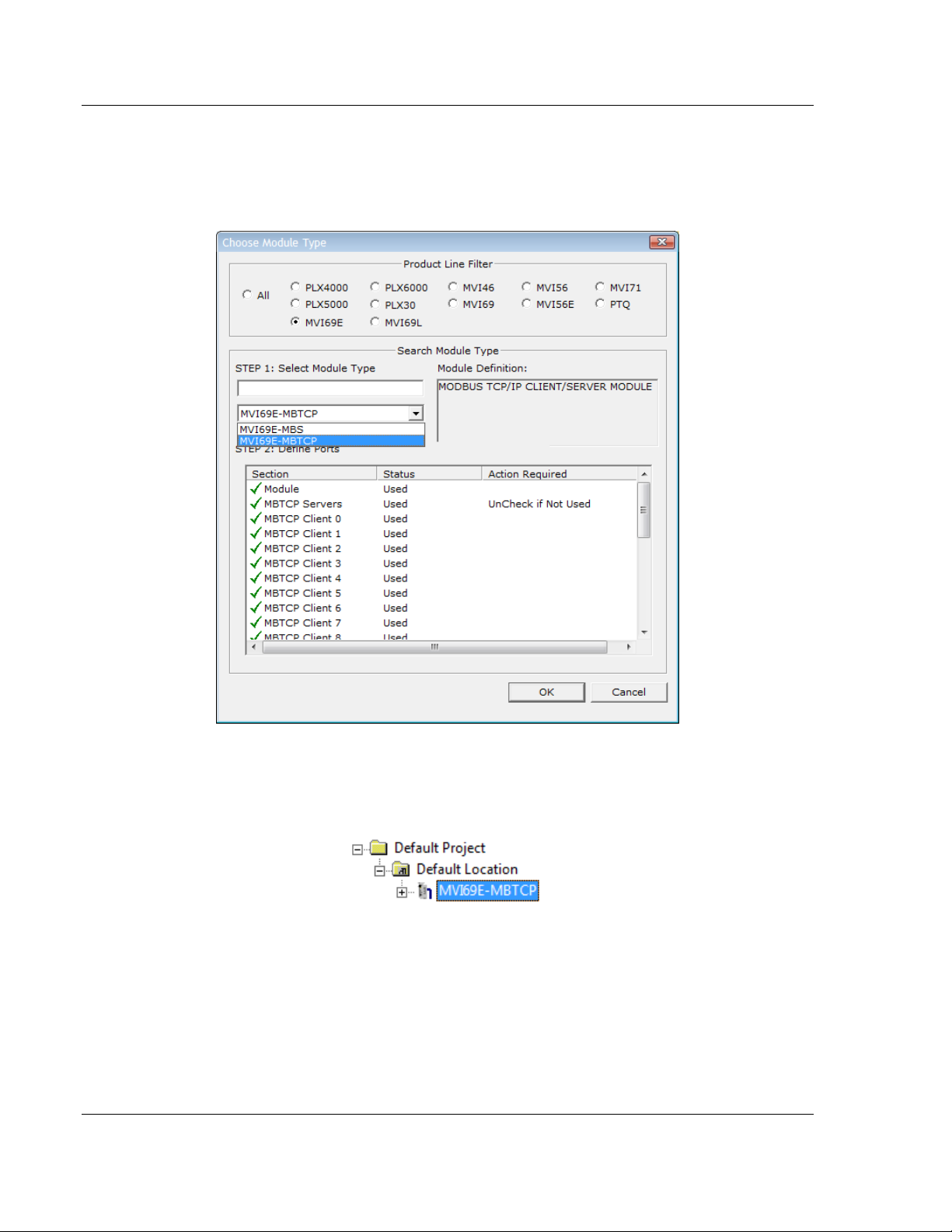
1 In the Tree view, right-click DEFAULT MODULE, and then choose CHOOSE
MODULE TYPE. This opens the Choose Module Type dialog box.
2 In the Product Line Filter area of the dialog box, click MVI69. In the Select
Module Type dropdown list, click MVI69E-MBTCP, and then click OK to save
your settings and return to the ProSoft Configuration Builder window. The
MVI69E-MBTCP icon is now visible in the tree view.
MVI69E-MBTCP ♦ CompactLogix Platform Adding the Module to RSLogix
Modbus TCP/IP Enhanced Communication Module User Manual
ProSoft Technology, Inc. Page 27 of 150
May 20, 2015
2.3.2 Creating and Exporting the .L5X File
There are two parameters in the PCB configuration that affect the format of the
.L5X file that is exported. Before exporting the .L5X file to the PC/Laptop, check
the Block Transfer Size and Slot Number parameters.
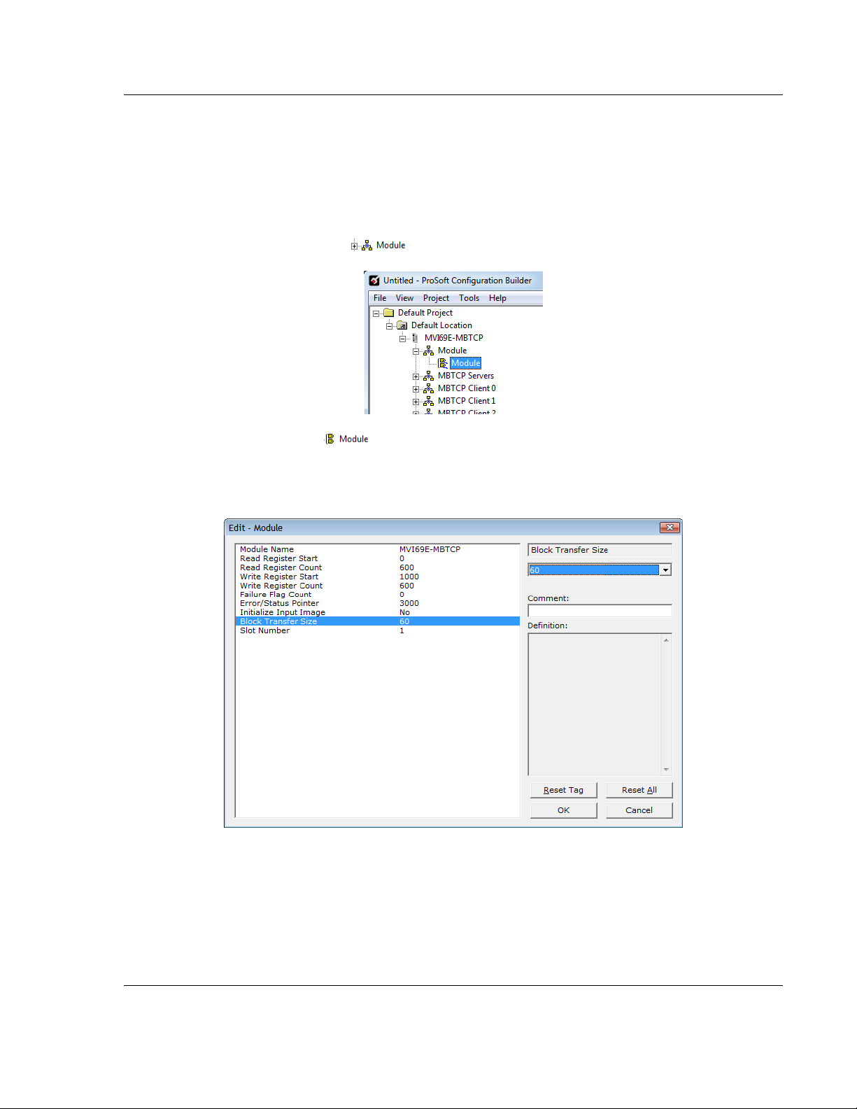
1 Expand the MVI69E-MBTCP icon by clicking the [+] symbol beside it.
Similarly, expand the icon.
2 Double-click the icon to open the Edit - Module dialog box.
3 Set the Block Transfer Size to the desired size of the data blocks transferred
between the module and processor (60, 120 or 240 words). You can find
block transfer size information starting in Normal Data Transfer (page 65).
Adding the Module to RSLogix MVI69E-MBTCP ♦ CompactLogix Platform
User Manual Modbus TCP/IP Enhanced Communication Module
Page 28 of 150 ProSoft Technology, Inc.
May 20, 2015
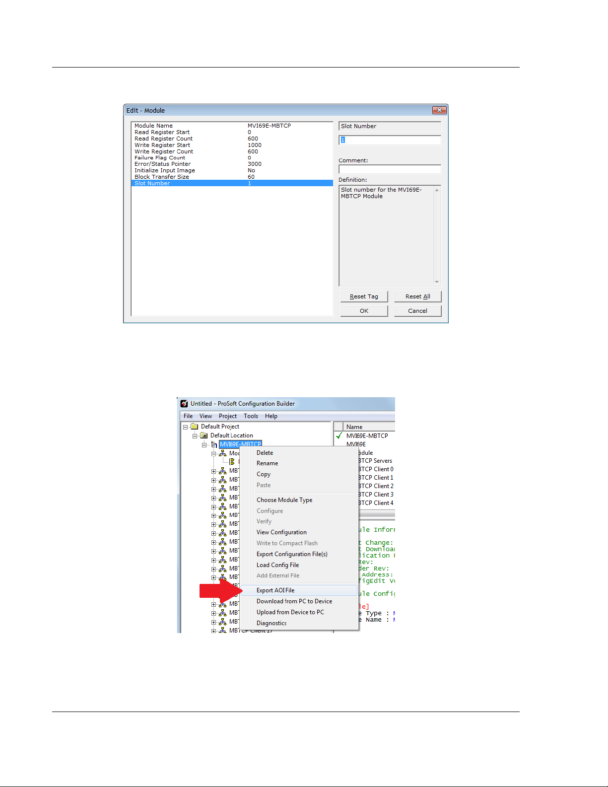
4 Edit the Slot Number indicating where the module is located in the 1769 bus.
5 Click OK to close the Edit – Module dialog box. The .L5X file is now ready to
export to the PC/Laptop.
6 Right-click the MVI69E-MBTCP icon in the project tree and choose EXPORT
AOI FILE.
MVI69E-MBTCP ♦ CompactLogix Platform Adding the Module to RSLogix
Modbus TCP/IP Enhanced Communication Module User Manual
ProSoft Technology, Inc. Page 29 of 150
May 20, 2015
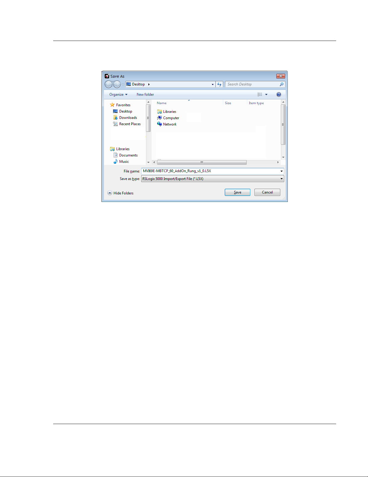
7 Save the .L5X file to the PC/Laptop in an easily found location, such as the
Windows Desktop.
Adding the Module to RSLogix MVI69E-MBTCP ♦ CompactLogix Platform
User Manual Modbus TCP/IP Enhanced Communication Module
Page 30 of 150 ProSoft Technology, Inc.
May 20, 2015
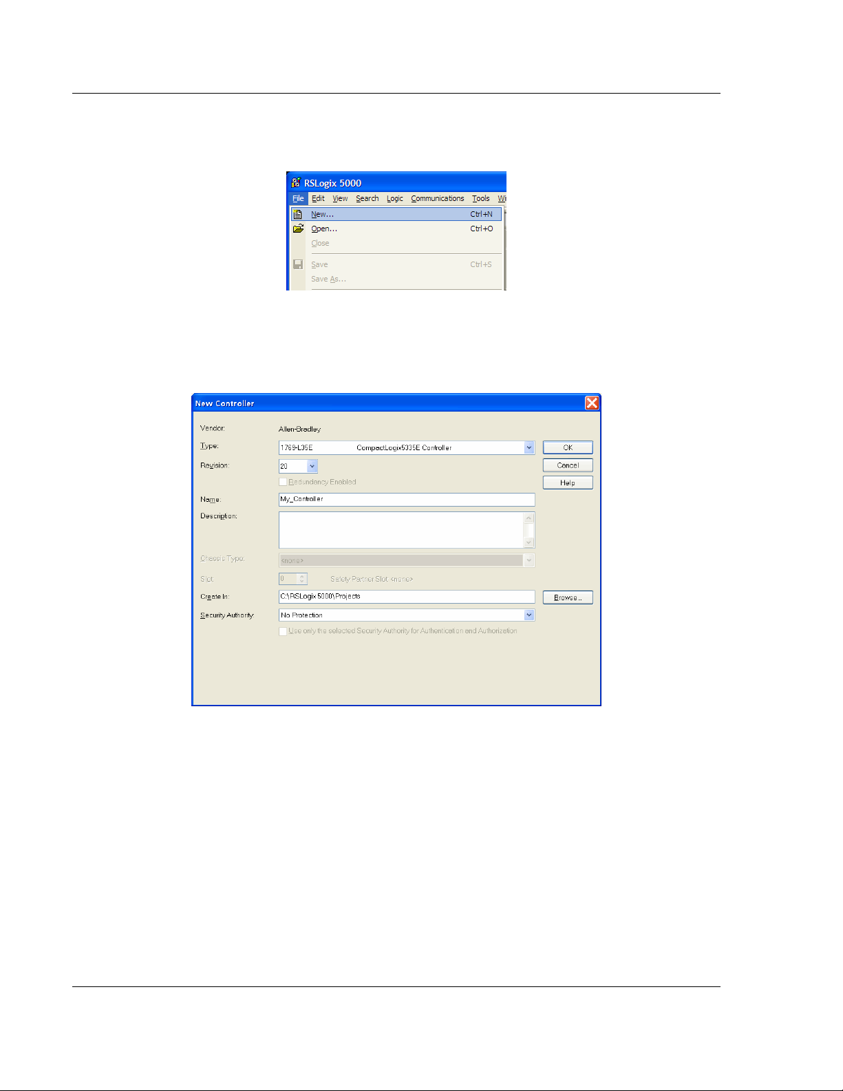
2.4 Creating a New RSLogix 5000 Project
1 Click the FILE menu and then choose NEW.
2 Select your CompactLogix controller model.
3 Select REVISION 16 or newer.
4 Enter a name for your controller, such as My_Controller.
5 Select your CompactLogix chassis type.
 Loading...