


PLX3x Series
Ethernet and Serial Gateways
September 17, 2014
USER MANUAL
Your Feedback Please
We always want you to feel that you made the right decision to use our products. If you have suggestions, comments, compliments or complaints about our products, documentation, or support, please write or call us.
How to Contact Us
ProSoft Technology
5201 Truxtun Ave., 3rd Floor Bakersfield, CA 93309
+1 (661) 716-5100
+1 (661) 716-5101 (Fax) www.prosoft-technology.com support@prosoft-technology.com
Copyright © 2014 ProSoft Technology, Inc., All rights reserved.
PLX3x Series Ethernet and Serial Gateways User Manual
September 17, 2014
ProSoft Technology ®, ProLinx®, inRAx ®, ProTalk ®, and RadioLinx ® are Registered Trademarks of ProSoft Technology, Inc. All other brand or product names are or may be trademarks of, and are used to identify products and services of, their respective owners.
ProSoft Technology® Product Documentation
In an effort to conserve paper, ProSoft Technology no longer includes printed manuals with our product shipments. User Manuals, Datasheets, Sample Ladder Files, and Configuration Files are provided on the enclosed DVD in Adobe® Acrobat Reader file format (.PDFs). These product documentation files may also be freely downloaded from our web site: http://www.prosoft-technology.com/
Literature Content Disclaimer
This documentation is not intended as a substitute for and is not to be used for determining suitability or reliability of these products for specific user applications. It is the duty of any such user or integrator to perform the appropriate and complete risk analysis, evaluation and testing of the products with respect to the relevant specific application or use thereof. Neither ProSoft Technology nor any of its affiliates or subsidiaries shall be responsible or liable for misuse of the information contained herein. Information in this document including illustrations, specifications and dimensions may contain technical inaccuracies or typographical errors. ProSoft Technology makes no warranty or representation as to its accuracy and assumes no liability for and reserves the right to correct such inaccuracies or errors at any time without notice. If you have any suggestions for improvements or amendments or have found errors in this publication, please notify us.
No part of this document may be reproduced in any form or by any means, electronic or mechanical, including photocopying, without express written permission of ProSoft Technology. All pertinent state, regional, and local safety regulations must be observed when installing and using this product. For reasons of safety and to help ensure compliance with documented system data, only the manufacturer should perform repairs to components. When devices are used for applications with technical safety requirements, the relevant instructions must be followed. Failure to use ProSoft Technology software or approved software with our hardware products may result in injury, harm, or improper operating results. Failure to observe this information can result in injury or equipment damage.
© 2014 ProSoft Technology. All rights reserved.

Important Installation Instructions
Power, Input, and Output (I/O) wiring must be in accordance with Class I, Division 2 wiring methods, Article 501-4 (b) of the National Electrical Code, NFPA 70 for installation in the U.S., or as specified in Section 18-1J2 of the Canadian Electrical Code for installations in Canada, and in accordance with the authority having jurisdiction. The following warnings must be heeded:
This Equipment is Suitable For Use in Class I, Division 2, Groups A, B, C, D or Non-Hazardous Locations Only
WARNING – Explosion Hazard – Substitution of Any Components May Impair Suitability for Class I, Division 2
WARNING – Explosion Hazard – Do Not Disconnect Equipment Unless Power Has Been Switched Off Or The Area is Known To Be Non-Hazardous
Agency Approvals and Certifications
CE Mark
UL/cUL Class I Div II
ATEX Zone 2
CB Safety
RoHS
PLX3x Series |
Contents |
Ethernet and Serial Gateways |
User Manual |
|
|
Contents
Your Feedback Please........................................................................................................................ |
2 |
How to Contact Us .............................................................................................................................. |
2 |
ProSoft Technology® Product Documentation .................................................................................... |
2 |
Literature Content Disclaimer ............................................................................................................. |
2 |
Important Installation Instructions ....................................................................................................... |
3 |
Agency Approvals and Certifications .................................................................................................. |
3 |
1 |
Start Here |
9 |
|
|
|
|
|
1.1 |
System Requirements ............................................................................................... |
9 |
|
1.2 |
Package Contents ................................................................................................... |
10 |
|
1.3 |
Mounting the Gateway on a DIN-rail ....................................................................... |
11 |
|
1.4 |
Jumper Settings ...................................................................................................... |
12 |
|
1.5 |
SD Card................................................................................................................... |
12 |
|
1.6 |
Connecting Power to the PLX3x Gateway .............................................................. |
13 |
|
2 |
Configuring Your Gateway |
15 |
|
|
|
|
|
2.1 |
Installing ProSoft Configuration Builder Software ................................................... |
16 |
|
2.2 |
Using the Online Help ............................................................................................. |
17 |
|
2.3 |
Setting Up the Project ............................................................................................. |
17 |
|
2.4 |
Renaming PCB Objects .......................................................................................... |
20 |
|
2.5 |
Configuring the Drivers............................................................................................ |
21 |
|
2.6 |
Using the CommonNet Data Map ........................................................................... |
25 |
|
2.7 |
Configuring an IP Address ...................................................................................... |
27 |
|
2.8 |
Downloading the Project to the Gateway ................................................................ |
29 |
|
2.9 |
Printing a Configuration File .................................................................................... |
31 |
|
3 |
Diagnostics and Troubleshooting |
33 |
||
|
|
|
|
|
|
3.1 |
LED Indicators ......................................................................................................... |
34 |
|
|
3.1.1 |
Main Gateway LEDs................................................................................................ |
34 |
|
|
3.1.2 |
Ethernet Port LEDs ................................................................................................. |
35 |
|
|
3.1.3 |
Serial Port LEDs (for Gateways with Serial Ports) .................................................. |
35 |
|
|
3.2 |
Using Diagnostics in ProSoft Configuration Builder ................................................ |
36 |
|
|
3.2.1 |
Diagnostics Menu.................................................................................................... |
38 |
|
|
3.2.2 |
Capturing a Diagnostic Session to a Log File ......................................................... |
40 |
|
|
3.2.3 |
Using the Data Analyzer (Serial Protocols Only) .................................................... |
41 |
|
|
3.3 |
Gateway Status Data in Upper Memory.................................................................. |
43 |
|
|
3.3.1 |
General Gateway Status Data in Upper Memory.................................................... |
43 |
|
|
3.3.2 |
Protocol-Specific Status Data in Upper Memory..................................................... |
43 |
|
|
4 |
Hardware Information |
45 |
||
|
|
|
|
|
|
|
|
4.1 |
Hardware Specifications.......................................................................................... |
46 |
|
|
|
4.1.1 |
Serial Port Specifications ........................................................................................ |
47 |
|
|
|
4.2 |
Serial Port Cables (for Gateways with Serial Ports) ............................................... |
48 |
|
|
|
|
|
|
|
ProSoft Technology, Inc. |
|
Page 5 of 218 |
|||
September 17, 2014 |
|
|
|
||
Contents |
|
|
|
PLX3x Series |
||
User Manual |
|
|
Ethernet and Serial Gateways |
|||
|
|
|
|
|
|
|
|
|
4.2.1 |
RS-232 - Null Modem (DTE with Hardware Handshaking) .................................... |
48 |
||
|
|
4.2.2 |
RS-232 - Null Modem (DTE without Hardware Handshaking) |
............................... 49 |
||
|
|
4.2.3 |
RS-232 - DTE to DCE Modem Connection ............................................................ |
|
49 |
|
|
|
4.2.4 |
RS-422 Interface Connections................................................................................ |
|
50 |
|
|
|
4.2.5 |
RS-485 Interface Connections................................................................................ |
|
50 |
|
5 |
EIP Protocol |
|
51 |
|||
|
|
|
|
|
|
|
5.1 |
|
EIP Functional Overview ........................................................................................ |
|
52 |
||
|
|
5.1.1 |
EtherNet/IP™ Client ............................................................................................... |
|
53 |
|
5.2 |
|
EIP Configuration.................................................................................................... |
|
54 |
||
|
|
5.2.1 |
EIP Class 3 Server Connection .............................................................................. |
|
54 |
|
|
|
5.2.2 |
EIP Class 1 Connection .......................................................................................... |
|
56 |
|
|
|
5.2.3 |
EIP Class 3 Client/UClient [x] Connection .............................................................. |
|
58 |
|
5.3 |
|
EIP Diagnostics....................................................................................................... |
|
70 |
||
|
|
5.3.1 |
PCB Diagnostics Menu ........................................................................................... |
|
70 |
|
|
|
5.3.2 |
EIP Status Data in Upper Memory.......................................................................... |
|
70 |
|
|
|
5.3.3 |
EIP Error Codes...................................................................................................... |
|
73 |
|
5.4 |
|
EIP Reference......................................................................................................... |
|
77 |
||
|
|
5.4.1 |
SLC and MicroLogix Specifics ................................................................................ |
|
77 |
|
|
|
5.4.2 |
PLC5 Processor Specifics ...................................................................................... |
|
81 |
|
|
|
5.4.3 |
ControlLogix and CompactLogix Processor Specifics............................................ |
|
85 |
|
|
|
5.4.4 |
EIP Command Entry Form...................................................................................... |
|
92 |
|
|
6 |
MBTCP Protocol |
|
93 |
||
|
|
|
|
|
|
|
|
6.1 |
|
MBTCP Functional Overview.................................................................................. |
|
94 |
|
|
|
6.1.1 |
General Specifications - Modbus TCP/IP ............................................................... |
|
94 |
|
|
|
6.1.2 |
Internal Database ................................................................................................... |
|
95 |
|
6.2 |
|
MBTCP Configuration ............................................................................................. |
|
98 |
||
|
|
6.2.1 |
MBTCP Servers ...................................................................................................... |
|
98 |
|
|
|
6.2.2 |
MBTCP Client[x] ................................................................................................... |
|
100 |
|
|
|
6.2.3 |
MBTCP Client[x] Commands................................................................................ |
|
102 |
|
6.3 |
|
MBTCP Diagnostics.............................................................................................. |
|
105 |
||
|
|
6.3.1 |
PCB Diagnostics ................................................................................................... |
|
105 |
|
|
|
6.3.2 |
MBTCP Status Data in Upper Memory................................................................. |
|
105 |
|
|
|
6.3.3 |
MBTCP Error Codes ............................................................................................. |
|
108 |
|
6.4 |
|
MBTCP Reference................................................................................................ |
|
109 |
||
|
|
6.4.1 |
Modbus Protocol Specification ............................................................................. |
|
109 |
|
7 |
MBS Protocol |
|
121 |
|||
|
|
|
|
|
|
|
7.1 |
|
MBS Functional Overview .................................................................................... |
|
122 |
||
|
|
7.1.1 |
Modbus Serial Specifications................................................................................ |
|
122 |
|
|
|
7.1.2 |
Modbus Master/Slave Port Specifications ............................................................ |
|
123 |
|
|
|
7.1.3 |
Gateway Internal Database .................................................................................. |
|
124 |
|
7.2 |
|
MBS Configuration................................................................................................ |
|
125 |
||
|
|
7.2.1 |
MBS Port [x].......................................................................................................... |
|
125 |
|
|
|
7.2.2 |
MBS Port [x] Commands ...................................................................................... |
|
129 |
|
7.3 |
|
MBS Diagnostics .................................................................................................. |
|
132 |
||
|
|
7.3.1 |
PCB Diagnostics ................................................................................................... |
|
132 |
|
|
|
7.3.2 |
MBS Status Data in Upper Memory ..................................................................... |
|
132 |
|
|
|
7.3.3 |
Error/Status Codes ............................................................................................... |
|
138 |
|
|
|
|
|
|
||
Page 6 of 218 |
|
ProSoft Technology, Inc. |
||||
|
|
|
|
|
September 17, 2014 |
|

PLX3x Series |
|
Contents |
||
Ethernet and Serial Gateways |
User Manual |
|||
|
|
|
|
|
|
7.4 |
MBS Reference ..................................................................................................... |
139 |
|
|
7.4.1 |
Modbus Protocol Specification .............................................................................. |
139 |
|
8 |
ASCII Protocol |
151 |
||
|
|
|
|
|
|
8.1 |
ASCII Functional Overview ................................................................................... |
152 |
|
|
8.1.1 |
General Specifications .......................................................................................... |
152 |
|
|
8.1.2 |
Data Flow .............................................................................................................. |
153 |
|
|
8.1.3 |
Modes of Operation............................................................................................... |
156 |
|
|
8.2 |
ASCII Configuration............................................................................................... |
161 |
|
|
8.2.1 |
ASCII Port [x]......................................................................................................... |
161 |
|
|
8.3 |
ASCII Diagnostics ................................................................................................. |
163 |
|
|
8.3.1 |
PCB Diagnostics ................................................................................................... |
163 |
|
|
8.3.2 |
ASCII Status Data in Upper Memory .................................................................... |
163 |
|
9 |
SIE Protocol |
165 |
||
|
|
|
|
|
|
9.1 |
SIE Functional Overview ....................................................................................... |
166 |
|
|
9.1.1 |
General Specifications .......................................................................................... |
166 |
|
|
9.1.2 |
Gateway Internal Database................................................................................... |
166 |
|
|
9.2 |
SIE Configuration .................................................................................................. |
167 |
|
|
9.2.1 |
SIE Client x............................................................................................................ |
167 |
|
|
9.2.2 |
SIE Client x Commands ........................................................................................ |
167 |
|
|
9.3 |
SIE Diagnostics ..................................................................................................... |
181 |
|
|
9.3.1 |
Client Command Errors......................................................................................... |
181 |
|
|
9.3.2 |
SIE Error Codes .................................................................................................... |
182 |
|
|
9.4 |
SIE Reference ....................................................................................................... |
185 |
|
|
9.4.1 |
Maximum Register Counts .................................................................................... |
185 |
|
10 |
PND Protocol |
193 |
||
|
|
|
|
|
|
10.1 |
PND Functional Overview ..................................................................................... |
194 |
|
|
10.2 |
PND Configuration ................................................................................................ |
194 |
|
|
10.3 |
Step 7 Configuration.............................................................................................. |
198 |
|
|
10.3.1 |
Monitoring Data in Step 7...................................................................................... |
209 |
|
|
10.3.2 |
Creating a Variable Table to Display Floating Point Input Values ........................ |
211 |
|
|
10.4 |
PND Diagnostics ................................................................................................... |
213 |
|
|
10.4.1 |
Configuration Error Codes..................................................................................... |
213 |
|
11 |
Support, Service and Warranty |
215 |
||
|
|
|
|
|
|
11.1 |
Contacting Technical Support ............................................................................... |
215 |
|
|
11.2 |
Warranty Information............................................................................................. |
216 |
|
Index |
|
217 |
||
|
|
|
|
|
ProSoft Technology, Inc. |
Page 7 of 218 |
September 17, 2014 |
|

Contents |
PLX3x Series |
User Manual |
Ethernet and Serial Gateways |
|
|
Page 8 of 218 |
ProSoft Technology, Inc. |
|
September 17, 2014 |

PLX3x Series |
Start Here |
Ethernet and Serial Gateways |
User Manual |
|
|
1 Start Here
In This Chapter |
|
|
|
System Requirements ........................................................................ |
9 |
|
Package Contents ............................................................................ |
10 |
Mounting the Gateway on a DIN-rail................................................. |
11 |
|
|
Jumper Settings................................................................................ |
12 |
|
SD Card............................................................................................ |
12 |
Connecting Power to the PLX3x Gateway........................................ |
13 |
|
1.1System Requirements
The ProSoft Configuration Builder configuration software for the gateway requires the following minimum hardware and software components:
Pentium® II 450 MHz minimum. Pentium III 733 MHz (or better) recommended
128 Mbytes of RAM minimum, 256 Mbytes of RAM recommended
100 Mbytes of free hard disk space (or more based on application requirements)
256-color VGA graphics adapter, 800 x 600 minimum resolution (True Color 1024 768 recommended)
DVD drive
Supported operating systems:
Microsoft Windows 7 (32 bit)
Microsoft Windows XP Professional with Service Pack 1 or 2
ProSoft Technology, Inc. |
Page 9 of 218 |
September 17, 2014 |
|

Start Here |
PLX3x Series |
User Manual |
Ethernet and Serial Gateways |
|
|
1.2Package Contents
The following components are included with your gateway, and are all required for installation and configuration. The quantity of cables provided depends on the specific protocol combination being used.
Important: Before beginning the installation, please verify that all of the following items are present.
Gateway with Ethernet Port
Qty. |
Part Name |
Part Number |
Part Description |
1 |
Ethernet cable |
RL-CBL025 |
5’ straight-through cable |
1 |
Mini screwdriver |
HRD250 |
Tool for wiring and securing the power connector |
1 |
Power connector |
J180 |
PLX3x gateway power connector |
|
|
|
|
1 |
ProSoft Solutions |
DVD-001 |
Contains sample programs, utilities, |
|
DVD |
|
documentation and videos for the gateway |
Gateway with Two Ethernet Ports
Qty. |
Part Name |
Part Number |
Part Description |
1 |
Ethernet cable |
RL-CBL025 |
5’ straight-through cable |
|
|
|
|
1 |
Mini screwdriver |
HRD250 |
Tool for wiring and securing the power connector |
|
|
|
|
1 |
Power connector |
J180 |
PLX3x gateway power connector |
|
|
|
|
1 |
ProSoft Solutions |
DVD-001 |
Contains sample programs, utilities, |
|
DVD |
|
documentation and videos for the gateway |
|
|
|
|
Gateway with Ethernet Port and Single Serial Port
Qty. |
Part Name |
Part Number |
Part Description |
1 |
Ethernet cable |
RL-CBL025 |
5’ straight-through cable |
|
|
|
|
1 |
DB9 to Screw |
1454-9F |
DB9 to screw terminal adapter |
|
Terminal Adaptor |
|
|
|
|
|
|
1 |
RJ45-DB9M Serial |
CABLE14 |
RJ45 to DB9 male serial adapter cable |
|
Adapter Cable |
|
|
1 |
Power Connector |
J180 |
PLX3x gateway power connector |
|
|
|
|
1 |
Mini screwdriver |
HRD250 |
Tool for wiring and securing the power connector |
|
|
|
|
1 |
ProSoft Solutions |
DVD-001 |
Contains sample programs, utilities, |
|
DVD |
|
documentation and videos for the gateway |
|
|
|
|
Gateway with Ethernet Port and Four Serial Ports
Qty. |
Part Name |
Part Number |
Part Description |
1 |
Ethernet cable |
RL-CBL025 |
5’ straight-through cable |
4 |
DB9 to Screw |
1454-9F |
DB9 to screw terminal adapter |
|
Terminal Adaptor |
|
|
4 |
RJ45-DB9M Serial |
CABLE14 |
RJ45 to DB9 male serial adapter cable |
|
Adapter Cable |
|
|
1 |
Power Connector |
J180 |
PLX3x gateway power connector |
|
|
|
|
1 |
Mini screwdriver |
HRD250 |
Tool for wiring and securing the power connector |
|
|
|
|
1 |
ProSoft Solutions |
DVD-001 |
Contains sample programs, utilities, |
|
DVD |
|
documentation and videos for the gateway |
|
|
|
|
Page 10 of 218 |
ProSoft Technology, Inc. |
|
September 17, 2014 |
PLX3x Series |
Start Here |
Ethernet and Serial Gateways |
User Manual |
|
|
1.3Mounting the Gateway on a DIN-rail
ProSoft Technology, Inc. |
Page 11 of 218 |
September 17, 2014 |
|

Start Here |
PLX3x Series |
User Manual |
Ethernet and Serial Gateways |
|
|
1.4Jumper Settings
There are three sets of jumper settings located on the back of the module.
MODE 1 - Development Mode Jumper: This is the top jumper, used for firmware updates only. The two pins should NOT be jumpered during normal operation.
MODE 2 – Default IP Jumper: This is the middle jumper. The default IP address of the ProLinx gateway is 192.168.0.250. Set this jumper to put the gateway's IP address back to the default.
MODE 3 - Reserved: This is the bottom jumper, reserved for internal ProSoft Technology use only. The firmware will not run when these pins are shorted.
1.5SD Card
PLX3x products can be ordered with an optional SD card (Part Number SDI-1G). In the event of a disaster, the SD card can be moved from one module to the next and resume operation. Below is a list of how the module will act - with and without an SD card.
Without an SD Card
Configuration data is downloaded to the internal memory of the module.
If a blank SD Card is inserted in to the module after the module has been configured, the configuration data will not be transferred to the SD card. The configuration data would need to be downloaded to the module while the SD card is in place.
With an SD Card
Configuration data is downloaded to the SD Card
The configuration data is not transferred from the SD card to the internal memory of the module. If the SD card is removed and power is cycled to the module, the module will load the configuration data from the module’s memory. If there is no configuration data in the module’s memory, it will be restored to factory default.
Page 12 of 218 |
ProSoft Technology, Inc. |
|
September 17, 2014 |
PLX3x Series |
Start Here |
Ethernet and Serial Gateways |
User Manual |
|
|
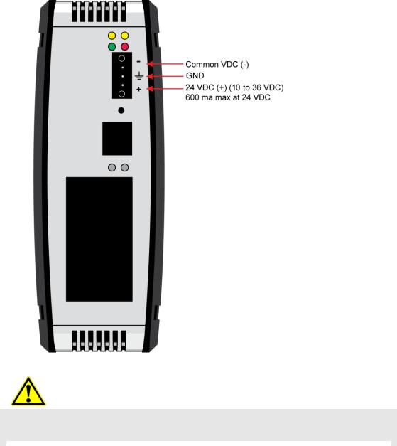
1.6Connecting Power to the PLX3x Gateway
WARNING: Ensure that polarity is not reversed when applying power to the gateway. This will cause damage to the gateway’s power supply.
|
|
|
|
|
|
|
|
ProSoft Technology, Inc. |
Page 13 of 218 |
||
September 17, 2014 |
|
|
|

|
PLX3x Series |
User Manual |
Ethernet and Serial Gateways |
|
|
Page 14 of 218 |
ProSoft Technology, Inc. |
|
September 17, 2014 |

PLX3x Series |
Configuring Your Gateway |
Ethernet and Serial Gateways |
User Manual |
|
|
2 Configuring Your Gateway
In This Chapter |
|
|
Installing ProSoft Configuration Builder Software ............................. |
16 |
|
Using the Online Help....................................................................... |
17 |
|
Setting Up the Project....................................................................... |
17 |
|
|
Renaming PCB Objects.................................................................... |
20 |
|
Configuring the Drivers ..................................................................... |
21 |
Using the CommonNet Data Map ..................................................... |
25 |
|
Configuring an IP Addres.................................................................. |
27 |
|
Downloading the Project to the Gateway.......................................... |
29 |
|
Printing a Configuration FIle ............................................................. |
31 |
|
ProSoft Configuration Builder (PCB) is a convenient and powerful software tool for managing your gateway configuration. Use PCB to configure a new project, or to transfer an existing project to a new device. You can also to use PCB to retrieve a configuration from a working gateway by uploading the configuration from the gateway.
ProSoft Technology, Inc. |
Page 15 of 218 |
September 17, 2014 |
|
Configuring Your Gateway |
PLX3x Series |
User Manual |
Ethernet and Serial Gateways |
|
|
2.1Installing ProSoft Configuration Builder Software
You must install the ProSoft Configuration Builder (PCB) software to configure the gateway. You can always get the newest version of ProSoft Configuration Builder from the ProSoft Technology website.
To install ProSoft Configuration Builder from the ProSoft Technology website
1Open your web browser and navigate to http://www.prosofttechnology.com/pcb
2Click the link at the Current Release Version section to download the latest version of ProSoft Configuration Builder.
3Choose SAVE or SAVE FILE when prompted.
4Save the file to your Windows Desktop, so that you can find it easily when you have finished downloading.
5When the download is complete, locate and open the file, and then follow the instructions on your screen to install the program.
If you do not have access to the Internet, you can install ProSoft Configuration Builder from the ProSoft Solutions DVD, included in the package with your gateway.
To Install ProSoft Configuration Builder from the DVD
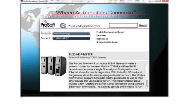
1Insert the ProSoft Solutions DVD into the DVD drive of your PC. Wait for the DVD menu to appear.
2On the startup screen, navigate to your product by selecting the proper
PLATFORM and PRODUCT.
3Select PROSOFT CONFIGURAITON BUILDER. Follow the instructions on your screen to install the software on your PC.
Page 16 of 218 |
ProSoft Technology, Inc. |
|
September 17, 2014 |
PLX3x Series |
Configuring Your Gateway |
Ethernet and Serial Gateways |
User Manual |
|
|
2.2Using the Online Help
Most of the information needed to help you use ProSoft Configuration Builder is provided in a Help System that is always available whenever you are running ProSoft Configuration Builder. The Help System does not require an Internet connection.
To view the help pages, start ProSoft Configuration Builder, open the HELP menu, and then choose CONTENTS.
2.3Setting Up the Project
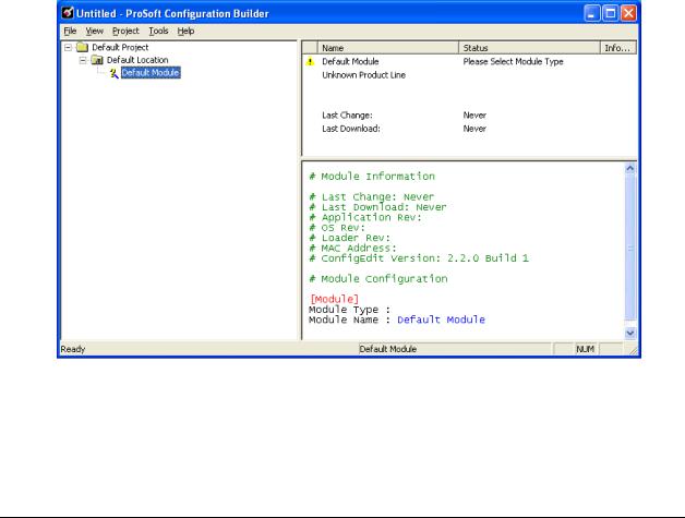
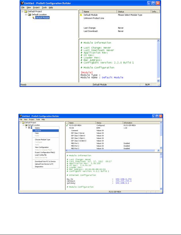
To begin, start ProSoft Configuration Builder (PCB). If you have used other Windows configuration tools before, you will find the screen layout familiar.
ProSoft Configuration Builder’s (PCB's) window consists of a tree view on the left, and an information pane on the upper right side, and a configuration pane on the lower right side of the window. When you first start PCB, the tree view consists of folders for Default Project and Default Location, with a Default Gateway in the Default Location folder. The following screen shows the PCB window with a new project.
ProSoft Technology, Inc. |
Page 17 of 218 |
September 17, 2014 |
|

Configuring Your Gateway |
PLX3x Series |
User Manual |
Ethernet and Serial Gateways |
|
|
To add the gateway to the project
1Use the mouse to select DEFAULT MODULE in the tree view, and then click the right mouse button to open a shortcut menu.
Page 18 of 218 |
ProSoft Technology, Inc. |
|
September 17, 2014 |
PLX3x Series |
Configuring Your Gateway |
Ethernet and Serial Gateways |
User Manual |
|
|
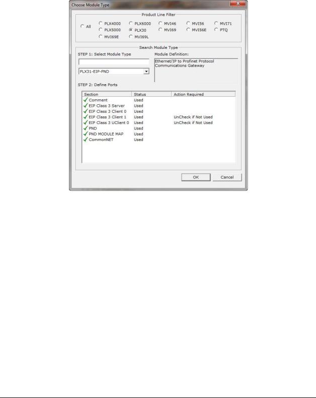
2On the shortcut menu, select CHOOSE MODULE TYPE. This action opens the Choose Module Type dialog box.
3In the Product Line Filter area of the dialog box, select the PLX30 radio button.
4In the STEP 1: Select Module Type drop-down list, select the model number that matches your gateway, and then click OK to save your settings and return to the PCB Main window.
ProSoft Technology, Inc. |
Page 19 of 218 |
September 17, 2014 |
|
Configuring Your Gateway |
PLX3x Series |
User Manual |
Ethernet and Serial Gateways |
|
|
2.4Renaming PCB Objects
The Default Project and Default Location folders may be renamed in the tree view. Select the object, and then click the right mouse button to open a shortcut menu. From the shortcut menu, choose RENAME.
1Type the name to assign to the object.
2Click away from the object to save the new name.
Page 20 of 218 |
ProSoft Technology, Inc. |
|
September 17, 2014 |
PLX3x Series |
Configuring Your Gateway |
Ethernet and Serial Gateways |
User Manual |
|
|
2.5Configuring the Drivers
1 Click the [+] sign next to the Gateway icon to expand gateway information. 2 Click the [+] sign next to any  icon to view gateway information and
configuration options.
3Double-click any  icon to open an Edit dialog box.
4To edit a parameter, select the parameter name in the left hand pane, then edit its corresponding field in the right hand pane.
Note: Depending on the parameter, the editable field will accept typed input in the form of text or a valid numerical value, or it will have a dropdown list with options to choose from.
|
|
|
|
|
|
|
|
ProSoft Technology, Inc. |
Page 21 of 218 |
||
September 17, 2014 |
|
|
|

Configuring Your Gateway |
PLX3x Series |
User Manual |
Ethernet and Serial Gateways |
|
|
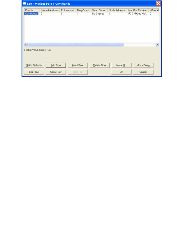
5 Double-clicking any  icon will open an Edit dialog box with a table.
6 To add a row to the table, click the Add Row button.
Page 22 of 218 |
ProSoft Technology, Inc. |
|
September 17, 2014 |
PLX3x Series |
Configuring Your Gateway |
Ethernet and Serial Gateways |
User Manual |
|
|
ProSoft Technology, Inc. |
Page 23 of 218 |
September 17, 2014 |
|
Configuring Your Gateway |
PLX3x Series |
User Manual |
Ethernet and Serial Gateways |
|
|
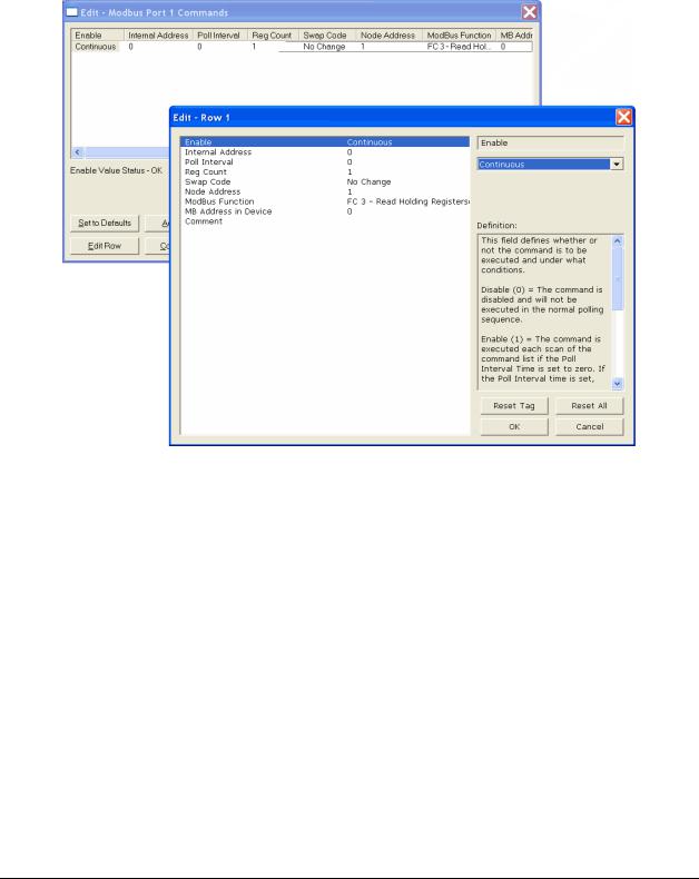
7To edit the row, click the Edit Row button. This will open an Edit dialog box where you can edit the row parameters.
8When configuration is complete, download the configuration to the gateway.
9For protocol-specific configuration information, see the Configuration section in the appropriate protocol chapter of this manual:
EIP configuration (page 54) MBTCP configuration (page 98) MBS configuration(page125) ASCII configuration (page 161) SIE configuration (page 167) PND configuration (page 194)
Page 24 of 218 |
ProSoft Technology, Inc. |
|
September 17, 2014 |

PLX3x Series |
Configuring Your Gateway |
Ethernet and Serial Gateways |
User Manual |
|
|
2.6Using the CommonNet Data Map
Note: This is an advanced configuration feature and is not required for the basic operation of the gateway.
The Data Map section allows data to be copied between areas in the gateway's internal database.
The Data Map is especially useful for copying protocol-specific error and status data from the gateway’s upper memory registers (address 4000 and up) to the user-accessible memory registers (addresses 0 to 3999). The error and status data copied into the user memory area can then be accessed by a remote device, such as an HMI or processor.
Information about upper memory addresses where the gateway places protocolspecific error and status data can be found in the Diagnostics section in the appropriate protocol chapter of this manual:
EIP diagnostics (page 70)
MBTCP diagnostics (page 105)
MBS diagnostics (page 132)
ASCII diagnostics (page 163)
SIE diagnostics (page 181)
PND diagnostics (page 213)
The Data Map can also be used to condense widely dispersed data into one contiguous data block, for simplified access.
A maximum of 100 registers per Data Map command can be copied, and a maximum of 200 separate copy commands can be configured.
The byte and/or word order can be rearranged during the copy process. For example, by rearranging byte or word order, floating-point values can be converted to the correct format for a different protocol.
ProSoft Technology, Inc. |
Page 25 of 218 |
September 17, 2014 |
|

Configuring Your Gateway |
PLX3x Series |
User Manual |
Ethernet and Serial Gateways |
|
|
The following illustration shows an example Data Map.
The following table describes the parameters for configuring the Data Map.
Parameter |
Value |
Description |
From Address |
0 to highest |
This parameter specifies the beginning internal database |
|
Status Data |
register address for the copy operation. This address can be |
|
address |
any valid address in the User Data Area or the Status Data |
|
|
Area of the gateway. |
|
|
|
To Address |
0 to 3999 |
This parameter specifies the beginning destination register |
|
|
address for the copy operation. This address must always be |
|
|
within the User Data registers area. A destination address |
|
|
must be specified that will not overwrite data that has been |
|
|
stored in memory by one of the communication protocols |
|
|
running on the gateway. |
|
|
|
Register Count |
1 to 100 |
This parameter specifies the number of registers to copy. |
Swap Code |
No Change |
The order of the bytes in the registers may need to be |
|
Word Swap |
swapped during the copy process in order to change the |
|
Word and Byte |
alignment of bytes between dissimilar protocols. This |
|
Swap |
parameter is helpful when dealing with floating-point or other |
|
Byte Swap |
multi-register values, as there is no standard method of |
|
|
storage of these data types in slave devices. |
|
|
No change: No change is made in the byte ordering (1234 = |
|
|
1234) |
|
|
Word Swap: The words are swapped (1234=3412) |
|
|
Word and Byte Swap: The words are swapped, then the |
|
|
bytes in each word are swapped (1234=4321) |
|
|
Byte Swap: The bytes in each word are swapped |
|
|
(1234=2143) |
Delay Preset |
|
This parameter sets an interval for each Data Map copy |
|
|
operation. The value that is specified for the Delay Preset is |
|
|
not a fixed amount of time. It is the number of firmware scans |
|
|
that must transpire between copy operations. |
|
|
|
Page 26 of 218 |
ProSoft Technology, Inc. |
|
September 17, 2014 |
PLX3x Series |
Configuring Your Gateway |
Ethernet and Serial Gateways |
User Manual |
|
|
2.7Configuring an IP Address
Use this procedure to configure the Ethernet settings for your Gateway. You must assign an IP address, subnet mask and gateway address. After you complete this step, you can connect to the Gateway with an Ethernet cable.
Note: The PLX32 module contains two Ethernet ports. In this case, you would specify network settings for the first Ethernet protocol on Enet P1 and another set of settings for the second Ethernet Protocol on Enet P2.
1Determine the network settings for your Gateway, with the help of your network administrator if necessary. You will need the following information:
o IP address (fixed IP required) _____ . _____ . _____ . _____
o |
Subnet mask |
_____ . _____ . _____ . _____ |
o |
Gateway address |
_____ . _____ . _____ . _____ |
|
|
|
|
|
|
Note: The gateway address is optional, and is not required for networks that do not use a default gateway.
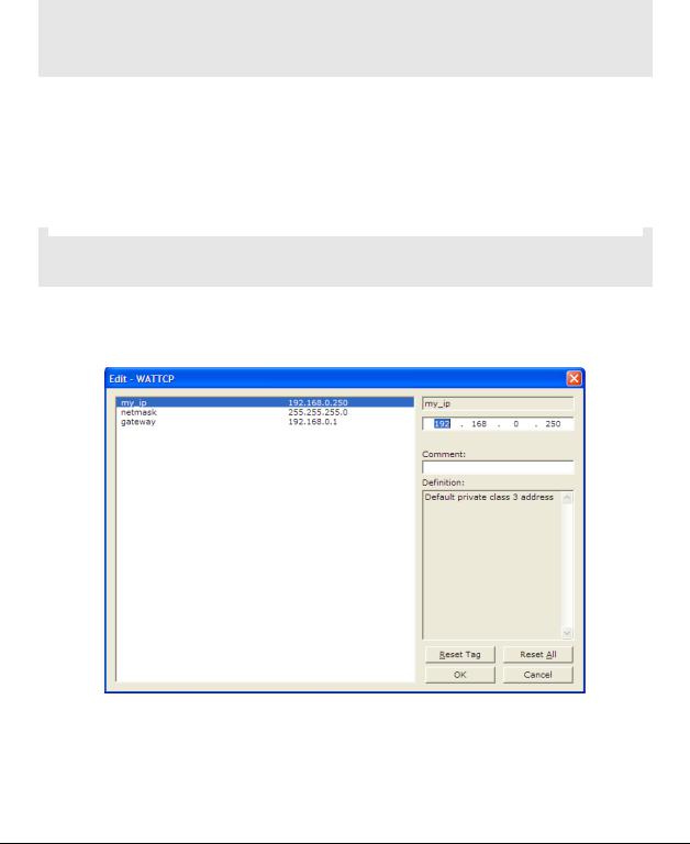
2Double-click the ETHERNET CONFIGURATION icon. This action opens the Edit dialog box. The IP address shown is the gateway default IP address.
3Edit the values for my_ip, netmask (subnet mask) and gateway (default gateway).
ProSoft Technology, Inc. |
Page 27 of 218 |
September 17, 2014 |
|

Configuring Your Gateway |
PLX3x Series |
||
User Manual |
Ethernet and Serial Gateways |
||
|
|
|
|
|
|
|
|
|
|
|
|
Note: If you are using a PLX32 module, you must specify values for both ports. My_ip is used to specify values for the first protocol. For example, if you are configuring a PLX32-EIP-PND, you would specify the network values for the EIP protocol first. A second set of values are available for the second protocol; in this case, PND.
4When you are finished editing, click OK to save your changes and return to the ProSoft Configuration Builder window.
Page 28 of 218 |
ProSoft Technology, Inc. |
|
September 17, 2014 |

PLX3x Series |
Configuring Your Gateway |
Ethernet and Serial Gateways |
User Manual |
|
|
2.8Downloading the Project to the Gateway
For the gateway to use the settings you configured, you must download (copy) the updated Project file from your PC to the gateway.
To download the project file
1In the tree view in ProSoft Configuration Builder, click once to select the gateway.
2Right-click the Gateway icon to open a shortcut menu. From the shortcut menu, choose DOWNLOAD FROM PC TO DEVICE.
3Click the BROWSE DEVICE(S) button to launch the ProSoft Discovery Service window, which displays the ProSoft devices on the network and their IP addresses.
ProSoft Technology, Inc. |
Page 29 of 218 |
September 17, 2014 |
|
Configuring Your Gateway |
PLX3x Series |
User Manual |
Ethernet and Serial Gateways |
|
|
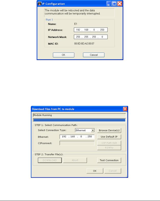
4Right-click your PLX3x-series gateway and select IP Configuration from the shortcut menu.
5Enter the same IP address and network mask that you entered in the Ethernet configuration of the gateway. Click OK. The gateway will reboot.
6Close the ProSoft Discovery Service window to return to the Download dialog box.
7Click the DOWNLOAD button.
The gateway will perform a platform check to read and load its new settings. When the platform check is complete, the status bar in the Download dialog box will display the message Module Running.
Page 30 of 218 |
ProSoft Technology, Inc. |
|
September 17, 2014 |
 Loading...