


 Loading...
PTQ-104S Rev 1
Quantum Platform
IEC 60870-5-104 Server for
Quantum
March 4, 2013
USER MANUAL
Your Feedback Please
We always want you to feel that you made the right decision to use our products. If you have suggestions, comments, compliments or complaints about our products, documentation, or support, please write or call us.
ProSoft Technology
5201 Truxtun Ave., 3rd Floor Bakersfield, CA 93309
+1 (661) 716-5100
+1 (661) 716-5101 (Fax) www.prosoft-technology.com support@prosoft-technology.com
Copyright © 2013 ProSoft Technology, Inc., All rights reserved.
PTQ-104S Rev1 User Manual
March 4, 2013
ProSoft Technology ®, ProLinx ®, inRAx ®, ProTalk®, and RadioLinx ® are Registered Trademarks of ProSoft Technology, Inc. All other brand or product names are or may be trademarks of, and are used to identify products and services of, their respective owners.
In an effort to conserve paper, ProSoft Technology no longer includes printed manuals with our product shipments. User Manuals, Datasheets, Sample Ladder Files, and Configuration Files are provided on the enclosed DVD, and are available at no charge from our web site: http://www.prosoft-technology.com
Content Disclaimer
This documentation is not intended as a substitute for and is not to be used for determining suitability or reliability of these products for specific user applications. It is the duty of any such user or integrator to perform the appropriate and complete risk analysis, evaluation and testing of the products with respect to the relevant specific application or use thereof. Neither ProSoft Technology nor any of its affiliates or subsidiaries shall be responsible or liable for misuse of the information contained herein. Information in this document including illustrations, specifications and dimensions may contain technical inaccuracies or typographical errors. ProSoft Technology makes no warranty or representation as to its accuracy and assumes no liability for and reserves the right to correct such inaccuracies or errors at any time without notice. If you have any suggestions for improvements or amendments or have found errors in this publication, please notify us.
No part of this document may be reproduced in any form or by any means, electronic or mechanical, including photocopying, without express written permission of ProSoft Technology. All pertinent state, regional, and local safety regulations must be observed when installing and using this product. For reasons of safety and to help ensure compliance with documented system data, only the manufacturer should perform repairs to components. When devices are used for applications with technical safety requirements, the relevant instructions must be followed. Failure to use ProSoft Technology software or approved software with our hardware products may result in injury, harm, or improper operating results. Failure to observe this information can result in injury or equipment damage.
© 2013 ProSoft Technology. All rights reserved.
Printed documentation is available for purchase. Contact ProSoft Technology for pricing and availability. North America: +1.661.716.5100
Asia Pacific: +603.7724.2080
Europe, Middle East, Africa: +33 (0) 5.3436.87.20 Latin America: +1.281.298.9109
Information for ProTalk® Product Users
The statement "power, input and output (I/O) wiring must be in accordance with Class I, Division 2 wiring methods Article 501-10(b) of the National Electrical Code, NFPA 70 for installations in the U.S., or as specified in section 181J2 of the Canadian Electrical Code for installations within Canada and in accordance with the authority having jurisdiction".
The following or equivalent warnings shall be included:
AWarning - Explosion Hazard - Substitution of components may Impair Suitability for Class I, Division 2;
BWarning - Explosion Hazard - When in Hazardous Locations, Turn off Power before replacing Wiring Modules, and
CWarning - Explosion Hazard - Do not Disconnect Equipment unless Power has been switched Off or the Area is known to be Nonhazardous.
DCaution: The Cell used in this Device may Present a Fire or Chemical Burn Hazard if Mistreated. Do not Disassemble, Heat above 100°C (212°F) or Incinerate.
WARNING - EXPLOSION HAZARD - DO NOT DISCONNECT EQUIPMENT UNLESS POWER HAS BEEN SWITCHED OFF OR THE AREA IS KNOWN TO BE NON-HAZARDOUS.
AVERTISSEMENT - RISQUE D'EXPLOSION - AVANT DE DÉCONNECTER L'ÉQUIPEMENT, COUPER LE COURANT OU S'ASSURER QUE L'EMPLACEMENT EST DÉSIGNÉ NON DANGEREUX.
Class I, Division 2 GPs A, B, C, D II 3 G
Ex nA IIC X
0° C <= Ta <= 60° C
II - Equipment intended for above ground use (not for use in mines). 3 - Category 3 equipment, investigated for normal operation only. G - Equipment protected against explosive gasses.
Warnings
North America Warnings
AWarning - Explosion Hazard - Substitution of components may impair suitability for Class I, Division 2.
BWarning - Explosion Hazard - When in hazardous locations, turn off power before replacing or rewiring modules. Warning - Explosion Hazard - Do not disconnect equipment unless power has been switched off or the area is known to be non-hazardous.
CSuitable for use in Class I, Division 2 Groups A, B, C and D Hazardous Locations or Non-Hazardous Locations.
ATEX Warnings and Conditions of Safe Usage:
Power, Input, and Output (I/O) wiring must be in accordance with the authority having jurisdiction.
AWarning - Explosion Hazard - When in hazardous locations, turn off power before replacing or wiring modules.
BWarning - Explosion Hazard - Do not disconnect equipment unless power has been switched off or the area is known to be non-hazardous.
CThese products are intended to be mounted in an IP54 enclosure. The devices shall provide external means to prevent the rated voltage being exceeded by transient disturbances of more than 40%. This device must be used only with ATEX certified backplanes.
DDO NOT OPEN WHEN ENERGIZED.
Electrical Ratings
Backplane Current Load: 1100 mA maximum @ 5 Vdc ± 5%
Operating Temperature: 0°C to 60°C (32°F to 140°F)
Storage Temperature: -40°C to 85°C (-40°F to 185°F)
Shock: 30 g operational; 50 g non-operational; Vibration: 5 g from 10 to 150 Hz
Relative Humidity: 5% to 95% (without condensation)
All phase conductor sizes must be at least 1.3 mm(squared) and all earth ground conductors must be at least 4mm(squared).

Markings:
CSA/cUL
CSA CB Certified
ATEX
Important Notice:
CAUTION: THE CELL USED IN THIS DEVICE MAY PRESENT A FIRE
OR CHEMICAL BURN HAZARD IF MISTREATED. DO NOT
DISASSEMBLE, HEAT ABOVE 100°C (212°F) OR INCINERATE.
Maximum battery load = 200 μA.
Maximum battery charge voltage = 3.4 VDC.
Maximum battery charge current = 500 μA.
Maximum battery discharge current = 30 μA.
48TPTQ-104S Rev 1 |
♦47TQuantum Platform |
Contents |
46TIEC 60870-5-104 |
Server for Quantum |
12TUser Manual |
|
|
|
Contents
|
|
Your Feedback Please........................................................................................................................ |
2 |
||
|
|
Information for ProTalk® Product Users.............................................................................................. |
3 |
||
|
|
Warnings ............................................................................................................................................. |
|
3 |
|
|
|
Important Notice:................................................................................................................................. |
4 |
||
|
Guide to the PTQ-104S User Manual |
9 |
|||
|
|
|
|
|
|
|
1 |
Start Here |
|
11 |
|
|
|
|
|
|
|
|
|
1.1 |
Hardware and Software Requirements ................................................................... |
12 |
|
|
|
1.1.1 |
Package Contents ................................................................................................... |
12 |
|
|
|
1.1.2 |
Quantum Hardware ................................................................................................. |
12 |
|
|
|
1.1.3 |
PC and Software ..................................................................................................... |
13 |
|
|
|
1.2 |
Install ProSoft Configuration Builder Software........................................................ |
13 |
|
|
|
1.3 |
Setting Up the ProTalk Module ............................................................................... |
14 |
|
|
|
1.3.1 |
Install the ProTalk Module in the Quantum Rack.................................................... |
14 |
|
|
|
1.3.2 |
Connect the PC to the ProTalk Configuration/Debug Port...................................... |
16 |
|
|
|
1.3.3 |
Ethernet Configuration ............................................................................................ |
18 |
|
|
2 |
Configuring the Processor with Unity Pro |
21 |
||
|
|
|
|
|
|
|
|
2.1 |
Create a New Project .............................................................................................. |
22 |
|
|
|
2.2 |
Add the PTQ Module to the Project ........................................................................ |
24 |
|
|
|
2.3 |
Build the Project ...................................................................................................... |
25 |
|
|
|
2.4 |
Connect Your PC to the Processor ......................................................................... |
26 |
|
|
|
2.4.1 |
Connecting to the Processor with TCP/IP............................................................... |
28 |
|
|
|
2.5 |
Download the Project to the Processor................................................................... |
28 |
|
|
3 |
Configuring the Processor with Concept |
31 |
||
|
|
|
|
|
|
|
|
3.1 |
Information for Concept Version 2.6 Users ............................................................. |
32 |
|
|
|
3.1.1 |
Installing MDC Configuration Files.......................................................................... |
32 |
|
|
|
3.2 |
Creating a New Project ........................................................................................... |
33 |
|
|
|
3.3 |
Adding the PTQ Module to the Project.................................................................... |
36 |
|
|
|
3.4 |
Setting the Time of Day........................................................................................... |
39 |
|
|
|
3.5 |
Saving the Project ................................................................................................... |
40 |
|
|
|
3.6 |
Downloading the Project to the Processor .............................................................. |
42 |
|
4 |
Configuring the Processor with ProWORX |
45 |
|||
|
|
|
|
|
|
|
5 |
Module Configuration |
49 |
||
|
|
|
|
|
|
|
|
5.1 |
Using ProSoft Configuration Builder ....................................................................... |
50 |
|
|
|
5.1.1 |
Setting Up the Project ............................................................................................. |
50 |
|
|
|
5.1.2 |
Set Module Parameters........................................................................................... |
53 |
|
|
|
5.2 |
[Backplane Configuration] ....................................................................................... |
54 |
|
|
|
5.2.1 |
Module Name .......................................................................................................... |
54 |
|
|
|
|
|||
ProSoft Technology, Inc. |
|
Page 5 of 201 |
|||
March 4, 2013 |
|
|
|
||

Contents |
48TPTQ-104S Rev 1 ♦47TQuantum Platform |
|
12TUser Manual |
46TIEC 60870-5-104 Server for Quantum |
|
5.2.2 |
Failure Flag Count .................................................................................................. |
54 |
5.2.3 |
Error Offset ............................................................................................................. |
55 |
5.2.4 |
Initialize Output Data .............................................................................................. |
55 |
5.3 |
Backplane Data Exchange ..................................................................................... |
55 |
5.3.1 |
Data Transfer.......................................................................................................... |
55 |
5.3.2 |
Defining Data to be Sent to the PTQ Database...................................................... |
56 |
5.3.3 |
Defining Data to be Retrieved from the PTQ Database. ........................................ |
58 |
5.3.4 |
Defining Special Functions ..................................................................................... |
59 |
5.3.5 |
Implementing Ladder to Support Special Functions............................................... |
62 |
5.4 |
Modify the [Backplane Data Exchange] Section..................................................... |
63 |
5.4.1 |
Set Up Command Function 1 (Read data from the Quantum) ............................... |
64 |
5.4.2 |
Set Up Command Function 2 (Write data to the Quantum) ................................... |
66 |
5.4.3 |
Set Up Command Function 3 (Special Functions) ................................................. |
68 |
5.4.4 |
Read Status (9250)................................................................................................. |
69 |
5.4.5 |
Event Messages (9958).......................................................................................... |
71 |
5.4.6 |
Read Module's Time to Processor (9970) .............................................................. |
72 |
5.4.7 |
Block 9971: Set Module Time................................................................................. |
73 |
5.4.8 |
Block 9998 or 9999: Reboot Module ...................................................................... |
74 |
5.5 |
[SNTP CLIENT]....................................................................................................... |
74 |
5.5.1 |
NTP Server IP Address .......................................................................................... |
75 |
5.5.2 |
Time Zone............................................................................................................... |
75 |
5.5.3 |
Use Daylight Savings Time..................................................................................... |
76 |
5.5.4 |
Database Register .................................................................................................. |
76 |
5.6 |
[IEC-870-5-104] ...................................................................................................... |
76 |
5.6.1 |
Use IP List............................................................................................................... |
77 |
5.6.2 |
Override StartDT..................................................................................................... |
77 |
5.6.3 |
Clear Queue on Close ............................................................................................ |
77 |
5.6.4 |
t0 Connection Timeout............................................................................................ |
77 |
5.6.5 |
t1 Timeout Set Value .............................................................................................. |
77 |
5.6.6 |
t2 Timeout Set Value .............................................................................................. |
78 |
5.6.7 |
t3 Timeout Set Value .............................................................................................. |
78 |
5.6.8 |
k (maximum queue) ................................................................................................ |
78 |
5.6.9 |
w (latest ack threshold)........................................................................................... |
78 |
5.6.10 |
Time DB Offset ....................................................................................................... |
78 |
5.6.11 |
Error Offset ............................................................................................................. |
79 |
5.6.12 |
Command Delay Timer........................................................................................... |
79 |
5.6.13 |
Maximum ASDU Resp Len..................................................................................... |
79 |
5.6.14 |
Freeze Start Type ................................................................................................... |
79 |
5.6.15 |
Interval for Freeze................................................................................................... |
79 |
5.6.16 |
Common Address of ASDU .................................................................................... |
80 |
5.6.17 |
Cyclic Data Transmission ....................................................................................... |
80 |
5.6.18 |
Select/Operate Timeout.......................................................................................... |
80 |
5.6.19 |
Use ACTTERM with Setpoint ................................................................................. |
80 |
5.6.20 |
Use ACTTERM with step........................................................................................ |
80 |
5.6.21 |
Event Scan Delay ................................................................................................... |
80 |
5.6.22 |
Set Priority Queues................................................................................................. |
81 |
5.6.23 |
Cyclic Set IV Time .................................................................................................. |
82 |
5.6.24 |
IV Check Delay Time .............................................................................................. |
83 |
5.6.25 |
IV Fail Count ........................................................................................................... |
83 |
5.6.26 |
Scan Events............................................................................................................ |
84 |
5.6.27 |
Time Type ............................................................................................................... |
85 |
5.6.28 |
Use Recent ............................................................................................................. |
86 |
5.7 |
IEC 60870-5-104 Server section ............................................................................ |
87 |
5.8 |
[IEC-870-5-104 Database]...................................................................................... |
88 |
Page 6 of 201 |
ProSoft Technology, Inc. |
|
|
|
March 4, 2013 |
48TPTQ-104S Rev 1 ♦47TQuantum Platform |
Contents |
||||
46TIEC 60870-5-104 Server for Quantum |
12TUser Manual |
||||
|
|
|
|
|
|
|
|
5.8.1 |
Short Pulse Time..................................................................................................... |
88 |
|
|
|
5.8.2 |
Long Pulse Time ..................................................................................................... |
88 |
|
|
|
5.8.3 |
Default Command Qualifier ..................................................................................... |
89 |
|
|
|
5.8.4 |
Override Command Qualifier .................................................................................. |
89 |
|
|
|
5.8.5 |
Point Count.............................................................................................................. |
89 |
|
|
|
5.8.6 |
Sequence Flag ........................................................................................................ |
90 |
|
|
|
5.8.7 |
Parameter Offset ..................................................................................................... |
91 |
|
|
|
5.9 |
[IEC-870-5-104 IP Addresses] ................................................................................ |
92 |
|
|
|
5.10 |
[M_SP_NA_1 104]................................................................................................... |
92 |
|
|
|
5.11 |
[M_DP_NA_1 104] .................................................................................................. |
93 |
|
|
|
5.12 |
[M_ST_NA_1 104]................................................................................................... |
93 |
|
|
|
5.13 |
[M_BO_NA_1 104] .................................................................................................. |
93 |
|
|
|
5.14 |
[M_ME_NA_1 104] .................................................................................................. |
94 |
|
|
|
5.15 |
[M_ME_NB_1 104] .................................................................................................. |
94 |
|
|
|
5.16 |
[M_ME_NC_1 104].................................................................................................. |
94 |
|
|
|
5.17 |
[M_IT_NA_1 104] .................................................................................................... |
95 |
|
|
|
5.18 |
[C_SC_NA_1 104]................................................................................................... |
95 |
|
|
|
5.19 |
[C_DC_NA_1 104]................................................................................................... |
96 |
|
|
|
5.20 |
[C_RC_NA_1 104]................................................................................................... |
96 |
|
|
|
5.21 |
[C_BO_NA_1 104]................................................................................................... |
96 |
|
|
|
5.22 |
[C_SE_NA_1 104] ................................................................................................... |
97 |
|
|
|
5.23 |
[C_SE_NB_1 104] ................................................................................................... |
97 |
|
|
|
5.24 |
[C_SE_NC_1 104]................................................................................................... |
98 |
|
|
|
5.25 |
Group Codes ........................................................................................................... |
98 |
|
|
|
5.26 |
CommonNet Data Map............................................................................................ |
99 |
|
|
|
5.26.1 |
From Address........................................................................................................ |
100 |
|
|
|
5.26.2 |
To Address ............................................................................................................ |
100 |
|
|
|
5.26.3 |
Register Count ...................................................................................................... |
101 |
|
|
|
5.26.4 |
Swap Code............................................................................................................ |
101 |
|
|
|
5.26.5 |
Delay Preset.......................................................................................................... |
101 |
|
|
|
5.27 |
To Create Optional Comment Entries ................................................................... |
102 |
|
|
|
5.28 |
To Print a Configuration File.................................................................................. |
102 |
|
|
6 |
Downloading the Project to the Module |
105 |
||
|
|
|
|
|
|
|
|
6.1 |
Downloading via Serial Connection ...................................................................... |
105 |
|
7 |
Hot Standby Support |
109 |
|||
|
|
|
|
|
|
|
8 |
Diagnostics and Troubleshooting |
111 |
||
|
|
|
|
|
|
|
|
8.1 |
The Configuration/Debug Menu ............................................................................ |
112 |
|
|
|
8.1.1 |
Required Hardware ............................................................................................... |
112 |
|
|
|
8.1.2 |
Using the Diagnostic Window in ProSoft Configuration Builder............................ |
112 |
|
|
|
8.1.3 |
Navigation ............................................................................................................. |
114 |
|
|
|
8.1.4 |
IEC-870-5-104 Server Menu ................................................................................. |
117 |
|
|
|
8.1.5 |
Main Menu............................................................................................................. |
120 |
|
|
|
8.1.6 |
Database View Menu ............................................................................................ |
123 |
|
|
|
8.1.7 |
Network Menu ....................................................................................................... |
125 |
|
|
|
8.2 |
LED Indicators....................................................................................................... |
126 |
|
|
|
8.2.1 |
Ethernet LED Indicators ........................................................................................ |
126 |
|
|
|
8.2.2 |
Error Status Table ................................................................................................. |
126 |
|
|
|
|
|||
ProSoft Technology, Inc. |
|
Page 7 of 201 |
|||
March 4, 2013 |
|
|
|
||

Contents |
|
48TPTQ-104S Rev 1 ♦47TQuantum Platform |
|||
12TUser Manual |
46TIEC 60870-5-104 Server for Quantum |
||||
|
|
|
|
|
|
|
9 |
Reference |
|
127 |
|
|
|
|
|
|
|
|
|
9.1 |
Product Specifications .......................................................................................... |
128 |
|
|
|
9.1.1 |
Standards.............................................................................................................. |
128 |
|
|
|
9.1.2 |
General Specifications.......................................................................................... |
128 |
|
|
|
9.1.3 |
Hardware Specifications ....................................................................................... |
129 |
|
|
|
9.1.4 |
Functional Specifications ...................................................................................... |
129 |
|
|
|
9.2 |
PTQ-104S Protocol Implementation..................................................................... |
131 |
|
|
|
9.2.1 |
Module Address.................................................................................................... |
131 |
|
|
|
9.2.2 |
Monitor Direction and Control Direction: Point Definition ..................................... |
134 |
|
|
|
9.2.3 |
Using Monitor Points............................................................................................. |
136 |
|
|
|
9.2.4 |
Using Control (Command) Points ......................................................................... |
148 |
|
|
|
9.2.5 |
Data Communication ............................................................................................ |
154 |
|
|
|
9.2.6 |
Events ................................................................................................................... |
161 |
|
|
|
9.2.7 |
Sequence Flag...................................................................................................... |
173 |
|
|
|
9.3 |
Cable Connections ............................................................................................... |
174 |
|
|
|
9.3.1 |
Ethernet Connection ............................................................................................. |
175 |
|
|
|
9.3.2 |
RS-232 Configuration/Debug Port........................................................................ |
175 |
|
|
|
9.4 |
Error Status Table................................................................................................. |
176 |
|
|
|
9.5 |
Group Codes......................................................................................................... |
179 |
|
|
|
9.6 |
IEC 60870-5-104 Server Interoperability Statement............................................. |
180 |
|
|
|
9.6.1 |
System or device .................................................................................................. |
180 |
|
|
|
9.6.2 |
Application Layer .................................................................................................. |
180 |
|
|
|
9.6.3 |
Selection of standard ASDUs ............................................................................... |
181 |
|
|
|
9.6.4 |
Type identifier and cause of transmission assignments....................................... |
184 |
|
|
|
9.6.5 |
Basic Application Functions.................................................................................. |
186 |
|
|
|
9.7 |
PTQ-104S Database Design Forms..................................................................... |
191 |
|
|
|
9.7.1 |
M_SP_NA_1, M_DP_NA_1, M_ST_NA_1 and M_IT_NA_1 Form ...................... |
191 |
|
|
|
9.7.2 |
M_ME_NA_1 and M_ME_NB_1 Form ................................................................. |
192 |
|
|
|
9.7.3 |
Form for All C_ (Command) Data Types, Except C_RC_NA_1 ........................... |
193 |
|
|
|
9.7.4 |
C_RC_NA_1 Form................................................................................................ |
194 |
|
|
|
9.8 |
Frequently Asked Questions................................................................................. |
195 |
|
|
|
9.8.1 |
How fast do the "Backplane Data Exchange" commands run?............................ |
195 |
|
9.8.2What is the maximum number of words I can transfer with a "Backplane Data
Exchange" command? .............................................................................................................. |
195 |
|
9.8.3 |
How do I configure the module?........................................................................... |
195 |
9.8.4What kind of data transfer rates can I expect between the PLC and the module?195
9.8.5 |
Is a .MDC available for configuration of the Module?........................................... |
195 |
9.8.6 |
Does the module work in a remote rack? ............................................................. |
195 |
9.8.7 |
Can I use the module in a hot backup system?.................................................... |
195 |
10 Support, Service & Warranty |
197 |
|
Contacting Technical Support ........................................................................................................ |
197 |
|
10.1 |
Warranty Information ............................................................................................ |
198 |
Index |
|
199 |
Page 8 of 201 |
ProSoft Technology, Inc. |
|
March 4, 2013 |

48TPTQ-104S Rev 1 |
♦47TQuantum Platform |
Start Here |
46TIEC 60870-5-104 |
Server for Quantum |
12TUser Manual |
|
|
|
Guide to the PTQ-104S User Manual
Function
Introduction
(Must Do)
Diagnostic and
Troubleshooting
|
Section to Read |
Details |
|
|
|
→ |
Start Here (page 11) |
This section introduces the customer to the |
|
|
module. Included are: package contents, |
|
|
system requirements, hardware installation, and |
|
|
basic configuration. |
|
|
|
|
|
|
→ |
Diagnostics and |
This section describes Diagnostic and |
|
Troubleshooting |
Troubleshooting procedures. |
|
(page 111) |
|
|
|
|
Reference
Product Specifications
Functional
Specifications
Support, Service, and
Warranty
Index
→Reference (page 127)
Product Specifications (page 128)
Functional Specifications (page 129)
These sections contain general references associated with this product, Specifications, and the Functional Overview.
→ |
Support, Service |
This section contains Support, Service and |
|
and Warranty (page |
Warranty information. |
|
197) |
|
|
Index |
Index of chapters. |
ProSoft Technology, Inc. |
Page 9 of 201 |
March 4, 2013 |
|
Start Here |
48TPTQ-104S Rev 1 ♦47TQuantum Platform |
12TUser Manual |
46TIEC 60870-5-104 Server for Quantum |
|
|
Page 10 of 201 |
ProSoft Technology, Inc. |
|
March 4, 2013 |
48TPTQ-104S Rev 1 |
♦47TQuantum Platform |
Start Here |
46TIEC 60870-5-104 |
Server for Quantum |
12TUser Manual |
|
|
|
1 |
Start Here |
|
|
|
In This Chapter |
|
|
|
Hardware and Software Requirements ................................................. |
12 |
|
|
|
Install ProSoft Configuration Builder Software....................................... |
13 |
|
|
Setting Up the ProTalk Module.............................................................. |
14 |
Note: The PTQ-104S Rev1 manual is intended for v1.25.000 and older firmware. For v2.07.000 and newer firmware, please use the PTQ-104S Rev2 manual.
Verifying the firmware of the PTQ-104S module can be found on page 116.
This guide is intended to guide you through the ProTalk module setup process, from removing the module from the box to exchanging data with the processor. In doing this, you will learn how to:
Set up the processor environment for the PTQ module
View how the PTQ module exchanges data with the processor
Edit and download configuration files from your PC to the PTQ module
Monitor the operation of the PTQ module
ProSoft Technology, Inc. |
Page 11 of 201 |
March 4, 2013 |
|
Start Here |
48TPTQ-104S Rev 1 ♦47TQuantum Platform |
12TUser Manual |
46TIEC 60870-5-104 Server for Quantum |
|
|
1.1Hardware and Software Requirements
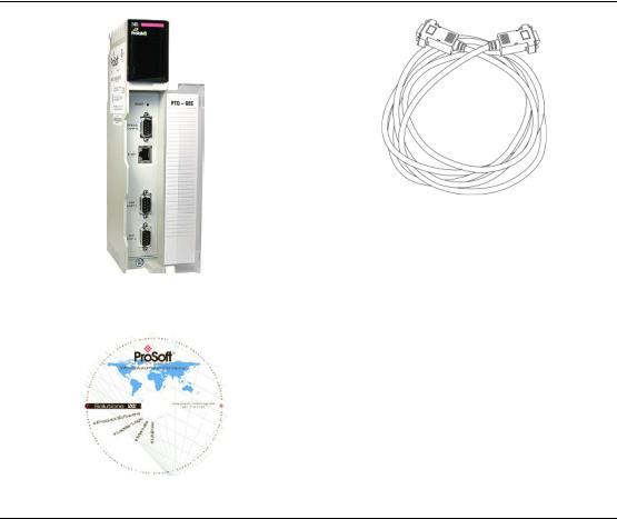
1.1.1 Package Contents
ProTalk Module |
Null Modem Serial Cable |
ProSoft Solutions DVD
1.1.2 Quantum Hardware
This guide assumes that you are familiar with the installation and setup of the Quantum hardware. The following should be installed, configured, and powered up before proceeding:
Quantum Processor
Quantum rack
Quantum power supply
Quantum Modbus Plus Network Option Module (NOM) (optional)
Quantum to PC programming hardware
NOM Ethernet or Serial connection to PC
Page 12 of 201 |
ProSoft Technology, Inc. |
|
March 4, 2013 |

48TPTQ-104S Rev 1 |
♦47TQuantum Platform |
Start Here |
46TIEC 60870-5-104 |
Server for Quantum |
12TUser Manual |
|
|
|
1.1.3 PC and Software
Windows-based PC with at least one COM port
Quantum programming software installed on machine or
Concept™ PLC Programming Software version 2.6
or
ProWORX PLC Programming Software or
Unity™ Pro PLC Programming Software
Note: ProTalk modules are compatible with common Quantum programming applications, including Concept and Unity Pro. For all other programming applications, please contact technical support.
1.2Install ProSoft Configuration Builder Software
This manual is meant for use of PTQ-104S Rev1. PCB version 2.2.0 and older must be used for Rev1. Older versions of PCB can be found at http://www.prosoft-technology.com/pcb
ProSoft Configuration Builder (PCB) software is used to configure the module.
To install ProSoft Configuration Builder from the ProSoft Web Site
1Open your web browser and navigate to http://www.prosofttechnology.com/pcb
2Click the DOWNLOAD HERE link to download the appropriate version of ProSoft Configuration Builder.
3Choose SAVE or SAVE FILE when prompted.
4Save the file to your Windows Desktop, so that you can find it easily when you have finished downloading.
5When the download is complete, locate and open the file, and then follow the instructions on your screen to install the program.
If you do not have access to the Internet, you can install ProSoft Configuration Builder from the ProSoft Solutions DVD, included in the package with your module.
To install ProSoft Configuration Builder from the Product DVD
1Insert the ProSoft Solutions Product DVD into the DVD drive of your PC. Wait for the startup screen to appear.
2On the startup screen, click PRODUCT DOCUMENTATION. This action opens a Windows Explorer file tree window.
3Click to open the UTILITIES folder. This folder contains all of the applications and files you will need to set up and configure your module.
ProSoft Technology, Inc. |
Page 13 of 201 |
March 4, 2013 |
|

Start Here |
48TPTQ-104S Rev 1 ♦47TQuantum Platform |
12TUser Manual |
46TIEC 60870-5-104 Server for Quantum |
|
|
4Double-click the SETUP CONFIGURATION TOOL folder, double-click the PCB_*.EXE file and follow the instructions on your screen to install the software on your PC. The information represented by the "*" character in the file name is the PCB version number and, therefore, subject to change as new versions of PCB are released.
Note: Many of the configuration and maintenance procedures use files and other utilities on the DVD. You may wish to copy the files from the Utilities folder on the DVD to a convenient location on your hard drive.
1.3Setting Up the ProTalk Module
After you complete the following procedures, the ProTalk module will actively be transferring data bi-directionally with the processor.
1.3.1 Install the ProTalk Module in the Quantum Rack
Verify Jumper Settings
ProTalk modules are configured for RS-232 serial communications by default. To use RS-422 or RS-485, you must change the jumpers.
The jumpers are located on the back of the module as shown in the following illustration:
Page 14 of 201 |
ProSoft Technology, Inc. |
|
March 4, 2013 |
48TPTQ-104S Rev 1 |
♦47TQuantum Platform |
Start Here |
46TIEC 60870-5-104 |
Server for Quantum |
12TUser Manual |
|
|
|
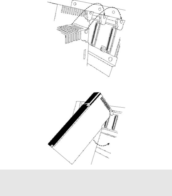
Install the ProTalk Module in the Quantum Rack
1Place the Module in the Quantum Rack. The ProTalk module must be placed in the same rack as the processor.
2Tilt the module at a 45° angle and align the pegs at the top of the module with slots on the backplane.
3 Push the module into place until it seats firmly in the backplane.
Caution: The PTQ module is hot-swappable, meaning that you can install and remove it while the rack is powered up. You should not assume that this is the case for all types of modules unless the user manual for the product explicitly states that the module is hot-swappable. Failure to observe this precaution could result in damage to the module and any equipment connected to it.
ProSoft Technology, Inc. |
Page 15 of 201 |
March 4, 2013 |
|
Start Here |
48TPTQ-104S Rev 1 ♦47TQuantum Platform |
12TUser Manual |
46TIEC 60870-5-104 Server for Quantum |
|
|
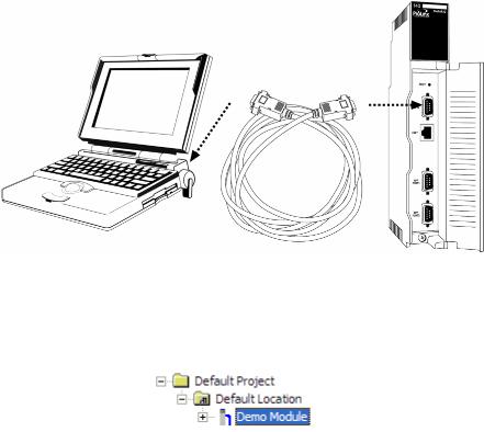
1.3.2 Connect the PC to the ProTalk Configuration/Debug Port
Make sure you have exited the Quantum programming software before performing these steps. This action will avoid serial port conflict.
Using the supplied Null Modem cable, connect your PC to the Configuration/Debug port on the ProTalk module as shown
To connect to the module’s Configuration/Debug serial port:
1Start PCB, and then select the module to test. Click the right mouse button to open a shortcut menu.
Page 16 of 201 |
ProSoft Technology, Inc. |
|
March 4, 2013 |

48TPTQ-104S Rev 1 |
♦47TQuantum Platform |
Start Here |
46TIEC 60870-5-104 |
Server for Quantum |
12TUser Manual |
|
|
|
2 On the shortcut menu, choose DIAGNOSTICS.
This action opens the DIAGNOSTICS dialog box. 3 Press [?] to open the Main Menu.
Important: The illustrations of configuration/debug menus in this section are intended as a general guide, and may not exactly match the configuration/debug menus in your own module.
ProSoft Technology, Inc. |
Page 17 of 201 |
March 4, 2013 |
|
Start Here |
48TPTQ-104S Rev 1 ♦47TQuantum Platform |
12TUser Manual |
46TIEC 60870-5-104 Server for Quantum |
|
|
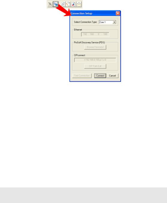
If there is no response from the module, follow these steps:
1Click to configure the connection. On the Connection Setup dialog box, select a valid com port or other connection type supported by the module.
2Verify that the null modem cable is connected properly between your computer’s serial port and the module. A regular serial cable will not work.
3On computers with more than one serial port, verify that your communication program is connected to the same port that is connected to the module.
4If you are still not able to establish a connection, contact ProSoft Technology for assistance.
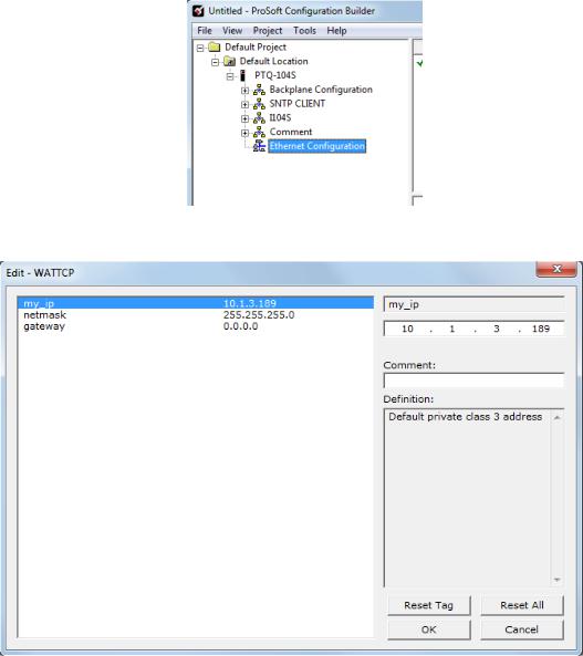
1.3.3Ethernet Configuration
Use this procedure to configure the Ethernet settings for your module. You must assign an IP address, subnet mask and module address. After you complete this step and download the configuration to the module, you can connect to the module with an Ethernet cable.
1Determine the network settings for your module, with the help of your network administrator if necessary. You will need the following information:
o IP address (fixed IP required) _____ . _____ . _____ . _____
o |
Subnet mask |
_____ . _____ . _____ . _____ |
o |
Gateway address |
_____ . _____ . _____ . _____ |
Note: The module Address is optional, and is not required for networks that do not use a default module.
Page 18 of 201 |
ProSoft Technology, Inc. |
|
March 4, 2013 |
48TPTQ-104S Rev 1 |
♦47TQuantum Platform |
Start Here |
46TIEC 60870-5-104 |
Server for Quantum |
12TUser Manual |
|
|
|
2 Double-click the ETHERNET CONFIGURATION icon.
3 This action opens the EDIT dialog box.
4Edit the values for my_ip, netmask (subnet mask) and gateway (default gateway).
5When finished editing, click OK to save the changes and return to the ProSoft Configuration Builder window.
ProSoft Technology, Inc. |
Page 19 of 201 |
March 4, 2013 |
|
Start Here |
48TPTQ-104S Rev 1 ♦47TQuantum Platform |
12TUser Manual |
46TIEC 60870-5-104 Server for Quantum |
|
|
Page 20 of 201 |
ProSoft Technology, Inc. |
|
March 4, 2013 |
48TPTQ-104S Rev 1 |
♦47TQuantum Platform |
Configuring the Processor with Unity Pro |
46TIEC 60870-5-104 |
Server for Quantum |
12TUser Manual |
|
|
|
2 Configuring the Processor with Unity Pro
In This Chapter |
|
Create a New Project ............................................................................ |
22 |
Add the PTQ Module to the Project....................................................... |
24 |
Build the Project .................................................................................... |
25 |
Connect Your PC to the Processor ....................................................... |
26 |
Download the Project to the Processor ................................................. |
28 |
The following steps are designed to ensure that the processor (Quantum or Unity) is able to transfer data successfully with the PTQ module. As part of this procedure, you will use Unity Pro to create a project, add the PTQ module to the project, set up data memory for the project, and then download the project to the processor.
ProSoft Technology, Inc. |
Page 21 of 201 |
March 4, 2013 |
|

Configuring the Processor with Unity Pro |
48TPTQ-104S Rev 1 ♦47TQuantum Platform |
12TUser Manual |
46TIEC 60870-5-104 Server for Quantum |
|
|
2.1Create a New Project
The first step is to open Unity Pro and create a new project.
1In the New Project dialog box, choose the CPU type. In the following illustration, the CPU is 140 CPU 651 60. Choose the processor type that matches your own hardware configuration, if it differs from the example. Click OK to continue.
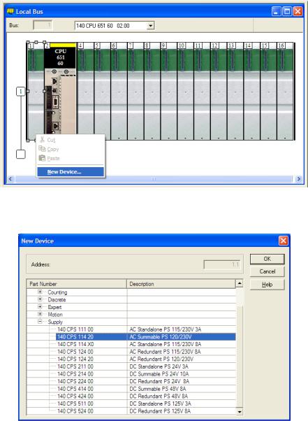
2Next, add a power supply to the project. In the Project Browser, expand the Configuration folder, and then double-click the 1:LOCALBUS icon. This action opens a graphical window showing the arrangement of devices in your Quantum rack.
Page 22 of 201 |
ProSoft Technology, Inc. |
|
March 4, 2013 |
48TPTQ-104S Rev 1 |
♦47TQuantum Platform |
Configuring the Processor with Unity Pro |
46TIEC 60870-5-104 |
Server for Quantum |
12TUser Manual |
|
|
|
3Select the rack position for the power supply, and then click the right mouse button to open a shortcut menu. On the shortcut menu, choose NEW DEVICE.
4Expand the Supply folder, and then select your power supply from the list. Click OK to continue.
5 Repeat these steps to add any additional devices to your Quantum Rack.
ProSoft Technology, Inc. |
Page 23 of 201 |
March 4, 2013 |
|

Configuring the Processor with Unity Pro |
48TPTQ-104S Rev 1 ♦47TQuantum Platform |
12TUser Manual |
46TIEC 60870-5-104 Server for Quantum |
|
|
2.2Add the PTQ Module to the Project
1Expand the Communication tree, and select GEN NOM. This module type provides extended communication capabilities for the Quantum system, and allows communication between the PLC and the PTQ module without requiring additional programming.
2Next, enter the module personality value. The correct value for ProTalk modules is 1060 decimal (0424 hex).
Page 24 of 201 |
ProSoft Technology, Inc. |
|
March 4, 2013 |

48TPTQ-104S Rev 1 |
♦47TQuantum Platform |
Configuring the Processor with Unity Pro |
46TIEC 60870-5-104 |
Server for Quantum |
12TUser Manual |
|
|
|
3Before you can save the project in Unity Pro, you must validate the modifications. Open the EDIT menu, and then choose VALIDATE. If no errors are reported, you can save the project.
4SAVE the project.
2.3Build the Project
Whenever you update the configuration of your PTQ module or the processor, you must import the changed configuration from the module, and then build (compile) the project before downloading it to the processor.
Note: The following steps show you how to build the project in Unity Pro. This is not intended to provide detailed information on using Unity Pro, or debugging your programs. Refer to the documentation for your processor and for Unity Pro for specialized information.
To build (compile) the project
1Review the elements of the project in the Project Browser.
2When you are satisfied that you are ready to download the project, open the BUILD menu, and then choose REBUILD ALL PROJECT. This action builds (compiles) the project into a form that the processor can use to execute the instructions in the project file. This task may take several minutes, depending on the complexity of the project and the resources available on your PC.
3As the project is built, Unity Pro reports its process in a Progress dialog box, with details appearing in a pane at the bottom of the window. The following illustration shows the build process under way.
ProSoft Technology, Inc. |
Page 25 of 201 |
March 4, 2013 |
|
Configuring the Processor with Unity Pro |
48TPTQ-104S Rev 1 ♦47TQuantum Platform |
12TUser Manual |
46TIEC 60870-5-104 Server for Quantum |
|
|
After the build process is completed successfully, the next step is to download the compiled project to the processor.
2.4Connect Your PC to the Processor
The next step is to connect to the processor so that you can download the project file. The processor uses this project file to communicate over the backplane to modules identified in the project file.
Note: If you have never connected from the PC to your processor before, you must verify that the necessary port drivers are installed and available to Unity Pro.
To verify address and driver settings in Unity Pro
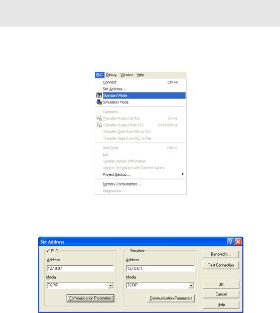
1Open the PLC menu, and choose STANDARD MODE. This action turns off the PLC Simulator, and allows you to communicate directly with the Quantum or Unity hardware.
2Open the PLC menu, and choose SET ADDRESS... This action opens the Set Address dialog box. Open the MEDIA dropdown list and choose the connection type to use (TCPIP or USB).
Page 26 of 201 |
ProSoft Technology, Inc. |
|
March 4, 2013 |

48TPTQ-104S Rev 1 |
♦47TQuantum Platform |
Configuring the Processor with Unity Pro |
46TIEC 60870-5-104 |
Server for Quantum |
12TUser Manual |
|
|
|
3If the MEDIA dropdown list does not contain the connection method you wish to use, click the COMMUNICATION PARAMETERS button in the PLC area of the dialog box. This action opens the PLC Communication Parameters dialog box.
4Click the DRIVER SETTINGS button to open the SCHNEIDER Drivers management Properties dialog box.
5Click the INSTALL/UPDATE button to specify the location of the Setup.exe file containing the drivers to use. You will need your Unity Pro installation disks for this step.
6Click the BROWSE button to locate the Setup.exe file to execute, and then execute the setup program. After the installation, restart your PC if you are prompted to do so. Refer to your Schneider Electric documentation for more information on installing drivers for Unity Pro.
ProSoft Technology, Inc. |
Page 27 of 201 |
March 4, 2013 |
|
Configuring the Processor with Unity Pro |
48TPTQ-104S Rev 1 ♦47TQuantum Platform |
12TUser Manual |
46TIEC 60870-5-104 Server for Quantum |
|
|
2.4.1 Connecting to the Processor with TCP/IP
The next step is to download (copy) the project file to the processor. The following steps demonstrate how to use an Ethernet cable connected from the Processor to your PC through an Ethernet hub or switch. Other connection methods may also be available, depending on the hardware configuration of your processor, and the communication drivers installed in Unity Pro.
1If you have not already done so, connect your PC and the processor to an Ethernet hub.
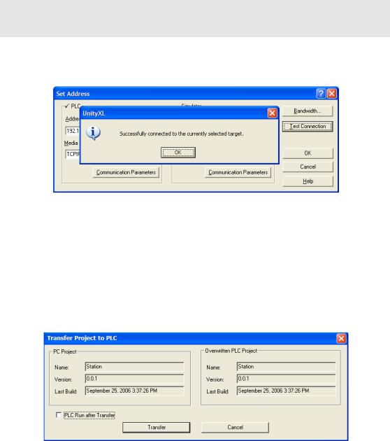
2Open the PLC menu, and then choose SET ADDRESS.
Important: Notice that the Set Address dialog box is divided into two areas. Enter the address
and media type in the PLC area of the dialog box, not the SIMULATOR area.
3Enter the IP address in the address field. In the MEDIA dropdown list, choose TCPIP.
4Click the TEST CONNECTION button to verify that your settings are correct.
2.5Download the Project to the Processor
1Open the PLC menu and then choose CONNECT. This action opens a connection between the Unity Pro software and the processor, using the address and media type settings you configured in the previous step.
2On the PLC menu, choose TRANSFER PROJECT TO PLC. This action opens the TRANSFER PROJECT TO PLC dialog box. If you would like the PLC to go to "Run" mode immediately after the transfer is complete, select (check) the
PLC RUN AFTER TRANSFER check box.
Page 28 of 201 |
ProSoft Technology, Inc. |
|
March 4, 2013 |
48TPTQ-104S Rev 1 |
♦47TQuantum Platform |
Configuring the Processor with Unity Pro |
46TIEC 60870-5-104 |
Server for Quantum |
12TUser Manual |
|
|
|
3Click the TRANSFER button to download the project to the processor. As the project is transferred, Unity Pro reports its process in a PROGRESS dialog box, with details appearing in a pane at the bottom of the window.
When the transfer is complete, place the processor in Run mode.
ProSoft Technology, Inc. |
Page 29 of 201 |
March 4, 2013 |
|
Configuring the Processor with Unity Pro |
48TPTQ-104S Rev 1 ♦47TQuantum Platform |
12TUser Manual |
46TIEC 60870-5-104 Server for Quantum |
|
|
Page 30 of 201 |
ProSoft Technology, Inc. |
|
March 4, 2013 |
Loading...