


MVI56-PDPMV1
ControlLogix Platform
PROFIBUS DPV1 Master
March 22, 2011
USER MANUAL
Your Feedback Please
We always want you to feel that you made the right decision to use our products. If you have suggestions, comments, compliments or complaints about our products, documentation, or support, please write or call us.
How to Contact Us
ProSoft Technology
5201 Truxtun Ave., 3rd Floor Bakersfield, CA 93309
+1 (661) 716-5100
+1 (661) 716-5101 (Fax) www.prosoft-technology.com support@prosoft-technology.com
Copyright © 2011 ProSoft Technology, Inc., all rights reserved.
MVI56-PDPMV1 User Manual
March 22, 2011
ProSoft Technology ®, ProLinx ®, inRAx ®, ProTalk ®, and RadioLinx ® are Registered Trademarks of ProSoft Technology, Inc. All other brand or product names are or may be trademarks of, and are used to identify products and services of, their respective owners.
ProSoft Technology® Product Documentation
In an effort to conserve paper, ProSoft Technology no longer includes printed manuals with our product shipments. User Manuals, Datasheets, Sample Ladder Files, and Configuration Files are provided on the enclosed CD-ROM in Adobe® Acrobat Reader file format (.PDFs). These product documentation files may also be freely downloaded from our web site: www.prosoft-technology.com

Important Installation Instructions
Power, Input, and Output (I/O) wiring must be in accordance with Class I, Division 2 wiring methods, Article 501-4 (b) of the National Electrical Code, NFPA 70 for installation in the U.S., or as specified in Section 18-1J2 of the Canadian Electrical Code for installations in Canada, and in accordance with the authority having jurisdiction. The following warnings must be heeded:
WARNING - EXPLOSION HAZARD - SUBSTITUTION OF COMPONENTS MAY IMPAIR SUITABILITY FOR CLASS I, DIV. 2;
WARNING - EXPLOSION HAZARD - WHEN IN HAZARDOUS LOCATIONS, TURN OFF POWER BEFORE REPLACING OR WIRING MODULES
WARNING - EXPLOSION HAZARD - DO NOT DISCONNECT EQUIPMENT UNLESS POWER HAS BEEN SWITCHED OFF OR THE AREA IS KNOWN TO BE NON-HAZARDOUS.
THIS DEVICE SHALL BE POWERED BY CLASS 2 OUTPUTS ONLY.
MVI (Multi Vendor Interface) Modules
WARNING - EXPLOSION HAZARD - DO NOT DISCONNECT EQUIPMENT UNLESS POWER HAS BEEN SWITCHED OFF OR THE AREA IS KNOWN TO BE NON-HAZARDOUS.
AVERTISSEMENT - RISQUE D'EXPLOSION - AVANT DE DÉCONNECTER L'ÉQUIPEMENT, COUPER LE COURANT OU S'ASSURER QUE L'EMPLACEMENT EST DÉSIGNÉ NON DANGEREUX.
Warnings
North America Warnings
AWarning - Explosion Hazard - Substitution of components may impair suitability for Class I, Division 2.
BWarning - Explosion Hazard - When in Hazardous Locations, turn off power before replacing or rewiring modules.
Warning - Explosion Hazard - Do not disconnect equipment unless power has been switched off or the area is known to be nonhazardous.
CSuitable for use in Class I, Division 2, Groups A, B, C, and D Hazardous Locations or Non-Hazardous Locations.
ATEX Warnings and Conditions of Safe Usage
Power, Input, and Output (I/O) wiring must be in accordance with the authority having jurisdiction
AWarning - Explosion Hazard - When in hazardous locations, turn off power before replacing or wiring modules.
BWarning - Explosion Hazard - Do not disconnect equipment unless power has been switched off or the area is known to be non-hazardous.
CThese products are intended to be mounted in an IP54 enclosure. The devices shall provide external means to prevent the rated voltage being exceeded by transient disturbances of more than 40%. This device must be used only with ATEX certified backplanes.
DDO NOT OPEN WHEN ENERGIZED.
Battery Life Advisory
The MVI46, MVI56, MVI56E, MVI69, and MVI71 modules use a rechargeable Lithium Vanadium Pentoxide battery to backup the real-time clock and CMOS. The battery should last for the life of the module. The module must be powered for approximately twenty hours before the battery becomes fully charged. After it is fully charged, the battery provides backup power for the CMOS setup and the real-time clock for approximately 21 days. When the battery is fully discharged, the module will revert to the default BIOS and clock settings.
Note: The battery is not user replaceable.

Markings
Electrical Ratings
Backplane Current Load: 800 mA @ 5 Vdc; 3 mA @ 24 Vdc
Operating Temperature: 32°F to 140°F (0°C to 60°C)
Storage Temperature: -40°F to 185°F (-40°C to 85°C)
Shock: 30 g operational; 50 g non-operational; Vibration: 5 g from 10 Hz to 150 Hz
Relative Humidity 5% to 95% (with no condensation)
All phase conductor sizes must be at least 1.3 mm (squared) and all earth ground conductors must be at least 4mm (squared).
Label Markings
<Ex> II 3 G
Ex nA IIc T6 X
0°C <= Tamb <= 60°C
Agency Approvals and Certifications
CE |
EMC-EN61326-1:2006; EN61000-6-4:2007 |
||
|
|
|
|
CB Safety |
CA/10533/CSA IEC 61010-1 Ed. 2, |
||
|
CB 243333-2056722 (2090408) |
||
|
|
|
|
GOST-R |
EN61010 |
||
|
|
|
|
CSA |
61010 |
|
|
|
|
|
|
DNV |
DET NORSKE VERITAS Test 2.4 |
||
|
|
|
|
Lloyds |
Lloyds Register Test Specification Number 1,2002 |
||
|
|
|
|
ATEX |
EN 60079-0:July 2006; EN60079-15:Oct 2005 |
||
|
|
|
|
|
|
|
|
243333 |
ME06 |
MVI56-PDPMV1 ♦ ControlLogix Platform |
Contents |
PROFIBUS DPV1 Master |
User Manual |
|
|
Contents
|
|
Your Feedback Please........................................................................................................................ |
2 |
||
|
|
How to Contact Us .............................................................................................................................. |
2 |
||
|
|
ProSoft Technology® Product Documentation .................................................................................... |
2 |
||
|
|
Important Installation Instructions ....................................................................................................... |
3 |
||
|
|
MVI (Multi Vendor Interface) Modules ................................................................................................ |
3 |
||
|
|
Warnings ............................................................................................................................................. |
|
3 |
|
|
|
Battery Life Advisory ........................................................................................................................... |
3 |
||
|
|
Markings.............................................................................................................................................. |
|
4 |
|
|
Guide to the MVI56-PDPMV1 User Manual |
9 |
|||
|
|
|
|
|
|
|
1 |
Start Here |
|
11 |
|
|
|
|
|
|
|
|
|
1.1 |
System Requirements ............................................................................................. |
12 |
|
|
|
1.2 |
Package Contents ................................................................................................... |
13 |
|
|
|
1.3 |
Installing ProSoft Configuration Builder Software ................................................... |
14 |
|
|
|
1.4 |
Installing the Module in the Rack ............................................................................ |
15 |
|
|
|
1.5 |
Choosing Sample Ladder Logic For Your Application ............................................ |
16 |
|
|
|
1.5.1 |
Determining the Firmware Version of Your Processor............................................ |
17 |
|
|
|
1.5.2 |
Determining the Firmware Version of the MVI56-PDPMV1 Module ....................... |
18 |
|
|
|
1.5.3 |
Determining the Module Mode (LEGACY or FLEX)................................................ |
20 |
|
|
|
1.5.4 |
Sample Program Summary..................................................................................... |
22 |
|
|
|
1.6 |
Using the MVI56-PDPMV1 Sample Ladder Logic .................................................. |
23 |
|
|
|
1.7 |
Using the MVI56-PDPMV1 Add-On Instruction ...................................................... |
24 |
|
|
|
1.7.1 |
LEGACY Sample Add-On Instruction Import Procedure ........................................ |
24 |
|
|
|
1.7.2 |
FLEX Sample Add-On Instruction Import Procedure .............................................. |
38 |
|
|
|
1.8 |
Common Settings for All Sample Programs............................................................ |
65 |
|
|
|
1.8.1 |
Choosing the Controller Type ................................................................................. |
65 |
|
|
|
1.8.2 |
Selecting the Slot Number for the Module .............................................................. |
68 |
|
|
|
1.8.3 |
Selecting the Connection Parameters for the Module ............................................ |
69 |
|
|
|
1.8.4 |
Selecting the RPI Time for the Module ................................................................... |
71 |
|
|
|
1.8.5 |
Changing and Importing Configuration Changes (for PCB v 2.2.0 and up only) .... 72 |
||
|
|
1.9 |
Downloading the Sample Program to the Processor .............................................. |
76 |
|
|
|
1.10 |
Connecting Your PC to the Module......................................................................... |
77 |
|
|
2 |
Configuring the MVI56-PDPMV1 Module |
79 |
||
|
|
|
|
|
|
|
|
2.1 |
Setting Up the Project ............................................................................................. |
80 |
|
|
|
2.2 |
Setting Module Parameters..................................................................................... |
82 |
|
|
|
2.3 |
Configuring the PROFIBUS Master ........................................................................ |
84 |
|
|
|
2.3.1 |
Installing the GSD Files........................................................................................... |
85 |
|
|
|
2.3.2 |
Configuring the PROFIBUS Slaves......................................................................... |
86 |
|
|
|
2.3.3 |
Printing the Processor Network Memory Map....................................................... |
104 |
|
|
|
2.3.4 |
Exporting the Processor Files Prior to PCB v2.2.0 ............................................... |
105 |
|
|
|
2.3.5 |
Exporting the Processor Files for PCB v2.2.0 or later .......................................... |
107 |
|
|
|
2.3.6 |
Backing Up the Project.......................................................................................... |
109 |
|
|
|
2.4 |
Downloading the Project to the Module ................................................................ |
111 |
|
|
|
2.4.1 |
Example 1: Local Rack Application ....................................................................... |
113 |
|
|
|
|
|
|
|
ProSoft Technology, Inc. |
|
Page 5 of 255 |
|||
March 22, 2011 |
|
|
|
||

Contents |
MVI56-PDPMV1 ♦ ControlLogix Platform |
|
User Manual |
|
PROFIBUS DPV1 Master |
2.4.2 |
Example 2: Remote Rack Application .................................................................. |
117 |
2.5 |
Verifying Correct Operation .................................................................................. |
123 |
2.5.1 |
Checking the PROFIBUS LEDs on the MVI56-PDPMV1 ..................................... |
123 |
2.5.2 |
Viewing the Online Status of the PROFIBUS Network......................................... |
124 |
2.5.3Viewing the Fieldbus Data from the MVI56-PDPMV1’s Configuration/Debug Menu126
|
|
2.5.4 |
Viewing the Controller Tags in RSLogix 5000 ...................................................... |
129 |
|
|
|
2.5.5 |
Sending a Mailbox Message in RSLogix 5000 ..................................................... |
130 |
|
3 |
Mailbox Messaging |
133 |
|||
|
|
|
|
|
|
|
|
3.1 |
Mailbox Message Queuing ................................................................................... |
134 |
|
|
|
3.1.1 |
Queue Timeouts ................................................................................................... |
134 |
|
|
|
3.2 |
Flex Mode Mailbox Communication...................................................................... |
135 |
|
|
|
3.2.1 |
Using FLEX Mode MSG Instructions .................................................................... |
136 |
|
|
|
3.2.2 |
Retrieving Status Information ............................................................................... |
137 |
|
|
|
3.2.3 |
Sending Mailbox Commands................................................................................ |
139 |
|
|
|
3.2.4 |
Reading Alarms .................................................................................................... |
143 |
|
|
|
3.2.5 |
Rebooting the Module........................................................................................... |
144 |
|
|
|
3.3 |
Legacy Mode Mailbox Communication................................................................. |
145 |
|
|
|
3.3.1 |
Input Mailbox: Legacy Mode................................................................................. |
145 |
|
|
|
3.3.2 |
Output Mailbox: Legacy Mode .............................................................................. |
146 |
|
|
|
3.3.3 |
Receiving Mailbox Message Responses from the Module: Legacy Mode ........... |
146 |
|
|
|
3.4 |
Special Function Mailbox Messaging Commands................................................ |
148 |
|
|
|
3.5 |
Mailbox Message Commands .............................................................................. |
150 |
|
|
|
3.5.1 |
Mailbox Message: Set Slave Mode ...................................................................... |
150 |
|
|
|
3.5.2 |
Mailbox Message: Get Slave Diagnostics ............................................................ |
153 |
|
|
|
3.5.3 |
Mailbox Message: Get Slave Configuration ......................................................... |
155 |
|
|
|
3.5.4 |
Mailbox Message: Set Slave Address .................................................................. |
157 |
|
|
|
3.5.5 |
Mailbox Message: Get Live List............................................................................ |
160 |
|
|
|
3.5.6 |
Mailbox Message: Acyclic Data Read: Class 1 .................................................... |
161 |
|
|
|
3.5.7 |
Mailbox Message: Acyclic Data Write: Class 1 .................................................... |
164 |
|
|
|
3.5.8 |
Mailbox Message: Alarm Indication ...................................................................... |
165 |
|
|
|
3.5.9 |
Mailbox Message: Set Operating Mode ............................................................... |
167 |
|
|
|
3.5.10 |
Mailbox Message: Start Slave .............................................................................. |
169 |
|
|
|
3.5.11 |
Mailbox Message: Stop Slave .............................................................................. |
170 |
|
|
|
3.6 |
Mailbox Messaging Error Codes........................................................................... |
173 |
|
|
|
3.6.1 |
Acyclic Message Status Word .............................................................................. |
173 |
|
|
|
3.6.2 |
Return Codes........................................................................................................ |
174 |
|
|
|
3.6.3 |
Error Codes........................................................................................................... |
175 |
|
|
|
3.6.4 |
DP-V1 Error Codes ............................................................................................... |
176 |
|
4 |
Diagnostics and Troubleshooting |
177 |
|||
|
|
|
|
|
|
|
|
4.1 |
Basic Troubleshooting Steps ................................................................................ |
178 |
|
|
|
4.2 |
LED Status Indicators: Front of MVI56 Module .................................................... |
179 |
|
|
|
4.2.1 |
Module Faceplate Status Indicators ..................................................................... |
179 |
|
|
|
4.2.2 |
PROFIBUS Master Indicators............................................................................... |
180 |
|
|
|
4.2.3 |
Examples .............................................................................................................. |
180 |
|
|
|
4.2.4 |
Legacy Mode (Use Legacy Mode = Yes) ............................................................. |
182 |
|
|
|
4.2.5 |
Flex Mode (Use Legacy Mode=No)...................................................................... |
183 |
|
|
|
4.3 |
Using ProSoft Configuration Builder (PCB) for Diagnostics ................................. |
184 |
|
|
|
4.3.1 |
Disabling the RSLinx Driver for the Com Port on the PC ..................................... |
184 |
|
|
|
4.3.2 |
RS-232 Configuration/Debug Port ........................................................................ |
186 |
|
|
|
|
|
||
Page 6 of 255 |
ProSoft Technology, Inc. |
||||
|
|
|
March 22, 2011 |
||
MVI56-PDPMV1 ♦ ControlLogix Platform |
Contents |
||||
PROFIBUS DPV1 Master |
|
User Manual |
|||
|
|
|
|
|
|
|
|
4.3.3 |
DB9 to RJ45 Adaptor (Cable 14) .......................................................................... |
186 |
|
|
|
4.3.4 |
Using the Diagnostic Window in ProSoft Configuration Builder............................ |
187 |
|
5 |
Reference |
|
197 |
||
|
|
|
|
|
|
|
|
5.1 |
Product Specifications........................................................................................... |
198 |
|
|
|
5.1.1 |
General Specifications .......................................................................................... |
198 |
|
|
|
5.1.2 |
Hardware Specifications........................................................................................ |
199 |
|
|
|
5.1.3 |
Functional Specifications....................................................................................... |
199 |
|
|
|
5.2 |
About the PROFIBUS Protocol ............................................................................. |
201 |
|
|
|
5.2.1 |
PROFIBUS DP Architecture.................................................................................. |
201 |
|
|
|
5.2.2 |
Bus Access............................................................................................................ |
201 |
|
|
|
5.2.3 |
Master/Slave Communication Phases .................................................................. |
202 |
|
|
|
5.2.4 |
How Cable Length Affects Communication Rate .................................................. |
202 |
|
|
|
5.2.5 |
PROFIBUS Master Port ........................................................................................ |
203 |
|
|
|
5.2.6 |
Constructing a Bus Cable for PROFIBUS DP....................................................... |
204 |
|
|
|
5.2.7 |
Supported PROFIBUS Services ........................................................................... |
208 |
|
|
|
5.3 |
PROFIBUS comDTM ............................................................................................ |
209 |
|
|
|
5.3.1 |
ProSoft Technology Product Availability ............................................................... |
209 |
|
|
|
5.3.2 |
Introduction to PROFIBUS comDTM .................................................................... |
210 |
|
|
|
5.3.3 |
System Requirements ........................................................................................... |
212 |
|
|
|
5.3.4 |
Installation ............................................................................................................. |
213 |
|
|
|
5.3.5 |
Quick Start............................................................................................................. |
215 |
|
|
|
5.3.6 |
Verifying the comDTM Version and comDTM Install Version ............................... |
223 |
|
|
|
5.4 |
Module Functional Overview ................................................................................. |
229 |
|
|
|
5.4.1 |
Legacy Mode Input and Output Data Blocks......................................................... |
230 |
|
|
|
5.4.2 |
Flex Mode Input and Output Data Blocks ............................................................. |
236 |
|
6 |
Support, Service & Warranty |
245 |
|||
|
|
|
|
|
|
|
|
Contacting Technical Support......................................................................................................... |
245 |
||
|
|
6.1 |
Return Material Authorization (RMA) Policies and Conditions.............................. |
247 |
|
|
|
6.1.1 |
Returning Any Product .......................................................................................... |
247 |
|
|
|
6.1.2 |
Returning Units Under Warranty ........................................................................... |
247 |
|
|
|
6.1.3 |
Returning Units Out of Warranty ........................................................................... |
248 |
|
|
|
6.2 |
LIMITED WARRANTY........................................................................................... |
248 |
|
|
|
6.2.1 |
What Is Covered By This Warranty....................................................................... |
249 |
|
|
|
6.2.2 |
What Is Not Covered By This Warranty ................................................................ |
249 |
|
|
|
6.2.3 |
Disclaimer Regarding High Risk Activities ............................................................ |
250 |
|
|
|
6.2.4 |
Intellectual Property Indemnity.............................................................................. |
250 |
|
|
|
6.2.5 |
Disclaimer of all Other Warranties ........................................................................ |
251 |
|
|
|
6.2.6 |
Limitation of Remedies ** ...................................................................................... |
251 |
|
|
|
6.2.7 |
Time Limit for Bringing Suit ................................................................................... |
252 |
|
|
|
6.2.8 |
No Other Warranties ............................................................................................. |
252 |
|
|
|
6.2.9 |
Allocation of Risks ................................................................................................. |
252 |
|
|
|
6.2.10 |
Controlling Law and Severability........................................................................... |
252 |
|
|
Index |
|
253 |
||
|
|
|
|
|
|
ProSoft Technology, Inc. |
Page 7 of 255 |
March 22, 2011 |
|
Contents |
MVI56-PDPMV1 ♦ ControlLogix Platform |
User Manual |
PROFIBUS DPV1 Master |
|
|
Page 8 of 255 |
ProSoft Technology, Inc. |
|
March 22, 2011 |

MVI56-PDPMV1 ♦ ControlLogix Platform |
Guide to the MVI56-PDPMV1 User Manual |
PROFIBUS DPV1 Master |
User Manual |
|
|
Guide to the MVI56-PDPMV1 User Manual
Function |
|
Section to Read |
Details |
|
|
|
|
Introduction |
→ |
Start Here (page 11) |
This section introduces the customer to the |
(Must Do) |
|
|
module. Included are: package contents, |
|
|
|
system requirements, hardware installation, and |
|
|
|
basic configuration. |
|
|
|
|
|
|
|
|
Diagnostic and |
→ |
Diagnostics and |
This section describes Diagnostic and |
Troubleshooting |
|
Troubleshooting |
Troubleshooting procedures. |
|
|
(page 177) |
|
|
|
|
|
|
|
|
|
Reference |
→ |
Reference (page |
These sections contain general references |
|
|
197) |
associated with this product and its |
Product Specifications |
|
Product |
Specifications.. |
|
|
|
|
|
|
Specifications (page |
|
|
|
198) |
|
|
|
|
|
|
|
|
|
Support, Service, and |
→ |
Support, Service |
This section contains Support, Service and |
Warranty |
|
and Warranty (page |
Warranty information. |
|
|
245) |
|
Index |
|
|
Index of chapters. |
|
|
Index |
|
ProSoft Technology, Inc. |
Page 9 of 255 |
March 22, 2011 |
|
Guide to the MVI56-PDPMV1 User Manual |
MVI56-PDPMV1 ♦ ControlLogix Platform |
User Manual |
PROFIBUS DPV1 Master |
|
|
Page 10 of 255 |
ProSoft Technology, Inc. |
|
March 22, 2011 |
MVI56-PDPMV1 ♦ ControlLogix Platform |
Start Here |
PROFIBUS DPV1 Master |
User Manual |
|
|
1Start Here
In This Chapter |
|
|
|
System Requirements ........................................................................... |
12 |
|
Package Contents ................................................................................. |
13 |
Installing ProSoft Configuration Builder Software.................................. |
14 |
|
Installing the Module in the Rack........................................................... |
15 |
|
Choosing Sample Ladder Logic For Your Application ........................... |
16 |
|
Using the MVI56-PDPMV1 Sample Ladder Logic ................................. |
23 |
|
Using the MVI56-PDPMV1 Add-On Instruction ..................................... |
24 |
|
Common Settings for All Sample Programs .......................................... |
65 |
|
Downloading the Sample Program to the Processor............................. |
76 |
|
Connecting Your PC to the Module ....................................................... |
77 |
|
For most applications, the installation and configuration steps described in this section will work without additional programming. ProSoft Technology strongly recommends that you complete the steps in this chapter before developing a custom application.
After you have verified that the module is installed and communicating successfully with the processor and the PROFIBUS network.
ProSoft Technology, Inc. |
Page 11 of 255 |
March 22, 2011 |
|

Start Here |
MVI56-PDPMV1 ♦ ControlLogix Platform |
User Manual |
PROFIBUS DPV1 Master |
|
|
1.1System Requirements
The MVI56-PDPMV1 module requires the following minimum hardware and software components:
Rockwell Automation ControlLogix processor, with compatible power supply and one free slot in the rack, for the MVI56-PDPMV1 module. The module requires 800 mA of available power.
Rockwell Automation RSLogix 5000 programming software version 2.51 or higher.
Rockwell Automation RSLinx communication software
Pentium® II 450 MHz minimum. Pentium III 733 MHz (or better) recommended
Supported operating systems:
o Microsoft Windows XP Professional with Service Pack 1 or 2
o Microsoft Windows 2000 Professional with Service Pack 1, 2, or 3 o Microsoft Windows Server 2003
128 Mbytes of RAM minimum, 256 Mbytes of RAM recommended
100 Mbytes of free hard disk space (or more based on application
requirements)
256-color VGA graphics adapter, 800 x 600 minimum resolution (True Color 1024 x 768 recommended)
CD-ROM drive
Dial-up Internet connection (Broadband connection recommended)
Approved PROFIBUS cabling and connectors.
Small flat blade screwdriver to secure the PROFIBUS connector to the module
Note: You can install the module in a local or remote rack. For remote rack installation, the module requires Ethernet I/P or ControlNet access to the processor.
|
|
|
|
|
|
|
|
Page 12 of 255 |
ProSoft Technology, Inc. |
||
|
|
March 22, 2011 |
|

MVI56-PDPMV1 ♦ ControlLogix Platform |
Start Here |
PROFIBUS DPV1 Master |
User Manual |
|
|
1.2Package Contents
The following components are included with your MVI56-PDPMV1 module, and are all required for installation and configuration.
Important: Before beginning the installation, please verify that all of the following items are present.
|
|
|
|
|
|
|
|
|
|
|
|
|
Qty. |
Part Name |
Part Number |
Part Description |
|
|
|
|
|
|
|
1 |
MVI56-PDPMV1 |
MVI56-PDPMV1 |
PROFIBUS DPV1 Master |
||
|
|
Module |
|
|
|
|
|
|
|
|
|
1 |
Cable |
Cable #15 - RS232 |
For RS232 between a Personal Computer |
||
|
|
|
Null Modem |
(PC) and the CFG port of the module |
|
|
|
|
|
|
|
1 |
Cable |
Cable #14 - RJ45 |
For connecting the module’s port to Cable |
||
|
|
|
to DB9 Male |
#15 for RS-232 connections |
|
|
|
|
Adapter |
|
|
|
|
|
|
|
|
1 |
inRAx Solutions CD |
|
Contains sample programs, utilities and |
||
|
|
|
|
documentation for the MVI56-PDPMV1 |
|
|
|
|
|
module. |
|
|
|
|
|
|
|
If any of these components are missing, please contact ProSoft Technology Support for replacement parts.
ProSoft Technology, Inc. |
Page 13 of 255 |
March 22, 2011 |
|

Start Here |
MVI56-PDPMV1 ♦ ControlLogix Platform |
User Manual |
PROFIBUS DPV1 Master |
|
|
1.3Installing ProSoft Configuration Builder Software
You must install the ProSoft Configuration Builder (PCB) software to configure the module. You can always get the newest version of ProSoft Configuration Builder from the ProSoft Technology website.
To install ProSoft Configuration Builder from the ProSoft Technology website
1 Open your web browser and navigate to http://www.prosoft-
technology.com/pcb
2Click the DOWNLOAD HERE link to download the latest version of ProSoft
Configuration Builder.
3Choose SAVE or SAVE FILE when prompted.
4Save the file to your Windows Desktop, so that you can find it easily when you have finished downloading.
5When the download is complete, locate and open the file, and then follow the instructions on your screen to install the program.
If you do not have access to the Internet, you can install ProSoft Configuration Builder from the ProSoft Solutions Product CD-ROM, included in the package with your module.
To install ProSoft Configuration Builder from the Product CD-ROM
1Insert the ProSoft Solutions Product CD-ROM into the CD-ROM drive of your
PC. Wait for the startup screen to appear.
2On the startup screen, click PRODUCT DOCUMENTATION. This action opens a
Windows Explorer file tree window.
3Click to open the UTILITIES folder. This folder contains all of the applications
and files you will need to set up and configure your module.
4Double-click the SETUP CONFIGURATION TOOL folder, double-click the PCB_*.EXE file and follow the instructions on your screen to install the software on your PC. The information represented by the "*" character in the file name is the PCB version number and, therefore, subject to change as new versions of PCB are released.
Note: Many of the configuration and maintenance procedures use files and other utilities on the CD-ROM. You may wish to copy the files from the Utilities folder on the CD-ROM to a convenient location on your hard drive.
|
|
|
|
|
|
|
|
Page 14 of 255 |
ProSoft Technology, Inc. |
||
|
|
March 22, 2011 |
|
MVI56-PDPMV1 ♦ ControlLogix Platform |
Start Here |
PROFIBUS DPV1 Master |
User Manual |
|
|
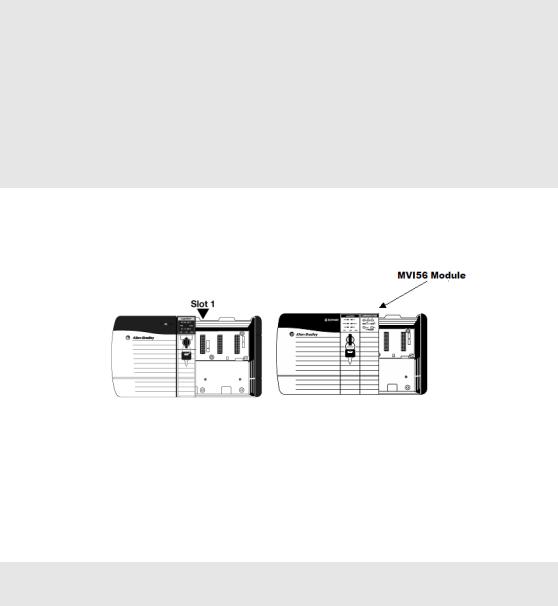
1.4Installing the Module in the Rack
If you have not already installed and configured your ControlLogix processor and power supply, please do so before installing the MVI56-PDPMV1 module. Refer to your Rockwell Automation product documentation for installation instructions.
Warning: You must follow all safety instructions when installing this or any other electronic devices. Failure to follow safety procedures could result in damage to hardware or data, or even serious injury or death to personnel. Refer to the documentation for each device you plan to connect to verify that suitable safety procedures are in place before installing or servicing the device.
Warning: When you insert or remove the module while backplane power is on, an electrical arc can occur. This could cause an explosion in hazardous location installations. Verify that power is removed or the area is non-hazardous before proceeding. Repeated electrical arcing causes excessive wear to contacts on both the module and its mating connector. Worn contacts may create electrical resistance that can affect module operation.
1Turn power OFF.
2Align the module with the top and bottom guides, and slide it into the rack until the module is firmly against the backplane connector.
3 |
With a firm but steady push, snap the module into place. |
4 |
Check that the holding clips on the top and bottom of the module are securely |
|
in the locking holes of the rack. |
5Make a note of the slot location. You must identify the slot in which the module is installed in order for the sample program to work correctly. Slot numbers are identified on the green circuit board (backplane) of the ControlLogix rack.
6Turn power ON.
Note: If you insert the module improperly, the system may stop working, or may behave
unpredictably.
|
|
|
|
|
|
|
|
ProSoft Technology, Inc. |
Page 15 of 255 |
||
March 22, 2011 |
|
|
|

Start Here |
MVI56-PDPMV1 ♦ ControlLogix Platform |
User Manual |
PROFIBUS DPV1 Master |
|
|
1.5Choosing Sample Ladder Logic For Your Application
The sample program for your MVI56-PDPMV1 module includes custom tags, data types and ladder logic for data I/O, status and alarm monitoring, and mailbox messaging. For most applications, you can run the sample ladder program without modification, or, for advanced applications, you can incorporate the sample program into your existing application.
NOTE: ControlLogix firmware versions 15 or earlier do not support Add-On Instructions (AOIs).
For these applications, you will need to use the plain ladder logic sample programs.
For applications with ControlLogix firmware version 16 or newer, you can use the supplied AOI
samples, which encapsulate the ladder logic, controller tags, and user-defined data types into one
convenient import file.
SPECIAL NOTE: For AOI applications created using ProSoft Configuration Builder (PCB) version
2.2.0 or later, the following process of sample ladder selection is not necessary. PCB versions
2.2.0 and up allow you to export custom-made RSLogix 5000 .L5X Rung Import files that precisely
match the module's configuration. Selecting and modifying sample logic will not be required if you
use PCB 2.2.0. or later and follow the procedure found in the topic, Export the Processor Files for
PCB v2.2.0 or later (page 107). For more details, see the section, Using the MVI56-PDPMV1 Add-
On Instructions (page 24).
The inRAx Solutions CD provides several versions of the sample ladder logic. The version number appended to the sample file name (for example, "_v13" or "_v15") indicates which ControlLogix firmware version the sample program was created to match. It is best if the ControlLogix processor firmware version and sample program version match. However, RSLogix 5000 can convert an older version sample to a later ControlLogix firmware version, if necessary.
The following criteria determine which sample program to select:
oProcessor Firmware Version
oMVI56-PDPMV1 module firmware version
oMVI56-PDPMV1 mode used (FLEX or LEGACY)
Note: FLEX mode is available only for module firmware versions 1.21 or later.
The next few topics will help you determine which sample programs will work best for your application.
Page 16 of 255 |
ProSoft Technology, Inc. |
|
March 22, 2011 |

MVI56-PDPMV1 ♦ ControlLogix Platform |
Start Here |
PROFIBUS DPV1 Master |
User Manual |
|
|
1.5.1 Determining the Firmware Version of Your Processor
Important: The RSLinx service must be installed and running on your computer in order for RSLogix to communicate with the processor. Refer to your RSLinx and RSLogix documentation for help configuring and troubleshooting these applications.
1Connect an RS-232 serial cable from the COM (serial) port on your PC to the
|
communication port on the front of the processor. |
2 |
Start RSLogix 5000 and close any existing project that may be loaded. |
3 |
Open the COMMUNICATIONS menu and choose GO ONLINE. RSLogix will |
|
establish communication with the processor. This may take a few moments. |
4When RSLogix has established communication with the processor, the
Connected To Go Online dialog box will open.
5In the Connected To Go Online dialog box, click the GENERAL tab. This tab shows information about the processor, including the Revision (firmware) version. In the following illustration, the firmware version is 17.2.
ProSoft Technology, Inc. |
Page 17 of 255 |
March 22, 2011 |
|
Start Here |
MVI56-PDPMV1 ♦ ControlLogix Platform |
User Manual |
PROFIBUS DPV1 Master |
|
|
1.5.2Determining the Firmware Version of the MVI56-PDPMV1 Module
There are two ways to verify the module firmware version:
Checking the Version During Power-Up
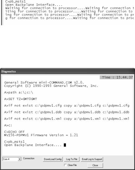
When the module powers up, it will search for the ControlLogix processor to establish backplane connectivity. If the correct ladder is not loaded to the processor, or if the module is not located in the configured slot, or the processor is missing, the module will not allow access to the debug menu and will print the message "Waiting for Connection to the processor…"
Because debug menu access is not allowed at this point, view the debug menu messages that are printed during power-up for the module firmware version. Refer to the message that appears just before the message "C>pb_msts1":
If the message "MVI56-PDPMV1 Firmware Version = x.xx" appears on the screen as shown in the following illustration, the module firmware is version 1.21 or later.
Page 18 of 255 |
ProSoft Technology, Inc. |
|
March 22, 2011 |

MVI56-PDPMV1 ♦ ControlLogix Platform |
Start Here |
PROFIBUS DPV1 Master |
User Manual |
|
|
If the message "MVI56-PDPMV1 Firmware Version = x.xx" does not appear on the screen, the module firmware version is 0.30.
Checking the Version After Power-Up
If the correct sample program (LEGACY or FLEX) is loaded into your processor and the module is located in same slot that was configured, then after module power-up it will be possible to access the debug menu through ProSoft Configuration Builder (PCB).
1Press [?] to display the main menu:
ProSoft Technology, Inc. |
Page 19 of 255 |
March 22, 2011 |
|

Start Here |
MVI56-PDPMV1 ♦ ControlLogix Platform |
User Manual |
PROFIBUS DPV1 Master |
|
|
2Press [V] to display the module version information. Verify "SOFTWARE REVISION LEVEL" for the module firmware version (1.21 for the example below):
1.5.3 Determining the Module Mode (LEGACY or FLEX)
There are two versions of the sample program: LEGACY (fixed I/O sizes) and FLEX (variable I/O sizes) versions.
MVI56-PDPMV1 firmware version 0.30 must use the LEGACY sample program and fixed I/O sizes.
MVI56-PDPMV1 firmware version 1.21 or later can use either the LEGACY or FLEX mode sample programs.
For module firmware version 1.21 or later, the USE LEGACY MODE configuration parameter in ProSoft Configuration Builder selects which mode you will use. Setting the parameter to YES says to use fixed I/O sizes in LEGACY mode. Setting the parameter to NO says to use variable I/O sizes in FLEX mode. This step is described in Select the Connection Parameters for the Module (page 69).
LEGACY mode allows backward compatibility with firmware version 0.30 and implements the following features:
Fixed backplane I/O block size (input size = 250 words, output size = 248 words)
Status and Mailbox transferred through regular I/O blocks.
Page 20 of 255 |
ProSoft Technology, Inc. |
|
March 22, 2011 |
MVI56-PDPMV1 ♦ ControlLogix Platform |
Start Here |
PROFIBUS DPV1 Master |
User Manual |
|
|
LEGACY mode offers these advantages:
Works with all module firmware versions; use LEGACY mode for backward compatibility in older applications.
Since all parameters are fixed, configuration is simpler than FLEX mode.
Status data is bought across the backplane as I/O data without the need for additional logic to trigger MSG instructions.
FLEX mode implements the following features:
Supports variable backplane I/O block sizes (input backplane block size can be set from 12 words to 250 words; output backplane block size can be set from 5 to 248 words).
Status, Slave Diagnostic, and Mailbox data transferred through MSG instructions.
Supports IOT instruction for immediate write of backplane output.
When transfer speed for smaller data configurations is a priority or when backward compatibility is not required, consider using FLEX mode, which provides these advantages:
Makes it easier to support installing the module in a remote rack. The flexible backplane I/O block size allows you to adjust the amount of data to transfer for any specific remote rack application and optimize network bandwidth utilization.
Improves backplane I/O block transfer performance by implementing MSG instructions to retrieve module status. This means regular I/O block transfers are not needed for status data, so process I/O data can be updated more often. The same applies to Mailbox MSG data transfers.
Improves backplane performance by implementing the IOT instruction for Immediate Output Transfers, which overrides the module RPI time and sends data as fast as possible.
ProSoft Technology, Inc. |
Page 21 of 255 |
March 22, 2011 |
|

Start Here |
MVI56-PDPMV1 ♦ ControlLogix Platform |
User Manual |
PROFIBUS DPV1 Master |
|
|
1.5.4 Sample Program Summary
Use the following table to determine which sample program to use for your application.
|
MVI56-PDPMV1 |
ControlLogix |
Use Legacy |
Sample Ladder |
Add-On Instruction |
|
|
Version |
Version |
Mode |
|
|
|
|
|
|
parameter |
|
|
|
|
|
|
value |
|
|
|
|
|
|
|
|
|
|
|
0.30 |
13 |
- |
MVI56PDPMV1_LEGACY_v13.ACD |
- |
|
|
|
|
|
|
|
|
|
0.30 |
15 |
- |
MVI56PDPMV1_LEGACY_v15.ACD |
- |
|
|
|
|
|
|
|
|
|
0.30 |
16 |
- |
MVI56PDPMV1_LEGACY_v16.ACD |
MVI56PDPMV1_LEGACY_v1_3.L5X |
|
|
|
|
|
|
|
|
|
1.21 or later |
13 |
Y (LEGACY) |
MVI56PDPMV1_LEGACY_v13.ACD |
- |
|
|
|
|
|
|
|
|
|
1.21 or later |
15 |
Y (LEGACY) |
MVI56PDPMV1_LEGACY_v15.ACD |
- |
|
|
1.21 or later |
16 |
Y (LEGACY) |
MVI56PDPMV1_LEGACY_v16.ACD |
MVI56PDPMV1_LEGACY_v1_3.L5X |
|
|
|
|
|
|
|
|
|
1.21 or later |
17 |
Y (LEGACY) |
MVI56PDPMV1_LEGACY_v17.ACD |
MVI56PDPMV1_LEGACY_v1_3.L5X |
|
|
1.21 or later |
13 |
N (FLEX) |
MVI56PDPMV1_FLEX_v13.ACD |
- |
|
|
1.21 or later |
15 |
N (FLEX) |
MVI56PDPMV1_FLEX_v15.ACD |
- |
|
|
1.21 or later |
16 |
N (FLEX) |
MVI56PDPMV1_FLEX_v16.ACD |
MVI56PDPMV1_FLEX_v1_2.L5X |
|
|
|
|
|
|
|
|
|
1.21 or later |
17 |
N (FLEX) |
MVI56PDPMV1_FLEX_v17.ACD |
MVI56PDPMV1_FLEX_v1_2.L5X |
|
|
|
|
|
|
|
|
|
|
|
|
|
|
|
|
|
|
|
|
|
|
Note: For ControlLogix version 16, you will use the Add-On Instruction (AOI) rung import (.L5X) files, which encapsulate all the required ladder logic, controller tags, and user-defined data types into a single import file; or you can use the version 16 ladder logic sample files (.ACD), which already have the AOI files imported. The plain ladder logic sample files (.ACD) for versions 13 and 15 use the same logic as the AOI versions but display them as standard ladder logic. The separate AOI .L5K file exists to make it easier to import the sample application into an existing project or new project file. You do not need to import the AOI .L5K files into any of the .ACD ladder logic sample programs. ControlLogix versions 15 and earlier do not support Add-On Instructions; so do not try to import the AOI .L5K files into those older versions of RSLogix 5000.
For ControlLogix firmware version 16, refer to Using the MVI56-PDPMV1 Add-On Instructions (page 24).
For ControlLogix firmware version 15 or older, Using the MVI56-PDPMV1 Sample Ladder Logic (page 23).
|
|
|
|
|
|
|
|
Page 22 of 255 |
ProSoft Technology, Inc. |
||
|
|
March 22, 2011 |
|
MVI56-PDPMV1 ♦ ControlLogix Platform |
Start Here |
PROFIBUS DPV1 Master |
User Manual |
|
|
1.6Using the MVI56-PDPMV1 Sample Ladder Logic
If you will be using ControlLogix firmware versions 16 or higher, you may skip to the section on Using the MVI56-PDPMV1 Add-On Instructions (page 24).
If you will be using ControlLogix firmware versions 13 or 15, then follow this procedure:
1 Copy any of the sample programs you may want to use from the distribution
CD in a convenient folder on your local PC hard drive.
2Start RSLogix 5000 and close any project or programs that may open automatically when the program starts.
3On the FILE menu, click the OPEN button.
4Browse to the location where you saved the sample program files on your local drive and select (left-mouse-click) the one that matches your firmware
version of your ControlLogix processor firmware.
5Left-click the OPEN button.
6RSLogix will load the sample program.
The next step is to configure the correct controller type and slot number for your application. For details, skip to the section on Common Settings for All Sample Programs (page 65).
If you want to add the sample file to an existing application, do the following:
1Open the RSLogix 5000 project .ACD file you wish to use.
2In a separate instance of RSLogix 5000, open the sample ladder logic you
wish to use.
3Follow the procedures for adding a Module to the project and setting Connection Parameters, as found in Creating the MVI56-PDPMV1 Module Profile - Legacy (page 25), Creating the MVI56-PDPMV1 Module Profile - Flex (page 50), and Common Settings for All Sample Programs (page 65).
4Manually copy the user-defined data types from the sample program and paste them into your existing application.
5Manually copy the controller tags from the sample program and paste them into your existing application.
6Manually copy the ladder logic tasks and rungs from the sample program and paste them into your existing application.
ProSoft Technology, Inc. |
Page 23 of 255 |
March 22, 2011 |
|

Start Here |
MVI56-PDPMV1 ♦ ControlLogix Platform |
User Manual |
PROFIBUS DPV1 Master |
|
|
1.7Using the MVI56-PDPMV1 Add-On Instruction
Note: This section applies only for applications with ControlLogix firmware version 16 or higher.
For earlier firmware versions, refer to Using the MVI56-PDPMV1 Sample Ladder Logic (page 23).
The Add-On Instruction (AOI) is supplied already installed as part of a complete
.ACD program file and also as an .L5X ladder import file that can be imported into an existing or new application. Importing the AOI reduces module setup time and simplifies your application logic. The .L5X file automatically imports the following components into an application:
User-defined data types
Controller tags and tag arrays
Add-On Instruction logic
Ladder rung required to call the Add-On Instruction
This section will show the procedure on how to import the Add-On Instruction into your existing ladder for both module modes (LEGACY or FLEX).
1.7.1 LEGACY Sample Add-On Instruction Import Procedure
Note: This section applies only if your application meets one or more of the following conditions:
MVI56-PDPMV1 module firmware version 0.30
MVI56-PDPMV1 module firmware version 1.21 (or later) AND configured in LEGACY mode
(USE LEGACY MODE = YES)
Before You Begin
The following file is required before you start this procedure. Copy the file from the ProSoft Solutions CD-ROM, or download it from www.prosoft-technology.com.
File Name |
Description |
MVI56PDPMV1_LEGACY_v*.L5X
(where * is the current sample program version number)
L5X file containing Add-On Instruction, user-defined data types, controller tags and tag arrays, and ladder logic required to set up the MVI56-PDPMV1 module in Legacy mode
Page 24 of 255 |
ProSoft Technology, Inc. |
|
March 22, 2011 |
MVI56-PDPMV1 ♦ ControlLogix Platform |
Start Here |
PROFIBUS DPV1 Master |
User Manual |
|
|
Creating a New RSLogix5000 Project - Legacy
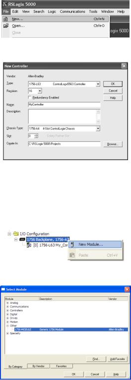
1Open the File menu, and then choose NEW.
2Select Revision 16.
Creating the Module - Legacy
1Add the MVI56-PDPMV1 module to the project.
In the Controller Organization window, select I/O CONFIGURATION and click the right mouse button to open a shortcut menu. On the shortcut menu, choose NEW MODULE.
This action opens the Select Module dialog box.
ProSoft Technology, Inc. |
Page 25 of 255 |
March 22, 2011 |
|

Start Here |
MVI56-PDPMV1 ♦ ControlLogix Platform |
User Manual |
PROFIBUS DPV1 Master |
|
|
2Select the 1756-MODULE (GENERIC 1756 MODULE) from the list and click OK. This action opens the New Module dialog box.
3Set the Module Properties values as follows:
Parameter |
Value |
|
|
Name |
Enter a module identification string. Example: |
|
MVI56PDPMV1 |
|
|
Description |
Enter a description for the module. Example: ProSoft |
|
communication module for PROFIBUS communication. |
|
|
Comm Format |
Select DATA-INT |
|
|
Slot |
Enter the slot number in the rack where the MVI56- |
|
PDPMV1 module is located. |
|
|
Input Assembly Instance |
1 |
|
|
Input Size |
250 |
|
|
Output Assembly Instance |
2 |
|
|
Output Size |
248 |
|
|
Configuration Assembly Instance |
4 |
|
|
Configuration Size |
0 |
|
|
4On the Connection tab, set the RPI value for your project. Click OK to confirm.
Page 26 of 255 |
ProSoft Technology, Inc. |
|
March 22, 2011 |

MVI56-PDPMV1 ♦ ControlLogix Platform |
Start Here |
PROFIBUS DPV1 Master |
User Manual |
|
|
Now the MVI56-PDPMV1 module will be visible in the I/O Configuration section.
Importing the Ladder Rung - LEGACY
Note: ProSoft Configuration Builder (PCB), version 2.2.0, or higher, will allow you to export an .L5X rung import file based on the configuration information you enter in PCB. When using LEGACY mode, these custom export files will be very similar to the provided sample LEGACY AOI Rung Import files.
For additional information on how to export custom-made .L5X files from PCB, please see Exporting the Processor Files (page 105).
1Open your application in RSLogix 5000.
2Expand the Tasks folder, and then expand the MainTask folder.
3On the MainProgram folder, click the right mouse button to open a shortcut menu. On the shortcut menu, choose NEW ROUTINE.
4In the New Routine dialog box, enter the name and description of your routine, and then click OK.
5Select an empty rung in the new routine, and then click the right mouse button to open a shortcut menu. On the shortcut menu, choose IMPORT RUNG.
ProSoft Technology, Inc. |
Page 27 of 255 |
March 22, 2011 |
|

Start Here |
MVI56-PDPMV1 ♦ ControlLogix Platform |
User Manual |
PROFIBUS DPV1 Master |
|
|
6Select the MVI56PDPMV1_LEGACY_v*.ACD standard sample file, or the
MVI56PDPMV1_LEGACY_AddOn_Rung_v1_2.L5X custom file you exported from PCB, and click the IMPORT button.
7A window will be displayed showing the controller tags to be created during the import procedure.
8If you are using the module in a different slot (or remote rack) select the correct connection input and output variables to provide the correct path to the module. If your module is located in Slot 1 of the local rack, this step is not required.
Page 28 of 255 |
ProSoft Technology, Inc. |
|
March 22, 2011 |
MVI56-PDPMV1 ♦ ControlLogix Platform |
Start Here |
PROFIBUS DPV1 Master |
User Manual |
|
|
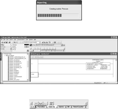
9Click OK to confirm the import. RSLogix will indicate that the import is in progress:
10When the import is completed, the new rung with the Add-On Instruction will be visible as shown in the following illustration.
The procedure has also imported new user-defined data types, controller tags and tag arrays, and the Add-On Instruction to be used at your project.
ProSoft Technology, Inc. |
Page 29 of 255 |
March 22, 2011 |
|

Start Here |
MVI56-PDPMV1 ♦ ControlLogix Platform |
|||
User Manual |
PROFIBUS DPV1 Master |
|||
|
|
|
|
|
|
|
Adding Multiple Modules (Optional) - Legacy |
|
|
|
|
|
|
|
|
|
|
|
|
Important: If your application requires more than one MVI56-PDPMV1 module into the same project, follow the steps below.
1In the I/O Configuration folder, click the right mouse button to open a shortcut menu, and then choose NEW MODULE.
2Select 1756-MODULE.
3Fill the module properties as follows:
Page 30 of 255 |
ProSoft Technology, Inc. |
|
March 22, 2011 |
 Loading...