


MVI46-MCM
SLC Platform
Modbus Communication Module
March 29, 2011
USER MANUAL
Your Feedback Please
We always want you to feel that you made the right decision to use our products. If you have suggestions, comments, compliments or complaints about our products, documentation, or support, please write or call us.
How to Contact Us
ProSoft Technology
5201 Truxtun Ave., 3rd Floor Bakersfield, CA 93309
+1 (661) 716-5100
+1 (661) 716-5101 (Fax) www.prosoft-technology.com support@prosoft-technology.com
Copyright © 2011 ProSoft Technology, Inc., all rights reserved.
MVI46-MCM User Manual
March 29, 2011
ProSoft Technology ®, ProLinx ®, inRAx ®, ProTalk ®, and RadioLinx ® are Registered Trademarks of ProSoft Technology, Inc. All other brand or product names are or may be trademarks of, and are used to identify products and services of, their respective owners.
ProSoft Technology® Product Documentation
In an effort to conserve paper, ProSoft Technology no longer includes printed manuals with our product shipments. User Manuals, Datasheets, Sample Ladder Files, and Configuration Files are provided on the enclosed CD-ROM, and are available at no charge from our web site: www.prosoft-technology.com

Important Installation Instructions
Power, Input, and Output (I/O) wiring must be in accordance with Class I, Division 2 wiring methods, Article 501-4 (b) of the National Electrical Code, NFPA 70 for installation in the U.S., or as specified in Section 18-1J2 of the Canadian Electrical Code for installations in Canada, and in accordance with the authority having jurisdiction. The following warnings must be heeded:
AWARNING - EXPLOSION HAZARD - SUBSTITUTION OF COMPONENTS MAY IMPAIR SUITABILITY FOR CLASS I, DIV. 2;
BWARNING - EXPLOSION HAZARD - WHEN IN HAZARDOUS LOCATIONS, TURN OFF POWER BEFORE REPLACING OR WIRING MODULES
CWARNING - EXPLOSION HAZARD - DO NOT DISCONNECT EQUIPMENT UNLESS POWER HAS BEEN SWITCHED OFF OR THE AREA IS KNOWN TO BE NON-HAZARDOUS.
DTHIS DEVICE SHALL BE POWERED BY CLASS 2 OUTPUTS ONLY.
MVI (Multi Vendor Interface) Modules
WARNING - EXPLOSION HAZARD - DO NOT DISCONNECT EQUIPMENT UNLESS POWER HAS BEEN SWITCHED OFF OR THE AREA IS KNOWN TO BE NON-HAZARDOUS.
AVERTISSEMENT - RISQUE D'EXPLOSION - AVANT DE DÉCONNECTER L'ÉQUIPEMENT, COUPER LE COURANT OU S'ASSURER QUE L'EMPLACEMENT EST DÉSIGNÉ NON DANGEREUX.
Warnings
North America Warnings
AWarning - Explosion Hazard - Substitution of components may impair suitability for Class I, Division 2.
BWarning - Explosion Hazard - When in Hazardous Locations, turn off power before replacing or rewiring modules.
Warning - Explosion Hazard - Do not disconnect equipment unless power has been switched off or the area is known to be nonhazardous.
CSuitable for use in Class I, division 2 Groups A, B, C and D Hazardous Locations or Non-Hazardous Locations.
ATEX Warnings and Conditions of Safe Usage:
Power, Input, and Output (I/O) wiring must be in accordance with the authority having jurisdiction
AWarning - Explosion Hazard - When in hazardous locations, turn off power before replacing or wiring modules.
BWarning - Explosion Hazard - Do not disconnect equipment unless power has been switched off or the area is known to be non-hazardous.
CThese products are intended to be mounted in an IP54 enclosure. The devices shall provide external means to prevent the rated voltage being exceeded by transient disturbances of more than 40%. This device must be used only with ATEX certified backplanes.
DDO NOT OPEN WHEN ENERGIZED.
Warning: This module is not hot-swappable! Always remove power from the rack before inserting or removing this module, or damage may result to the module, the processor, or other connected devices.

Battery Life Advisory
The MVI46, MVI56, MVI56E, MVI69, and MVI71 modules use a rechargeable Lithium Vanadium Pentoxide battery to backup the real-time clock and CMOS. The battery should last for the life of the module. The module must be powered for approximately twenty hours before the battery becomes fully charged. After it is fully charged, the battery provides backup power for the CMOS setup and the real-time clock for approximately 21 days. When the battery is fully discharged, the module will revert to the default BIOS and clock settings.
Note: The battery is not user replaceable.
Markings
Electrical Ratings
Backplane Current Load: 800 mA @ 5 Vdc
Operating Temperature: 0°C to 60°C (32°F to 140°F)
Storage Temperature: -40°C to 85°C (-40°F to 185°F)
Shock: 30g Operational; 50g non-operational; Vibration: 5 g from 10 Hz to 150 Hz
Relative Humidity 5% to 95% (without condensation)
All phase conductor sizes must be at least 1.3 mm(squared) and all earth ground conductors must be at least 4mm(squared).
Label Markings
Agency Approvals and Certifications
Agency |
Applicable Standards |
ANSI / ISA |
ISA 12.12.01 Class I Division 2, GPs A, B, C, D |
|
|
CSA/cUL |
C22.2 No. 213-1987 |
CSA CB Certified |
IEC61010 |
ATEX |
EN60079-0 Category 3, Zone 2 |
|
EN60079-15 |
|
|
243333
MVI46-MCM ♦ SLC Platform |
Contents |
Modbus Communication Module |
User Manual |
|
|
Contents
|
|
Your Feedback Please........................................................................................................................ |
2 |
||
|
|
How to Contact Us .............................................................................................................................. |
2 |
||
|
|
ProSoft Technology® Product Documentation.................................................................................... |
2 |
||
|
|
Important Installation Instructions ....................................................................................................... |
3 |
||
|
|
MVI (Multi Vendor Interface) Modules ................................................................................................ |
3 |
||
|
|
Warnings ............................................................................................................................................. |
|
3 |
|
|
|
Battery Life Advisory ........................................................................................................................... |
4 |
||
|
|
Markings.............................................................................................................................................. |
|
4 |
|
|
Guide to the MVI46-MCM User Manual |
9 |
|||
|
|
|
|
|
|
|
1 |
Start Here |
|
11 |
|
|
|
|
|
|
|
|
|
1.1 |
System Requirements ............................................................................................. |
12 |
|
|
|
1.2 |
Package Contents ................................................................................................... |
13 |
|
|
|
1.3 |
Setting Jumpers ...................................................................................................... |
14 |
|
|
|
1.4 |
Installing the Module in the Rack ............................................................................ |
15 |
|
|
|
1.5 |
Connecting Your PC to the Module......................................................................... |
16 |
|
|
2 |
Configuring the MVI46-MCM Module |
17 |
||
|
|
|
|
|
|
|
|
2.1 |
Configuration Data .................................................................................................. |
17 |
|
|
3 |
Ladder Logic |
27 |
||
|
|
|
|
|
|
|
|
3.1 |
Module Data ............................................................................................................ |
28 |
|
|
|
3.1.1 |
Backplane Parameters............................................................................................ |
28 |
|
|
|
3.1.2 |
Port Parameters ...................................................................................................... |
28 |
|
|
|
3.1.3 |
Master Commands .................................................................................................. |
29 |
|
|
|
3.1.4 |
Status Data.............................................................................................................. |
29 |
|
|
|
3.1.5 |
User Data ................................................................................................................ |
30 |
|
|
|
3.1.6 |
Slave Polling Control and Status............................................................................. |
30 |
|
|
|
3.2 |
Adding the Module to an Existing Project ............................................................... |
31 |
|
|
4 |
Diagnostics and Troubleshooting |
33 |
||
|
|
|
|
|
|
|
|
4.1 |
LED Status Indicators.............................................................................................. |
34 |
|
|
|
4.1.1 |
Clearing a Fault Condition....................................................................................... |
36 |
|
|
|
4.1.2 |
Troubleshooting....................................................................................................... |
36 |
|
|
|
4.2 |
The Configuration/Debug Menu .............................................................................. |
37 |
|
|
|
4.2.1 |
Using the Configuration/Debug Port ....................................................................... |
37 |
|
|
|
4.2.2 |
Main Menu............................................................................................................... |
39 |
|
|
|
4.2.3 |
Data Analyzer.......................................................................................................... |
43 |
|
|
|
4.2.4 |
Database View Menu .............................................................................................. |
48 |
|
|
|
4.2.5 |
Master Command Error List Menu .......................................................................... |
51 |
|
|
|
4.2.6 |
Master Command List Menu ................................................................................... |
52 |
|
|
|
4.3 |
Reading Status Data from the Module .................................................................... |
53 |
|
|
|
|
|
|
|
ProSoft Technology, Inc. |
|
Page 5 of 108 |
|||
March 29, 2011 |
|
|
|
||
Contents |
|
|
MVI46-MCM ♦ SLC Platform |
|||
User Manual |
|
Modbus Communication Module |
||||
|
|
|
|
|
|
|
|
|
4.3.1 |
MVI46-MCM Status Data Definition........................................................................ |
|
53 |
|
|
|
4.3.2 |
Command Error Codes........................................................................................... |
|
55 |
|
|
5 |
Reference |
|
|
57 |
|
|
|
|
|
|
|
|
|
|
5.1 |
Product Specifications ............................................................................................ |
|
57 |
|
|
|
5.1.1 |
General Specifications............................................................................................ |
|
57 |
|
|
|
5.1.2 |
Hardware Specifications ......................................................................................... |
|
58 |
|
|
|
5.1.3 |
General Specifications - Modbus Master/Slave...................................................... |
|
58 |
|
|
|
5.1.4 |
Functional Specifications ........................................................................................ |
|
59 |
|
|
|
5.2 |
Functional Overview ............................................................................................... |
|
60 |
|
|
|
5.2.1 |
About the MODBUS Protocol ................................................................................. |
|
60 |
|
|
|
5.2.2 |
General Concepts................................................................................................... |
|
60 |
|
|
|
5.2.3 |
Normal Data Transfer ............................................................................................. |
|
64 |
|
|
|
5.2.4 |
Special Function Blocks.......................................................................................... |
|
64 |
|
|
|
5.2.5 |
Data Flow Between MVI46-MCM Module and SLC Processor |
.............................. 73 |
||
|
|
5.3 |
Cable Connections ................................................................................................. |
|
76 |
|
|
|
5.3.1 |
RS-232 Configuration/Debug Port.......................................................................... |
|
76 |
|
|
|
5.3.2 |
RS-232 Application Port(s) .................................................................................... |
|
76 |
|
|
|
5.3.3 |
RS-422.................................................................................................................... |
|
79 |
|
|
|
5.3.4 |
RS-485 Application Port(s) ..................................................................................... |
|
79 |
|
|
|
5.3.5 |
DB9 to RJ45 Adaptor (Cable 14)............................................................................ |
|
80 |
|
|
|
5.4 |
MVI46-MCM Database Definition ........................................................................... |
|
81 |
|
|
|
5.5 |
MVI46-MCM Remote Configuration........................................................................ |
|
82 |
|
|
|
5.6 |
Modbus Protocol Specification ............................................................................... |
|
83 |
|
|
|
5.6.1 |
Commands Supported by the Module .................................................................... |
|
83 |
|
|
|
5.6.2 |
Read Coil Status (Function Code 01)..................................................................... |
|
84 |
|
|
|
5.6.3 |
Read Input Status (Function Code 02) ................................................................... |
|
85 |
|
|
|
5.6.4 |
Read Holding Registers (Function Code 03).......................................................... |
|
86 |
|
|
|
5.6.5 |
Read Input Registers (Function Code 04) .............................................................. |
|
87 |
|
|
|
5.6.6 |
Force Single Coil (Function Code 05) .................................................................... |
|
88 |
|
|
|
5.6.7 |
Preset Single Register (Function Code 06) ............................................................ |
|
89 |
|
|
|
5.6.8 |
Diagnostics (Function Code 08) ............................................................................. |
|
90 |
|
|
|
5.6.9 |
Force Multiple Coils (Function Code 15) ................................................................ |
|
92 |
|
|
|
5.6.10 |
Preset Multiple Registers (Function Code 16)........................................................ |
|
93 |
|
|
|
5.6.11 |
Modbus Exception Responses ............................................................................... |
|
94 |
|
|
6 |
Support, Service & Warranty |
|
97 |
||
|
|
|
|
|
|
|
|
|
Contacting Technical Support .......................................................................................................... |
|
97 |
||
|
|
6.1 |
Return Material Authorization (RMA) Policies and Conditions ............................... |
99 |
||
|
|
6.1.1 |
Returning Any Product............................................................................................ |
|
99 |
|
|
|
6.1.2 |
Returning Units Under Warranty........................................................................... |
|
100 |
|
|
|
6.1.3 |
Returning Units Out of Warranty........................................................................... |
|
100 |
|
|
|
6.2 |
LIMITED WARRANTY .......................................................................................... |
|
101 |
|
|
|
6.2.1 |
What Is Covered By This Warranty ...................................................................... |
|
101 |
|
|
|
6.2.2 |
What Is Not Covered By This Warranty................................................................ |
|
102 |
|
|
|
6.2.3 |
Disclaimer Regarding High Risk Activities............................................................ |
|
102 |
|
|
|
6.2.4 |
Intellectual Property Indemnity ............................................................................. |
|
103 |
|
|
|
6.2.5 |
Disclaimer of all Other Warranties........................................................................ |
|
103 |
|
|
|
6.2.6 |
Limitation of Remedies ** ..................................................................................... |
|
104 |
|
|
|
6.2.7 |
Time Limit for Bringing Suit................................................................................... |
|
104 |
|
|
|
6.2.8 |
No Other Warranties............................................................................................. |
|
104 |
|
|
|
|
|
|
||
Page 6 of 108 |
|
ProSoft Technology, Inc. |
||||
|
|
|
|
|
March 29, 2011 |
|

MVI46-MCM ♦ SLC Platform |
|
Contents |
Modbus Communication Module |
User Manual |
|
6.2.9 |
Allocation of Risks ................................................................................................. |
104 |
6.2.10 |
Controlling Law and Severability........................................................................... |
105 |
Index |
|
107 |
ProSoft Technology, Inc. |
Page 7 of 108 |
March 29, 2011 |
|
Contents |
MVI46-MCM ♦ SLC Platform |
User Manual |
Modbus Communication Module |
|
|
Page 8 of 108 |
ProSoft Technology, Inc. |
|
March 29, 2011 |

MVI46-MCM ♦ SLC Platform |
Guide to the MVI46-MCM User Manual |
Modbus Communication Module |
User Manual |
|
|
Guide to the MVI46-MCM User Manual
Function |
Section to Read |
Details |
Introduction
(Must Do)
Diagnostic and |
|
Diagnostics and |
This section describes Diagnostic and |
Troubleshooting |
|
Troubleshooting |
Troubleshooting procedures. |
|
|
|
|
Reference |
|
Reference (page 57) |
These sections contain general references |
|
|
|
associated with this product, Specifications, and |
Product Specifications |
|
Product |
the Functional Overview. |
|
|
Specifications (page |
|
|
|
57) |
|
Functional Overview |
|
Functional Overview |
|
|
|
|
|
|
|
(page 60) |
|
|
|
|
|
|
|
|
|
Support, Service, and |
|
Support, Service |
This section contains Support, Service and |
Warranty |
|
and Warranty (page |
Warranty information. |
|
|
97) |
|
Index |
|
Index |
Index of chapters. |
|
|
|
ProSoft Technology, Inc. |
Page 9 of 108 |
March 29, 2011 |
|
Guide to the MVI46-MCM User Manual |
MVI46-MCM ♦ SLC Platform |
User Manual |
Modbus Communication Module |
|
|
Page 10 of 108 |
ProSoft Technology, Inc. |
|
March 29, 2011 |
MVI46-MCM ♦ SLC Platform |
Start Here |
Modbus Communication Module |
User Manual |
|
|
1 |
Start Here |
|
|
|
In This Chapter |
|
|
|
|
System Requirements ........................................................................... |
12 |
|
|
Package Contents ................................................................................. |
13 |
|
|
Setting Jumpers .................................................................................... |
14 |
|
Installing the Module in the Rack........................................................... |
15 |
|
|
Connecting Your PC to the Module ....................................................... |
16 |
|
To get the most benefit from this User Manual, you should have the following skills:
Rockwell Automation® RSLogix™ software: launch the program, configure ladder logic, and transfer the ladder logic to the processor
Microsoft Windows: install and launch programs, execute menu commands, navigate dialog boxes, and enter data
Hardware installation and wiring: install the module, and safely connect Modbus Master/Slave and SLC devices to a power source and to the MVI46MCM module’s application port(s)
ProSoft Technology, Inc. |
Page 11 of 108 |
March 29, 2011 |
|
Start Here |
MVI46-MCM ♦ SLC Platform |
User Manual |
Modbus Communication Module |
|
|
1.1System Requirements
The MVI46-MCM module requires the following minimum hardware and software components:
Rockwell Automation SLC 5/02 M0/M1 capable processors (or newer), with compatible power supply and one free slot in the rack, for the MVI46-MCM module. The module requires 800mA of available power.
Rockwell Automation RSLogix 500 programming software.
Rockwell Automation RSLinx communication software
Pentium® II 500 MHz minimum. Pentium III 733 MHz (or better) recommended
Supported operating systems:
o Microsoft® Windows 98
o Windows NT® (version 4 with SP4 or higher) o Windows 2000
oWindows XP
32 Mbytes of RAM minimum, 64 Mbytes of RAM recommended
50 Mbytes of free hard disk space (or more based on application requirements)
16-color VGA graphics adapter, 640 x 480 minimum resolution (256 Color 800 600 recommended)
CD-ROM drive
3.5 inch floppy disk drive
HyperTerminal or other terminal emulator program capable of file transfers using Ymodem protocol.
Page 12 of 108 |
ProSoft Technology, Inc. |
|
March 29, 2011 |

MVI46-MCM ♦ SLC Platform |
Start Here |
Modbus Communication Module |
User Manual |
|
|
1.2Package Contents
The following components are included with your MVI46-MCM module, and are all required for installation and configuration.
Important: Before beginning the installation, please verify that all of the following items are present.
|
|
|
|
|
|
|
Qty. |
Part Name |
Part Number |
Part Description |
|
|
1 |
MVI46-MCM Module |
MVI46-MCM |
Modbus Communication Module |
|
1 |
Cable |
Cable #15, RS232 |
For RS232 Connection to the CFG Port |
||
|
|
|
Null Modem |
|
|
3 |
Cable |
Cable #14, RJ45 to |
For DB9 Connection to Module’s Port |
||
|
|
|
DB9 Male Adapter |
|
|
|
|
|
cable |
|
|
2 |
Adapter |
1454-9F |
Two Adapters, DB9 Female to Screw |
||
|
|
|
|
Terminal. For RS422 or RS485 |
|
|
|
|
|
Connections to Port 1 and 2 of the Module |
|
1 |
ProSoft Solutions CD |
|
Contains sample programs, utilities and |
||
|
|
|
|
documentation for the MVI46-MCM module. |
|
If any of these components are missing, please contact ProSoft Technology Support for replacement parts.
ProSoft Technology, Inc. |
Page 13 of 108 |
March 29, 2011 |
|

Start Here |
MVI46-MCM ♦ SLC Platform |
User Manual |
Modbus Communication Module |
|
|
1.3Setting Jumpers
If you use an interface other than RS-232 (default), you must change the jumper configuration to match the interface. The following illustration shows the MVI46MCM jumper configuration:
The Setup Jumper acts as "write protection" for the module’s flash memory. In "write protected" mode, the Setup pins are not connected, and the module’s firmware cannot be overwritten. Do not jumper the Setup pins together unless you are directed to do so by ProSoft Technical Support.
Page 14 of 108 |
ProSoft Technology, Inc. |
|
March 29, 2011 |
MVI46-MCM ♦ SLC Platform |
Start Here |
Modbus Communication Module |
User Manual |
|
|
1.4Installing the Module in the Rack
If you have not already installed and configured your SLC processor and power supply, please do so before installing the MVI46-MCM module. Refer to your Rockwell Automation product documentation for installation instructions.
Warning: You must follow all safety instructions when installing this or any other electronic devices. Failure to follow safety procedures could result in damage to hardware or data, or even serious injury or death to personnel. Refer to the documentation for each device you plan to connect to verify that suitable safety procedures are in place before installing or servicing the device.
After you have checked the placement of the jumpers, insert MVI46-MCM into the SLC™ chassis. Use the same technique recommended by Rockwell Automation to remove and install SLC™ modules.
Warning: This module is not hot-swappable! Always remove power from the rack before inserting or removing this module, or damage may result to the module, the processor, or other connected devices.
1 Turn power OFF.
2 Align the module with the top and bottom guides, and slide it into the rack until the module is firmly against the backplane connector.
3With a firm but steady push, snap the module into place.
4Check that the holding clips on the top and bottom of the module are securely in the locking holes of the rack.
5Make a note of the slot location. You will need to identify the slot in which the module is installed in order for the sample program to work correctly. Slot numbers are identified on the green circuit board (backplane) of the SLC rack.
6Turn power ON.
Note: If you insert the module improperly, the system may stop working, or may behave unpredictably.
|
|
|
|
|
|
|
|
ProSoft Technology, Inc. |
Page 15 of 108 |
||
March 29, 2011 |
|
|
|

Start Here |
MVI46-MCM ♦ SLC Platform |
User Manual |
Modbus Communication Module |
|
|
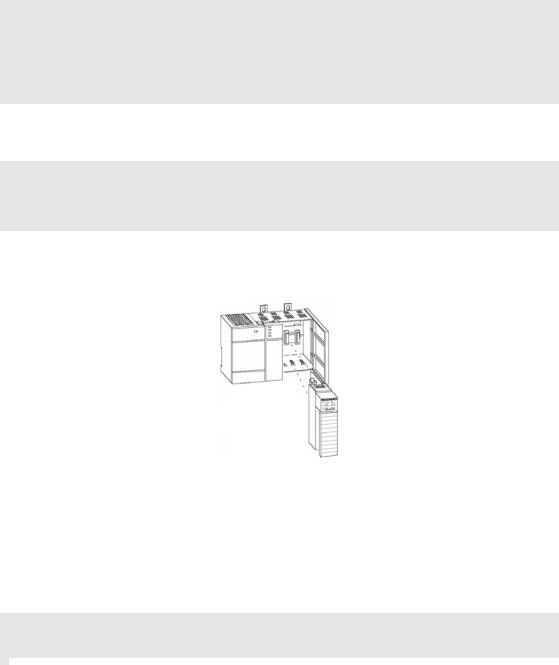
1.5Connecting Your PC to the Module
With the module securely mounted, connect your PC to the Configuration/Debug port using an RJ45-DB-9 Serial Adapter Cable and a Null Modem Cable.
1 Attach both cables as shown.
2 Insert the RJ45 cable connector into the Configuration/Debug port of the module.
3 Attach the other end to the serial port on your PC.
Page 16 of 108 |
ProSoft Technology, Inc. |
|
March 29, 2011 |

MVI46-MCM ♦ SLC Platform |
Configuring the MVI46-MCM Module |
Modbus Communication Module |
User Manual |
|
|
2 Configuring the MVI46-MCM Module
In order for the MVI46-MCM module to function, a minimum amount of configuration data must be transferred to the module. The following table describes the configuration data that the module will require, depending on the operating modes to be supported.
Module Register |
Functional |
Name |
Description |
Address |
Modes |
|
|
|
Affected |
|
|
5000 to 5009 |
Data Transfer |
General |
This section of the configuration data |
|
|
Module |
contains the module configuration data |
|
|
Configuration |
that defines the data transfer between the |
|
|
|
module and the SLC processor. |
5010 to 5039 and |
Master and |
Port |
These sections define the characteristics |
5040 to 5069 |
Slave |
Configuration |
of each of the Modbus serial |
|
|
|
communication ports on the module. |
|
|
|
These parameters must be set correctly |
|
|
|
for proper module operation. |
5200 to 6199 and |
Master |
Master |
If the module’s Master Mode functionality |
6200 to 7199 |
|
Command List |
is to be supported on a port, the Master |
|
|
|
Command List must be set up. |
Refer to the Installing and Configuring the Module section for a description of the configuration of the module. The MVI46-MCM module must be configured at least once when the card is first powered, and any time thereafter when the parameters must be changed.
2.1Configuration Data
Configuration of the module is performed by filling in a user defined data table. In the example ladder logic, file N10 stores the general module configuration information. N11 stores the command list for port 1. N12 stores the command list for port 2. Each register in the files has an associated symbol and description to aid in filling in the data. Refer to MVI46-MCM Configuration Data for a list of items that must be configured for the module and their associated location in the M0 file.
ProSoft Technology, Inc. |
Page 17 of 108 |
March 29, 2011 |
|
Configuring the MVI46-MCM Module |
|
MVI46-MCM ♦ SLC Platform |
|||||
User Manual |
|
|
|
Modbus Communication Module |
|||
|
|
|
|
|
|
|
|
|
Backplane Setup |
|
|
|
|
|
|
|
|
|
|
|
|
|
|
|
File |
M0 Offset |
Register |
Content |
Description |
||
|
|
|
|
|
|
|
|
|
N10:0 |
1 |
5000 |
Write Start Reg |
Not used in this version of the software |
|
|
|
N10:1 |
2 |
5001 |
Write Reg Count |
Not used in this version of the software |
||
|
|
|
|
|
|
|
|
|
N10:2 |
3 |
5002 |
Read Start Reg |
Not used in this version of the software |
||
|
|
|
|
|
|
|
|
|
N10:3 |
4 |
5003 |
Read Reg Count |
Not used in this version of the software |
||
|
|
|
|
|
|
|
|
|
N10:4 |
5 |
5004 |
Backplane Fail |
Not used in this version of the software |
|
|
|
N10:5 |
6 |
5005 |
Error Status Pointer |
This parameter specifies the register location in the |
||
|
|
|
|
|
module's database where module status data is |
||
|
|
|
|
|
stored. If a value less than 0 is entered, the data will |
||
|
|
|
|
|
not be stored in the database. If the value specified |
||
|
|
|
|
|
is in the range of 0 to 4940, the data is placed in the |
||
|
|
|
|
|
user data area. |
||
|
N10:6 |
7 |
5006 |
Spare |
|
|
|
|
|
|
|
|
|
|
|
|
N10:7 |
8 |
5007 |
Spare |
|
|
|
|
|
|
|
|
|
|
|
|
N10:8 |
9 |
5008 |
Spare |
|
|
|
|
N10:9 |
10 |
5009 |
Spare |
|
|
|
|
|
|
|
|
|
|
|
|
Port 1 Setup |
|
|
|
|
|
|
|
|
|
|
|
|
|
|
|
File |
M0 Offset |
Register |
Content |
Description |
||
|
|
|
|
|
|
|
|
|
N10:10 |
11 |
5010 |
Enable |
This parameter defines if this port will be used. If |
||
|
|
|
|
|
the parameter is set to 0, the port is disabled. A |
||
|
|
|
|
|
value of 1 enables the port. |
|
|
|
N10:11 |
12 |
5011 |
Type |
This parameter defines if the port emulates a |
||
|
|
|
|
|
master or slave device. Enter 0 to emulate a master |
||
|
|
|
|
|
device and 1 to emulate a slave device. |
|
|
|
N10:12 |
13 |
5012 |
Float Flag |
This flag specifies if the floating-point data access |
||
|
|
|
|
|
functionality is to be used. If the float flag is set to |
||
|
|
|
|
|
Y, Modbus functions 3,6, and 16 will interpret |
||
|
|
|
|
|
floating point values for registers as specified by |
||
|
|
|
|
|
the two following parameters. |
|
|
|
N10:13 |
14 |
5013 |
Float Start |
This parameter defines the first register of floating- |
||
|
|
|
|
|
point data. All requests with register values greater |
||
|
|
|
|
|
than or equal to this value will be considered |
||
|
|
|
|
|
floating-point data requests. This parameter is only |
||
|
|
|
|
|
used if the Float Flag is enabled. For example, if a |
||
|
|
|
|
|
value of 7000 is entered, all requests for registers |
||
|
|
|
|
|
7000 and above will be considered floating-point |
||
|
|
|
|
|
data. |
|
|
|
N10:14 |
15 |
5014 |
Float Offset |
This parameter defines the start register for |
||
|
|
|
|
|
floating-point data in the internal database. This |
||
|
|
|
|
|
parameter is only used if the Float Flag is enabled. |
||
|
|
|
|
|
For example, if the Float Offset value is set to 3000 |
||
|
|
|
|
|
and the float start parameter is set to 7000, data |
||
|
|
|
|
|
requests for register 7000 will use the internal |
||
|
|
|
|
|
Modbus register 3000. |
|
|
|
N10:15 |
16 |
5015 |
Protocol |
0=RTU, 1=ASCII |
||
|
|
|
|
|
|
|
|
Page 18 of 108 |
ProSoft Technology, Inc. |
|
March 29, 2011 |

MVI46-MCM ♦ SLC Platform |
|
|
Configuring the MVI46-MCM Module |
|||
Modbus Communication Module |
|
User Manual |
||||
|
|
|
|
|
|
|
|
|
|
|
|
|
|
|
File |
M0 Offset |
Register |
Content |
Description |
|
|
|
|
|
|
|
|
|
N10:16 |
17 |
5016 |
Baud Rate |
This is the baud rate to be used on the port. Enter |
|
|
|
|
|
|
the baud rate as a value. For example, to select |
|
|
|
|
|
|
19K baud, enter 19200. Exceptions: 38400 baud, |
|
|
|
|
|
|
enter 384. 57600 enter 576. 115000 enter 115. |
|
|
N10:17 |
18 |
5017 |
Parity |
This is the parity code to be used on the port. The |
|
|
|
|
|
|
coded values are as follows: |
|
|
|
|
|
|
0=None |
|
|
|
|
|
|
1=Odd |
|
|
|
|
|
|
2=Even |
|
|
|
|
|
|
|
|
|
N10:18 |
19 |
5018 |
Data Bits |
This parameter sets the number of data bits for |
|
|
|
|
|
|
each word used by the protocol. Enter a value in |
|
|
|
|
|
|
the range of 5 to 8. |
|
|
N10:19 |
20 |
5019 |
Stop Bits |
This parameter sets the number of stop bits for |
|
|
|
|
|
|
each data value sent. Enter a value of 1 or 2. |
|
|
N10:20 |
21 |
5020 |
RTS On Delay |
This parameter sets the number of milliseconds to |
|
|
|
|
|
|
delay after RTS is asserted before the data will be |
|
|
|
|
|
|
transmitted. Enter a value in the range of 0 to |
|
|
|
|
|
|
65535. |
|
|
N10:21 |
22 |
5021 |
RTS Off Delay |
This parameter sets the number of milliseconds to |
|
|
|
|
|
|
delay after the last byte of data is sent before the |
|
|
|
|
|
|
RTS modem signal will be set low. Enter a value in |
|
|
|
|
|
|
the range of 0 to 65535. |
|
|
N10:22 |
23 |
5022 |
Minimum Response |
This parameter sets the number of milliseconds to |
|
|
|
|
|
Delay |
wait before a response message is sent out of the |
|
|
|
|
|
|
port. This parameter is required when interfacing to |
|
|
|
|
|
|
a slow responding device. Enter a value in the |
|
|
|
|
|
|
range of 0 to 65535. |
|
|
N10:23 |
24 |
5023 |
Use CTS Line |
This parameter specifies if the CTS modem control |
|
|
|
|
|
|
line is to be used. If the parameter is set to 0, the |
|
|
|
|
|
|
CTS line will not be monitored. If the parameter is |
|
|
|
|
|
|
set to 1, the CTS line will be monitored and must be |
|
|
|
|
|
|
high before the module will send data. Normally, |
|
|
|
|
|
|
this parameter is required when half-duplex |
|
|
|
|
|
|
modems are used for communication (2-wire). |
|
|
N10:24 |
25 |
5024 |
Slave ID |
This parameter defines the virtual Modbus slave |
|
|
|
|
|
|
address for the internal database. Any requests |
|
|
|
|
|
|
received by the port with this address will be |
|
|
|
|
|
|
processed by the module. Verify that each device |
|
|
|
|
|
|
has a unique address on the network. |
|
|
N10:25 |
26 |
5025 |
Bit Input Offset |
This parameter specifies the offset address in the |
|
|
|
|
|
|
internal Modbus database for network requests for |
|
|
|
|
|
|
Modbus function 2 commands. For example, if the |
|
|
|
|
|
|
value is set to 150, an address request of 0 will |
|
|
|
|
|
|
return the value at register 150 in the database. |
|
|
N10:26 |
27 |
5026 |
Word Input Offset |
This parameter specifies the offset address in the |
|
|
|
|
|
|
internal Modbus database for network requests for |
|
|
|
|
|
|
Modbus function 4 commands. For example, if the |
|
value is set to 150, an address request of 0 will return the value at register 150 in the database.
ProSoft Technology, Inc. |
Page 19 of 108 |
March 29, 2011 |
|
Configuring the MVI46-MCM Module |
|
MVI46-MCM ♦ SLC Platform |
||||
User Manual |
|
|
|
Modbus Communication Module |
||
|
|
|
|
|
|
|
|
|
|
|
|
|
|
|
File |
M0 Offset |
Register |
Content |
Description |
|
|
|
|
|
|
|
|
|
N10:27 |
28 |
5027 |
Output Offset |
This parameter specifies the offset address in the |
|
|
|
|
|
|
internal Modbus database for network requests for |
|
|
|
|
|
|
Modbus function 1, 5, or 15 commands. For |
|
|
|
|
|
|
example, if the value is set to 100, an address |
|
|
|
|
|
|
request of 0 will return the value at register 100 in |
|
|
|
|
|
|
the database. |
|
|
N10:28 |
29 |
5028 |
Holding Register |
This parameter specifies the offset address in the |
|
|
|
|
|
Offset |
internal Modbus database for network requests for |
|
|
|
|
|
|
Modbus 3, 6, or 16 commands. For example, if the |
|
|
|
|
|
|
value is set to 50, an address request of 0 will |
|
|
|
|
|
|
return the value at register 50 in the database. |
|
|
N10:29 |
30 |
5029 |
Command Count |
This parameter specifies the number of commands |
|
|
|
|
|
|
to be processed for the port. Enter a value of 0 to |
|
|
|
|
|
|
100. |
|
|
N10:30 |
31 |
5030 |
Minimum Command |
This parameter specifies the number of |
|
|
|
|
|
Delay |
milliseconds to wait between the initial issuance of |
|
|
|
|
|
|
a command. This parameter can be used to delay |
|
|
|
|
|
|
all commands sent to slaves to avoid "flooding" |
|
|
|
|
|
|
commands on the network. This parameter does |
|
|
|
|
|
|
not affect retries of a command as they will be |
|
|
|
|
|
|
issued when failure is recognized. Enter a value in |
|
|
|
|
|
|
the range of 0 to 65535. |
|
|
N10:31 |
32 |
5031 |
Command Error |
This parameter sets the address in the internal |
|
|
|
|
|
Pointer |
Modbus database where the command error data |
|
|
|
|
|
|
will be placed. If the value is set to -1, the data will |
|
|
|
|
|
|
not be transferred to the database. Enter a value of |
|
|
|
|
|
|
0 to 4999. |
|
|
N10:32 |
33 |
5032 |
Response Timeout |
This parameter represents the message response |
|
|
|
|
|
|
timeout period in 1 ms increments. This is the time |
|
|
|
|
|
|
that a port configured as a master will wait before |
|
|
|
|
|
|
re-transmitting a command if no response is |
|
|
|
|
|
|
received from the addressed slave. The value is set |
|
|
|
|
|
|
depending on to communication network used and |
|
|
|
|
|
|
the expected response time of the slowest device |
|
|
|
|
|
|
on the network. |
|
|
N10:33 |
34 |
5033 |
Retry Count |
This parameter specifies the number of times a |
|
|
|
|
|
|
command will be retried if it fails. Enter a value in |
|
|
|
|
|
|
the range of 0 to 10. |
|
|
N10:34 |
35 |
5034 |
Error Delay Count |
This parameter specifies the number of polls to be |
|
|
|
|
|
|
skipped on the slave before trying to re-establish |
|
|
|
|
|
|
communications. After the slave fails to respond, |
|
|
|
|
|
|
the master will skip commands to be sent to the |
|
|
|
|
|
|
slave the number of times entered in the |
|
|
|
|
|
|
parameter. Enter a value in the range of 0 to |
|
|
|
|
|
|
65535. |
|
|
N10:35 |
36 |
5035 |
Reserved |
|
|
|
|
|
|
|
|
|
|
N10:36 |
37 |
5036 |
Use Guard Band |
Use packet gap timeout for messages (Yes or No). |
|
|
|
|
|
Timer |
Use only in multi-drop applications. |
|
|
N10:37 |
38 |
5037 |
Guard Band Timeout |
A value of 0 uses the default baud rate or you can |
|
|
|
|
|
|
set a value in milliseconds (0 to 65535) |
|
|
N10:38 |
39 |
5038 |
Spare |
|
|
|
|
|
|
|
|
|
|
N10:39 |
40 |
5039 |
Spare |
|
|
|
|
|
|
|
|
|
|
|
|
|
|
|
|
Page 20 of 108 |
|
|
|
ProSoft Technology, Inc. |
||
|
|
|
|
|
March 29, 2011 |
|
MVI46-MCM ♦ SLC Platform |
|
|
Configuring the MVI46-MCM Module |
|||
Modbus Communication Module |
|
|
User Manual |
|||
|
|
|
|
|
|
|
|
Port 2 Setup |
|
|
|
|
|
|
|
|
|
|
|
|
|
File |
M0 Offset |
Register |
Content |
Description |
|
|
|
|
|
|
|
|
|
N10:40 |
41 |
5040 |
Enable |
This parameter defines if this port will be used. If the |
|
|
|
|
|
|
parameter is set to 0, the port is disabled. A value of 1 |
|
|
|
|
|
|
enables the port. |
|
|
N10:41 |
42 |
5041 |
Type |
This parameter defines if the port emulates a master or |
|
|
|
|
|
|
slave device. Enter 0 to emulate a master device and 1 |
|
|
|
|
|
|
to emulate a slave device. |
|
|
N10:42 |
43 |
5042 |
Float Flag |
This flag specifies if the floating-point data access |
|
|
|
|
|
|
functionality is to be used. If the float flag is set to Y, |
|
|
|
|
|
|
Modbus functions 3,6, and 16 will interpret floating point |
|
|
|
|
|
|
values for registers as specified by the two following |
|
|
|
|
|
|
parameters. |
|
|
N10:43 |
44 |
5043 |
Float Start |
This parameter defines the first register of floating-point |
|
|
|
|
|
|
data. All requests with register values greater than or |
|
|
|
|
|
|
equal to this value will be considered floating-point data |
|
|
|
|
|
|
requests. This parameter is only used if the Float Flag |
|
|
|
|
|
|
is enabled. For example, if a value of 7000 is entered, |
|
|
|
|
|
|
all requests for registers 7000 and above will be |
|
|
|
|
|
|
considered floating-point data. |
|
|
N10:44 |
45 |
5044 |
Float Offset |
This parameter defines the start register for floating- |
|
|
|
|
|
|
point data in the internal database. This parameter is |
|
|
|
|
|
|
only used if the Float Flag is enabled. For example, if |
|
|
|
|
|
|
the Float Offset value is set to 3000 and the float start |
|
|
|
|
|
|
parameter is set to 7000, data requests for register |
|
|
|
|
|
|
7000 will use the internal Modbus register 3000. |
|
|
N10:45 |
46 |
5045 |
Protocol |
0=RTU, 1=ASCII |
|
|
|
|
|
|
|
|
|
N10:46 |
47 |
5046 |
Baud Rate |
This is the baud rate to be used on the port. Enter the |
|
|
|
|
|
|
baud rate as a value. For example, to select 19K baud, |
|
|
|
|
|
|
enter 19200. Exceptions: 38400 baud, enter 384. 57600 |
|
|
|
|
|
|
enter 576. 115000 enter 115. |
|
|
N10:47 |
48 |
5047 |
Parity |
This is the parity code to be used on the port. The |
|
|
|
|
|
|
coded values are as follows: |
|
|
|
|
|
|
0=None |
|
|
|
|
|
|
1=Odd |
|
|
|
|
|
|
2=Even |
|
|
|
|
|
|
|
|
|
N10:48 |
49 |
5048 |
Data Bits |
This parameter sets the number of data bits for each |
|
|
|
|
|
|
word used by the protocol. Enter a value in the range of |
|
|
|
|
|
|
5 to 8. |
|
|
N10:49 |
50 |
5049 |
Stop Bits |
This parameter sets the number of stop bits for each |
|
|
|
|
|
|
data value sent. Enter a value of 1 or 2. |
|
|
N10:50 |
51 |
5050 |
RTS On Delay |
This parameter sets the number of milliseconds to |
|
|
|
|
|
|
delay after RTS is asserted before the data will be |
|
|
|
|
|
|
transmitted. Enter a value in the range of 0 to 65535. |
|
|
N10:51 |
52 |
5051 |
RTS Off Delay |
This parameter sets the number of milliseconds to |
|
|
|
|
|
|
delay after the last byte of data is sent before the RTS |
|
modem signal will be set low. Enter a value in the range of 0 to 65535.
ProSoft Technology, Inc. |
Page 21 of 108 |
March 29, 2011 |
|
Configuring the MVI46-MCM Module |
|
MVI46-MCM ♦ SLC Platform |
||||
User Manual |
|
|
|
Modbus Communication Module |
||
|
|
|
|
|
|
|
|
|
|
|
|
|
|
|
File |
M0 Offset |
Register |
Content |
Description |
|
|
|
|
|
|
|
|
|
N10:52 |
53 |
5052 |
Minimum |
This parameter sets the number of milliseconds to wait |
|
|
|
|
|
Response Delay |
before a response message is sent out of the port. This |
|
|
|
|
|
|
parameter is required when interfacing to a slow |
|
|
|
|
|
|
responding device. Enter a value in the range of 0 to |
|
|
|
|
|
|
65535. |
|
|
N10:53 |
54 |
5053 |
Use CTS Line |
This parameter specifies if the CTS modem control line |
|
|
|
|
|
|
is to be used. If the parameter is set to 0, the CTS line |
|
|
|
|
|
|
will not be monitored. If the parameter is set to 1, the |
|
|
|
|
|
|
CTS line will be monitored and must be high before the |
|
|
|
|
|
|
module will send data. Normally, this parameter is |
|
|
|
|
|
|
required when half-duplex modems are used for |
|
|
|
|
|
|
communication (2-wire). |
|
|
N10:54 |
55 |
5054 |
Slave ID |
This parameter defines the virtual Modbus slave |
|
|
|
|
|
|
address for the internal database. Any requests |
|
|
|
|
|
|
received by the port with this address will be processed |
|
|
|
|
|
|
by the module. Verify that each device has a unique |
|
|
|
|
|
|
address on the network. |
|
|
N10:55 |
56 |
5055 |
Bit Input Offset |
This parameter specifies the offset address in the |
|
|
|
|
|
|
internal Modbus database for network requests for |
|
|
|
|
|
|
Modbus function 2 commands. For example, if the |
|
|
|
|
|
|
value is set to 150, an address request of 0 will return |
|
|
|
|
|
|
the value at register 150 in the database. |
|
|
N10:56 |
57 |
5056 |
Word Input Offset |
This parameter specifies the offset address in the |
|
|
|
|
|
|
internal Modbus database for network requests for |
|
|
|
|
|
|
Modbus function 4 commands. For example, if the |
|
|
|
|
|
|
value is set to 150, an address request of 0 will return |
|
|
|
|
|
|
the value at register 150 in the database. |
|
|
N10:57 |
58 |
5057 |
Output Offset |
This parameter specifies the offset address in the |
|
|
|
|
|
|
internal Modbus database for network requests for |
|
|
|
|
|
|
Modbus function 1, 5, or 15 commands. For example, if |
|
|
|
|
|
|
the value is set to 100, an address request of 0 will |
|
|
|
|
|
|
return the value at register 100 in the database. |
|
|
N10:58 |
59 |
5058 |
Holding Register |
This parameter specifies the offset address in the |
|
|
|
|
|
Offset |
internal Modbus database for network requests for |
|
|
|
|
|
|
Modbus 3, 6, or 16 commands. For example, if the |
|
|
|
|
|
|
value is set to 50, an address request of 0 will return |
|
|
|
|
|
|
the value at register 50 in the database. |
|
|
N10:59 |
60 |
5059 |
Command Count |
This parameter specifies the number of commands to |
|
|
|
|
|
|
be processed for the port. Enter a value of 0 to 100. |
|
|
N10:60 |
61 |
5060 |
Minimum |
This parameter specifies the number of milliseconds to |
|
|
|
|
|
Command Delay |
wait between the initial issuance of a command. This |
|
|
|
|
|
|
parameter can be used to delay all commands sent to |
|
|
|
|
|
|
slaves to avoid "flooding" commands on the network. |
|
|
|
|
|
|
This parameter does not affect retries of a command as |
|
|
|
|
|
|
they will be issued when failure is recognized. Enter a |
|
|
|
|
|
|
value in the range of 0 to 65535. |
|
|
N10:61 |
62 |
5061 |
Command Error |
This parameter sets the address in the internal Modbus |
|
|
|
|
|
Pointer |
database where the command error data will be placed. |
|
|
|
|
|
|
If the value is set to -1, the data will not be transferred |
|
|
|
|
|
|
to the database. Enter a value of 0 to 4999. |
|
Page 22 of 108 |
ProSoft Technology, Inc. |
|
March 29, 2011 |
MVI46-MCM ♦ SLC Platform |
|
|
Configuring the MVI46-MCM Module |
|||
Modbus Communication Module |
|
|
User Manual |
|||
|
|
|
|
|
|
|
|
|
|
|
|
|
|
|
File |
M0 Offset |
Register |
Content |
Description |
|
|
|
|
|
|
|
|
|
N10:62 |
63 |
5062 |
Response |
This parameter represents the message response |
|
|
|
|
|
Timeout |
timeout period in 1 ms increments. This is the time that |
|
|
|
|
|
|
a port configured as a master will wait before re- |
|
|
|
|
|
|
transmitting a command if no response is received from |
|
|
|
|
|
|
the addressed slave. The value is set depending on to |
|
|
|
|
|
|
communication network used and the expected |
|
|
|
|
|
|
response time of the slowest device on the network. |
|
|
N10:63 |
64 |
5063 |
Retry Count |
This parameter specifies the number of times a |
|
|
|
|
|
|
command will be retried if it fails. Enter a value in the |
|
|
|
|
|
|
range of 0 to 10. |
|
|
N10:64 |
65 |
5064 |
Error Delay Count |
This parameter specifies the number of polls to be |
|
|
|
|
|
|
skipped on the slave before trying to re-establish |
|
|
|
|
|
|
communications. After the slave fails to respond, the |
|
|
|
|
|
|
master will skip commands to be sent to the slave the |
|
|
|
|
|
|
number of times entered in the parameter. Enter a |
|
|
|
|
|
|
value in the range of 0 to 65535. |
|
|
N10:65 |
66 |
5065 |
Reserved |
|
|
|
|
|
|
|
|
|
|
N10:66 |
67 |
5066 |
Use Guard Band |
Use packet gap timeout for messages (Yes or No). Use |
|
|
|
|
|
Timer |
only in multi-drop applications. |
|
|
N10:67 |
68 |
5067 |
Guard Band |
A value of 0 uses the default baud rate or you can set a |
|
|
|
|
|
Timeout |
timeout value in milliseconds (0 to 65535). |
|
|
N10:68 |
69 |
5068 |
Spare |
|
|
|
|
|
|
|
|
|
|
N10:69 |
70 |
5069 |
Spare |
|
|
|
|
|
|
|
|
|
Guard Band parameters
With multiple nodes in the network (multidrop), the module must be able to define the time period used to properly recognize the received data sequence as a valid Modbus message. This time period is defined through the guardband timer parameter. Failure to set the Guard Band functionality may cause successive communication errors in the Modbus network.
This functionality is only used for Modbus RTU mode, when the module is configured as a slave device in a multidrop network (RS-422 or RS-485 wiring). In RTU mode, when the module receives sequence of data from another node, it will recognize the end of the message when it detects a 3.5 character gap. The next byte received after a 3.5 character gap will be recognized as the start of a new Modbus message.
The 3.5 character gap depends on the port communication settings, especially the baud rate. The higher the baud rate, the lower the corresponding time period equivalent to the 3.5 character delay.
ProSoft Technology, Inc. |
Page 23 of 108 |
March 29, 2011 |
|

Configuring the MVI46-MCM Module |
MVI46-MCM ♦ SLC Platform |
User Manual |
Modbus Communication Module |
|
|
To enable the Guard Band Timeout parameter:
1First of all, enable the functionality through the Use Guard Band Timer parameter as follows:
Use Guard Band Timer = Y
2 Then, set the Guard Band Timeout as follows:
Guard Band Timeout = 0
This configuration will set the module to use a pre-defined time interval for Modbus message recognition calculated for each baud rate. This should provide optimal performance for most applications.
The following guard band timer values will be automatically used by the module with the default parameter value (Guard Band Timeout = 0) is selected:
Baud |
Guard Band Timer (ms) |
110 |
350 |
150 |
256 |
300 |
128 |
|
|
600 |
64 |
|
|
1200 |
32 |
2400 |
16 |
4800 |
8 |
9600 |
4 |
|
|
19200 |
2 |
|
|
28800 |
2 |
38400 |
2 |
57600 |
1 |
115200 |
1 |
|
|
If you still observe a considerable number of communication errors, try to increase the Guard Band Timeout value (in milliseconds) until the network performance is improved.
Page 24 of 108 |
ProSoft Technology, Inc. |
|
March 29, 2011 |
MVI46-MCM ♦ SLC Platform |
|
|
|
Configuring the MVI46-MCM Module |
|||||
Modbus Communication Module |
|
|
|
User Manual |
|||||
|
|
|
|
|
|
|
|
|
|
|
|
Port 1 Commands |
|
|
|
|
|
|
|
|
|
|
|
|
|
|
|
|
|
|
|
File |
M0 Offset |
Register |
Content |
Description |
|||
|
|
|
|
|
|
|
|
|
|
|
|
N11:0 to |
71 to 80 |
5200 to 5209 |
Command #1 |
This set of registers contains the parameters for the |
|||
|
|
N11:09 |
|
|
|
|
first command in the master command list. Refer to |
||
|
|
|
|
|
|
|
the data object section of the documentation. |
|
|
|
|
N11:10 to |
81 to 90 |
5210 to 5219 |
Command #2 |
Command #2 dataset |
|||
|
|
N11:19 |
|
|
|
|
|
|
|
|
|
|
1061 to 1070 |
6190 to 6199 |
Command #100 |
Command #100 dataset |
|||
|
|
|
|
|
|
|
|
|
|
|
|
Port 2 Commands |
|
|
|
|
|
|
|
|
|
|
|
|
|
|
|
|
|
|
|
File |
M0 Offset |
Register |
|
Content |
Description |
||
|
|
|
|
|
|
|
|
|
|
|
|
N12:0 to |
1071 to 1080 |
6200 to 6209 |
Command #1 |
This set of registers contains the parameters for the |
|||
|
|
N12:09 |
|
|
|
|
first command in the master command list. Refer to |
||
|
|
|
|
|
|
|
the data object section of the documentation. |
|
|
|
|
N12:10 to |
1081 to 1090 |
6210 to 6219 |
Command #2 |
Command #2 dataset |
|||
|
|
N12:19 |
|
|
|
|
|
|
|
|
|
|
2061 to 2070 |
7190 to 7199 |
Command #100 |
Command #100 dataset |
|||
|
|
|
|
|
|
|
|
|
|
|
|
Command Control |
|
|
|
|
|
|
|
|
|
|
|
|
|
|
|
|
|
|
|
Register |
Content |
|
Description |
|
|
|
|
|
|
|
|
|
|||||
7800 |
Command Code |
Enter one of the valid control command codes in this register to control the |
|||||||
|
|
|
|
|
module (9997, 9998, or 9999). Refer to Command Control (page 69, page 25, |
||||
|
|
|
|
|
page 64) for more information. |
||||
|
|
7801 to 7999 Command Data |
Reserved for future use. |
|
|
|
|||
|
|
|
|
|
|
|
|
|
|
ProSoft Technology, Inc. |
Page 25 of 108 |
March 29, 2011 |
|
Configuring the MVI46-MCM Module |
MVI46-MCM ♦ SLC Platform |
User Manual |
Modbus Communication Module |
|
|
Page 26 of 108 |
ProSoft Technology, Inc. |
|
March 29, 2011 |
MVI46-MCM ♦ SLC Platform |
Ladder Logic |
Modbus Communication Module |
User Manual |
|
|
3 Ladder Logic |
|
|
In This Chapter |
|
|
|
Module Data .......................................................................................... |
28 |
|
Adding the Module to an Existing Project.............................................. |
31 |
Ladder logic is required for application of the MVI46-MCM module. Tasks that must be handled by the ladder logic are module data transfer, special block handling, and status data receipt. Additionally, a power-up handler may be needed to handle the initialization of the module’s data and to clear any processor fault conditions.
The sample ladder logic, on the ProSoft Solutions CD-ROM, is extensively commented, to provide information on the purpose and function of each rung. For most applications, the sample ladder will work without modification.
ProSoft Technology, Inc. |
Page 27 of 108 |
March 29, 2011 |
|
Ladder Logic |
MVI46-MCM ♦ SLC Platform |
User Manual |
Modbus Communication Module |
|
|
3.1Module Data
All data related to the MVI46-MCM module is stored in user defined data areas. The user is responsible for setting up the data areas to match the specific application for which the module is used. Each data area is discussed in the following topics.
3.1.1 Backplane Parameters
In this revision of the module, all data to be transferred between the SLC processor and the module is held in the module's M1 file. This simplifies the ladder logic. In order to read data in the module, copy the specific data area in the M1 file into a user defined file. Repeat this operation for each data area. Remember, the maximum data area that can be copied with the COP instruction is 128 words. In order to write data to the module, copy the data in the user defined file to the specific data area in the M1 file. The read and write data operations should be limited to the M1 words 0 to 4999. The modules status data can be read from the M1 file starting at register 7200.
Only one parameter is used in this section of the configuration.
The Error Status Pointer parameter defines the location in the module's database where the error/status data is stored. If the value is set to -1, the data will not be stored in the user data area. A value between 0 and 4939 will cause the module's program to store the data at the specified location.
3.1.2 Port Parameters
These parameters define the operation of each of the Modbus ports on the module. Refer to MVI46-MCM Configuration Data Definition for a definition of each parameter.
Page 28 of 108 |
ProSoft Technology, Inc. |
|
March 29, 2011 |

MVI46-MCM ♦ SLC Platform |
Ladder Logic |
Modbus Communication Module |
User Manual |
|
|
3.1.3 Master Commands
These records define the commands in the master command list. Each parameter is described in the following table.
Parameter |
Description |
Enable |
This parameter defines if the command is executed or disregarded. The |
|
following values are valid: 0=Disables the command and it will not |
|
execute. 1=The command will be considered for execution each scan of |
|
the command list and will be controlled by the PollInt parameter. And |
|
2=The command will only execute if the data associated with the |
|
command has changed since the command was last issued. This option |
|
is only available for write commands. |
IntAddress |
This parameter specifies the starting internal register address to be |
|
associated with the command. Valid entry for this parameter is 0 to 4999 |
|
for Register Address (0 to 65535 for Bit Address). |
Polllnt |
This parameter defines the minimum number of seconds to wait between |
|
the execution of continuous commands (Enable=1). This poll interval |
|
command can be used to lighten the communications load on a busy |
|
network. Valid entry for this parameter is 0 to 65535. |
Count |
This parameter defines the number of registers to be considered by the |
|
command. Valid entry for this parameter depends on the Modbus |
|
specification for the command. |
Swap |
This parameter specifies if the data used in the command must be |
|
altered when a Modbus function code 3 reads data from a node on the |
|
network. Values that can be assigned are as follows: 0=no swapping of |
|
data, 1=swap word values, 2=swap word and byte values and 3=swap |
|
byte values. This option is used when interfacing the module with ASCII |
|
and floating-point data on other devices. |
Node |
This parameter assigns the Modbus slave node address for the module |
|
to reach with the command on the Modbus network. This parameter can |
|
be assigned values from 0 to 255. Most Modbus networks limit the upper |
|
value to 247. |
Func |
This parameter specifies the Modbus function to be performed by the |
|
command. Valid entries are 1, 2, 3, 4, 5, 6, 15 and 16. |
DevAddress |
This parameter defines the starting address in the device being |
|
considered by the command. Values entered in this field are dependent |
|
on the node’s database definition. Refer to the specific manufacture’s |
|
database definition for the device to determine the location of the data to |
|
be interfaced. |
3.1.4 Status Data
This data area views the status of the module. Use this data to monitor the state of the module at a "real-time rate". Refer to the MVI46-MCM Status Data Definition (page 82) for a complete listing of the data stored in this object. This data can be read from the module’s M1 file starting at register 7200. User data file N30 is defined in the example ladder logic for this purpose.
ProSoft Technology, Inc. |
Page 29 of 108 |
March 29, 2011 |
|
Ladder Logic |
MVI46-MCM ♦ SLC Platform |
User Manual |
Modbus Communication Module |
|
|
3.1.5 User Data
All user data is stored in the module’s M1 file in registers 0 to 4999. This 5000word area is directly accessible from the ladder logic. The COP instruction should be used to move blocks of data between the user data files and the module’s M1 file. This limits the number of accesses to the M1 data area and provides faster system response. In the example ladder logic, N31 holds data read from the module, and N32 stores data to write to the module.
3.1.6 Slave Polling Control and Status
Two data areas can be allocated in the SLC to hold the polling status of each slave on the master ports. This status data can be used to determine which slaves are currently active on the port, are in communications error, or have their polling suspended and disabled. If the configuration supplies an address where this data resides, copy the data from the M1 file to the reserved files in the SLC. Using special blocks, the processor can enable or disable the polling of selected slaves.
Page 30 of 108 |
ProSoft Technology, Inc. |
|
March 29, 2011 |
 Loading...