


 Loading...
MVI71-MNET
PLC Platform
Modbus TCP/IP Interface Module
June 23, 2009
USER MANUAL
MVI (Multi Vendor Interface) Modules
WARNING - EXPLOSION HAZARD - DO NOT DISCONNECT EQUIPMENT UNLESS POWER HAS BEEN SWITCHED OFF OR THE AREA IS KNOWN TO BE NON-HAZARDOUS.
AVERTISSEMENT - RISQUE D'EXPLOSION - AVANT DE DÉCONNECTER L'EQUIPMENT, COUPER LE COURANT OU S'ASSURER QUE L'EMPLACEMENT EST DÉSIGNÉ NON DANGEREUX.
CL I Div 2 GPs A, B, C, D Temp Code T5
II 3 G
Ex nA IIC T5 X
0° C <= Ta <= 60° C
II - Equipment intended for above ground use (not for use in mines). 3 - Category 3 equipment, investigated for normal operation only. G - Equipment protected against explosive gasses.
Important Installation Instructions
Power, Input and Output (I/O) wiring must be in accordance with Class I, Division 2 wiring methods, Article 501-4 (b) of the National Electrical Code, NFPA 70 for installation in the U.S., or as specified in Section 18-1J2 of the Canadian Electrical Code for installations in Canada, and in accordance with the authority having jurisdiction. The following warnings must be heeded:
AWARNING - EXPLOSION HAZARD - SUBSTITUTION OF COMPONENTS MAY IMPAIR SUITABILITY FOR CLASS I, DIV. 2;
BWARNING - EXPLOSION HAZARD - WHEN IN HAZARDOUS LOCATIONS, TURN OFF POWER BEFORE REPLACING OR WIRING MODULES, and
CWARNING - EXPLOSION HAZARD - DO NOT DISCONNECT EQUIPMENT UNLESS POWER HAS BEEN SWITCHED OFF OR THE AREA IS KNOWN TO BE NONHAZARDOUS.
D"THIS DEVICE SHALL BE POWERED BY CLASS 2 OUTPUTS ONLY.
Warnings
North America Warnings
AWarning - Explosion Hazard - Substitution of components may impair suitability for Class I, Division 2.
BWarning - Explosion Hazard - When in Hazardous Locations, turn off power before replacing or rewiring modules.
Warning - Explosion Hazard - Do not disconnect equipment unless power has been switched off or the area is known to be nonhazardous.
CSuitable for use in Class I, division 2 Groups A, B, C and D Hazardous Locations or Non-Hazardous Locations.
ATEX Warnings and Conditions of Safe Usage:
Power, Input, and Output (I/O) wiring must be in accordance with the authority having jurisdiction
AWarning - Explosion Hazard - When in hazardous locations, turn off power before replacing or wiring modules.
BWarning - Explosion Hazard - Do not disconnect equipment unless power has been switched off or the area is known to be non-hazardous.
CThese products are intended to be mounted in an IP54 enclosure. The devices shall provide external means to prevent the rated voltage being exceeded by transient disturbances of more than 40%. This device must be used only with ATEX certified backplanes.
DDO NOT OPEN WHEN ENERGIZED.

Electrical Ratings
Backplane Current Load: 800 mA @ 5 V DC; 3mA @ 24V DC
Operating Temperature: 0 to 60°C (32 to 140°F)
Storage Temperature: -40 to 85°C (-40 to 185°F)
Shock: 30g Operational; 50g non-operational; Vibration: 5 g from 10 to 150 Hz
Relative Humidity 5% to 95% (non-condensing)
All phase conductor sizes must be at least 1.3 mm(squared) and all earth ground conductors must be at least 4mm(squared).
Markings
ANSI / ISA |
ISA 12.12.01 Class I Division 2, GPs A, B, C, D |
CSA/cUL |
C22.2 No. 213-1987 |
|
|
CSA CB Certified |
IEC61010 |
ATEX |
EN60079-0 Category 3, Zone 2 |
|
EN60079-15 |
243333
Warning: This module is not hot-swappable! Always remove power from the rack before inserting or removing this module, or damage may result to the module, the processor, or other connected devices.
Battery Life Advisory
All modules in the MVI series use a rechargeable Lithium Vanadium Pentoxide battery to backup the 512K SRAM memory, real-time clock, and CMOS. The battery should last for the life of the module.
The module must be powered for approximately twenty hours before it becomes fully charged. After it is fully charged, the battery provides backup power for the CMOS setup and configuration data, the real-time clock, and the 512K SRAM memory for approximately 21 days.
Before you remove a module from its power source, ensure that the battery within the module is fully charged. A fully charged battery will hold the BIOS settings (after being removed from its power source) for a limited number of days. When the battery is fully discharged, the module will revert to the default BIOS settings.
Note: The battery is not user replaceable.
Your Feedback Please
We always want you to feel that you made the right decision to use our products. If you have suggestions, comments, compliments or complaints about the product, documentation or support, please write or call us.
ProSoft Technology
5201 Truxtun Ave., 3rd Floor Bakersfield, CA 93309
+1 (661) 716-5100
+1 (661) 716-5101 (Fax) www.prosoft-technology.com
Copyright © ProSoft Technology, Inc. 2009. All Rights Reserved.
MVI71-MNET User Manual
June 23, 2009
ProSoft Technology ®, ProLinx ®, inRAx ®, ProTalk®, and RadioLinx ® are Registered Trademarks of ProSoft Technology, Inc. All other brand or product names are or may be trademarks of, and are used to identify products and services of, their respective owners.
ProSoft Technology® Product Documentation
In an effort to conserve paper, ProSoft Technology no longer includes printed manuals with our product shipments. User Manuals, Datasheets, Sample Ladder Files, and Configuration Files are provided on the enclosed CD, and are available at no charge from our web site: www.prosoft-technology.com
Printed documentation is available for purchase. Contact ProSoft Technology for pricing and availability.
Asia Pacific: +603.7724.2080
Europe, Middle East, Africa: +33 (0) 5.3436.87.20
Latin America: +1.281.298.9109
North America: +1.661.716.5100

Contents |
|
MVI71-MNET ♦ PLC Platform |
User Manual |
|
Modbus TCP/IP Interface Module |
Contents |
|
|
MVI (Multi Vendor Interface) Modules ................................................................................................ |
2 |
|
Important Installation Instructions ....................................................................................................... |
2 |
|
Warnings ............................................................................................................................................. |
2 |
|
Battery Life Advisory ........................................................................................................................... |
3 |
|
Your Feedback Please........................................................................................................................ |
3 |
|
ProSoft Technology® Product Documentation................................................................................... |
4 |
|
Guide to the MVI71-MNET User Manual |
7 |
|
1 |
Start Here |
9 |
1.1 |
System Requirements ............................................................................................... |
9 |
1.2 |
Package Contents ................................................................................................... |
10 |
1.3 |
Install ProSoft Configuration Builder Software........................................................ |
11 |
1.4 |
Setting Jumpers ...................................................................................................... |
12 |
1.5 |
Install the Module in the Rack ................................................................................. |
12 |
1.6 |
Connect your PC to the Processor.......................................................................... |
14 |
1.7 |
Download the Sample Program to the Processor................................................... |
15 |
1.8 |
Connect your PC to the Module .............................................................................. |
18 |
2 |
Module Configuration |
19 |
2.1 |
Installing and Configuring the Module..................................................................... |
19 |
2.2 |
Module Data ............................................................................................................ |
22 |
2.3 |
Status Data.............................................................................................................. |
22 |
2.4 |
User Data ................................................................................................................ |
22 |
2.5 |
Event Command Data............................................................................................. |
23 |
2.6 |
Modbus Message Data ........................................................................................... |
23 |
2.7 |
ProSoft Configuration Builder.................................................................................. |
23 |
2.8 |
Download the Project to the Module ....................................................................... |
40 |
3 |
Ladder Logic |
41 |
4 |
Diagnostics and Troubleshooting |
43 |
4.1 |
Reading Status Data from the Module.................................................................... |
43 |
4.2 |
LED Status Indicators.............................................................................................. |
53 |
5 |
Reference |
57 |
5.1 |
Product Specifications............................................................................................. |
57 |
5.2 |
Functional Overview................................................................................................ |
59 |
5.3 |
Cable Connections .................................................................................................. |
78 |
5.4 |
MVI71-MNET Status Data Definition for Side Connect File.................................... |
82 |
5.5 |
Status Data Structure for Database Storage........................................................... |
83 |
5.6 |
Client Error/Status Data .......................................................................................... |
85 |
ProSoft Technology, Inc. |
Page 5 of 109 |
|
June 23, 2009 |
|
|

MVI71-MNET ♦ PLC Platform |
Contents |
|
Modbus TCP/IP Interface Module |
User Manual |
|
5.7 |
Modbus Protocol Specification ............................................................................... |
88 |
6 |
Support, Service & Warranty |
99 |
6.1 |
How to Contact Us: Technical Support................................................................... |
99 |
6.2 |
Return Material Authorization (RMA) Policies and Conditions ............................. |
100 |
6.3 |
LIMITED WARRANTY .......................................................................................... |
101 |
Index |
107 |
|
Page 6 of 109 |
ProSoft Technology, Inc. |
|
June 23, 2009 |

Start Here |
MVI71-MNET ♦ PLC Platform |
User Manual |
Modbus TCP/IP Interface Module |
|
|
Guide to the MVI71-MNET User Manual
Function |
|
Section to Read |
Details |
|
|
|
|
Introduction |
→ |
Start Here (page 9) |
This Section introduces the customer to the |
(Must Do) |
|
|
module. Included are: package contents, |
|
|
system requirements, hardware installation, and |
|
|
|
|
|
|
|
|
basic configuration. |
|
|
|
|
|
|
|
|
Verify Communication, |
→ |
Verifying |
This section describes how to verify |
Diagnostic and |
|
Communication |
communications with the network. Diagnostic |
Troubleshooting |
|
(page 53) |
and Troubleshooting procedures. |
|
|
Diagnostics and |
|
|
|
Troubleshooting |
|
|
|
(page 43) |
|
Reference |
→ |
Reference (page 57) |
Product Specifications |
|
Functional Overview |
Functional Overview |
|
(page 59) |
|
Product |
|
|
|
|
|
|
Specifications (page |
|
|
57) |
These sections contain general references associated with this product, Specifications, and the Functional Overview.
Support, Service, and |
→ |
Support, Service |
Warranty |
|
and Warranty (page |
Index |
|
99) |
|
|
|
|
|
|
This section contains Support, Service and Warranty information.
Index of chapters.
ProSoft Technology, Inc. |
Page 7 of 109 |
June 23, 2009 |
|

MVI71-MNET ♦ PLC Platform |
Start Here |
Modbus TCP/IP Interface Module |
User Manual |
|
|
Page 8 of 109 |
ProSoft Technology, Inc. |
|
June 23, 2009 |

Start Here |
MVI71-MNET ♦ PLC Platform |
User Manual |
Modbus TCP/IP Interface Module |
|
|
1 |
Start Here |
|
|
|
In This Chapter |
|
|
|
|
System Requirements ............................................................................. |
9 |
|
|
Package Contents ................................................................................. |
10 |
|
Install ProSoft Configuration Builder Software....................................... |
11 |
|
|
|
Setting Jumpers .................................................................................... |
12 |
|
Install the Module in the Rack ............................................................... |
12 |
|
|
Connect your PC to the Processor ........................................................ |
14 |
|
|
Download the Sample Program to the Processor.................................. |
15 |
|
|
Connect your PC to the Module ............................................................ |
18 |
|
To get the most benefit from this User Manual, you should have the following skills:
Rockwell Automation® RSLogix™ software: launch the program, configure ladder logic, and transfer the ladder logic to the processor
Microsoft Windows: install and launch programs, execute menu commands, navigate dialog boxes, and enter data.
Hardware installation and wiring: install the module, and safely connect Modbus TCP/IP and PLC devices to a power source and to the MVI71-MNET module’s application ports.
 Caution: You must be able to complete the application without exposing personnel or equipment to unsafe or inappropriate working conditions.
1.1System Requirements
The MVI71-MNET module requires the following minimum hardware and software components:
Rockwell Automation PLC processor, with compatible power supply and one free slot in the rack, for the MVI71-MNET module. The module requires 800mA of available power.
The PLC Processor must provide for at least 64 words of BTR/BTW area, otherwise the module may not function correctly.
Rockwell Automation RSLogix 5 programming software.
Rockwell Automation RSLinx communication software
Pentium® 100 MHz minimum. Pentium III 700 MHz (or better) recommended
ProSoft Technology, Inc. |
Page 9 of 109 |
June 23, 2009 |
|

MVI71-MNET ♦ PLC Platform |
Start Here |
Modbus TCP/IP Interface Module |
User Manual |
|
|
Supported operating systems:
o Microsoft Windows XP
o Microsoft Windows 2000
o Microsoft Windows NT v4.0 with Service Pack 3 or greater o Microsoft Windows ME
oMicrosoft Windows 98
64 Mbytes of RAM minimum, 256 Mbytes of RAM recommended
100 Mbytes of free hard disk space (or more based on application requirements)
256-color VGA graphics adapter, 800 x 600 minimum resolution (True Color 1024 × 768 recommended)
CD-ROM drive
HyperTerminal or other terminal emulator program capable of file transfers using Zmodem protocol.
1.2Package Contents
The following components are included with your MVI71-MNET module, and are all required for installation and configuration.
Important: Before beginning the installation, please verify that all of the following items are
present.
|
|
|
|
|
|
|
Qty. |
Part Name |
Part Number |
Part Description |
|
1 |
MVI71-MNET |
MVI71-MNET |
Modbus TCP/IP Interface Module |
||
|
|
Module |
|
|
|
1 |
Cable |
Cable #15, RS232 |
For RS232 Connection to the CFG Port |
||
|
|
|
Null Modem |
|
|
1 |
Cable |
RJ45 to DB9 Male |
For DB9 Connection to Module’s Port |
||
|
|
|
Adapter |
|
|
1 |
inRAx |
|
Contains sample programs, utilities and |
||
|
|
Solutions CD |
|
documentation for the MVI71-MNET module. |
|
If any of these components are missing, please contact ProSoft Technology Support for replacement parts.
Page 10 of 109 |
ProSoft Technology, Inc. |
|
June 23, 2009 |
Start Here |
MVI71-MNET ♦ PLC Platform |
User Manual |
Modbus TCP/IP Interface Module |
|
|
1.3Install ProSoft Configuration Builder Software
You must install the ProSoft Configuration Builder (PCB) software in order to configure the module. You can always get the newest version of ProSoft Configuration Builder from the ProSoft Technology web site.
To install ProSoft Configuration Builder from the ProSoft Web Site
1Open your web browser and navigate to http://www.prosofttechnology.com/pcb
2Click the DOWNLOAD HERE link to download the latest version of ProSoft Configuration Builder.
3Choose "SAVE" or "SAVE FILE" when prompted.
4Save the file to your Desktop, so that you can find it easily when you have finished downloading.
5When the download is complete, locate and open the file, and then follow the instructions on your screen to install the program.
If you do not have access to the Internet, you can install ProSoft Configuration Builder from the ProSoft Solutions CD-ROM, included in the package with your module.
To install ProSoft Configuration Builder from the Product CD
1Insert the ProSoft Solutions Product CD into the CD drive of your PC. Wait for the startup screen to appear.
2On the startup screen, click PRODUCT DOCUMENTATION. This action opens an explorer window.
3Click to open the UTILITIES folder. This folder contains all of the applications and files you will need to set up and configure your module.
4Double-click the SETUPCONFIGURATIONTOOL folder, double-click the "PCB_*.EXE" file and follow the instructions on your screen to install the software on your PC. The information represented by the "*" character in the file name is the PCB version number and, therefore, subject to change as new versions of PCB are released.
Note: Many of the configuration and maintenance procedures use files and other utilities on the CD-ROM. You may wish to copy the files from the Utilities folder on the CD-ROM to a convenient location on your hard drive.
|
|
|
|
|
|
|
|
ProSoft Technology, Inc. |
Page 11 of 109 |
||
June 23, 2009 |
|
|
|

MVI71-MNET ♦ PLC Platform |
Start Here |
Modbus TCP/IP Interface Module |
User Manual |
|
|
1.4Setting Jumpers
The Setup Jumper acts as "write protection" for the module’s flash memory. In "write protected" mode, the Setup pins are not connected, and the module’s firmware cannot be overwritten. Do not jumper the Setup pins together unless you are directed to do so by ProSoft Technical Support.
The following illustration shows the MVI71-MNET jumper configuration.
Note: If you are installing the module in a remote rack, you may prefer to leave the Setup pins jumpered. That way, you can update the module’s firmware without requiring physical access to the module.
1.5Install the Module in the Rack
If you have not already installed and configured your PLC processor and power supply, please do so before installing the MVI71-MNET module. Refer to your Rockwell Automation product documentation for installation instructions.
Warning: You must follow all safety instructions when installing this or any other electronic devices. Failure to follow safety procedures could result in damage to hardware or data, or even serious injury or death to personnel. Refer to the documentation for each device you plan to connect to verify that suitable safety procedures are in place before installing or servicing the device.
After you have checked the placement of the jumpers, insert MVI71-MNET into the PLC™ chassis. Use the same technique recommended by Rockwell Automation to remove and install PLC modules.
Warning: This module is not hot-swappable! Always remove power from the rack before inserting or removing this module, or damage may result to the module, the processor, or other connected devices.
|
|
|
|
|
|
|
|
Page 12 of 109 |
ProSoft Technology, Inc. |
||
|
|
June 23, 2009 |
|

Start Here |
MVI71-MNET ♦ PLC Platform |
User Manual |
Modbus TCP/IP Interface Module |
|
|
1Turn power OFF.
2Align the module with the top and bottom guides, and slide it into the rack until the module is firmly against the backplane connector.
3With a firm but steady push, snap the module into place.
4Check that the holding clips on the top and bottom of the module are securely in the locking holes of the rack.
5Make a note of the slot location. You will need to identify the slot in which the module is installed in order for the sample program to work correctly. Slot numbers are identified on the green circuit board (backplane) of the PLC rack.
6Turn power ON.
Note: If you insert the module improperly, the system may stop working, or may behave unpredictably.
|
|
|
|
|
|
|
|
ProSoft Technology, Inc. |
Page 13 of 109 |
||
June 23, 2009 |
|
|
|
MVI71-MNET ♦ PLC Platform |
Start Here |
Modbus TCP/IP Interface Module |
User Manual |
|
|
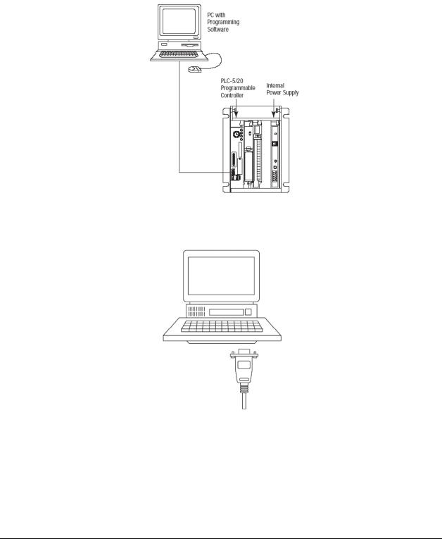
1.6Connect your PC to the Processor
1Connect the right-angle connector end of the cable to your controller at the communications port.
2Connect the straight connector end of the cable to the serial port on your computer.
Page 14 of 109 |
ProSoft Technology, Inc. |
|
June 23, 2009 |

Start Here |
MVI71-MNET ♦ PLC Platform |
User Manual |
Modbus TCP/IP Interface Module |
|
|
1.7Download the Sample Program to the Processor
To download the sample program from RSLogix 5 to the PLC processor:
Note: The key switch on the front of the PLC processor must be in the REM position.
1If you are not already online to the processor, open the Communications menu, and then choose Download. RSLogix will establish communication with the processor.
2Click the Download button to transfer the sample program to the processor.
3When prompted, choose Computer to PLC
4RSLogix will compile the program and transfer it to the processor. This process may take a few minutes.
ProSoft Technology, Inc. |
Page 15 of 109 |
June 23, 2009 |
|
MVI71-MNET ♦ PLC Platform |
Start Here |
Modbus TCP/IP Interface Module |
User Manual |
|
|
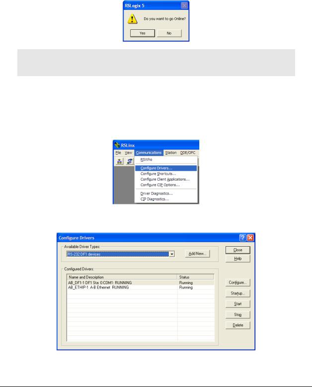
5When the download is complete, RSLogix will open another confirmation dialog box. Click OK to switch the processor from Program mode to Run mode.
Note: If you receive an error message during these steps, refer to your RSLogix documentation to interpret and correct the error.
1.7.1 Configuring the RSLinx Driver for the PC COM Port
If RSLogix is unable to establish communication with the processor, follow these steps
1Open RSLINX.
2Open the COMMUNICATIONS menu, and choose CONFIGURE DRIVERS.
This action opens the CONFIGURE DRIVERS dialog box.
Page 16 of 109 |
ProSoft Technology, Inc. |
|
June 23, 2009 |

Start Here |
MVI71-MNET ♦ PLC Platform |
User Manual |
Modbus TCP/IP Interface Module |
|
|
Note: If the list of configured drivers is blank, you must first choose and configure a driver from the Available Driver Types list. The recommended driver type to choose for serial communication with the processor is RS-232 DF1 DEVICES.
3Click to select the driver, and then click CONFIGURE. This action opens the
CONFIGURE ALLEN-BRADLEY DF1 COMMUNICATIONS DEVICE dialog box.
4Click the AUTO-CONFIGURE button. RSLinx will attempt to configure your serial port to work with the selected driver.
5When you see the message AUTO CONFIGURATION SUCCESSFUL, click the OK button to dismiss the dialog box.
Note: If the auto-configuration procedure fails, verify that the cables are connected correctly between the processor and the serial port on your computer, and then try again. If you are still unable to auto-configure the port, refer to your RSLinx documentation for further troubleshooting steps.
|
|
|
|
|
|
|
|
ProSoft Technology, Inc. |
Page 17 of 109 |
||
June 23, 2009 |
|
|
|
MVI71-MNET ♦ PLC Platform |
Start Here |
Modbus TCP/IP Interface Module |
User Manual |
|
|
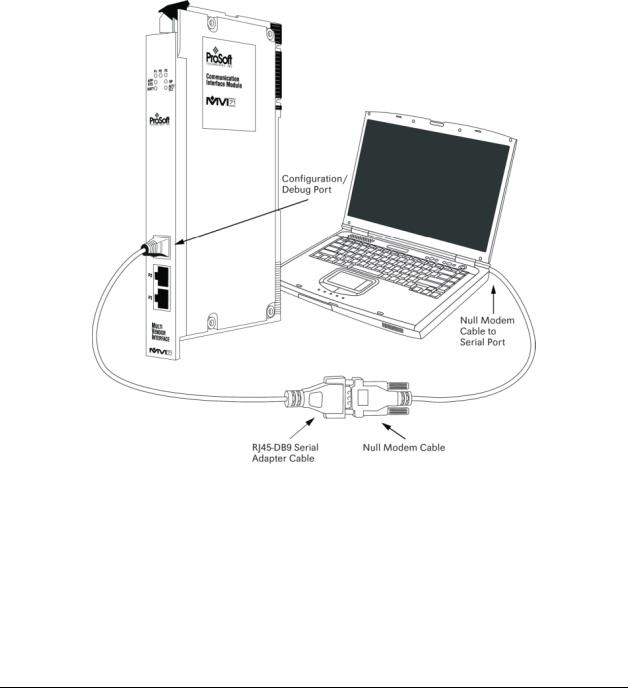
1.8Connect your PC to the Module
With the module securely mounted, connect your PC to the Configuration/Debug port using an RJ45-DB-9 Serial Adapter Cable and a Null Modem Cable.
1 Attach both cables as shown.
2 Insert the RJ45 cable connector into the Configuration/Debug port of the module.
3 Attach the other end to the serial port on your PC.
Page 18 of 109 |
ProSoft Technology, Inc. |
|
June 23, 2009 |

Module Configuration |
MVI71-MNET ♦ PLC Platform |
User Manual |
Modbus TCP/IP Interface Module |
|
|
2 |
Module Configuration |
|
|
|
In This Chapter |
|
|
|
Installing and Configuring the Module ................................................... |
19 |
|
|
|
Module Data .......................................................................................... |
22 |
|
|
Status Data............................................................................................ |
22 |
|
|
User Data .............................................................................................. |
22 |
|
|
Event Command Data ........................................................................... |
23 |
|
|
Modbus Message Data.......................................................................... |
23 |
|
|
ProSoft Configuration Builder ................................................................ |
23 |
|
Download the Project to the Module...................................................... |
40 |
|
This section contains the setup procedure, data, and ladder logic for successful application of the MVI71-MNET module. Each step in the setup procedure is defined in order to simplify the use of the module. Set up for the module for both the BTR/BTW and side-connect interfaces is covered.
2.1Installing and Configuring the Module
This chapter describes how to install and configure the module to work with your application. The configuration process consists of the following steps.
1Modify the module’s configuration files to meet the needs of your application, and copy the updated configuration to the module. Example configuration files are provided on the CD-ROM. Refer to the Modifying the Example Configuration File section, later in this chapter, for more information on the configuration files.
2Modify the example ladder logic to meet the needs of your application, and copy the ladder logic to the processor. Example ladder logic files are provided on the CD-ROM.
Note: If you are installing this module in an existing application, you can copy the necessary elements from the example ladder logic into your application.
The rest of this chapter describes these steps in more detail.
It is now time to edit the MNET.CFG file to set up the module for the specific application. Refer to the Configuration File section of this document. Download this configuration to the module along with the associated ladder logic.
ProSoft Technology, Inc. |
Page 19 of 109 |
June 23, 2009 |
|

MVI71-MNET ♦ PLC Platform |
Module Configuration |
Modbus TCP/IP Interface Module |
User Manual |
|
|
The next step in installing and configuring the module is to define whether the block transfer or side-connect interface will be utilized. If the block transfer interface is to be used you should be ready to connect the module to the Modbus TCP/IP network if the ladder logic is defined correctly.
If the side-connect interface is utilized, make sure the file SC_DATA.TXT on the Compact Flash Disk contains the correct first file number. You can run the setdnpsc.exe program to set the file number to be used with your application. Install the module in the rack and turn on the power. Connect the serial cable to the module’s debug/configuration port and exit the program by pressing [ESC][X]. This will cause the program to exit and remain at the operating system prompt. Run the setdnpsc.exe program with a command line argument of the file number to use for the first file. For example, to select N10: as the first file, enter the following:
SETDNPSC 10
The program will build the SC_DATA.TXT on the Compact Flash Disk (C: drive in the root directory).
Next, define the data files to be used with the application. If the block transfer interface is used, define the data files to hold the user data (read and write data). Enter the ladder logic to handle the blocks transferred between the module and the PLC. Download the program to the PLC and test the program with the module.
If the side-connect interface is used, no ladder logic is required for data transfer. The user data files to interface with the module must reside in contiguous order in the processor. The first file to be used by the interface is the status/control file. This is file number set in the SC_DATA.TXT file using the SETDNPSC.EXE program. The following table lists the files used by the side-connect interface:
File Number |
Example |
Size |
Description |
Cfg File |
N10 |
200 |
Control/Status File |
Cfg File+1 |
N11 |
to 1000 |
Data transferred from the module to the processor |
|
|
|
Other files for read data |
Cfg File+1+n |
N12 |
to 1000 |
Data transferred from the processor to the module |
|
|
|
|
Cfg File+1+n+m |
|
|
Other files for write data |
n is the number of read data files minus one. Each file contains up to 1000 words.
m is the number of write data files minus one. Each file contains up to 1000 words.
More than one read and/or write file may exist in an application. This is required when more than 1000 words of data are required. Two examples are given below for the files used with different data set sizes:
Page 20 of 109 |
ProSoft Technology, Inc. |
|
June 23, 2009 |
Module Configuration |
MVI71-MNET ♦ PLC Platform |
User Manual |
Modbus TCP/IP Interface Module |
|
|
2.1.1 Example of 240 words of read and write data (cfg file=10)
Data Files |
Description |
N11:0 to 239 |
Read data |
N12:0 to 239 |
Write data |
|
|
2.1.2Example of 2300 read and 3500 write data registers (cfg file=10)
Data Files |
Description |
N11:0 to 999 |
Read data words 0 to 999 |
|
|
N12:0 to 999 |
Read data words 1000 to 1999 |
|
|
N13:0 to 299 |
Read data words 2000 to 2299 |
N14:0 to 999 |
Write data words 0 to 999 |
N15:0 to 999 |
Write data words 1000 to 1999 |
|
|
N16:0 to 999 |
Write data words 2000 to 2999 |
|
|
N17:0 to 499 |
Write data words 3000 to 3499 |
Even if the files are not required for an application, they still are reserved and should only be used for that purpose. The read and write data contained in the last set of files possess the data transferred between the module and the processor. The read data file (Cfg File + 1) will contain data transferred from the module to the processor and should be associated with control data types. The write data file (Cfg File + 1 + n) will contain data passed to the module from the processor and should be associated with monitor data types.
Special care must be taken when defining the files for the side-connect interface. Because the module directly interacts with the PLC processor and its memory, any errors in the configuration may cause the processor to fault and it may even lose its configuration and program. After defining the files and populating them with the correct data, download the program to the processor, and place the processor in run mode. If everything is configured correctly, the module should start its normal operation.
The module is now set up and ready to be used with your application. Insert the module in the rack (with the power turned off) and attach the serial communication cables. Download the new application to the controller and place the processor in run mode. Download the new MNET.CFG file to the module using a terminal emulation program. If all the configuration parameters are set correctly and the module is attached to a network, the module’s Application LED (APP LED) should remain off and the backplane activity LED (BP ACT) should blink very rapidly.
ProSoft Technology, Inc. |
Page 21 of 109 |
June 23, 2009 |
|

MVI71-MNET ♦ PLC Platform |
Module Configuration |
Modbus TCP/IP Interface Module |
User Manual |
|
|
2.2Module Data
All data related to the MVI71-MNET module is stored in a user defined data files. It is the responsibility of the ladder logic programmer to construct all the data files required by the program and to write the ladder logic required to interface to these files.
2.3Status Data
When the side-connect interface is employed in the application, the status data is automatically transferred from the module to the first file used by the interface. The data is placed at an offset of 0 in the file and has the format shown in the Reference chapter.
When the block transfer interface is used, the status data is placed in the module’s internal database at the location specified by the Error/Status Offset parameter in the configuration file. If this data area is transferred to the processor in the read data area, it will be passed from the module to the processor in a normal BTR block. This will be placed in the normal read data area. The format of the data is exactly the same as shown above, but the user determines its position. Refer to the Reference chapter for a complete listing of the data stored in this object.
2.4User Data
When the side-connect interface is utilized, the read and write data is moved between the module and the processor without any ladder logic. The size of the data area and position of the data areas in the module’s database is determined by the parameters set in the configuration file.
When the block transfer interface is used, ladder logic is required to page the data between the module and the processor. The size of the data area and position of the data areas in the module’s database is determined by the parameters set in the configuration file.
The read data area should be set to match the value entered in the Read Register Count parameter of the MNET.CFG file. For ease of use, this array should be dimensioned as an even increment of 60 words. This data is paged up to 60 words at a time from the module to the processor. The Read Data task is responsible for placing the data received into the proper position in the read data array. Use this data for status and control in the ladder logic of the processor.
The write data area should be set to match the value entered in the Write Register Count parameter of the MNET.CFG file. For ease of use, this array should be dimensioned as even increments of 60 words. This data is paged up to 60 words at a time from the processor to the module. The Write Data task is responsible for placing the write data into the output image for transfer to the module. This data is passed from the processor to the module for status and control information for use in other nodes on the network.
Page 22 of 109 |
ProSoft Technology, Inc. |
|
June 23, 2009 |

Module Configuration |
MVI71-MNET ♦ PLC Platform |
User Manual |
Modbus TCP/IP Interface Module |
|
|
2.5Event Command Data
A user file containing Event Command Data is only required when event commands are utilized in the application. This file holds the information required for an event command. An array of these objects should be defined and hold the event command set to be employed in the application.
2.6Modbus Message Data
This new version of the module’s program includes the pass-through mode. In this mode, write messages sent to a slave port are passed directly through to the processor. It is the responsibility of the ladder logic to process the message received using this feature. If the side-connect interface is used, this data set will be placed in the file selected in the SC_DATA.TXT file starting at register offset 50. Ladder logic is required to parse the message or data set received and to place the data in the correct user data file.
If the block transfer interface is utilized, the pass-through messages will be passed from the module to the processor in special control blocks. Ladder logic is required to handle each block received and to place the data in the correct user data file.
This information is passed from the module to the processor using a block identification code of 9996 if the unformatted pass-through mode (code 1) is selected. Word two of this block contains the length of the message and the message starts at word 3. Other controller tags are required to store the controlled values contained in these messages. The Modbus protocol supports control of binary output (coils - functions 5 and 15) and registers (functions 6 and 16).
Additionally, formatted message blocks can be sent from the module to the processor when the pass-through option is selected using the format selection (codes 2 or 3 in the MNET.CFG file). These blocks require less decoding than the unformatted blocks. Refer to the user manual for a full discussion on utilizing the pass-through option in an application.
2.7ProSoft Configuration Builder
ProSoft Configuration Builder (PCB) provides a quick and easy way to manage module configuration files customized to meet your application needs. PCB is not only a powerful solution for new configuration files, but also allows you to import information from previously installed (known working) configurations to new projects.
ProSoft Technology, Inc. |
Page 23 of 109 |
June 23, 2009 |
|
MVI71-MNET ♦ PLC Platform |
Module Configuration |
Modbus TCP/IP Interface Module |
User Manual |
|
|
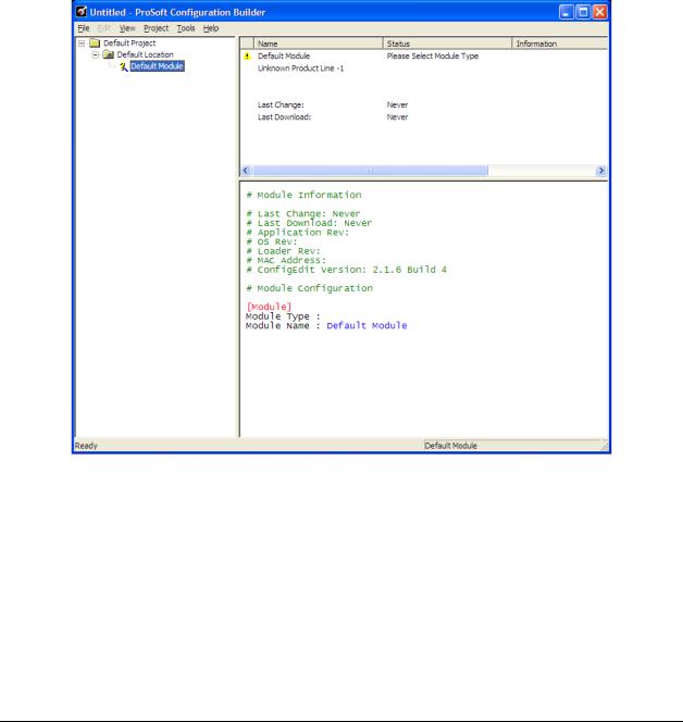
2.7.1 Set Up the Project
To begin, start ProSoft Configuration Builder. If you have used other Windows configuration tools before, you will find the screen layout familiar. ProSoft Configuration Builder’s window consists of a tree view on the left, an information pane and a configuration pane on the right side of the window. When you first start ProSoft Configuration Builder, the tree view consists of folders for Default Project and Default Location, with a Default Module in the Default Location folder. The following illustration shows the ProSoft Configuration Builder window with a new project.
Page 24 of 109 |
ProSoft Technology, Inc. |
|
June 23, 2009 |
Module Configuration |
MVI71-MNET ♦ PLC Platform |
User Manual |
Modbus TCP/IP Interface Module |
|
|
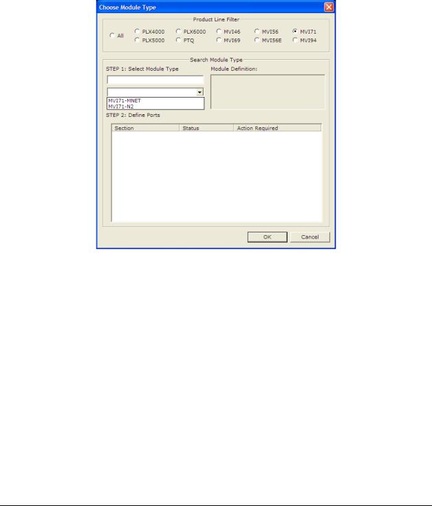
Your first task is to add the MVI71-MNET module to the project.
1Use the mouse to select "Default Module" in the tree view, and then click the right mouse button to open a shortcut menu.
2On the shortcut menu, choose "Choose Module Type". This action opens the Choose Module Type dialog box.
3In the Product Line Filter area of the dialog box, select MVI71. In the Select Module Type dropdown list, select MVI71-MNET, and then click OK to save your settings and return to the ProSoft Configuration Builder window.
The next task is to set the module parameters.
ProSoft Technology, Inc. |
Page 25 of 109 |
June 23, 2009 |
|

MVI71-MNET ♦ PLC Platform |
Module Configuration |
Modbus TCP/IP Interface Module |
User Manual |
|
|
2.7.2 Set Module Parameters
Notice that the contents of the information pane and the configuration pane changed when you added the MVI71-MNET module to the project.
At this time, you may wish to rename the "Default Project" and "Default Location" folders in the tree view.
To rename an object:
1Select the object, and then click the right mouse button to open a shortcut menu. From the shortcut menu, choose RENAME.
2Type the name to assign to the object.
3Click away from the object to save the new name.
Module Entries
To configure module parameters
1Click on the plus sign next to the  icon to expand module information.
2Double-click the  icon to open the EDIT dialog box.
3To edit a parameter, select the parameter in the left pane and make your changes in the right pane.
4Click OK to save your changes.
Page 26 of 109 |
ProSoft Technology, Inc. |
|
June 23, 2009 |

Module Configuration |
MVI71-MNET ♦ PLC Platform |
User Manual |
Modbus TCP/IP Interface Module |
|
|
Printing a Configuration File
To print a configuration file:
1Select the MODULE icon, and then click the right mouse button to open a shortcut menu.
2On the shortcut menu, choose VIEW CONFIGURATION. This action opens the
VIEW CONFIGURATION window.
3On the VIEW CONFIGURATION window, open the FILE menu, and choose PRINT. This action opens the PRINT dialog box.
4On the PRINT dialog box, choose the printer to use from the dropdown list, select printing options, and then click OK.
2.7.3 [Module]
This section of the configuration describes the database setup and module level parameters. This section provides the module with a unique name, identifies the method of failure for the communications for the module if the processor is not in run, and describes how to initialize the module upon startup.
Module Name
0 to 80 characters
This parameter assigns a name to the module that can be viewed using the configuration/debug port. Use this parameter to identify the module and the configuration file.
Error/Status Pointer
-1 to 4955
Starting register location in virtual Modbus database for the error/status table. If a value of -1 is entered, the error/status data will not be placed in the database. All other valid values determine the starting location of the data. This data area includes the module version information and all server error/status data.
Read Register Start
0 to 4999
This parameter specifies the starting register in the module where data will be transferred from the module to the processor. Valid range for this parameter is 0 to 4999.
Read Register Count
0 to 5000
This parameter specifies the number of registers to be transferred from the module to the processor. Valid entry for this parameter is 0 to 5000.
ProSoft Technology, Inc. |
Page 27 of 109 |
June 23, 2009 |
|

MVI71-MNET ♦ PLC Platform |
Module Configuration |
Modbus TCP/IP Interface Module |
User Manual |
|
|
Write Register Start
0 to 4999
This parameter specifies the starting register in the module where the data will be transferred from the processor to the module. Valid range for this parameter is 0 to 4999.
Write Register Count
0 to 5000
This parameter specifies the number of registers to transfer from the processor to the module. Valid entry for this parameter is 0 to 5000 words.
Failure Flag Count
0 through 65535
This parameter specifies the number of successive transfer errors that must occur before the communication ports are shut down. If the parameter is set to 0, the communication ports will continue to operate under all conditions. If the value is set larger than 0 (1 to 65535), communications will cease if the specified number of failures occur.
Initialize Output Data
Yes or No
The Initialize Output Data parameter determines if the output data for the module should be initialized with values from the processor. If the value is set to N, the output data will be initialized to 0. If the value is set to Y during initialization, the module will invert (for this scan only) all backplane commands (Type 2).
Pass-Through Mode
0, 1, 2 or 3
This parameter specifies the pass-through mode for write messages received by the MNET and MBAP server ports.
If the parameter is set to 0, all write messages will be placed in the module’s virtual database.
If a value of 1 is entered, write messages received will be sent to the processor as unformatted messages.
If a value of 2 is entered, write messages received will be sent to the processor as formatted messages.
If a value of 3 is entered, write messages received will be sent to the processor with the bytes swapped in a formatted message.
Page 28 of 109 |
ProSoft Technology, Inc. |
|
June 23, 2009 |

Module Configuration |
MVI71-MNET ♦ PLC Platform |
User Manual |
Modbus TCP/IP Interface Module |
|
|
Duplex/Speed Code
0, 1, 2, 3 or 4
This parameter allows you to force the module to use a specific duplex and speed setting.
Value = 1: Half duplex, 10 MB speed
Value = 2: Full duplex, 10 MB speed
Value = 3: Half duplex, 100 MB speed
Value = 4: Full duplex, 100 MB speed
Value = 0: Auto negotiate.
Auto Negotiate is the default value for backward compatibility. This feature is not implemented in older software revisions.
2.7.4 [Static ARP Table]
The Static ARP Table defines a list of static IP addresses that the module will use when an ARP (Address Resolution Protocol) is required. The module will accept up to 40 static IP/MAC address data sets.
Use the Static ARP table to reduce the amount of network traffic by specifying IP addresses and their associated MAC (hardware) addresses that the MVI71MNET module will be communicating with regularly.
Important: If the device in the field is changed, this table must be updated to contain the new MAC address for the device and downloaded to the module. If the MAC is not changed, no communications with the module will be provided.
IP Address
Dotted notation
This table contains a list of static IP addresses that the module will use when an
# ARP is required. The module will accept up to 40 static IP/MAC address data sets.
Important: If the device in the field is changed, this table must be updated to contain the new MAC address for the device and downloaded to the module. If the MAC is not changed, no communications with the module will occur.
Hardware MAC Address
Hex Value
This table contains a list of static MAC addresses that the module will use when an # ARP is required. The module will accept up to 40 static IP/MAC address data sets.
Important: If the device in the field is changed, this table must be updated to contain the new MAC address for the device and downloaded to the module. If the MAC is not changed, no communications with the module will occur.
|
|
|
|
|
|
|
|
ProSoft Technology, Inc. |
Page 29 of 109 |
||
June 23, 2009 |
|
|
|

MVI71-MNET ♦ PLC Platform |
Module Configuration |
Modbus TCP/IP Interface Module |
User Manual |
|
|
2.7.5 [MNET Client x]
This section defines the configuration for the master device(s) simulated on MNET port.
Error/Status Pointer
-1 to 4990
Starting register location in virtual database for the error/status table for this client. If a value of -1 is entered, the error/status data will not be placed in the database. All other valid values determine the starting location of the data.
Minimum Command Delay
0 to 65535
This parameter specifies the number of milliseconds to wait between the initial issuance of a command. This parameter can be used to delay all commands sent to slaves to avoid "flooding" commands on the network. This parameter does not affect retries of a command as they will be issued when failure is recognized.
Command Error Pointer
-1 to 4999
This parameter sets the address in the internal database where the command error data will be placed. If the value is set to -1, the data will not be transferred to the database.
Response Timeout
0 to 65535 milliseconds
This parameter represents the message response timeout period in 1 millisecond increments. This is the time that a client will wait before re-transmitting a command if no response is received from the addressed server. The value is set depending upon the communication network used and the expected response time of the slowest device on the network.
Retry Count
0 to 10
This parameter specifies the number of times a command will be retried if it fails.
Float Flag
Yes or No
This flag specifies if the floating-point data access functionality is to be implemented. If the float flag is set to Yes, Modbus functions 3, 6 and 16 will interpret floating point values for registers as specified by the two following parameters.
Page 30 of 109 |
ProSoft Technology, Inc. |
|
June 23, 2009 |
Loading...