


DFCM
ProLinx Gateway
DF1 Master/Slave
October 15, 2010
DRIVER MANUAL
Your Feedback Please
We always want you to feel that you made the right decision to use our products. If you have suggestions, comments, compliments or complaints about our products, documentation, or support, please write or call us.
How to Contact Us
ProSoft Technology
5201 Truxtun Ave., 3rd Floor Bakersfield, CA 93309
+1 (661) 716-5100
+1 (661) 716-5101 (Fax) www.prosoft-technology.com support@prosoft-technology.com
Copyright © 2010 ProSoft Technology, Inc., all rights reserved.
DFCM Driver Manual
October 15, 2010
ProSoft Technology ®, ProLinx ®, inRAx ®, ProTalk ®, and RadioLinx ® are Registered Trademarks of ProSoft Technology, Inc. All other brand or product names are or may be trademarks of, and are used to identify products and services of, their respective owners.
ProSoft Technology® Product Documentation
In an effort to conserve paper, ProSoft Technology no longer includes printed manuals with our product shipments. User Manuals, Datasheets, Sample Ladder Files, and Configuration Files are provided on the enclosed CD-ROM, and are available at no charge from our web site: www.prosoft-technology.com
Printed documentation is available for purchase. Contact ProSoft Technology for pricing and availability. North America: +1.661.716.5100
Asia Pacific: +603.7724.2080
Europe, Middle East, Africa: +33 (0) 5.3436.87.20 Latin America: +1.281.298.9109
Important Installation Instructions
Power, Input, and Output (I/O) wiring must be in accordance with Class I, Division 2 wiring methods, Article 501-4 (b) of the National Electrical Code, NFPA 70 for installation in the U.S., or as specified in Section 18-1J2 of the Canadian Electrical Code for installations in Canada, and in accordance with the authority having jurisdiction. The following warnings must be heeded:
AWARNING - EXPLOSION HAZARD - SUBSTITUTION OF COMPONENTS MAY IMPAIR SUITABILITY FOR CLASS I, DIV. 2;
BWARNING - EXPLOSION HAZARD - WHEN IN HAZARDOUS LOCATIONS, TURN OFF POWER BEFORE REPLACING OR WIRING MODULES
CWARNING - EXPLOSION HAZARD - DO NOT DISCONNECT EQUIPMENT UNLESS POWER HAS BEEN
SWITCHED OFF OR THE AREA IS KNOWN TO BE NON-HAZARDOUS.
DTHIS DEVICE SHALL BE POWERED BY CLASS 2 OUTPUTS ONLY.
ProLinx® Products Warnings
WARNING – EXPLOSION HAZARD – DO NOT DISCONNECT EQUIPMENT UNLESS POWER HAS BEEN SWITCHED OFF OR THE AREA IS KNOWN TO BE NON-HAZARDOUS.
AVERTISSEMENT – RISQUE D'EXPLOSION – AVANT DE DÉCONNECTER L'EQUIPMENT, COUPER LE COURANT OU S'ASSURER QUE L'EMPLACEMENT EST DÉSIGNÉ NON DANGEREUX.
ProLinx Gateways with Ethernet Ports
Series C ProLinx™ Gateways with Ethernet ports do NOT include the HTML Web Server. The HTML Web Server must be ordered as an option. This option requires a factory-installed hardware addition. The HTML Web Server now supports:
8 MB file storage for HTML files and associated graphics files (previously limited to 384K)
32K maximum HTML page size (previously limited to 16K)
To upgrade a previously purchased Series C model:
Contact your ProSoft Technology distributor to order the upgrade and obtain a Returned Merchandise Authorization (RMA) to return the unit to ProSoft Technology.
To order a ProLinx Plus gateway with the -WEB option
Add -WEB to the standard ProLinx part number. For example, 5201-MNET-MCM-WEB.
Markings
Electrical Specifications
Label Markings
CL I Div 2 GPs A, B, C, D II 3 G
Ex nA nL IIC X 0°C <= Ta <= 60°C
II – Equipment intended for above ground use (not for use in mines). 3 – Category 3 equipment, investigated for normal operation only.
G – Equipment protected against explosive gasses.

Agency Approvals and Certifications
cULus |
ISA 12.12.01 Class I, Div 2 Groups A, B, C, D |
|
|
cULus |
C22.2 No. 213-M1987 |
|
|
|
183151 |
DFCM ♦ ProLinx Gateway |
Contents |
DF1 Master/Slave |
Driver Manual |
|
|
Contents
Your Feedback Please........................................................................................................................ |
2 |
How to Contact Us .............................................................................................................................. |
2 |
ProSoft Technology® Product Documentation .................................................................................... |
2 |
Important Installation Instructions ....................................................................................................... |
3 |
ProLinx® Products Warnings............................................................................................................... |
3 |
ProLinx Gateways with Ethernet Ports ............................................................................................... |
3 |
To upgrade a previously purchased Series C model:.................................................................... |
3 |
To order a ProLinx Plus gateway with the -WEB option................................................................ |
3 |
Markings.............................................................................................................................................. |
3 |
1 |
Functional Overview |
9 |
||
|
|
|
|
|
1.1 |
|
Master/Slave Serial Port(s) ..................................................................................... |
10 |
|
1.2 |
|
Module Internal Database ....................................................................................... |
11 |
|
|
1.2.1 |
DF1 Serial Port Driver Access to Database ............................................................ |
11 |
|
|
2 |
Protocol Functional Specifications |
13 |
||
|
|
|
|
|
|
|
|
2.1 |
Functional Specifications - DF1 Master/Slave ........................................................ |
13 |
|
|
|
2.2 |
Serial Port Specifications ........................................................................................ |
15 |
|
3 |
DFCM Slave Driver Operation |
17 |
|||
|
|
|
|
|
|
|
|
3.1 |
File Simulation ......................................................................................................... |
18 |
|
|
|
3.2 |
Example Slave Port Application .............................................................................. |
19 |
|
|
|
3.3 |
Slave Port Command Support ................................................................................ |
20 |
|
|
4 |
Communication Port Cables |
21 |
||
|
|
|
|
|
|
|
|
4.1 |
Serial Port Cable Connections: Multiple Port Units................................................. |
22 |
|
|
|
4.1.1 |
Port 0, 1, 2, 3: RS-232 - Null Modem (DTE with Hardware Handshaking) ............. |
22 |
|
|
|
4.1.2 |
Port 0, 1, 2, 3: RS-232 - Null Modem (DTE without Hardware Handshaking) ........ |
23 |
|
|
|
4.1.3 |
Port 0, 1, 2, 3: RS-232 - DTE to DCE Modem Connection ..................................... |
23 |
|
|
|
4.1.4 |
Port 0, 1, 2, 3: RS-422 Interface Connections ........................................................ |
24 |
|
|
|
4.1.5 |
Port 0, 1, 2, 3: RS-485 Interface Connections ........................................................ |
24 |
|
|
5 |
LED Indicators |
25 |
||
|
|
|
|
|
|
|
|
5.1 |
Base Module LEDs.................................................................................................. |
26 |
|
|
|
5.2 |
LEDs for Serial DF1 Protocol Ports......................................................................... |
27 |
|
|
|
5.3 |
DFNT Pass-Through (Debug) Port LEDs................................................................ |
28 |
|
6 |
DFCM Protocol Configuration |
29 |
|||
|
|
|
|
|
|
|
|
6.1 |
[DF1 Pass-Through Port] ........................................................................................ |
30 |
|
|
|
6.1.1 |
Configuration Values ............................................................................................... |
31 |
|
|
|
6.1.2 |
Switching between Pass-Through and Debug/Configuration ................................. |
32 |
|
|
|
6.2 |
[DF1 Port x] ............................................................................................................. |
33 |
|
|
|
|
|
||
ProSoft Technology, Inc. |
Page 5 of 88 |
||||
October 15, 2010 |
|
|
|
||
Contents |
|
DFCM ♦ ProLinx Gateway |
Driver Manual |
|
DF1 Master/Slave |
|
|
|
6.2.1 |
Enabled................................................................................................................... |
33 |
6.2.2 |
Type ........................................................................................................................ |
33 |
6.2.3 |
Local Station ID....................................................................................................... |
33 |
6.2.4 |
Protocol................................................................................................................... |
33 |
6.2.5 |
Termination Type .................................................................................................... |
33 |
6.2.6 |
Baud Rate ............................................................................................................... |
33 |
6.2.7 |
Parity....................................................................................................................... |
33 |
6.2.8 |
Data Bits ................................................................................................................. |
34 |
6.2.9 |
Stop Bits.................................................................................................................. |
34 |
6.2.10 |
Minimum Response Delay...................................................................................... |
34 |
6.2.11 |
RTS On ................................................................................................................... |
34 |
6.2.12 |
RTS Off ................................................................................................................... |
34 |
6.2.13 |
Use CTS Line.......................................................................................................... |
34 |
6.2.14 |
Response Timeout.................................................................................................. |
35 |
6.2.15 |
Retry Count............................................................................................................. |
35 |
6.3 |
DF1 Master Configuration....................................................................................... |
36 |
6.3.1 |
ENQ Delay .............................................................................................................. |
36 |
6.3.2 |
Minimum Command Delay ..................................................................................... |
36 |
6.3.3 |
Error Delay Count ................................................................................................... |
36 |
6.3.4 |
Command Error Pointer .......................................................................................... |
36 |
6.3.5 |
Slave List Pointer .................................................................................................... |
36 |
6.4 |
DF1 Slave Configuration......................................................................................... |
37 |
6.4.1 |
First File .................................................................................................................. |
37 |
6.4.2 |
File Size .................................................................................................................. |
37 |
6.4.3 |
File Offset................................................................................................................ |
37 |
6.5 |
[DF1 PORT x COMMANDS]................................................................................... |
38 |
6.5.1 |
Command List Overview......................................................................................... |
38 |
|
7 |
Commands Supported by the Module |
|
39 |
||
|
|
|
|
|
|
|
|
|
7.1.1 |
Command Entry Formats........................................................................................ |
|
42 |
|
8 |
Reference |
|
|
45 |
||
|
|
|
|
|
|
|
8.1 |
|
Serial Port Protocol Error/Status Data .................................................................... |
|
46 |
||
|
|
8.1.1 |
Viewing Error and Status Data ............................................................................... |
|
46 |
|
|
|
8.1.2 |
DF1 Error and Status Data Area Addresses .......................................................... |
|
46 |
|
|
|
8.1.3 |
DF1 Ports - Error/Status Data................................................................................. |
|
47 |
|
|
|
8.1.4 |
Master Port: Command Errors................................................................................ |
|
47 |
|
|
|
8.1.5 |
Master Port: DF1 Slave List Status......................................................................... |
|
48 |
|
8.2 |
|
Error Codes............................................................................................................. |
|
50 |
||
|
|
8.2.1 |
Local STS Error Codes ........................................................................................... |
|
50 |
|
|
|
8.2.2 |
Remote STS Error Codes....................................................................................... |
|
50 |
|
|
|
8.2.3 |
Errors When EXT STS Is Present .......................................................................... |
|
51 |
|
|
|
8.2.4 |
Module Specific Error (not DFCM Compliant) ........................................................ |
|
52 |
|
8.3 |
|
DF1 Configuration Error Word ................................................................................ |
|
53 |
||
8.4 |
|
DF1 Command Set For ProSoft Technology Communication Modules ................. |
54 |
|||
|
|
8.4.1 |
Introduction ............................................................................................................. |
|
54 |
|
|
|
8.4.2 |
Command Function Codes ..................................................................................... |
|
55 |
|
|
|
8.4.3 |
PLC-5 Processor Specifics ..................................................................................... |
|
66 |
|
|
|
8.4.4 |
SLC Processor Specifics ........................................................................................ |
|
67 |
|
|
|
8.4.5 |
MicroLogix Processor Specifics.............................................................................. |
|
67 |
|
|
|
8.4.6 |
ControlLogix Processor Specifics ........................................................................... |
|
68 |
|
|
|
|
|
|
|
|
Page 6 of 88 |
|
|
ProSoft Technology, Inc. |
|||
|
|
|
|
October 15, 2010 |
||
DFCM ♦ ProLinx Gateway |
|
Contents |
DF1 Master/Slave |
|
Driver Manual |
|
|
|
8.5 |
DF1 Command List Form ........................................................................................ |
69 |
8.6 |
Moving Data ............................................................................................................ |
70 |
8.7 |
5102-DFS3-DFM Configuration Information ........................................................... |
71 |
8.7.1 |
Parameter Descriptions........................................................................................... |
73 |
9 |
Support, Service & Warranty |
|
77 |
||
|
|
|
|
|
|
|
Contacting Technical Support........................................................................................................... |
|
77 |
||
|
9.1 |
Return Material Authorization (RMA) Policies and Conditions................................ |
79 |
||
|
9.1.1 |
Returning Any Product ............................................................................................ |
|
79 |
|
|
9.1.2 |
Returning Units Under Warranty ............................................................................. |
|
80 |
|
|
9.1.3 |
Returning Units Out of Warranty ............................................................................. |
|
80 |
|
|
9.2 |
LIMITED WARRANTY............................................................................................. |
|
81 |
|
|
9.2.1 |
What Is Covered By This Warranty......................................................................... |
|
81 |
|
|
9.2.2 |
What Is Not Covered By This Warranty .................................................................. |
|
82 |
|
|
9.2.3 |
Disclaimer Regarding High Risk Activities .............................................................. |
|
82 |
|
|
9.2.4 |
Intellectual Property Indemnity................................................................................ |
|
83 |
|
|
9.2.5 |
Disclaimer of all Other Warranties .......................................................................... |
|
83 |
|
|
9.2.6 |
Limitation of Remedies ** ........................................................................................ |
|
84 |
|
|
9.2.7 |
Time Limit for Bringing Suit ..................................................................................... |
|
84 |
|
|
9.2.8 |
No Other Warranties ............................................................................................... |
|
84 |
|
|
9.2.9 |
Allocation of Risks ................................................................................................... |
|
84 |
|
|
9.2.10 |
Controlling Law and Severability............................................................................. |
|
85 |
|
10 |
Index |
|
Error! Bookmark not defined. |
||
|
|
|
|
|
|
ProSoft Technology, Inc. |
Page 7 of 88 |
October 15, 2010 |
|
Contents |
DFCM ♦ ProLinx Gateway |
Driver Manual |
DF1 Master/Slave |
|
|
Page 8 of 88 |
ProSoft Technology, Inc. |
|
October 15, 2010 |
DFCM ♦ ProLinx Gateway |
Functional Overview |
DF1 Master/Slave |
Driver Manual |
|
|
1Functional Overview
In This Chapter |
|
|
|
Master/Slave Serial Port(s).................................................................... |
10 |
|
Module Internal Database ..................................................................... |
11 |
The DF1 Master/Slave Protocol driver can exist in a single port (DFCM) or a multiple port (DFCM4) implementation. In either case, the driver can be configured on an individual port basis to operate as either a DF1 Master or a Slave. Each port is independently configured for communication on a DF1 network and interfaces with the internal database in the module.
ProSoft Technology, Inc. |
Page 9 of 88 |
October 15, 2010 |
|

Functional Overview |
DFCM ♦ ProLinx Gateway |
Driver Manual |
DF1 Master/Slave |
|
|
1.1Master/Slave Serial Port(s)
The ProLinx module supports the DF1 protocol as a Master or Slave on up to four ports. Each of the ports is individually configurable.
The relationship between the port labeling on the front of the ProLinx module and the application is as follows:
Port Label |
Function |
|
|
Debug |
Debug/Configuration |
|
|
Port 0 |
DF1 Port 0 |
|
|
Following ports only exist on multiple port units |
|
|
|
Port 1 |
DF1 Port 1 |
|
|
Port 2 |
DF1 Port 2 |
|
|
Port 3 |
DF1 Port 3 |
|
|
One or more DF1 protocol master ports can be configured on the module to continuously interface with DF1 slave devices over a serial communication interface (RS-232, RS-422 or RS-485). Each port is configured independently. Support for half-duplex (master-slave) and full-duplex (point-to-point) DF1 links are provided on the ports. User defined commands determine the commands to be issued on each port. Up to 100 commands can be defined for each port. Data read from the devices are placed in the virtual database. Any write requests for the DF1 slave devices are sourced with data from the virtual database.
The module can be configured to place slave devices that are not responding to commands from the master ports at a lower priority. If the module recognizes that a slave device has failed to respond to a message after the user defined retry count, it will mark the slave as "in communication failure" and set the error delay counter to the specified value. Each time the module encounters this slave in the command list, the counter will be decremented. When the value reaches zero, the slave will be placed in an active status. This facility can improve communication throughput on the network.
If the DF1 master port is configured to support the DF1 half-duplex protocol, the master port can be used to route messages between slaves. Peer-to-peer communication is accomplished by the master constantly polling all the slaves on the network and relaying the messages received. The slaves must contain ladder logic with MSG commands to generate and accept messages. This routing can be used in conjunction with the normal command processing discussed above.
DF1 slave devices can be emulated on the module to interface with remote DF1 master devices. Each port is configured independently. Support for half-duplex (master-slave) and full-duplex (point-to-point) DF1 links are provided on the ports. Simulation of a selected set of functions from the basic, PLC5 and SLC command sets are supported. Virtual files are mapped to the internal database in the module to provide support of the PLC5 and SLC command sets.
Page 10 of 88 |
ProSoft Technology, Inc. |
|
October 15, 2010 |
DFCM ♦ ProLinx Gateway |
Functional Overview |
DF1 Master/Slave |
Driver Manual |
|
|
1.2Module Internal Database
The internal database is central to the functionality of the module. This database is shared between all the ports on the module and is used as a conduit to pass information from one device on one network to one or more devices on another network. This permits data from devices on one communication port to be viewed and controlled by devices on another port. In addition to data from the slave and master ports, status and error information generated by the module can also be mapped into the internal database.
1.2.1 DF1 Serial Port Driver Access to Database
The following diagram describes the flow of data between the serial port drivers and the internal database.
The Master driver uses the database in two ways:
1A read command issued to a slave device by the master driver will return the slave data into the internal database
2A write command issued to a slave device by the master driver uses the data in the internal database to write to the slave device
The slave driver accesses data from the internal database. External DF1 master devices can monitor and control data in this database through these slave port(s). Setup of the slave ports only requires the CFG file.
ProSoft Technology, Inc. |
Page 11 of 88 |
October 15, 2010 |
|
Functional Overview |
DFCM ♦ ProLinx Gateway |
Driver Manual |
DF1 Master/Slave |
|
|
Page 12 of 88 |
ProSoft Technology, Inc. |
|
October 15, 2010 |
DFCM ♦ ProLinx Gateway |
Protocol Functional Specifications |
DF1 Master/Slave |
Driver Manual |
|
|
2Protocol Functional Specifications
2.1Functional Specifications - DF1 Master/Slave
The DF1 Master/Slave Protocol driver provides extensive support for both Master and Slave implementations of the protocol. The serial port on the module is userconfigurable to support the DF1 protocol (Master or Slave, Error Checking,
Baud rate, and so on).
DF1 General Specifications
Internal Database |
10000 registers (words) available |
|
|
Communication parameters |
Local Station ID: 0 to 254 |
|
Ports 1 to 3 Baud Rate: 110 to 115K baud |
|
Stop Bits: 1 |
|
Data Bits: 8 |
|
Parity: None, Even, Odd |
|
RTS Timing delays: 0 to 65535 milliseconds |
Error Checking |
BCC and CRC |
Miscellaneous |
Full hardware handshaking control, providing |
|
radio, smart modem and multi-drop support |
|
Floating point data supported |
|
|
DF1 Master
The ports on the module can be individually configured as Master ports. When configured in master mode, the DFCM module is capable of reading and writing data to remote DF1 devices.
DF1 Modes |
Full-Duplex - Master (Module generates |
|
commands) |
|
Half-Duplex - Polling |
|
|
Command List |
Up to 100 commands per Master port, each fully- |
|
configurable for function, slave address, register |
|
to/from addressing and word/bit count |
Polling of Command List |
User-configurable polling of commands, including |
|
disabled, continuous, and on change of data (write |
|
only) |
Configurable Parameters per |
Min Command Delay |
Master port |
Number of Commands |
|
Response Timeout |
|
Retry Count |
|
Slave List Error Pointer |
|
|
ProSoft Technology, Inc. |
Page 13 of 88 |
October 15, 2010 |
|

Protocol Functional Specifications |
DFCM ♦ ProLinx Gateway |
Driver Manual |
DF1 Master/Slave |
|
|
DF1 Slave
The ports on the module can be individually configured to support the Slave mode of the DF1 protocol. When in slave mode, the module can accept DF1 commands from a master to read/write data stored in the module’s internal registers.
DF1 Modes |
Full Duplex - Slave (not peer mode) |
|
Half Duplex - Polled |
|
|
Configurable parameters per |
Data Table File Start (File N[x] 0 to 999) |
slave port |
Data Table File Size (1 to 1000 words) |
|
Data Table location in database (0 to 3999) |
|
|
Page 14 of 88 |
ProSoft Technology, Inc. |
|
October 15, 2010 |

DFCM ♦ ProLinx Gateway |
Protocol Functional Specifications |
DF1 Master/Slave |
Driver Manual |
|
|
2.2 |
Serial Port Specifications |
|
|
|
|
|
Type |
Specifications |
|
|
|
|
Serial Ports |
|
|
|
|
|
Serial Port Cables (DB-9M Connector) |
One DIN to DB-9M cable included per configurable |
|
|
serial port |
|
|
|
|
Port 0 |
RS-232/422/485: jumper selectable |
|
|
DB-9M connector |
|
|
Hardware Handshaking: RTS,CTS,DTR,DSR,DCD |
|
|
|
|
Port 1, 2, 3 |
RS-232/422/485: Software configurable |
|
Protocol Ports 1, 2, 3 |
DB-9M connector |
|
(Only if product includes extra serial ports) |
Hardware Handshaking: RTS,CTS,DTR,DSR,DCD |
|
|
|
|
Serial Port Isolation |
2500V RMS port-to-port isolation per UL 1577. |
|
|
3000V DC min. port to ground and port to logic |
|
|
power isolation. |
|
|
|
|
Serial Port Protection |
RS-485/422 port interface lines TVS diode protected |
|
|
at +/- 27V standoff voltage. |
RS-232 port interface lines fault protected to +/- 36V power on, +/- 40V power off.
ProSoft Technology, Inc. |
Page 15 of 88 |
October 15, 2010 |
|
Protocol Functional Specifications |
DFCM ♦ ProLinx Gateway |
Driver Manual |
DF1 Master/Slave |
|
|
Page 16 of 88 |
ProSoft Technology, Inc. |
|
October 15, 2010 |
DFCM ♦ ProLinx Gateway |
DFCM Slave Driver Operation |
DF1 Master/Slave |
Driver Manual |
|
|
3DFCM Slave Driver Operation
In This Chapter |
|
|
|
File Simulation....................................................................................... |
18 |
Example Slave Port Application ............................................................ |
19 |
|
|
Slave Port Command Support............................................................... |
20 |
This section discusses several characteristics in the module’s configuration and operation that are unique to the emulated DF1 slave ports. In order to support several types of DF1 devices, the slave ports require additional configuration parameters. If the basic command set is used, these features need not be considered. These features must be considered if the module has the potential of receiving a PLC5 or SLC command function.
ProSoft Technology, Inc. |
Page 17 of 88 |
October 15, 2010 |
|

DFCM Slave Driver Operation |
DFCM ♦ ProLinx Gateway |
Driver Manual |
DF1 Master/Slave |
|
|
3.1File Simulation
The PLC5 and SLC command sets require the use of data files. These entities are simulated in the module and are configured by the user. Data in these processors are stored in files such as N10:, F20: and A25:. Each file has a defined element size and length. The module simulates these files by assigning each element to a word-size (two bytes) register in the module’s database, and each file is set to a fixed, user-defined length. These files are mapped to the database under user control. A discussion of each parameter related to the file simulation is given below along with an example.
[SECTION]/Item |
Range |
Description |
|
|
|
[DF1 PORT 0] |
|
Configuration Header for Port 0 |
[DF1 PORT 1] |
|
Configuration Header for Port 1 |
[DF1 PORT 2] |
|
Configuration Header for Port 2 |
[DF1 PORT 3] |
|
Configuration Header for Port 3 |
|
|
|
First File: |
|
This parameter defines the first file number recognized by |
|
|
the module. If the value is set to 7, all requests for files |
|
|
less than 7 will be returned as an error message. Files |
|
|
greater than or equal to 7 will be processed as long as |
|
|
the elements referenced are valid for the database. If a |
|
|
request is received for an element beyond the last |
|
|
register in the database, the module will return an error |
|
|
message. |
File Size:
File Offset:
This parameter defines a constant size for all files simulated by the module. If the parameter is set to 100, all files will contain 100 elements. If the First File parameter is set to 7 and the File Size parameter is set to 100, all files (N7:, N8:, N9...) will contain 100 elements.
This parameter defines the starting address in the module’s internal database to be associated with the first element in the first file to be simulated. For example, if the First File parameter is set to 7 and the File Offset parameter is set to 1000, file element N7:0 will correspond to database register 1000 and N7:100 will correspond to register 1100.
Page 18 of 88 |
ProSoft Technology, Inc. |
|
October 15, 2010 |

DFCM ♦ ProLinx Gateway |
DFCM Slave Driver Operation |
DF1 Master/Slave |
Driver Manual |
|
|
3.2Example Slave Port Application
The example given below assumes that both ports 0 and 1 are configured as slave ports using the following table of parameters:
Parameter |
Port 0 |
Port1 |
|
|
|
First File |
7 |
10 |
|
|
|
File Size |
200 |
1000 |
|
|
|
File Offset |
1000 |
2000 |
|
|
|
The following illustration shows the file simulation feature in the module using the configuration defined above:
Port 0 |
|
Database Register |
|
Port 1 |
|
|
|
|
|
|
|
0 |
|
|
|
|
|
|
|
|
|
200 |
|
|
|
|
|
|
|
|
|
400 |
|
|
|
|
|
|
|
|
|
600 |
|
|
|
|
|
|
|
|
|
800 |
|
|
|
|
|
|
|
N7:0 |
→ |
1000 |
|
|
|
|
|
|
|
N8:0 |
→ |
1200 |
|
|
|
|
|
|
|
N9:0 |
→ |
1400 |
|
|
|
|
|
|
|
N10:0 |
→ |
1600 |
|
|
|
|
|
|
|
N11:0 |
→ |
1800 |
|
|
|
|
|
|
|
N12:0 |
→ |
2000 |
← |
N10:0 |
|
|
|
|
|
N13:0 |
→ |
2200 |
← |
N10:200 |
|
|
|
|
|
N14.0 |
→ |
2400 |
← |
N10:400 |
|
|
|
|
|
N15.0 |
→ |
2600 |
← |
N10:600 |
|
|
|
|
|
N16:0 |
→ |
2800 |
← |
N10:800 |
|
|
|
|
|
N17:0 |
→ |
3000 |
← |
N11:0 |
|
|
|
|
|
N18:0 |
→ |
3200 |
← |
N11:200 |
|
|
|
|
|
N19:0 |
→ |
3400 |
← |
N11:400 |
|
|
|
|
|
N20:0 |
→ |
3600 |
← |
N11:600 |
|
|
|
|
|
N21:0 |
→ |
3800 |
← |
N11:800 |
|
|
|
|
|
ProSoft Technology, Inc. |
Page 19 of 88 |
October 15, 2010 |
|
DFCM Slave Driver Operation |
DFCM ♦ ProLinx Gateway |
Driver Manual |
DF1 Master/Slave |
|
|
3.3Slave Port Command Support
The current version of the module will respond to the following list of DF1 commands. Future releases may support more functions as required by user applications.
Page 20 of 88 |
ProSoft Technology, Inc. |
|
October 15, 2010 |
DFCM ♦ ProLinx Gateway |
Communication Port Cables |
DF1 Master/Slave |
Driver Manual |
|
|
4Communication Port Cables
This section contains information on the cable and pin assignments for the ProLinx module's serial ports (RS-232/422/485). The ProLinx module will come with one to five serial ports, depending on the configuration purchased. In all cases, the protocol serial ports will have the same pinouts.
Example: The 5202-MNET-MCM4 module contains five serial communication ports; four
configurable protocol application ports and one Configuration/ Debug port.
The 5201-MNET-MCM module contains two serial communication ports; one configurable protocol
application port and one Configuration/Debug port.
Each physical serial port has an eight-pin Mini-DIN jack connector. A six-inch Mini-DIN-8Male to DB-9Male adapter cable is provided for each serial port. The DB-9M provides connections for RS-232, wired as Data Terminal Equipment (DTE), RS-422 and RS-485. The diagrams in the following topics detail the pin assignments for several possible electrical interface connections.
ProSoft Technology, Inc. |
Page 21 of 88 |
October 15, 2010 |
|
Communication Port Cables |
DFCM ♦ ProLinx Gateway |
Driver Manual |
DF1 Master/Slave |
|
|
4.1Serial Port Cable Connections: Multiple Port Units
The relationship between the port labeling on the front of the ProLinx module and the application is as follows:
The following ports only exist on units with more than one application serial port
Port 1 |
Application Port 1 (RS-232, RS-422, or RS-485 Modes Available) |
|
|
Port 2 |
Application Port 2 (RS-232, RS-422, or RS-485 Modes Available) |
|
|
Port 3 |
Application Port 3 (RS-232, RS-422, or RS-485 Modes Available) |
|
|
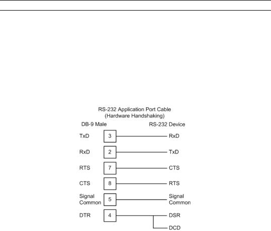
4.1.1Port 0, 1, 2, 3: RS-232 - Null Modem (DTE with Hardware Handshaking)
This type of connection is used when the device connected to the module requires hardware handshaking (control and monitoring of modem signal lines; Use CTS (page 34) parameter set to YES).
Page 22 of 88 |
ProSoft Technology, Inc. |
|
October 15, 2010 |
DFCM ♦ ProLinx Gateway |
Communication Port Cables |
DF1 Master/Slave |
Driver Manual |
|
|
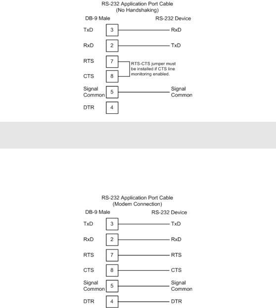
4.1.2Port 0, 1, 2, 3: RS-232 - Null Modem (DTE without Hardware Handshaking)
This type of connection can be used to connect the module to a computer or field device communication port.
Note: If the port is configured with the Use CTS (page 34) set to YES, then a jumper is required
between the RTS and the CTS line on the module connection.
4.1.3 Port 0, 1, 2, 3: RS-232 - DTE to DCE Modem Connection
This type of connection is required between the module and a modem or other communication device.
The Use CTS Line (page 34) parameter for the port configuration should be set to YES for most modem applications.
ProSoft Technology, Inc. |
Page 23 of 88 |
October 15, 2010 |
|
Communication Port Cables |
DFCM ♦ ProLinx Gateway |
Driver Manual |
DF1 Master/Slave |
|
|
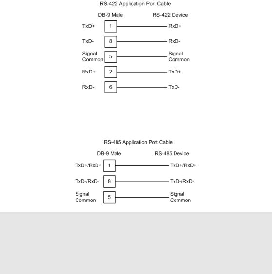
4.1.4 Port 0, 1, 2, 3: RS-422 Interface Connections
The following illustration applies when the RS-422 interface is selected.
4.1.5 Port 0, 1, 2, 3: RS-485 Interface Connections
The following illustration applies when the RS-485 interface is selected.
NOTE: This type of connection is commonly called a RS-485 half-duplex, 2-wire connection. If you have RS-485 4-wire, full-duplex devices, they can be connected to the module's serial ports by wiring together the TxD+ and RxD+ from the two pins of the full-duplex device to Pin 1 on the module and wiring together the TxDand RxDfrom the two pins of the full-duplex device to Pin 8 on the module. As an alternative, you could try setting the module to use the RS-422 interface and connect the full-duplex device according to the RS-422 wiring diagram (page 24). For additional assistance, please contact ProSoft Technical Support.
|
|
|
|
|
|
|
|
Page 24 of 88 |
ProSoft Technology, Inc. |
||
|
|
October 15, 2010 |
|
DFCM ♦ ProLinx Gateway |
LED Indicators |
DF1 Master/Slave |
Driver Manual |
|
|
5LED Indicators
In This Chapter |
|
|
|
Base Module LEDs................................................................................ |
26 |
LEDs for Serial DF1 Protocol Ports ....................................................... |
27 |
|
|
DFNT Pass-Through (Debug) Port LEDs .............................................. |
28 |
LED indicators provide a means of monitoring the operation of the unit and individual ports and are extremely useful for troubleshooting. In addition to port monitoring, system configuration errors, application errors, and fault indications are all monitored with LEDs providing alerts to possible problems. The ProLinx Reference Guide provides more information on LEDs and troubleshooting.
ProSoft Technology, Inc. |
Page 25 of 88 |
October 15, 2010 |
|

LED Indicators |
DFCM ♦ ProLinx Gateway |
Driver Manual |
DF1 Master/Slave |
|
|
5.1Base Module LEDs
LED |
State |
Description |
|
|
|
Power |
Off |
Power is not connected to the power terminals or source is insufficient |
|
|
to properly power the module (minimum required is 800mA at 24 Vdc) |
|
|
|
|
Green Solid |
Power is connected to the power terminals. |
|
|
|
Fault |
Off |
Normal operation. |
|
|
|
|
Red Solid |
A critical error has occurred. Program executable has failed or has |
|
|
been user-terminated and is no longer running. Press Reset p/b or |
|
|
cycle power to clear error. If not, use the Debug procedures described |
|
|
later in this manual. |
|
|
|
Cfg |
Off |
Normal operation. |
|
|
|
|
Amber Solid |
The unit is in configuration mode. The configuration file is currently |
|
|
being downloaded or, after power-up, is being read, the unit is |
|
|
implementing the configuration values, and initializing the hardware. |
|
|
This will occur during power cycle, or after pressing the reset button. It |
|
|
also occurs after a cold/warm boot command is received. |
|
|
|
Err |
Off |
Normal operation. |
|
|
|
|
Flashing |
An error condition has been detected and is occurring on one of the |
|
|
application ports. Check configuration and troubleshoot for |
|
|
communication errors. |
|
|
|
|
Solid Red |
This error flag is cleared at the start of each command attempt |
|
|
(Master/Client) or on each receipt of data (slave/adapter/server); so, if |
|
|
this condition exists, it indicates a large number of errors are occurring |
|
|
in the application (due to bad configuration) or on one or more ports |
|
|
(network communication failures). |
|
|
|
Page 26 of 88 |
ProSoft Technology, Inc. |
|
October 15, 2010 |

DFCM ♦ ProLinx Gateway |
LED Indicators |
DF1 Master/Slave |
Driver Manual |
|
|
5.2LEDs for Serial DF1 Protocol Ports
Troubleshooting the operation of the serial DF1 protocol ports can be performed using several methods.
The first and quickest is to scan the LEDs on the module to determine the existence and possibly the cause of a problem. This section provides insight into the operation of the Serial Port status LEDs.
Some ProLinx modules will include three extra serial ports. Each of these serial ports has two LEDs indicating status.
LED |
Color |
Description |
|
|
|
Port 0 - ACT |
Off |
No activity on the port. |
Port 1 - ACT |
|
|
Green |
The port is either actively transmitting or |
|
Port 2 - ACT |
Flash |
receiving data |
Port 3 - ACT |
|
|
Port 0 - ERR
Port 1 - ERR
Port 2 - ERR
Port 3 - ERR
Off |
Normal state. When off and Port Active led is |
|
indicating activity, there are no communication |
|
errors |
|
|
Amber |
Activity on this led indicates some |
On or Flashing |
communication error was detected, either during |
|
transmit or receive. To determine the exact error, |
|
connect the Debug terminal to the Debug port. |
Note that the meaning of the other LEDs on the unit can be found in the Product Manual for the specific module that is being debugged.
ProSoft Technology, Inc. |
Page 27 of 88 |
October 15, 2010 |
|
 Loading...