


MVI69-MCM
CompactLogix or MicroLogix
Platform
Modbus Communication Module
March 22, 2011
USER MANUAL
Your Feedback Please
We always want you to feel that you made the right decision to use our products. If you have suggestions, comments, compliments or complaints about our products, documentation, or support, please write or call us.
How to Contact Us
ProSoft Technology
5201 Truxtun Ave., 3rd Floor Bakersfield, CA 93309
+1 (661) 716-5100
+1 (661) 716-5101 (Fax) www.prosoft-technology.com support@prosoft-technology.com
Copyright © 2011 ProSoft Technology, Inc., all rights reserved.
MVI69-MCM User Manual
March 22, 2011
ProSoft Technology ®, ProLinx ®, inRAx ®, ProTalk ®, and RadioLinx ® are Registered Trademarks of ProSoft Technology, Inc. All other brand or product names are or may be trademarks of, and are used to identify products and services of, their respective owners.
ProSoft Technology® Product Documentation
In an effort to conserve paper, ProSoft Technology no longer includes printed manuals with our product shipments. User Manuals, Datasheets, Sample Ladder Files, and Configuration Files are provided on the enclosed CD-ROM, and are available at no charge from our web site: www.prosoft-technology.com

Important Installation Instructions
Power, Input, and Output (I/O) wiring must be in accordance with Class I, Division 2 wiring methods, Article 501-4 (b) of the National Electrical Code, NFPA 70 for installation in the U.S., or as specified in Section 18-1J2 of the Canadian Electrical Code for installations in Canada, and in accordance with the authority having jurisdiction. The following warnings must be heeded:
AWARNING - EXPLOSION HAZARD - SUBSTITUTION OF COMPONENTS MAY IMPAIR SUITABILITY FOR CLASS I, DIV. 2;
BWARNING - EXPLOSION HAZARD - WHEN IN HAZARDOUS LOCATIONS, TURN OFF POWER BEFORE REPLACING OR WIRING MODULES
CWARNING - EXPLOSION HAZARD - DO NOT DISCONNECT EQUIPMENT UNLESS POWER HAS BEEN SWITCHED OFF OR THE AREA IS KNOWN TO BE NON-HAZARDOUS.
DTHIS DEVICE SHALL BE POWERED BY CLASS 2 OUTPUTS ONLY.
MVI (Multi Vendor Interface) Modules
WARNING - EXPLOSION HAZARD - DO NOT DISCONNECT EQUIPMENT UNLESS POWER HAS BEEN SWITCHED OFF OR THE AREA IS KNOWN TO BE NON-HAZARDOUS.
AVERTISSEMENT - RISQUE D'EXPLOSION - AVANT DE DÉCONNECTER L'ÉQUIPEMENT, COUPER LE COURANT OU S'ASSURER QUE L'EMPLACEMENT EST DÉSIGNÉ NON DANGEREUX.
Warnings
North America Warnings
AWarning - Explosion Hazard - Substitution of components may impair suitability for Class I, Division 2.
BWarning - Explosion Hazard - When in hazardous locations, turn off power before replacing or rewiring modules. Warning - Explosion Hazard - Do not disconnect equipment unless power has been switched off or the area is
known to be non-hazardous.
CSuitable for use in Class I, Division 2 Groups A, B, C and D Hazardous Locations or Non-Hazardous Locations.
ATEX Warnings and Conditions of Safe Usage
Power, Input, and Output (I/O) wiring must be in accordance with the authority having jurisdiction.
AWarning - Explosion Hazard - When in hazardous locations, turn off power before replacing or wiring modules.
BWarning - Explosion Hazard - Do not disconnect equipment unless power has been switched off or the area is known to be non-hazardous.
CThese products are intended to be mounted in an IP54 enclosure. The devices shall provide external means to
prevent the rated voltage being exceeded by transient disturbances of more than 40%. This device must be used only with ATEX certified backplanes.
DDO NOT OPEN WHEN ENERGIZED.
Warning: This module is not hot-swappable! Always remove power from the rack before inserting or removing this module, or damage may result to the module, the processor, or other connected devices.
Battery Life Advisory
The MVI46, MVI56, MVI56E, MVI69, and MVI71 modules use a rechargeable Lithium Vanadium Pentoxide battery to backup the real-time clock and CMOS. The battery should last for the life of the module. The module must be powered for approximately twenty hours before the battery becomes fully charged. After it is fully charged, the battery provides backup power for the CMOS setup and the real-time clock for approximately 21 days. When the battery is fully discharged, the module will revert to the default BIOS and clock settings.
Note: The battery is not user replaceable.

Markings
Electrical Ratings
Backplane Current Load: 800 mA @ 5.1 Vdc
Power Supply Distance Rating: 2
Operating Temperature: 0°C to 60°C (32°F to 140°F)
Storage Temperature: -40°C to 85°C (-40°F to 185°F)
Relative Humidity: 5% to 95% (without condensation)
All phase conductor sizes must be at least 1.3 mm(squared) and all earth ground conductors must be at least 4mm(squared).
Label Markings
Class I, Division 2 Groups A, B, C, D II 3 G
Ex nA IIC X
0°C <= Ta <= +60°C
II - Equipment intended for above ground use (not for use in mines). 3 - Category 3 equipment, investigated for normal operation only.
G - Equipment protected against explosive gasses.
Agency Approvals and Certifications
Agency |
Applicable Standard(s) |
|
|
ATEX |
EN 60079-0:2006, EN 60079-15:2005 |
|
|
DNV |
DET NORSKE VERITAS Test 2.4 |
|
|
CE |
EMC-EN61326-1:2006; EN61000-6-4:2007 |
|
|
CB Safety |
CA/10533/CSA, IEC 61010-1 Ed. 2, CB 243333-2056722 |
|
(2090408) |
|
|
GOST-R |
EN 61010 |
|
|
ME06
MVI69-MCM ♦ CompactLogix or MicroLogix Platform |
Contents |
Modbus Communication Module |
User Manual |
|
|
Contents
|
|
Your Feedback Please........................................................................................................................ |
2 |
||
|
|
How to Contact Us .............................................................................................................................. |
2 |
||
|
|
ProSoft Technology® Product Documentation .................................................................................... |
2 |
||
|
|
Important Installation Instructions ....................................................................................................... |
3 |
||
|
|
MVI (Multi Vendor Interface) Modules ................................................................................................ |
3 |
||
|
|
Warnings ............................................................................................................................................. |
|
3 |
|
|
|
Battery Life Advisory ........................................................................................................................... |
3 |
||
|
|
Markings.............................................................................................................................................. |
|
4 |
|
|
Guide to the MVI69-MCM User Manual |
9 |
|||
|
|
|
|
|
|
|
1 |
Start Here |
|
11 |
|
|
|
|
|
|
|
|
|
1.1 |
System Requirements ............................................................................................. |
12 |
|
|
|
1.2 |
Package Contents ................................................................................................... |
13 |
|
|
|
1.3 |
Installing ProSoft Configuration Builder Software ................................................... |
14 |
|
|
|
1.4 |
Setting Jumpers ...................................................................................................... |
15 |
|
|
|
1.5 |
Install the Module in the Rack ................................................................................. |
16 |
|
2 |
Configuring the MVI69-MCM Module |
19 |
|||
|
|
|
|
|
|
|
|
2.1 |
MVI69-MCM Sample Add-On Instruction Import Procedure................................... |
20 |
|
|
|
2.1.1 |
Create a new RSLogix5000 project ........................................................................ |
20 |
|
|
|
2.1.2 |
Create the Module................................................................................................... |
21 |
|
|
|
2.1.3 |
Import the Ladder Rung .......................................................................................... |
23 |
|
|
|
2.1.4 |
Set the Read/Write Data Lengths ........................................................................... |
27 |
|
|
|
2.1.5 |
Set the Block Transfer Parameter Size................................................................... |
29 |
|
|
|
2.1.6 |
Set the Connection Input Size Values..................................................................... |
30 |
|
|
|
2.1.7 |
Adding Multiple Modules (Optional) ........................................................................ |
31 |
|
|
|
2.1.8 |
Connecting Your PC to the Processor .................................................................... |
39 |
|
|
|
2.1.9 |
Download the Sample Program to the Processor ................................................... |
39 |
|
|
|
2.1.10 |
Connect your PC to the Module .............................................................................. |
45 |
|
|
|
2.2 |
Using ProSoft Configuration Builder ....................................................................... |
46 |
|
|
|
2.2.1 |
Setting Up the Project ............................................................................................. |
46 |
|
|
|
2.2.2 |
Renaming PCB Objects .......................................................................................... |
48 |
|
|
|
2.3 |
Downloading the Project to the Module Using a Serial COM port .......................... |
49 |
|
|
|
2.4 |
Module Configuration .............................................................................................. |
50 |
|
|
|
2.4.1 |
[Module]................................................................................................................... |
50 |
|
|
|
2.4.2 |
[Backplane 69]......................................................................................................... |
50 |
|
|
|
2.4.3 |
[MCM Port x] ........................................................................................................... |
53 |
|
|
|
2.4.4 |
[Modbus Port x Commands].................................................................................... |
59 |
|
3 |
Ladder Logic |
69 |
|||
|
|
|
|
|
|
|
|
3.1 |
Ladder Logic and Firmware Compatibility Note ...................................................... |
70 |
|
|
|
3.2 |
Module Data Object (MCM1ModuleDef) ................................................................. |
71 |
|
|
|
3.2.1 |
Status Object (MCM1Status)................................................................................... |
72 |
|
|
|
3.2.2 |
User Data Objects ................................................................................................... |
73 |
|
|
|
|
|
|
|
ProSoft Technology, Inc. |
|
Page 5 of 167 |
|||
March 22, 2011 |
|
|
|
||
Contents |
MVI69-MCM ♦ CompactLogix or MicroLogix Platform |
|
User Manual |
Modbus Communication Module |
|
|
|
|
3.2.3 |
Slave Polling Control and Status ............................................................................ |
73 |
3.2.4 |
MODBUS Message Data ........................................................................................ |
74 |
3.3 |
Adding the Module to an Existing CompactLogix Project....................................... |
75 |
3.4 |
Adding the Module to an Existing MicroLogix Project ............................................ |
79 |
4 |
Diagnostics and Troubleshooting |
81 |
||
|
|
|
|
|
|
4.1 |
LED Status Indicators ............................................................................................. |
82 |
|
|
4.1.1 |
Clearing a Fault Condition ...................................................................................... |
83 |
|
|
4.1.2 |
Troubleshooting ...................................................................................................... |
84 |
|
|
4.2 |
Using ProSoft Configuration Builder (PCB) for Diagnostics ................................... |
85 |
|
|
4.2.1 |
Using the Diagnostic Window in ProSoft Configuration Builder ............................. |
85 |
|
|
4.2.2 |
Navigation ............................................................................................................... |
87 |
|
|
4.2.3 |
Main Menu .............................................................................................................. |
88 |
|
|
4.2.4 |
Database View Menu.............................................................................................. |
90 |
|
|
4.2.5 |
Backplane Menu ..................................................................................................... |
92 |
|
|
4.2.6 |
Protocol Serial MCM Menu..................................................................................... |
93 |
|
|
4.2.7 |
Master Command Error List Menu.......................................................................... |
94 |
|
|
4.2.8 |
Serial Port Menu ..................................................................................................... |
95 |
|
|
4.2.9 |
Data Analyzer ......................................................................................................... |
96 |
|
|
4.3 |
Reading Status Data from the Module ................................................................... |
99 |
|
5 |
Reference |
|
101 |
||
|
|
|
|
|
|
|
|
5.1 |
Product Specifications .......................................................................................... |
102 |
|
|
|
5.1.1 |
General Specifications .......................................................................................... |
102 |
|
|
|
5.1.2 |
Hardware Specifications ....................................................................................... |
103 |
|
|
|
5.1.3 |
General Specifications - Modbus Master/Slave.................................................... |
104 |
|
|
|
5.1.4 |
Functional Specifications ...................................................................................... |
105 |
|
|
|
5.2 |
Functional Overview ............................................................................................. |
106 |
|
|
|
5.2.1 |
About the MODBUS Protocol ............................................................................... |
106 |
|
|
|
5.2.2 |
Module Power Up ................................................................................................. |
106 |
|
|
|
5.2.3 |
Main Logic Loop ................................................................................................... |
107 |
|
|
|
5.2.4 |
Backplane Data Transfer ...................................................................................... |
107 |
|
|
|
5.3 |
Data Flow between MVI69-MCM Module and CompactLogix or MicroLogix |
||
|
|
Processor |
110 |
|
|
|
|
5.3.1 |
Slave Driver .......................................................................................................... |
110 |
|
|
|
5.3.2 |
Master Driver Mode .............................................................................................. |
112 |
|
|
|
5.4 |
Normal Data Transfer ........................................................................................... |
115 |
|
|
|
5.4.1 |
Block Request from the Processor to the Module ................................................ |
115 |
|
|
|
5.4.2 |
Block Response from the Module to the Processor ............................................. |
115 |
|
|
|
5.4.3 |
Read Block and Write Block Transfer Sequences................................................ |
116 |
|
|
|
5.4.4 |
If Block Transfer Size = 60 ................................................................................... |
117 |
|
|
|
5.4.5 |
If Block Transfer Size = 120 ................................................................................. |
118 |
|
|
|
5.4.6 |
If Block Transfer Size = 240 ................................................................................. |
119 |
|
|
|
5.4.7 |
Status Data Block (Read Block ID = 0)................................................................. |
119 |
|
|
|
5.5 |
Special Control and Status Blocks........................................................................ |
121 |
|
|
|
5.5.1 |
Slave Disable and Enable Control Blocks ............................................................ |
121 |
|
|
|
5.5.2 |
Slave Status Blocks .............................................................................................. |
124 |
|
|
|
5.5.3 |
Event Command ................................................................................................... |
125 |
|
|
|
5.5.4 |
Command Control................................................................................................. |
127 |
|
|
|
5.5.5 |
Pass-Through Control Blocks ............................................................................... |
129 |
|
|
|
5.5.6 |
Initialize Output Data ............................................................................................ |
133 |
|
|
|
|
|
|
|
Page 6 of 167 |
|
ProSoft Technology, Inc. |
|||
|
|
|
|
March 22, 2011 |
|
MVI69-MCM ♦ CompactLogix or MicroLogix Platform |
Contents |
|
Modbus Communication Module |
User Manual |
|
|
|
|
5.5.7 |
Warm Boot Block (9998) ....................................................................................... |
133 |
5.5.8 |
Cold Boot Block (9999) ......................................................................................... |
133 |
5.6 |
Modbus Protocol Specification .............................................................................. |
134 |
5.6.1 |
Commands Supported by the Module................................................................... |
134 |
5.6.2 |
Read Coil Status (Function Code 01) ................................................................... |
134 |
5.6.3 |
Read Input Status (Function Code 02).................................................................. |
135 |
5.6.4 |
Read Holding Registers (Function Code 03) ........................................................ |
136 |
5.6.5 |
Read Input Registers (Function Code 04)............................................................. |
137 |
5.6.6 |
Force Single Coil (Function Code 05) ................................................................... |
138 |
5.6.7 |
Preset Single Register (Function Code 06)........................................................... |
139 |
5.6.8 |
Diagnostics (Function Code 08) ............................................................................ |
140 |
5.6.9 |
Force Multiple Coils (Function Code 15)............................................................... |
142 |
5.6.10 |
Preset Multiple Registers (Function Code 16) ...................................................... |
143 |
5.6.11 |
MODBUS Exception Responses........................................................................... |
144 |
5.7 |
Cable Connections ................................................................................................ |
146 |
5.7.1 |
RS-232 Configuration/Debug Port ........................................................................ |
146 |
5.7.2 |
RS-232 Application Port(s)................................................................................... |
146 |
5.7.3 |
RS-422 .................................................................................................................. |
149 |
5.7.4 |
RS-485 Application Port(s).................................................................................... |
149 |
5.7.5 |
DB9 to RJ45 Adaptor (Cable 14) .......................................................................... |
150 |
5.8 |
MCM Database Definition ..................................................................................... |
151 |
5.9 |
Status Data Definition............................................................................................ |
152 |
6 |
Support, Service & Warranty |
155 |
||
|
|
|
|
|
|
Contacting Technical Support......................................................................................................... |
155 |
||
|
6.1 |
Return Material Authorization (RMA) Policies and Conditions.............................. |
157 |
|
|
6.1.1 |
Returning Any Product .......................................................................................... |
157 |
|
|
6.1.2 |
Returning Units Under Warranty ........................................................................... |
158 |
|
|
6.1.3 |
Returning Units Out of Warranty ........................................................................... |
158 |
|
|
6.2 |
LIMITED WARRANTY........................................................................................... |
159 |
|
|
6.2.1 |
What Is Covered By This Warranty....................................................................... |
159 |
|
|
6.2.2 |
What Is Not Covered By This Warranty ................................................................ |
160 |
|
|
6.2.3 |
Disclaimer Regarding High Risk Activities ............................................................ |
160 |
|
|
6.2.4 |
Intellectual Property Indemnity.............................................................................. |
161 |
|
|
6.2.5 |
Disclaimer of all Other Warranties ........................................................................ |
161 |
|
|
6.2.6 |
Limitation of Remedies ** ...................................................................................... |
162 |
|
|
6.2.7 |
Time Limit for Bringing Suit ................................................................................... |
162 |
|
|
6.2.8 |
No Other Warranties ............................................................................................. |
162 |
|
|
6.2.9 |
Allocation of Risks ................................................................................................. |
162 |
|
|
6.2.10 |
Controlling Law and Severability........................................................................... |
163 |
|
Index |
|
165 |
||
|
|
|
|
|
ProSoft Technology, Inc. |
Page 7 of 167 |
March 22, 2011 |
|
Contents |
MVI69-MCM ♦ CompactLogix or MicroLogix Platform |
User Manual |
Modbus Communication Module |
|
|
Page 8 of 167 |
ProSoft Technology, Inc. |
|
March 22, 2011 |

MVI69-MCM ♦ CompactLogix or MicroLogix Platform |
Guide to the MVI69-MCM User Manual |
Modbus Communication Module |
User Manual |
|
|
Guide to the MVI69-MCM User Manual
Function |
|
Section to Read |
Details |
|
|
|
|
Introduction |
→ |
Start Here (page 11) |
This section introduces the customer to the |
(Must Do) |
|
|
module. Included are: package contents, |
|
|
|
system requirements, hardware installation, and |
|
|
|
basic configuration. |
|
|
|
|
|
|
|
|
Diagnostic and |
→ |
Diagnostics and |
This section describes Diagnostic and |
Troubleshooting |
|
Troubleshooting |
Troubleshooting procedures. |
|
|
(page 81) |
|
|
|
|
|
|
|
|
|
Reference |
→ |
Reference (page |
These sections contain general references |
|
|
101) |
associated with this product, Specifications, and |
Product Specifications |
|
Product |
the Functional Overview. |
|
|
|
|
|
|
Specifications (page |
|
Functional Overview |
|
102) |
|
|
|
Functional Overview |
|
|
|
(page 106, page 91) |
|
|
|
|
|
Support, Service, and |
→ |
Support, Service |
This section contains Support, Service and |
Warranty |
|
and Warranty (page |
Warranty information. |
|
|
155) |
|
Index |
|
Index |
Index of chapters. |
|
|
|
|
|
|
|
|
ProSoft Technology, Inc. |
Page 9 of 167 |
March 22, 2011 |
|
Guide to the MVI69-MCM User Manual |
MVI69-MCM ♦ CompactLogix or MicroLogix Platform |
User Manual |
Modbus Communication Module |
|
|
Page 10 of 167 |
ProSoft Technology, Inc. |
|
March 22, 2011 |
MVI69-MCM ♦ CompactLogix or MicroLogix Platform |
Start Here |
Modbus Communication Module |
User Manual |
|
|
1Start Here
In This Chapter |
|
|
|
System Requirements ........................................................................... |
12 |
|
Package Contents ................................................................................. |
13 |
Installing ProSoft Configuration Builder Software.................................. |
14 |
|
|
Setting Jumpers .................................................................................... |
15 |
Install the Module in the Rack ............................................................... |
16 |
|
To get the most benefit from this User Manual, you should have the following skills:
Rockwell Automation® RSLogix™ software: launch the program, configure ladder logic, and transfer the ladder logic to the processor
Microsoft Windows: install and launch programs, execute menu commands, navigate dialog boxes, and enter data
Hardware installation and wiring: install the module, and safely connect MODBUS and CompactLogix or MicroLogix devices to a power source and to the MVI69-MCM module’s application port(s)
ProSoft Technology, Inc. |
Page 11 of 167 |
March 22, 2011 |
|

Start Here |
MVI69-MCM ♦ CompactLogix or MicroLogix Platform |
User Manual |
Modbus Communication Module |
|
|
1.1System Requirements
The MVI69-MCM module requires the following minimum hardware and software components:
Rockwell Automation CompactLogix or MicroLogix processor, with compatible power supply and one free slot in the rack, for the MVI69-MCM module. The module requires 800 mA of available power.
Important: The MVI69-MCM module has a power supply distance rating of 2 (L43 and L45 installations on first 2 slots of 1769 bus).
Important: For 1769-L23x processors, please make note of the following limitations.
1769-L23-QBFC1B = 800 mA at 5 Vdc (One MVI69-MCM will use all 800 mA of available power. No other modules can be used with an MVI69 module connected to this processor.)
1769-L23E-QB1B = 1000 mA at 5 Vdc (One MVI69-MCM will use 800 mA of available power. One other module can be used on this rack provided it consumes less than 200 mA at 5 Vdc.)
1769-L23E-QBFC1B = 450 mA at 5 Vdc (No MVI69 module can be used with this processor.)
Rockwell Automation RSLogix 5000 (CompactLogix) or RSLogix 500
(MicroLogix) programming software
Rockwell Automation RSLinx communication software
Pentium® II 450 MHz minimum. Pentium III 733 MHz (or better) recommended
Supported operating systems:
o Microsoft Windows XP Professional with Service Pack 1 or 2
o Microsoft Windows 2000 Professional with Service Pack 1, 2, or 3 o Microsoft Windows Server 2003
128 Mbytes of RAM minimum, 256 Mbytes of RAM recommended
100 Mbytes of free hard disk space (or more based on application
requirements)
256-color VGA graphics adapter, 800 x 600 minimum resolution (True Color 1024 × 768 recommended)
CD-ROM drive
HyperTerminal or other terminal emulator program capable of file transfers using Ymodem protocol.
Page 12 of 167 |
ProSoft Technology, Inc. |
|
March 22, 2011 |

MVI69-MCM ♦ CompactLogix or MicroLogix Platform |
Start Here |
Modbus Communication Module |
User Manual |
|
|
1.2Package Contents
The following components are included with your MVI69-MCM module, and are all required for installation and configuration.
Important: Before beginning the installation, please verify that all of the following items are present.
|
|
|
|
|
|
|
|
|
|
|
|
|
Qty. |
Part Name |
Part Number |
Part Description |
|
|
|
|
|
|
|
1 |
MVI69-MCM Module |
MVI69-MCM |
Modbus Communication Module |
||
|
|
|
|
|
|
1 |
Cable |
Cable #15, RS232 |
For RS232 Connection to the CFG Port |
||
|
|
|
Null Modem |
|
|
|
|
|
|
|
|
3 |
Cable |
Cable #14, RJ45 to |
For DB9 Connection to Module’s Port |
||
|
|
|
DB9 Male Adapter |
|
|
|
|
|
cable |
|
|
|
|
|
|
|
|
2 |
Adapter |
1454-9F |
Two Adapters, DB9 Female to Screw |
||
|
|
|
|
Terminal. For RS422 or RS485 |
|
|
|
|
|
Connections to Port 1 and 2 of the Module |
|
|
|
|
|
|
|
1 |
ProSoft Solutions CD |
|
Contains sample programs, utilities and |
||
|
|
|
|
documentation for the MVI69-MCM module. |
|
|
|
|
|
|
|
If any of these components are missing, please contact ProSoft Technology Support for replacement parts.
ProSoft Technology, Inc. |
Page 13 of 167 |
March 22, 2011 |
|

Start Here |
MVI69-MCM ♦ CompactLogix or MicroLogix Platform |
User Manual |
Modbus Communication Module |
|
|
1.3Installing ProSoft Configuration Builder Software
You must install the ProSoft Configuration Builder (PCB) software to configure the module. You can always get the newest version of ProSoft Configuration Builder from the ProSoft Technology website.
Installing ProSoft Configuration Builder from the ProSoft website
1 Open your web browser and navigate to http://www.prosoft-
technology.com/pcb
2Click the DOWNLOAD HERE link to download the latest version of ProSoft
Configuration Builder.
3Choose SAVE or SAVE FILE when prompted.
4Save the file to your Windows Desktop, so that you can find it easily when you have finished downloading.
5When the download is complete, locate and open the file, and then follow the instructions on your screen to install the program.
If you do not have access to the Internet, you can install ProSoft Configuration Builder from the ProSoft Solutions Product CD-ROM, included in the package with your module.
Installing ProSoft Configuration Builder from the Product CD-ROM
1Insert the ProSoft Solutions Product CD-ROM into the CD-ROM drive of your
PC. Wait for the startup screen to appear.
2On the startup screen, click PRODUCT DOCUMENTATION. This action opens a
Windows Explorer file tree window.
3Click to open the UTILITIES folder. This folder contains all of the applications
and files you will need to set up and configure your module.
4Double-click the SETUP CONFIGURATION TOOL folder, double-click the PCB_*.EXE file and follow the instructions on your screen to install the software on your PC. The information represented by the "*" character in the file name is the PCB version number and, therefore, subject to change as new versions of PCB are released.
Note: Many of the configuration and maintenance procedures use files and other utilities on the CD-ROM. You may wish to copy the files from the Utilities folder on the CD-ROM to a convenient location on your hard drive.
|
|
|
|
|
|
|
|
Page 14 of 167 |
ProSoft Technology, Inc. |
||
|
|
March 22, 2011 |
|
MVI69-MCM ♦ CompactLogix or MicroLogix Platform |
Start Here |
Modbus Communication Module |
User Manual |
|
|
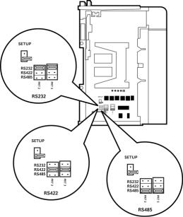
1.4Setting Jumpers
When the module is manufactured, the port selection jumpers are set to RS-232. To use RS-422 or RS-485, you must set the jumpers to the correct position. The following diagram describes the jumper settings.
The Setup Jumper acts as "write protection" for the module’s flash memory. In "write protected" mode, the Setup pins are not connected, and the module’s firmware cannot be overwritten. Do not jumper the Setup pins together unless you are directed to do so by ProSoft Technical Support.
ProSoft Technology, Inc. |
Page 15 of 167 |
March 22, 2011 |
|
Start Here |
MVI69-MCM ♦ CompactLogix or MicroLogix Platform |
User Manual |
Modbus Communication Module |
|
|
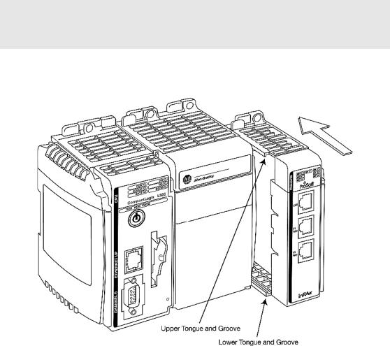
1.5Install the Module in the Rack
This section describes how to install the module into a CompactLogix or MicroLogix rack
Before you attempt to install the module, make sure that the bus lever of the adjacent module is in the unlocked (fully right) position.
Warning: This module is not hot-swappable! Always remove power from the rack before inserting or removing this module, or damage may result to the module, the processor, or other connected devices.
1Align the module using the upper and lower tongue-and-groove slots with the adjacent module and slide forward in the direction of the arrow.
2Move the module back along the tongue-and-groove slots until the bus connectors on the MVI69 module and the adjacent module line up with each other.
Page 16 of 167 |
ProSoft Technology, Inc. |
|
March 22, 2011 |
MVI69-MCM ♦ CompactLogix or MicroLogix Platform |
Start Here |
Modbus Communication Module |
User Manual |
|
|
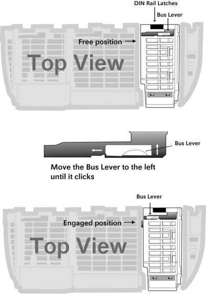
3Push the module’s bus lever back slightly to clear the positioning tab and move it firmly to the left until it clicks. Ensure that it is locked firmly in place.
4Close all DIN-rail latches.
ProSoft Technology, Inc. |
Page 17 of 167 |
March 22, 2011 |
|
Start Here |
MVI69-MCM ♦ CompactLogix or MicroLogix Platform |
User Manual |
Modbus Communication Module |
|
|
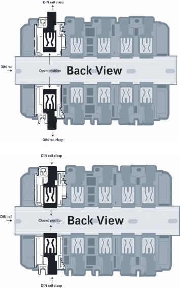
5Press the DIN-rail mounting area of the controller against the DIN-rail. The latches will momentarily open and lock into place.
Page 18 of 167 |
ProSoft Technology, Inc. |
|
March 22, 2011 |
MVI69-MCM ♦ CompactLogix or MicroLogix Platform |
Configuring the MVI69-MCM Module |
Modbus Communication Module |
User Manual |
|
|
2Configuring the MVI69-MCM Module
In This Chapter |
|
|
MVI69-MCM Sample Add-On Instruction Import Procedure.................. |
20 |
|
Using ProSoft Configuration Builder...................................................... |
46 |
|
|
Downloading the Project to the Module Using a Serial COM port ......... |
49 |
|
Module Configuration ............................................................................ |
50 |
ProSoft Technology, Inc. |
Page 19 of 167 |
March 22, 2011 |
|
Configuring the MVI69-MCM Module |
MVI69-MCM ♦ CompactLogix or MicroLogix Platform |
User Manual |
Modbus Communication Module |
|
|
2.1MVI69-MCM Sample Add-On Instruction Import Procedure
Note: this section only applies if you are using RSLogix 5000 version 16 or higher. If you are
configuring the MVI69-MCM module with an earlier version of RSLogix 5000, please refer to
Installing and Configuring the Module with a CompactLogix Processor (page 75).
The following file is required before you start this procedure. Copy the file from the ProSoft Solutions CD-ROM, or download it from www.prosoft-technology.com.
File Name Description
MVI69MCM_AddOn_Rung_v1_4.L L5X file contains the Add-On instruction, the user defined data
5x |
types, data objects and ladder logic required to set up the |
|
MVI69-MCM module |
|
|
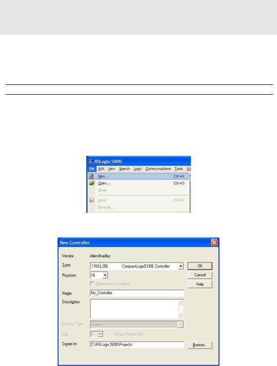
2.1.1 Create a new RSLogix5000 project
1Open the FILE menu, and then choose NEW…
2Select REVISION 16
Page 20 of 167 |
ProSoft Technology, Inc. |
|
March 22, 2011 |
MVI69-MCM ♦ CompactLogix or MicroLogix Platform |
Configuring the MVI69-MCM Module |
Modbus Communication Module |
User Manual |
|
|
2.1.2 Create the Module
1Right-click I/O CONFIGURATION and choose NEW MODULE…
2Select 1769-MODULE
3Set the Module Properties values as follows:
Parameter |
Value |
|
|
Name |
Enter a module identification string. Example: MVI69MCM |
|
|
Description |
Enter a description for the module. Example: ProSoft |
|
communication module for Serial Modbus communications. |
Comm Format |
Select Data-INT |
Slot |
Enter the slot number in the rack where the MV69-MCM |
|
module will be installed. |
Input Assembly Instance |
101 |
Input Size |
62 / 122 / 242 |
Output Assembly Instance |
100 |
Output Size |
61 / 121 / 241 |
Configuration Assembly Instance |
102 |
|
|
Configuration Size |
0 |
|
|
ProSoft Technology, Inc. |
Page 21 of 167 |
March 22, 2011 |
|

Configuring the MVI69-MCM Module |
MVI69-MCM ♦ CompactLogix or MicroLogix Platform |
User Manual |
Modbus Communication Module |
|
|
The following illustration shows an example where the module was configured for a block transfer size of 60 words (input block size = 62 words, output block size = 61 words):
The following options are available:
Block Transfer Size |
Input Block Size |
Output Block Size |
|
|
|
60 |
62 |
61 |
|
|
|
120 |
122 |
121 |
|
|
|
240 |
242 |
241 |
4On the Connection tab, set the RPI value for your project. Click OK to confirm.
Now the MVI69-MCM module will be visible at the I/O Configuration section.
Page 22 of 167 |
ProSoft Technology, Inc. |
|
March 22, 2011 |

MVI69-MCM ♦ CompactLogix or MicroLogix Platform |
Configuring the MVI69-MCM Module |
Modbus Communication Module |
User Manual |
|
|
2.1.3 Import the Ladder Rung
1Open your application in RSLogix 5000.
2To create a new routine, expand the TASKS folder, and then expand the MAIN TASK folder.
3On the MAIN PROGRAM folder, click the right mouse button to open a shortcut menu. On the shortcut menu, choose NEW ROUTINE.
4In the NEW ROUTINE dialog box, enter the name and description of your routine, and then click OK. In this example we are demonstrating the importing of the ladder rung using the default MainRoutine. In the case where you create a routine by an other name for placing the Add-On instruction, then in your original routine where your other ladder logic is located you need
to add a rung with a jump instruction to the new routine holding the Add-On instruction.
5Select an empty rung in the new routine, and then click the right mouse button to open a shortcut menu. On the shortcut menu, choose "IMPORT
RUNG…".
ProSoft Technology, Inc. |
Page 23 of 167 |
March 22, 2011 |
|
Configuring the MVI69-MCM Module |
MVI69-MCM ♦ CompactLogix or MicroLogix Platform |
User Manual |
Modbus Communication Module |
|
|
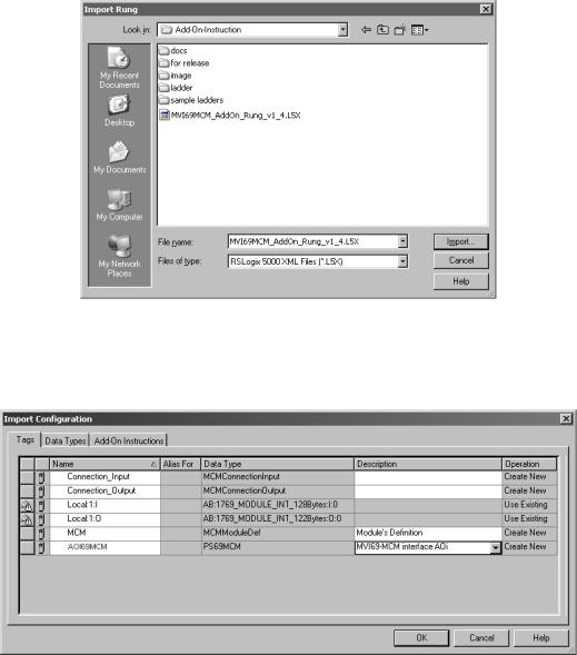
6Select the MVI69MCM_ADDON_RUNG_V1_4.L5X file
7The following window will be displayed showing the controller tags to be created during the import procedure: If desired, the description, "MVI69-MCM Interface AOI" may be typed into the description field for MVI69MCM_AddOn_Rung_v1_4.L5x file.
Page 24 of 167 |
ProSoft Technology, Inc. |
|
March 22, 2011 |
MVI69-MCM ♦ CompactLogix or MicroLogix Platform |
Configuring the MVI69-MCM Module |
Modbus Communication Module |
User Manual |
|
|
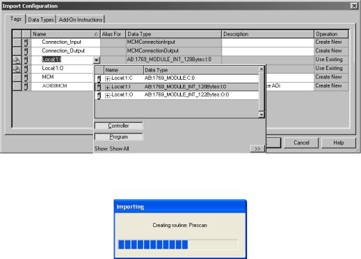
8If you are using the module in a different slot (or remote rack) select the correct connection input and output variables associated to the module. If your module is located in slot 1 of the local rack this step is not required.
9Click OK to confirm the import. RSLogix will indicate that the import is under progress:
ProSoft Technology, Inc. |
Page 25 of 167 |
March 22, 2011 |
|
Configuring the MVI69-MCM Module |
MVI69-MCM ♦ CompactLogix or MicroLogix Platform |
User Manual |
Modbus Communication Module |
|
|
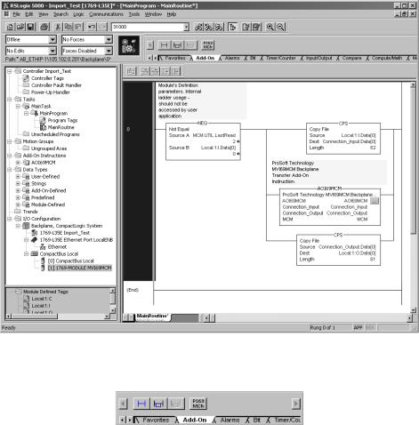
When the import is completed, the new rung with the Add-On instruction will be visible as shown in the following illustration.
The procedure has also imported new user defined data types, data objects and the Add-On instruction to be used at your project.
Page 26 of 167 |
ProSoft Technology, Inc. |
|
March 22, 2011 |

MVI69-MCM ♦ CompactLogix or MicroLogix Platform |
Configuring the MVI69-MCM Module |
Modbus Communication Module |
User Manual |
|
|
10The imported rung will contain the Add-On instruction with two CPS instructions as follows below. The CPS instructions are set by default for a length of 62/61 words as follows:
Edit the above CPS instructions Length field values according to the following table.
"Block Transfer Size Parameter" – |
Ladder Routine window: |
|
|
60/120/240 options) |
|
|
|
|
|
||
Connection Parameters: |
CPS instructions Length field values: |
||
|
|
|
|
Input Size: |
Output Size: |
|
|
|
|
|
|
62 |
61 |
62 |
61 |
|
|
|
|
122 |
121 |
122 |
121 |
|
|
|
|
242 |
241 |
242 |
241 |
|
|
|
|
2.1.4 Set the Read/Write Data Lengths
1The imported rung contains the MCMDATA object Tag arrays READDATA and WRITEDATA set to the factory default values of 480. These tags will contain:
o READDATA - data area copied from the module to the processor o WRITEDATA - data area copied from the processor to the module
ProSoft Technology, Inc. |
Page 27 of 167 |
March 22, 2011 |
|

Configuring the MVI69-MCM Module |
MVI69-MCM ♦ CompactLogix or MicroLogix Platform |
User Manual |
Modbus Communication Module |
|
|
2If you have changed the READ REGISTER COUNT and WRITE REGISTER COUNT
values in the [BACKPLANE 69] section of the module’s configuration file, you must adjust these array sizes to match those values.
Example: If in the configuration file section [Backplane 69] the parameter setting is "Read Register Count : 1440" then set ReadData tag array size to INT[1440].
Page 28 of 167 |
ProSoft Technology, Inc. |
|
March 22, 2011 |

MVI69-MCM ♦ CompactLogix or MicroLogix Platform |
Configuring the MVI69-MCM Module |
Modbus Communication Module |
User Manual |
|
|
Example: If in the configuration file section [Backplane 69] the parameter setting is "Write Register Count : 1880" then set WriteData tag array size to INT[1880].
You will be prompted to confirm the changes. Click Yes to continue.
2.1.5 Set the Block Transfer Parameter Size
The MCM.BLOCKTRANSFERSIZE controller tag is set to 60 in the Add-On Instruction. If you have configured a different block transfer size in the module’s configuration file, you must change this value to match.
Edit the tag values according to the following table.
ProSoft Technology, Inc. |
Page 29 of 167 |
March 22, 2011 |
|

Configuring the MVI69-MCM Module |
MVI69-MCM ♦ CompactLogix or MicroLogix Platform |
|||
User Manual |
|
Modbus Communication Module |
||
|
|
|
|
|
|
|
|
|
|
|
Module Properties dialog box: |
Controller Organizer’s Controller Tags folder: |
||
|
|
|
|
|
|
Connection Parameters: |
MCM.BlockTransferSize tag value: |
||
|
|
|
|
|
|
Input Size: |
Output Size: |
|
|
|
|
|
|
|
62 |
61 |
60 |
|
|
|
|
|
|
|
122 |
121 |
120 |
|
|
|
|
|
|
|
242 |
241 |
240 |
|
|
|
|
|
|
|
2.1.6 Set the Connection Input Size Values
If you change the block transfer size, you must also change the following data types:
MCMCONNECTIONINPUT – Data type used for the Connection Input pin in the Add-On instruction.
MCMCONNECTIONOUTPUT – Data type used for the Connection Output pin in the Add-On instruction.
Access the user data type definition MCMCONNECTIONINPUT as follows
Edit the tag values according to the following table.
Module Properties dialog box: |
Controller Organizer’s Controller Tags folder: |
|
|
Connection Parameters: |
MCMConnectionInput.Data tag value: |
|
|
Input Size: |
|
|
|
62 |
62 |
|
|
122 |
122 |
|
|
242 |
242 |
|
|
Page 30 of 167 |
ProSoft Technology, Inc. |
|
March 22, 2011 |
 Loading...