


 Loading...
MVI56E-SIE
ControlLogix Platform
Siemens Industrial Ethernet
Client Communication Module
September 6, 2012
USER MANUAL
Your Feedback Please
We always want you to feel that you made the right decision to use our products. If you have suggestions, comments, compliments or complaints about our products, documentation, or support, please write or call us.
How to Contact Us
ProSoft Technology
5201 Truxtun Ave., 3rd Floor Bakersfield, CA 93309
+1 (661) 716-5100
+1 (661) 716-5101 (Fax) www.prosoft-technology.com support@prosoft-technology.com
Copyright © 2012 ProSoft Technology, Inc., all rights reserved.
MVI56E-SIE User Manual
September 6, 2012
ProSoft Technology ®, ProLinx ®, inRAx ®, ProTalk ®, and RadioLinx ® are Registered Trademarks of ProSoft Technology, Inc. All other brand or product names are or may be trademarks of, and are used to identify products and services of, their respective owners.
ProSoft Technology® Product Documentation
In an effort to conserve paper, ProSoft Technology no longer includes printed manuals with our product shipments. User Manuals, Datasheets, Sample Ladder Files, and Configuration Files are provided on the enclosed CD-ROM in Adobe® Acrobat Reader file format (.PDFs). These product documentation files may also be freely downloaded from our web site: www.prosoft-technology.com

Important Safety Information
North America Warnings
AWarning - Explosion Hazard - Substitution of components may impair suitability for Class I, Division 2.
BWarning - Explosion Hazard - When in hazardous locations, turn off power before replacing or rewiring modules. Warning - Explosion Hazard - Do not disconnect equipment unless power has been switched off or the area is known to be nonhazardous.
CSuitable for use in Class I, Division 2 Groups A, B, C, and D, T5 Hazardous Locations or Non-Hazardous Locations.
ATEX Warnings and Conditions of Safe Usage
Power, Input, and Output (I/O) wiring must be in accordance with the authority having jurisdiction
AWarning - Explosion Hazard - When in hazardous locations, turn off power before replacing or wiring modules.
BWarning - Explosion Hazard - Do not disconnect equipment unless power has been switched off or the area is known to be non-hazardous.
CThese products are intended to be mounted in an IP54 enclosure. The devices shall provide external means to prevent the rated voltage being exceeded by transient disturbances of more than 40%. This device must be used only with ATEX certified backplanes.
DDO NOT OPEN WHEN ENERGIZED.
Electrical Ratings
Backplane Current Load: 800 mA @ 5 Vdc; 3 mA @ 24 Vdc
Operating Temperature: 0°C to 60°C (32°F to 140°F)
Storage Temperature: -40°C to 85°C (-40°F to 185°F)
Shock: 30 g operational; 50 g non-operational; Vibration: 5 g from 10 Hz to 150 Hz
Relative Humidity 5% to 95% (without condensation)
All phase conductor sizes must be at least 1.3 mm (squared) and all earth ground conductors must be at least 4mm (squared).
Markings
RoHS
CE
MVI56E-SIE ♦ ControlLogix Platform |
Contents |
Client Communication Module |
User Manual |
|
|
Contents
|
|
Your Feedback Please........................................................................................................................ |
2 |
||
|
|
How to Contact Us .............................................................................................................................. |
2 |
||
|
|
ProSoft Technology® Product Documentation .................................................................................... |
2 |
||
|
|
Important Safety Information............................................................................................................... |
3 |
||
|
Guide to the MVI56E-SIE User Manual |
9 |
|||
|
|
|
|
|
|
1 |
Start Here |
|
11 |
||
|
|
|
|
|
|
|
|
1.1 |
Features .................................................................................................................. |
12 |
|
|
|
1.2 |
System Requirements ............................................................................................. |
13 |
|
|
|
1.3 |
Package Contents ................................................................................................... |
14 |
|
|
|
1.4 |
Setting Jumpers ...................................................................................................... |
15 |
|
|
|
1.5 |
Installing the Module in the Rack ............................................................................ |
16 |
|
|
|
1.6 |
Importing the Sample Add-On Instruction ............................................................... |
18 |
|
|
|
1.7 |
Creating a New RSLogix 5000 Project.................................................................... |
19 |
|
|
|
1.7.1 |
Creating the Module ................................................................................................ |
20 |
|
|
|
1.7.2 |
Importing the Add-On Instruction ............................................................................ |
22 |
|
|
|
1.8 |
Connecting Your PC to the ControlLogix Processor ............................................... |
35 |
|
|
|
1.9 |
Downloading the Sample Program to the Processor .............................................. |
36 |
|
2 |
Configuring the MVI56E-SIE Module |
37 |
|||
|
|
|
|
|
|
|
|
2.1 |
Installing ProSoft Configuration Builder .................................................................. |
38 |
|
|
|
2.2 |
Using ProSoft Configuration Builder Software ........................................................ |
39 |
|
|
|
2.2.1 |
Setting Up the Project ............................................................................................. |
39 |
|
|
|
2.2.2 |
Setting Module Parameters..................................................................................... |
42 |
|
|
|
2.2.3 |
Module..................................................................................................................... |
44 |
|
|
|
2.2.4 |
SIE Client x.............................................................................................................. |
47 |
|
|
|
2.2.5 |
SIE Client x Commands .......................................................................................... |
49 |
|
|
|
2.2.6 |
Configuration Examples .......................................................................................... |
70 |
|
|
|
2.2.7 |
Static ARP Table ..................................................................................................... |
85 |
|
|
|
2.2.8 |
Ethernet Configuration ............................................................................................ |
86 |
|
|
|
2.3 |
Connecting Your PC to the Module......................................................................... |
87 |
|
|
|
2.3.1 |
Setting Up a Temporary IP Address ....................................................................... |
87 |
|
|
|
2.4 |
Downloading the Project to the Module .................................................................. |
91 |
|
|
|
2.4.1 |
Using CIPconnect to Connect to the Module .......................................................... |
92 |
|
|
|
2.4.2 |
Using RSWho to Connect to the Module .............................................................. |
102 |
|
3 |
Ladder Logic |
103 |
|||
|
|
|
|
|
|
|
|
3.1 |
Controller Tags ...................................................................................................... |
104 |
|
|
|
3.1.1 |
MVI56E-SIE Controller Tags ................................................................................. |
104 |
|
|
|
3.2 |
User-Defined Data Types (UDTs) ......................................................................... |
106 |
|
|
|
3.2.1 |
MVI56E-SIE User-Defined Data Types................................................................. |
106 |
|
|
|
3.3 |
Using Controller Tags............................................................................................ |
107 |
|
|
|
|
|
|
|
ProSoft Technology, Inc. |
|
Page 5 of 168 |
|||
September 6, 2012 |
|
|
|
||
Contents |
|
MVI56E-SIE ♦ ControlLogix Platform |
|||
User Manual |
|
Client Communication Module |
|||
|
|
|
|
|
|
3.4 |
|
Controller Tag Overview ....................................................................................... |
108 |
||
|
|
3.4.1 |
SIE.DATA.............................................................................................................. |
108 |
|
|
|
3.4.2 |
SIE.CONTROL...................................................................................................... |
111 |
|
|
|
3.4.3 |
SIE.STATUS ......................................................................................................... |
111 |
|
|
|
3.4.4 |
SIE.UTIL ............................................................................................................... |
112 |
|
4 |
Diagnostics and Troubleshooting |
113 |
|||
|
|
|
|
|
|
4.1 |
|
LED Status Indicators ........................................................................................... |
114 |
||
|
|
4.1.1 |
Scrolling LED Status Indicators ............................................................................ |
114 |
|
|
|
4.1.2 |
Ethernet LED Indicators........................................................................................ |
115 |
|
|
|
4.1.3 |
Non-Scrolling LED Status Indicators .................................................................... |
115 |
|
|
|
4.1.4 |
Troubleshooting .................................................................................................... |
116 |
|
|
|
4.1.5 |
Clearing a Fault Condition .................................................................................... |
117 |
|
4.2 |
|
Using the Diagnostics Menu in ProSoft Configuration Builder ............................. |
118 |
||
|
|
4.2.1 |
Connecting to the Module's Web Page ................................................................ |
120 |
|
|
|
4.2.2 |
The Diagnostics Menu .......................................................................................... |
121 |
|
|
|
4.2.3 |
Monitoring Module Information ............................................................................. |
122 |
|
|
|
4.2.4 |
Monitoring Backplane Information ........................................................................ |
123 |
|
|
|
4.2.5 |
Monitoring Database Information.......................................................................... |
124 |
|
|
|
4.2.6 |
Monitoring SIE Client Information ......................................................................... |
125 |
|
4.3 |
|
Reading Status Data from the Module ................................................................. |
126 |
||
|
|
4.3.1 |
Status Data Definition ........................................................................................... |
127 |
|
|
|
4.3.2 |
Configuration Error Word...................................................................................... |
129 |
|
|
|
4.3.3 |
Client Command Errors ........................................................................................ |
130 |
|
5 |
Reference |
|
133 |
||
|
|
|
|
|
|
5.1 |
|
Product Specifications .......................................................................................... |
134 |
||
|
|
5.1.1 |
General Specifications .......................................................................................... |
134 |
|
|
|
5.1.2 |
Functional Specifications ...................................................................................... |
135 |
|
|
|
5.1.3 |
Hardware Specifications ....................................................................................... |
135 |
|
5.2 |
|
Backplane Data Transfer ...................................................................................... |
136 |
||
|
|
5.2.1 |
Normal Data Transfer Blocks................................................................................ |
138 |
|
|
|
5.2.2 |
Special Function Blocks........................................................................................ |
142 |
|
|
|
5.2.3 |
Client Driver .......................................................................................................... |
150 |
|
|
|
5.2.4 |
Client Command List ............................................................................................ |
151 |
|
5.3 |
|
Ethernet Cable Specifications............................................................................... |
152 |
||
|
|
5.3.1 |
Ethernet Cable Configuration ............................................................................... |
152 |
|
|
|
5.3.2 |
Ethernet Performance........................................................................................... |
153 |
|
5.4 |
|
Using the Optional Add-On Instruction Rung Import ............................................ |
154 |
||
|
|
5.4.1 |
Before Beginning ................................................................................................. |
154 |
|
|
|
5.4.2 |
Overview ............................................................................................................... |
154 |
|
|
|
5.4.3 |
Installing the Rung Import with Optional Add-On Instruction................................ |
155 |
|
|
|
5.4.4 |
Reading the Ethernet Settings from the Module................................................... |
159 |
|
|
|
5.4.5 |
Writing the Ethernet Settings to the Module ......................................................... |
161 |
|
|
|
5.4.6 |
Reading the Clock Value from the Module ........................................................... |
163 |
|
|
|
5.4.7 |
Writing the Clock Value to the Module ................................................................. |
164 |
|
6 |
Support, Service and Warranty |
165 |
|||
|
|
|
|
|
|
6.1 |
|
Contacting Technical Support............................................................................... |
165 |
||
6.2 |
|
Warranty Information ............................................................................................ |
166 |
||
|
|
|
|
||
Page 6 of 168 |
ProSoft Technology, Inc. |
||||
|
|
|
|
September 6, 2012 |
|

MVI56E-SIE ♦ ControlLogix Platform |
Contents |
||
Client Communication Module |
User Manual |
||
|
|
|
|
|
Index |
167 |
|
|
|
|
|
ProSoft Technology, Inc. |
Page 7 of 168 |
September 6, 2012 |
|

Contents |
MVI56E-SIE ♦ ControlLogix Platform |
User Manual |
Client Communication Module |
|
|
Page 8 of 168 |
ProSoft Technology, Inc. |
|
September 6, 2012 |
MVI56E-SIE ♦ ControlLogix Platform |
Guide to the MVI56E-SIE User Manual |
Client Communication Module |
User Manual |
|
|
Guide to the MVI56E-SIE User Manual
Function
Introduction
(Must Do)
Diagnostic and
Troubleshooting
Reference
Product Specifications
Support, Service, and
Warranty
Section to Read |
Details |
|
|
|
|
Start Here (page 11) |
This section introduces the customer to |
|
the module. Included are: package |
|
contents, system requirements, |
|
hardware installation, and basic |
|
configuration. |
|
|
|
|
Diagnostics and |
This section describes Diagnostic and |
Troubleshooting |
Troubleshooting procedures. |
|
|
(page 113) |
|
|
|
|
|
Reference (page |
These sections contain general |
133) |
references associated with this product |
|
and its Specifications.. |
Product |
|
Specifications (page |
|
134) |
|
|
|
|
|
Support, Service |
This section contains Support, Service |
and Warranty (page |
and Warranty information. |
165) |
|
Index |
Index |
Index of chapters. |
ProSoft Technology, Inc. |
Page 9 of 168 |
September 6, 2012 |
|

Guide to the MVI56E-SIE User Manual |
MVI56E-SIE ♦ ControlLogix Platform |
User Manual |
Client Communication Module |
|
|
Page 10 of 168 |
ProSoft Technology, Inc. |
|
September 6, 2012 |
MVI56E-SIE ♦ ControlLogix Platform |
Start Here |
Client Communication Module |
User Manual |
|
|
1 |
Start Here |
|
|
|
In This Chapter |
|
|
|
|
What's New? ......................................................................................... |
12 |
|
|
System Requirements ........................................................................... |
13 |
|
|
Package Contents ................................................................................. |
14 |
|
|
Setting Jumpers .................................................................................... |
15 |
|
Installing the Module in the Rack........................................................... |
16 |
|
|
Importing the Sample Add-On Instruction.............................................. |
18 |
|
|
Creating a New RSLogix 5000 Project .................................................. |
19 |
|
|
Connecting Your PC to the ControlLogix Processor.............................. |
35 |
|
|
Downloading the Sample Program to the Processor ............................. |
36 |
|
To get the most benefit from this User Manual, the following skills will be needed:
Rockwell Automation® RSLogix™ software: launch the program, configure ladder logic, and transfer the ladder logic to the processor
Microsoft Windows: install and launch programs, execute menu commands, navigate dialog boxes, and enter data
Hardware installation and wiring: install the module, and safely connect Siemens Industrial Ethernet and ControlLogix devices to a power source and to the MVI56E-SIE module’s application port(s)
ProSoft Technology, Inc. |
Page 11 of 168 |
September 6, 2012 |
|

Start Here |
MVI56E-SIE ♦ ControlLogix Platform |
User Manual |
Client Communication Module |
|
|
1.1Features
.
ProSoft Configuration Builder (PCB): Windows-based software for diagnostics, connecting via the module's Ethernet port or CIPconnect®, to upload/download module configuration information and access troubleshooting features and functions.
ProSoft Discovery Service (PDS): Utility software to find and display a list of MVI56E modules on the network and to temporarily change an IP address to connect with a module's web page.
CIPconnect-enabled: Allows PC-to-module configuration and diagnostics from the Ethernet network through a ControlLogix 1756-ENBT EtherNet/IP™ module.
Personality Module: An industrial compact flash memory card storing the module’s complete configuration and Ethernet settings, allowing quick and easy replacement.
LED Scrolling Diagnostic Display: 4-character, alphanumeric display, providing messages for status and alarm data, and for processor and network communication status.
Page 12 of 168 |
ProSoft Technology, Inc. |
|
September 6, 2012 |

MVI56E-SIE ♦ ControlLogix Platform |
Start Here |
Client Communication Module |
User Manual |
|
|
1.2System Requirements
The MVI56E-SIE module requires the following minimum hardware and software components:
Rockwell Automation ControlLogix® processor (firmware version 16 or higher), with compatible power supply, and one free slot in the rack for the MVI56E-SIE module. The module requires 800 mA of available 5 Vdc power
Rockwell Automation RSLogix 5000 programming software o Version 16 or higher required for Add-On Instruction
Rockwell Automation RSLinx® communication software version 2.51 or higher
ProSoft Configuration Builder (PCB) (included)
ProSoft Discovery Service (PDS) (included in PCB)
Pentium® II 450 MHz minimum. Pentium III 733 MHz (or better) recommended
Supported operating systems: o Microsoft Windows® Vista
o Microsoft Windows XP Professional with Service Pack 1 or 2
o Microsoft Windows 2000 Professional with Service Pack 1, 2, or 3 o Microsoft Windows Server 2003
o Microsoft Windows 7
128 Mbytes of RAM minimum, 256 Mbytes of RAM recommended
100 Mbytes of free hard disk space (or more based on application
requirements)
256-color VGA graphics adapter, 800 x 600 minimum resolution (True Color 1024 768 recommended)
CD-ROM drive/DVD drive
Note: The Hardware and Operating System requirements in this list are the minimum recommended to install and run software provided by ProSoft Technology®. Other third party applications may have different minimum requirements. Refer to the documentation for any third party applications for system requirements.
Note: The module can be installed in a local or remote rack. For remote rack installation, the module requires EtherNet/IP or ControlNet communication with the processor.
|
|
|
|
|
|
|
|
ProSoft Technology, Inc. |
Page 13 of 168 |
||
September 6, 2012 |
|
|
|

Start Here |
MVI56E-SIE ♦ ControlLogix Platform |
User Manual |
Client Communication Module |
|
|
1.3Package Contents
The following components are included with your MVI56E-SIE module, and are all required for installation and configuration.
Important: Before beginning the installation, please verify that all of the following items are present.
|
|
|
|
|
|
|
|
|
|
|
|
|
Qty. |
Part Name |
Part Number |
Part Description |
|
1 |
MVI56E-SIE Module |
MVI56E-SIE |
Siemens Industrial Ethernet Client |
||
|
|
|
|
Communication Module |
|
|
|
|
|
|
|
1 |
Cable |
RL-CBL025 |
5-foot Ethernet Straight-Through Cable |
||
|
|
|
|
(Gray) |
|
|
|
|
|
|
|
1 |
ProSoft Solutions CD |
CD-001 |
Contains configuration tools for the |
||
|
|
OR |
|
MVI56E-SIE module |
|
|
|
ProSoft Solutions |
DVD-001 |
|
|
|
|
DVD |
|
|
|
If any of these components are missing, please contact ProSoft Technology Support for replacement parts.
Page 14 of 168 |
ProSoft Technology, Inc. |
|
September 6, 2012 |
MVI56E-SIE ♦ ControlLogix Platform |
Start Here |
Client Communication Module |
User Manual |
|
|
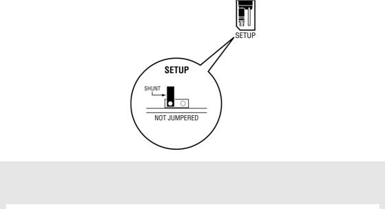
1.4Setting Jumpers
The Setup Jumper acts as "write protection" for the module’s flash memory. In "write protected" mode, the Setup pins are not connected, and the module’s firmware cannot be overwritten. Do not jumper the Setup pins together unless you are directed to do so by ProSoft Technical Support.
The following illustration shows the MVI56E-SIE jumper configuration.
Note: If the module is being installed in a remote rack, the Setup pins can be left jumpered. That way, the module’s firmware can be updated without requiring physical access to the module.
|
|
|
|
|
|
|
|
ProSoft Technology, Inc. |
Page 15 of 168 |
||
September 6, 2012 |
|
|
|
Start Here |
MVI56E-SIE ♦ ControlLogix Platform |
User Manual |
Client Communication Module |
|
|
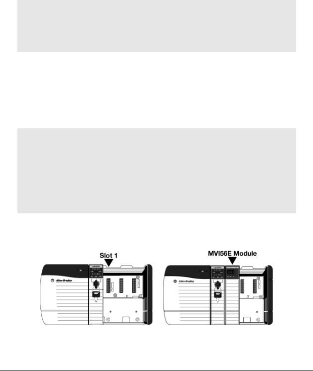
1.5Installing the Module in the Rack
If the ControlLogix processor and power supply have not already been installed and configured, please do so before installing the MVI56E-SIE module. Refer to the Rockwell Automation product documentation for installation instructions.
Warning: All safety instructions must be followed when installing this or any other electronic devices. Failure to follow safety procedures could result in damage to hardware or data, or even serious injury or death to personnel. Refer to the documentation for each device that will be connected to verify that suitable safety procedures are in place before installing or servicing the device.
After the placement of the jumpers has been checked, insert the MVI56E-SIE into the ControlLogix chassis. Use the same technique recommended by Rockwell Automation to remove and install ControlLogix modules.
ControlLogix system components can be installed or removed while chassis power is applied and the system is operating. However, please note the following warning.
Warning: When the module is inserted or removed while backplane power is on, an electrical arc can occur. An electrical arc can cause personal injury or property damage by sending an erroneous signal to the system’s actuators. This can cause unintended machine motion or loss of process control. Electrical arcs may also cause an explosion when they happen in a hazardous environment. Verify that power is removed or the area is non-hazardous before proceeding. Repeated electrical arcing causes excessive wear to contacts on both the module and its mating connector. Worn contacts may create electrical resistance that can affect module operation.
1Align the module with the top and bottom guides, and then slide it into the rack until the module is firmly against the backplane connector.
2With a firm, steady push, snap the module into place.
3Check that the holding clips on the top and bottom of the module are securely in the locking holes of the rack.
Page 16 of 168 |
ProSoft Technology, Inc. |
|
September 6, 2012 |

MVI56E-SIE ♦ ControlLogix Platform |
Start Here |
Client Communication Module |
User Manual |
|
|
4Make a note of the slot location. The slot in which the module is installed in must be indentified in order for the sample program to work correctly. Slot numbers are identified on the green circuit board (backplane) of the ControlLogix rack.
5Turn power ON.
Note: If the module is inserted improperly, the system may stop working or may behave unpredictably.
|
|
|
|
|
|
|
|
ProSoft Technology, Inc. |
Page 17 of 168 |
||
September 6, 2012 |
|
|
|

Start Here |
MVI56E-SIE ♦ ControlLogix Platform |
User Manual |
Client Communication Module |
|
|
1.6Importing the Sample Add-On Instruction
Note: This section only applies if the processor is using RSLogix 5000 version 16 or higher. If an earlier version is installed, please contact ProSoft Technology for more information.
Before You Begin
Two Add-On Instructions are provided for the MVI56E-SIE module. The first is required for setting up the module; the second is optional.
Copy the files from the ProSoft Solutions CD-ROM or Prosoft Solutions DVD or download them from www.prosoft-technology.com. Save them to a convenient location in your PC, such as Desktop or My Documents.
File Name |
Description |
MVI56ESIE_AddOn_Rung_v1_0.L5X |
L5X file containing Add-On Instruction, user defined |
|
data types, controller tags and ladder logic required |
|
to configure the MVI56E-SIE module |
|
|
MVI56ESIE_Optional_Rung_v1_0.L5X |
Optional L5X file containing additional Add-On |
|
Instruction with logic for changing Ethernet |
|
configuration and clock settings. |
|
|
Page 18 of 168 |
ProSoft Technology, Inc. |
|
September 6, 2012 |
MVI56E-SIE ♦ ControlLogix Platform |
Start Here |
Client Communication Module |
User Manual |
|
|
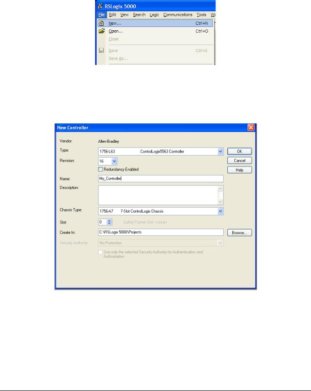
1.7Creating a New RSLogix 5000 Project
1 Open the FILE menu, and then choose NEW.
2Select the ControlLogix controller model.
3Select REVISION 16.
4Enter a name forthe controller, such as My_Controller.
5Select theControlLogix chassis type.
6Select SLOT 0 for the controller.
ProSoft Technology, Inc. |
Page 19 of 168 |
September 6, 2012 |
|
Start Here |
MVI56E-SIE ♦ ControlLogix Platform |
User Manual |
Client Communication Module |
|
|
1.7.1 Creating the Module
1Add the MVI56E-SIE module to the project.
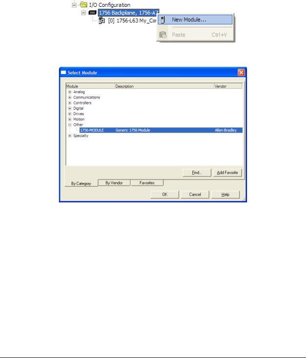
In the Controller Organization window, select I/O CONFIGURATION and click the right mouse button to open a shortcut menu. On the shortcut menu, choose NEW MODULE.
This action opens the Select Module dialog box.
2Select the 1756-MODULE (GENERIC 1756 MODULE) from the list and click OK. This action opens the New Module dialog box.
Page 20 of 168 |
ProSoft Technology, Inc. |
|
September 6, 2012 |
MVI56E-SIE ♦ ControlLogix Platform |
Start Here |
Client Communication Module |
User Manual |
|
|
3 In the New Module dialog box, enter the following values.
|
Parameter |
Value |
|
|
Name |
Enter a module identification string. Example: SIE |
|
|
Description |
Enter a description for the module. Example: SIEMENS |
|
|
INDUSTRIAL ETHERNET CLIENT COMMUNICATION MODULE |
||
|
|
||
|
|
|
|
|
Comm Format |
Select DATA-INT. |
|
|
|
|
|
|
Slot |
Enter the slot number in the rack where the MVI56E-SIE |
|
|
|
module is located. |
|
|
|
|
|
|
Input Assembly Instance |
1 |
|
|
|
|
|
|
Input Size |
250 |
|
|
|
|
|
|
Output Assembly Instance |
2 |
|
|
|
|
|
|
Output Size |
248 |
|
|
|
|
|
|
Configuration Assembly Instance |
4 |
|
|
|
|
|
|
Configuration Size |
0 |
|
|
|
|
|
|
|
|
|
|
|
|
|
Important: The Comm Format DATA – INTmust be selected in the dialog box, otherwise the module will not communicate over the backplane of the ControlLogix rack.
4Click OK to continue.
5Edit the Module Properties. Select the Requested Packet Interval value for scanning the I/O on the module. This value represents the minimum frequency at which the module will handle scheduled events. This value should not be set to less than 1 millisecond. The default value is 5 milliseconds. Values between 1 and 10 milliseconds should work with most applications.
6 Save the module.
ProSoft Technology, Inc. |
Page 21 of 168 |
September 6, 2012 |
|
Start Here |
MVI56E-SIE ♦ ControlLogix Platform |
User Manual |
Client Communication Module |
|
|
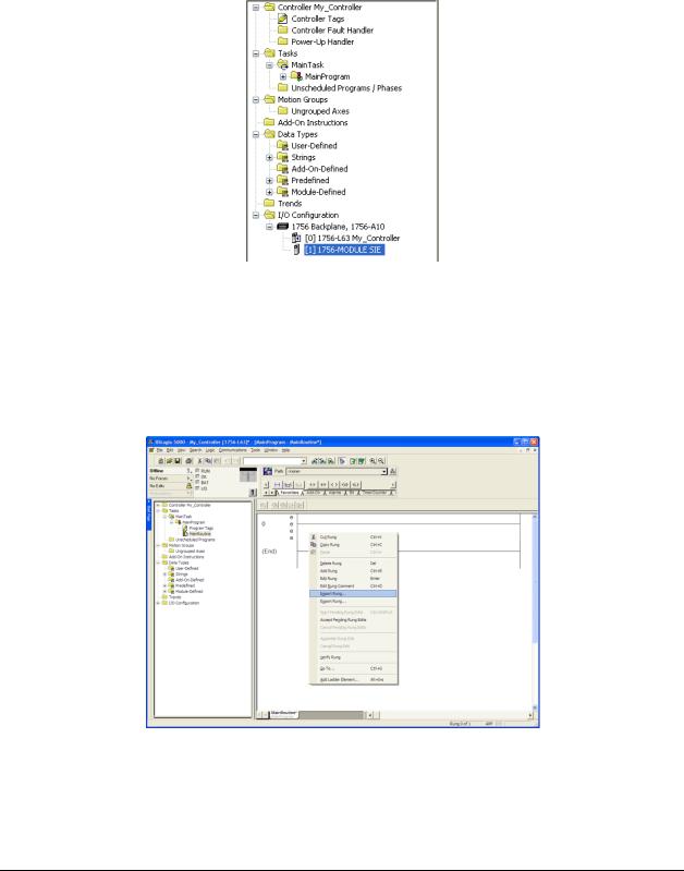
Click OK to close the dialog box. Notice that the module now appears in the
Controller Organization window.
1.7.2 Importing the Add-On Instruction
1In the Controller Organization window, expand the TASKS folder and subfolder until the MAINPROGRAM folder is reached.
2In the MAINPROGRAM folder, double-click to open the MAINROUTINE ladder.
3Select an empty rung in the new routine, and then click the right mouse button to open a shortcut menu. On the shortcut menu, choose IMPORT RUNG.
Page 22 of 168 |
ProSoft Technology, Inc. |
|
September 6, 2012 |

MVI56E-SIE ♦ ControlLogix Platform |
Start Here |
Client Communication Module |
User Manual |
|
|
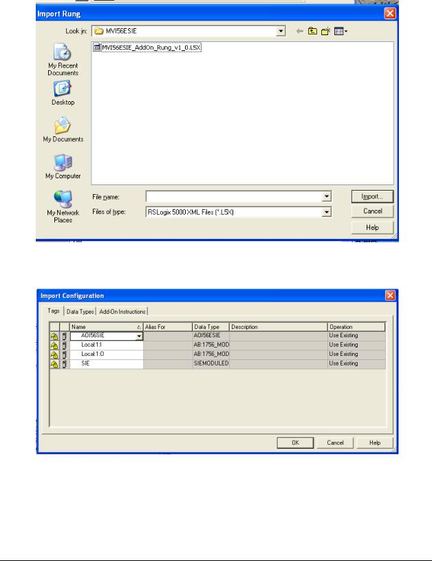
4Navigate to the location on the PC where the Add-On Instruction was saved (for example, My Documents or Desktop). Select the
MVI56ESIE_ADDON_RUNG_V1_0.L5X file.
This action opens the Import Configuration dialog box. Clicking on Tags
Reference will show the controller tags that will be created.
5If the module is being used in a different slot (or remote rack), select the correct connection input and output variables that define the path to the module. If the module is located in Slot 1 of the local rack, this step is not required.
ProSoft Technology, Inc. |
Page 23 of 168 |
September 6, 2012 |
|

Start Here |
MVI56E-SIE ♦ ControlLogix Platform |
User Manual |
Client Communication Module |
|
|
6Click OK to confirm the import. RSLogix will indicate that the import is in progress:
When the import is completed, the new rung with the Add-On Instruction will be visible as shown in the following illustration.
The procedure has also imported new user-defined data types, data objects and the Add-On Instruction for your project.
7Save the application and then download the sample ladder logic to the processor.
Page 24 of 168 |
ProSoft Technology, Inc. |
|
September 6, 2012 |
MVI56E-SIE ♦ ControlLogix Platform |
Start Here |
||
Client Communication Module |
User Manual |
||
|
|
|
|
|
Adding Multiple Modules (Optional) |
|
|
|
|
|
|
|
|
|
|
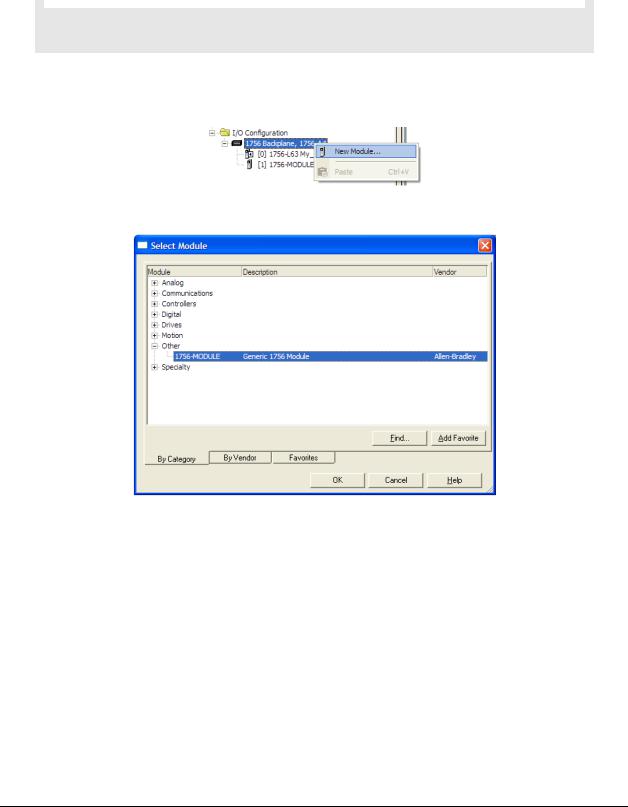
Important: If the application requires more than one MVI56-SIE module in the same project, follow the steps below.
1In the I/O CONFIGURATION folder, click the right mouse button to open a shortcut menu, and then choose NEW MODULE.
2Select 1756-MODULE.
3 Fill the module properties as follows:
Parameter |
Value |
Name |
Enter a module identification string. Example: SIE_2. |
|
|
Description |
Enter a description for the module. Example: SIEMENS |
|
INDUSTRIAL ETHERNET CLIENT COMMUNICATION MODULE |
|
|
Comm Format |
Select DATA-INT. |
Slot |
Enter the slot number in the rack where the MVI56E-SIE |
|
module is located. |
|
|
Input Assembly Instance |
1 |
Input Size |
250 |
Output Assembly Instance |
2 |
Output Size |
248 |
Configuration Assembly Instance |
4 |
Configuration Size |
0 |
ProSoft Technology, Inc. |
Page 25 of 168 |
September 6, 2012 |
|
Start Here |
MVI56E-SIE ♦ ControlLogix Platform |
User Manual |
Client Communication Module |
|
|
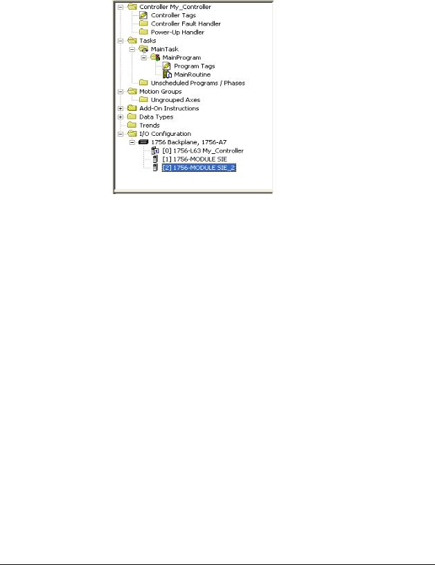
4 Click OK to confirm. The new module is now visible:
5Expand the TASKS folder, and then expand the MAINTASK folder.
6In the MAINPROGRAM folder, double-click to open the MAINROUTINE ladder.
Page 26 of 168 |
ProSoft Technology, Inc. |
|
September 6, 2012 |

MVI56E-SIE ♦ ControlLogix Platform |
Start Here |
Client Communication Module |
User Manual |
|
|
7Select an empty rung in the routine, and then click the right mouse button to open a shortcut menu. On the shortcut menu, choose IMPORT RUNG.
ProSoft Technology, Inc. |
Page 27 of 168 |
September 6, 2012 |
|
Start Here |
MVI56E-SIE ♦ ControlLogix Platform |
User Manual |
Client Communication Module |
|
|
8 Select the MVI56ESIE_ADDON_RUNG_V1_0.L5X file, and then click IMPORT.
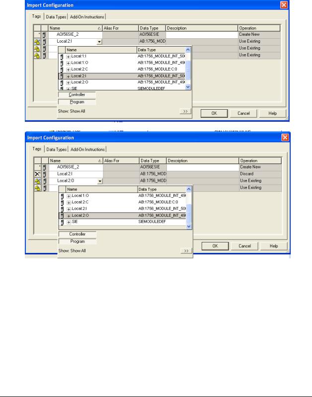
9This action opens the Import Configuration window, which shows the tags that will be imported.
Page 28 of 168 |
ProSoft Technology, Inc. |
|
September 6, 2012 |
MVI56E-SIE ♦ ControlLogix Platform |
Start Here |
Client Communication Module |
User Manual |
|
|
10Associate the I/O connection variables to the correct module. The default values are Local:1:I and Local:1:O so these require change.
ProSoft Technology, Inc. |
Page 29 of 168 |
September 6, 2012 |
|
Start Here |
MVI56E-SIE ♦ ControlLogix Platform |
User Manual |
Client Communication Module |
|
|
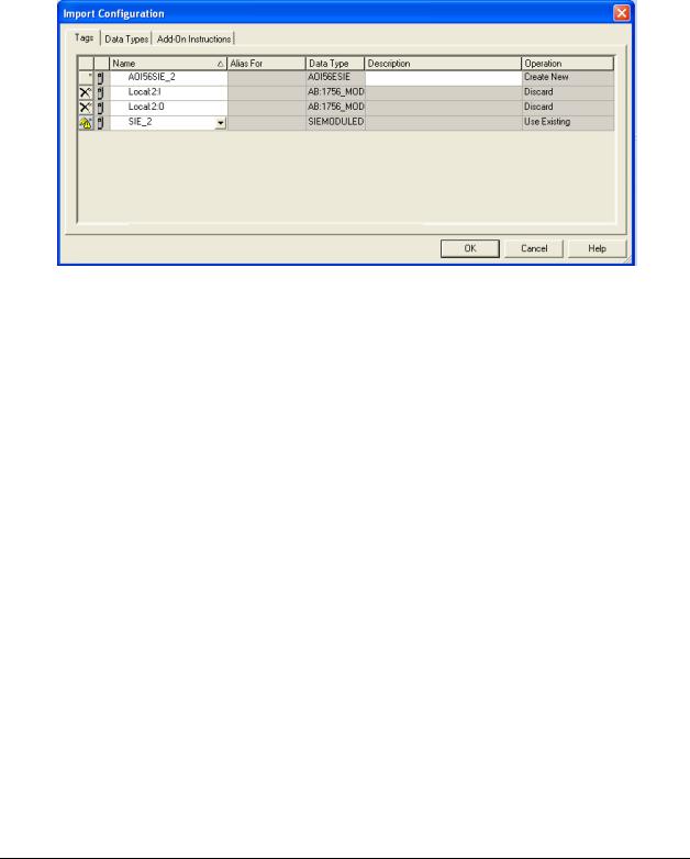
11Change the default tags SIE and AOI56SIE to avoid conflict with existing tags. In this step, you should append a string to the default tag names, such as "_2", as shown in the following illustration.
Page 30 of 168 |
ProSoft Technology, Inc. |
|
September 6, 2012 |
Loading...