


ILX34-MBS
User Manual
Modbus Serial Module for
CompactLogix L1 and Point I/O
Adapters
February 18, 2015
USER MANUAL

User Manual
Your Feedback Please
We always want you to feel that you made the right decision to use our products. If you have suggestions, comments, compliments or complaints about our products, documentation, or support, please write or call us.
How to Contact Us
ProSoft Technology
5201 Truxtun Ave, 3rd Floor Bakersfield, CA 93309
+1 (661) 716-5100
+1 (661) 716-5101 (Fax) www.prosoft-technology.com support@prosoft-technology.com
Copyright © 2015 ProSoft Technology, Inc., All rights reserved.
ILX34-MBS User Manual
February 18, 2015
ProSoft Technology® Product Documentation
In an effort to conserve paper, ProSoft Technology no longer includes printed manuals with our product shipments. User Manuals, Datasheets, Sample Ladder Files, and Configuration Files are provided on the enclosed DVD in Adobe® Acrobat Reader file format (.PDFs). These product documentation files may also be freely downloaded from our web site: www.prosoft-technology.com
ProSoft Technology, Inc. |
Page 3 of 34 |
February 18, 2015 |
|

ILX34-MBS User Manual
Page 4 of 34 |
ProSoft Technology, Inc. |
|
February 18, 2015 |

|
|
|
|
ILX34-MBS User Manual |
|
|
|
|
|
|
|
|
Contents |
|
|
|
|
|
Your Feedback Please........................................................................................................................ |
3 |
|||
|
How to Contact Us .............................................................................................................................. |
3 |
|||
|
ProSoft Technology® Product Documentation .................................................................................... |
3 |
|||
1 |
Start Here |
|
7 |
||
|
|
|
|
|
|
1.1 |
|
ILX34-MBS Overview ................................................................................................ |
7 |
||
1.2 |
|
Package Content ....................................................................................................... |
7 |
||
1.3 |
|
System Requirements ............................................................................................... |
7 |
||
2 |
Installing the Adapter |
9 |
|||
|
|
|
|
|
|
2.1 |
|
Installing the Mounting Base/Wiring Base Assembly................................................ |
9 |
||
2.2 |
|
Installing an I/O Module........................................................................................... |
10 |
||
2.3 |
|
Installing the Removable Terminal Block ................................................................ |
11 |
||
2.4 |
|
Removing a Mounting Base .................................................................................... |
11 |
||
2.5 |
|
Connecting Power ................................................................................................... |
12 |
||
|
|
2.5.1 |
CompactLogix L16/L18 Processor Power Connectivity .......................................... |
12 |
|
|
|
2.5.2 |
Module Terminations............................................................................................... |
13 |
|
3 |
Configuration |
15 |
|||
|
|
|
|
|
|
3.1 |
|
1734-AENT and 1734-AENTR ................................................................................ |
15 |
||
3.2 |
|
1734-ACNR ............................................................................................................. |
15 |
||
3.3 |
|
1769-L16ER-BB1B, L18ER-BB1B, and L18ERM-BB1B......................................... |
15 |
||
3.4 |
|
Sample Configuration Procedure ............................................................................ |
15 |
||
|
|
3.4.1 |
Create Module I/O Configuration ............................................................................ |
18 |
|
|
|
3.4.2 |
Configure Controller Tags ....................................................................................... |
25 |
|
3.5 |
|
Downloading the Sample Program to the Processor .............................................. |
27 |
||
3.6 |
|
Master Command Structure .................................................................................... |
28 |
||
3.7 |
|
Data Handling.......................................................................................................... |
29 |
||
3.8 |
|
Module Status ......................................................................................................... |
30 |
||
4 |
General Features & Specifications |
31 |
|||
|
|
|
|
|
|
4.1 |
|
General Specifications – Modbus Master/Slave .................................................... |
31 |
||
4.2 |
|
Hardware Specifications.......................................................................................... |
32 |
||
4.3 |
|
Agency Approvals ................................................................................................... |
32 |
||
|
5 |
Support, Service & Warranty |
33 |
||
|
|
|
|
||
|
Contacting Technical Support........................................................................................................... |
33 |
|||
5.1 |
|
Warranty Information............................................................................................... |
34 |
||
ProSoft Technology, Inc. |
Page 5 of 34 |
February 18, 2015 |
|

Start Here
1 Start Here
This Quick Start Guide will help you quickly set up and configure the ILX34-MBS module. You should be somewhat familiar with the following:
Rockwell Automation® Studio 5000 Logix Designer v21 (for
CompactLogix L1 processors) or Rockwell Automation® RSLogix™ 5000 version 16 or greater (for 1734 Point I/O adapters).
Hardware Installation and Wiring
1.1ILX34-MBS Overview
The ILX34-MBS modules are the ideal solution for the many distributed I/O applications where Modbus connectivity can be integrated into an Allen Bradley System. The ILX34-MBSxxx comes with an Add-On profile and is configured using Rockwell Automation Studio 5000 (CompactLogix L1) and RSLogix 5000 (Point I/O Controllers). The modules work in both the 1734 Point I/O adapters and the CompactLogix L1 processors.
1.2Package Content
The following components are included with your ILX34-MBS adapter, and are all required for installation and configuration.
Important: Before beginning the installation, please verify that all of the following items are present.
|
|
|
|
|
|
|
Qty. |
Part Name |
Part Number |
Part Description |
|
|
|
|
|
|
|
1 |
ILX34-MBS Adapter |
ILX34-MBS |
POINT I/O Adapter |
||
|
|
|
|
|
|
If any of these components are missing, please contact ProSoft Technology Support for replacement parts.
1.3System Requirements
The ILX34-MBS requires the following minimum hardware and software components:
Rockwell Automation® processor, with compatible power supply o CompactLogix™ L1 Processors or 1734Point I/O adapters,
Rockwell Automation RSLogix 5000/Studio 5000 programming software
Rockwell Automation RSLinx communication software version 2.54 or higher
Pentium® II 450 MHz minimum. Pentium III 733 MHz (or better) recommended
Supported operating systems: o Microsoft Windows® 7
o Microsoft Windows Vista
ProSoft Technology, Inc. |
Page 7 of 34 |
February 18, 2015 |
|

Start Here
o Microsoft Windows XP Professional with Service Pack 1 or 2
o Microsoft Windows 2000 Professional with Service Pack 1, 2, or 3
oMicrosoft Windows Server 2003
128 Mbytes of RAM minimum, 256 Mbytes of RAM recommended
Microsoft Windows Explorer version 7
256-color VGA graphics adapter, 800 x 600 minimum resolution (True Color 1024 768 recommended)
DVD drive
Note: The Hardware and Operating System requirements in this list are the minimum recommended to install and run software provided by ProSoft Technology. Other third party applications may have different minimum requirements. Refer to the documentation for any third party applications for system requirements.
|
|
|
|
|
|
|
|
Page 8 of 34 |
ProSoft Technology, Inc. |
||
|
|
February 18, 2015 |
|

Installing the Adapter
2 Installing the Adapter
2.1Installing the Mounting Base/Wiring Base Assembly
The wiring base assembly consists of a mounting base and a removable terminal block. You can install the assembly or just the mounting base. Perform the following to install the base/wiring base assembly:
1.Position the mounting base/wiring base assembly vertically above the installed units (adapter, power supply, or existing module).
2.Slide the mounting base down allowing the interlocking side pieces to engage the adjacent module or adapter.
3.Press firmly to seat the mounting base on the DIN Rail. The mounting base snaps into place.
4.To remove the mounting base from the DIN rail, remove any installed module (and any module immediately to the right) and use a small blade screwdriver to rotate the DIN rail locking screw to a vertical position. This releases the locking mechanism. Lift straight up to remove the mounting base.
5.Repeat this procedure for the next mounting base assembly.
ProSoft Technology, Inc. |
Page 9 of 34 |
February 18, 2015 |
|
Installing the Adapter
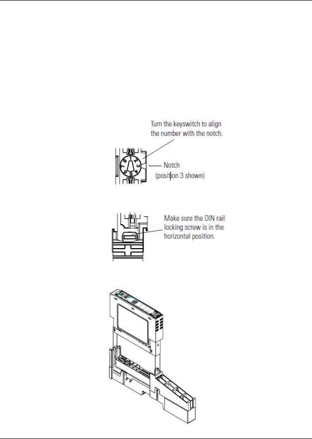
2.2Installing an I/O Module
Make sure that the mounting base is correctly keyed before installing the module into the mounting base. In addition, make sure the mounting base locking screw is positioned horizontal referenced to the base.
Warning: When you insert or remove the module while backplane power is on, an electrical arc can occur. This could cause an explosion in hazardous location installations.
Be sure that power is removed or the area is non-hazardous before proceeding.
1.Using a bladed screwdriver, rotate the key switch on the mounting base clockwise until the number required for the type of module being installed aligns with the notch in the base.
2.Make certain the DIN-rail locking screw is in the horizontal position. You cannot insert the module if the locking mechanism is unlocked.
3.Insert the module straight down into the mounting base and press to secure. The module locks into place.
Page 10 of 34 |
ProSoft Technology, Inc. |
|
February 18, 2015 |
Installing the Adapter
2.3Installing the Removable Terminal Block
A removable terminal block is supplied with the mounting base assembly. To remove, pull up on the RTB handle. This allows the base to be removed and replaced as necessary without removing any of the wiring. Follow the following instructions to reinsert the removable terminal block:
1.Insert the RTB end opposite the handle into the base unit. This end has a curved section that engages with the mounting base.
Warning: When you connect or disconnect the Removable Terminal Block (RTB) with the field side power applied, an electrical arc can occur. This could cause an explosion in hazardous location installations.
Be sure that power is removed or the area is non-hazardous before proceeding.
2.Rotate the terminal block into the mounting base until it locks itself in place.
3.If an I/O module is installed, snap the RTB handle into place on the module.
2.4Removing a Mounting Base
In order to remove a mounting base, you must remove any installed module, and remove the Removable Terminal Block (if wired).
1.Unlatch the RTB handle on the I/O module.
2.Pull on the RTB handle to remove the Removable Terminal Block.
Warning: When you connect or disconnect the Removable Terminal Block (RTB) with the field side power applied, an electrical arc can occur. This could cause an explosion in hazardous location installations.
Be sure that power is removed or the area is non-hazardous before proceeding.
3.Press in on the module lock on the top of the module and pull up on the I/O module to remove from the base.
ProSoft Technology, Inc. |
Page 11 of 34 |
February 18, 2015 |
|
 Loading...