


STUDIOLIVE 16.4.2 - V1.12
16 Channel Digital Recording and Performance Mixer
© P reS onus Audio Electro nic s, I nc.
All Rights Res erv ed.
StudioLive
™
16 . 4 . 2
16 Channel Digital Recording and Performance Mixer
Us er Man ual Ver sio n 1 .12

StudioLive
User’s Manual
Version 1.12

PreSonus Audio Electronics Inc. warrants this product to be free of defects in material and
workmanship for a period of one year from the date of original retail purchase. This warranty is
enforceable only by the original retail purchaser. To be protected by this warranty, the purchaser
must complete and return the enclosed warranty card within 14 days of purchase. During the
warranty period PreSonus shall, at its sole and absolute option, either repair or replace, free of
charge, any product that proves to be defective on inspection by PreSonus or its authorized
service representative. To obtain warranty service, the purchaser must rst call or write PreSonus
at the address and telephone number printed below to obtain a Return Authorization Number
and instructions of where to return the unit for service. All inquiries must be accompanied by a
description of the problem. All authorized returns must be sent to the PreSonus repair facility
postage prepaid, insured and properly packaged. PreSonus reserves the right to update any unit
returned for repair. PreSonus reserves the right to change or improve the design of the product
at any time without prior notice. This warranty does not cover claims for damage due to abuse,
neglect, alteration, or attempted repair by unauthorized personnel and is limited to failures arising
during normal use that are due to defects in material or workmanship in the product. Any implied
warranties, including implied warranties of merchantability and tness for a particular purpose,
are limited in duration to the length of this limited warranty. Some states do not allow limitations
on how long an implied warranty lasts, so the above limitation may not apply to you. In no event
will PreSonus be liable for incidental, consequential, or other damages resulting from the breach
of any express or implied warranty, including, among other things, damage to property, damage
based on inconvenience or on loss of use of the product, and, to the extent permitted by law,
damages for personal injury. Some states do not allow the exclusion of limitation of incidental or
consequential damages, so the above limitation or exclusion may not apply to you. This warranty
gives you specic legal rights, and you may also have other rights, which vary from state to state.
This warranty only applies to products sold and used in the United States of America. For warranty
information in all other countries please refer to your local distributor.
PreSonus Audio Electronics, Inc.
7257 Florida Blvd.
Baton Rouge, LA 70806
www.presonus.com
PreSonus Limited Warranty

To avoid damage to your StudioLive and your other audio equipment please review and adhere to
the following safety guidelines:
• Follow the safety guidelines in the manual.
• Do not block the ventilation openings.
• Do not drop your StudioLive.
• Do not install near a heat source (radiators, heat registers, amplier heat sinks, etc.).
• Do not expose your StudioLive to liquids. Do not place containers lled with liquids near your
StudioLive.
• Do not allow dust particles to collect in excess on your StudioLive. Keeping the unit covered
when not in use is highly recommended and will extend the life of your product.
• Protect the power cord from being walked on, wheeled over, or pinched. If your IEC cord
becomes damaged, purchase a new one.
• Unplug your StudioLive when not in use for long periods of time and during electrical storms,
hurricanes, tornadoes, and other extreme weather.
• Use only the attachments/accessories recommended or manufactured by PreSonus for your
StudioLive.
• All domestic PreSonus products should be serviced at the PreSonus factory in Baton Rouge,
Louisiana. If your StudioLive requires a repair contact techsupport@presonus.com to arrange
for a return authorization number. Customers outside the U.S. should contact their local
distributor. Your distributor’s contact information is available at www.presonus.com.
Safe Operation Guidelines

1 Overview
1.1 Introduction ................................................................................ 9
1.2 Features
..................................................................................... 10
1.3 What Is In the Box
..................................................................... 12
1.4 Getting Started: Mixing
............................................................... 13
2 Controls & Connections
2.1 The Patch Bay ........................................................................... 15
2.2 Hook-up Diagram: On Stage With the StudioLive
...................... 19
2.3 The Fat Channel
.......................................................................... 20
2.3.1 The Select Button ............................................................... 21
2.3.2 Dynamics & EQ ................................................................... 23
2.3.3 Panning & Stereo Link ........................................................ 32
2.3.4 Output Assignments ........................................................... 33
2.3.5 Copy, Save, Load ............................................................... 34
2.4 Metering
...................................................................................... 35
2.4.1 Metering Controls ............................................................... 36
2.5 Input Channel Strip
..................................................................... 37
2.5.1 Input Channel Controls ....................................................... 37
2.6 The Aux Bus
............................................................................... 39
2.6.1 Analog Aux Sends .............................................................. 39
2.6.2 Internal Effects-Send Controls ............................................ 41
2.7 Subgroups
.................................................................................. 42
2.8 Main Output Bus
......................................................................... 44
2.9 Master Section
............................................................................ 45
2.9.1 Aux Inputs A and B ............................................................. 46
2.9.2 Talkback System ................................................................. 47
2.9.3 2 Track In ............................................................................ 48
2.9.4 Solo Bus ............................................................................. 49
2.9.5 Monitor Bus ........................................................................ 50
Table of Contents

2.10 Digital Effects | Master Control ................................................ 52
2.10.1 The FX Menu ................................................................. 53
2.10.2 Creating & Recalling a Scene........................................ 55
2.10.3 Saving & Loading Channel Presets ............................... 58
2.10.4 The System Menu ......................................................... 59
3 Recording
3.1 System Requirements ................................................................ 62
3.2 Getting Started: Recording ........................................................ 63
3.2.1 Installation on Microsoft Windows .................................. 63
3.2.2 Installation on Mac OS X ................................................ 64
3.3 Using your StudioLive as an Audio Interface ............................. 65
3.3.1 FireWire Sends & Returns ............................................... 66
3.3.2 Using Plug-in Effects as Inserts ...................................... 67
3.3.3 Universal Control ............................................................ 69
3.3.4 Advanced WDM Features (PC Only) ............................... 74
3.3.5 Conguring Your StudioLive for Core Audio (Mac Only) . 75
3.3.6 Enabling and Using Lockout Mode ................................. 76
3.4 Hook-up Diagram: In the Studio with the StudioLive ................. 77
4 Multiple Mixers
4.1 Getting Started .............................................................................. 78
4.1.1 Conguring Multiple Units ............................................. 78
4.1.2 Aux Mixing With Cascaded Mixers ................................. 79
4.1.3 Internal Effects Buses ..................................................... 80
4.1.4 Subgroups: To Merge or Not To Merge ........................... 80
4.1.7 Scene Store and Recall .................................................. 81
4.1.6 Copy and Load ............................................................... 81
4.17 Universal Control and Multiple Mixers ............................. 81
4.2 Local Versus Merged Buses and Inputs ..................................... 82
Table of Contents

5 Tutorials
5.1 Studio One Artist Quick Start .................................................... 83
5.1.1 Installation and Authorization ........................................ 83
5.1.2 Enabling the Audio Driver .............................................. 86
5.1.3 Conguring Your MIDI Devices ....................................... 87
5.1.4 Conguring Audio I/O ..................................................... 90
5.1.5 Creating a Song .............................................................. 92
5.2 Microphones
............................................................................. 96
5.2.1 Condenser ..................................................................... 96
5.2.2 Dynamic ......................................................................... 96
5.2.3 USB and Other Types ..................................................... 97
5.2.4 Microphone Placement ................................................... 97
5.3 A Brief Tutorial on Dynamics Processing ................................... 100
5.3.1 Common Questions Regarding Dynamics Processing ... 100
5.3.2 Types of Dynamics Processing ....................................... 102
5.3.3 Vocabulary of Dynamics Processors............................... 104
5.3.4 General Compression Setting Suggestions .................... 107
5.4 Equalizers .................................................................................. 110
5.4.1 What is an EQ? ............................................................... 110
5.4.2 How to Find the Best and Leave the Rest ...................... 113
5.4.3 To Boost or Not to Boost ................................................ 114
5.4.4 General EQ Setting Suggestions .................................... 116
5.5 Subgroup Mixing ....................................................................... 119
5.5.1 Instrument Groups .......................................................... 119
5.5.2 Effects Groups ................................................................ 121
5.6 Aux Bus Mixing .......................................................................... 122
5.6.1 Monitor Mixing ................................................................ 122
5.6.2 Effects Processing .......................................................... 123
5.7 Digital Multi-Effects ................................................................... 125
5.7.1 Reverb ............................................................................ 125
5.7.2 Delay ............................................................................... 126
Table of Contents

5.8 Level-Setting Procedure ............................................................ 127
5.9 The Solo Bus ............................................................................. 128
5.9.1 Using the Solo Bus for Monitoring .................................. 129
5.9.2 Destructive Soloing ......................................................... 130
5.9.3 Using Solo In Place (SIP) to Set Up a Mix ...................... 130
6 Technical information
6.1 Troubleshooting ......................................................................... 131
6.2 Specications ............................................................................ 134
6.3 Channel Strip Library ................................................................. 137
6.4 Effects Library ............................................................................ 138
6.5 Rack Ear Installation Instructions .............................................. 139
6.6 Session Data Recall Sheet ......................................................... 140
Table of Contents
Overview
Con trol s &
Con nect ions
Rec ordi ng
9
Tutori als
Technic al
Inf orma tion
Mul tipl e
Mixe rs
Thank you for purchasing the PreSonus StudioLive™ 16.4.2. PreSonus Audio Electronics has
designed the StudioLive™ utilizing high-grade components to ensure optimum performance that
will last a lifetime. Loaded with 16 high-headroom, XMAX microphone preampliers; a built-in 32x18
FireWire recording and playback engine; Fat Channel processing with 4-band EQs, compressors,
limiters, and expander/gates; DSP effects; 6 aux buses; 4 subgroups; extensive LED metering;
mix er save/recall; channel-strip save/recall/copy/paste; talkback; and more, StudioLive breaks new
boundaries for music performance and production. All you need is a computer with a FireWire
connection, a few microphones and cables, speakers, and your instruments, and you are ready to
record in the studio or in front of a live audience!
We encourage you to contact us at (225) 216-7887 with any questions or comments you may have
regarding your PreSonus StudioLive. PreSonus Audio Electronics is committed to constant product
improvement, and we value your suggestions highly. We believe the best way to achieve our goal
of constant product improvement is by listening to the real experts, our valued customers. We
appreciate the support you have shown us through the purchase of this product.
We suggest that you use this manual to familiarize yourself with the features, applications, and
correct connection procedures for your StudioLive before trying to connect it to your computer.
This will help you avoid problems during installation and setup.
1 Overview
1.1 Introduction

10
11
Thank you, once again, for buying our product—we are condent that you will enjoy your StudioLive!
The StudioLive™ performance and recording digital mixer is a fully-loaded professional digital
mix er combined with a complete 32x18 FireWire recording system. Racks of processing effects
including compressor, limiter, gate, four-band parametric EQ, reverb and delay are available on every
channel, subgroup, aux, and main mix delivering total control in a compact rugged steel chassis.
StudioLive™ includes CAPTURE™, a fully integrated live recording software by PreSonus, allowing
you to record every performance and rehearsal with a few clicks of your mouse.
Intuitive, exible and powerful, StudioLive revolutionizes music production opening endless creative
possibilities.
Summary of features
• 24-bit/48 kHz sampling rate
• 16 Class A XMAX microphone preampliers
• 16 line-level inputs
• 6 auxiliary buses
• 4 subgroups
• High-denition analog to digital converters (118 dB dynamic range)
• Unlimited-headroom, 32-bit oating-point, digital mixing and effects processing
• 32x18 FireWire digital recording interface with two FireWire 400 (IEEE 1394) ports
• Scene automation with load/save/recall of all settings
• Fat Channel with:
• High-pass lter
• Compressor
• Limiter
• Expander/Gate
• 4-band semi-parametric EQ
• Pan
• Load/save
• 2 master DSP effects (reverb and delay with Load and Save)
• 100 mm long-throw faders
• Military-grade quick-touch buttons
• Fast-acting LED meters
• Talkback communication system
• Compact, 19” rack-mountable, rugged steel chassis
• PreSonus Capture™ multitrack-recording software
• Compatible with Logic, Cubase, Nuendo, Sonar, Digital Performer and others
• PC and Mac compatible
1 Overview
1.2 Features

Overview
Con trol s &
Con nect ions
Rec ordi ng
11
Tutori als
Technic al
Inf orma tion
Mul tipl e
Mixe rs
1 Overview
1.2 Features
Included with your StudioLive is CAPTURE; a digital audio multi-tracking application designed to
make recording quick and easy to set-up and operate. Perfect for live recording or mixing your
audio real-time to a stereo audio le, CAPTURE software was designed to interface with StudioLive
16.4.2 perfectly to allow instant setup and recording of performances.
In addition to recording the 16 channels of the StudioLive 16.4.2, CAPTURE also allows you to
record a single stereo track from the StudioLive’s Main Output, one pair of Subgroup Outputs or a
pair of Aux Sends; giving you the option to record your Main Mix or create a separate recording mix.
And you can arm all 18 tracks to record with the click of a single button. Please consult the User
Manual that came with your StudioLive for complete instructions on using CAPTURE.
Summary of Capture features
• 18x18 Multi-track recording application
• Record with two mouse clicks
• Essential Editing Suite (copy, cut, paste, splice, resize)
• Peak LED-style meter bridge with clip indicators
• Marker placement and recall
• Export between marker
• Record stereo mix of StudioLive Mixer
• Import/Export individual .wav, .aiff, .mp3, or OpenTL
All PreSonus audio interfaces now include PreSonus Studio One Artist recording software, which
comes with over 4 GB of plug-ins, loops, and samples, giving you everything you need for music
recording and production. A Quick Start Guide to using Studio One Artist is located in Section 5.1
of this manual. You will nd a complete User‘s Manual on the Studio One Artist Installation DVD.
Summary of Studio One Artist features
• Unlimited track count, inserts and sends
• 20 high-quality native plug-ins: Amp Modeling (Ampire), Delay (Beat Delay), Distortions
(Redlight Dist), Dynamic Processing (Channel Strip, Compressor, Limiter, Tricomp), Equalizer
(Channel Strip, Pro EQ), Modulation (Autolter, Chorus, Flange, Phaser, X-Trem), Reverb
(MixVerb, Room Reverb), Utility (Binaural Pan, Mixtool, Phase Meter, Spectrum Meter, Tuner)
• Over 4 GB of loops, samples, and instruments, featuring: Presence (Virtual Sample Player),
Impact (Virtual Drum Machine), SampleOne (Virtual Sampler), Mojito (Virtual Analog-Modeled
Subtractive Synthesizer)
• Innovative and intuitive MIDI mapping
• Powerful drag-and-drop functionality for faster workow
• Mac OS X and Windows compatible
12
13
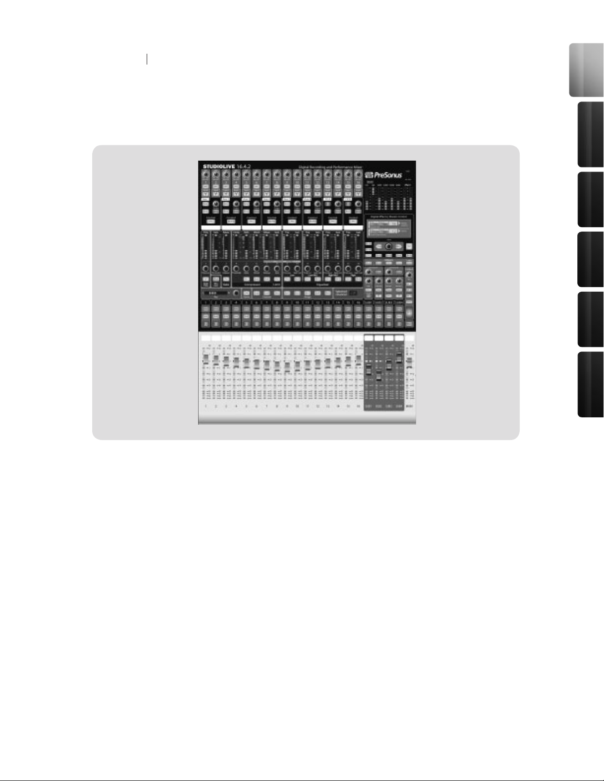
In addition to this manual, your StudioLive package contains the following:
1 Overview
1.3 What is in the Box
• PreSonus StudioLive digital recording
and performance mixer
• 6’ 6-pin-to-6-pin FireWire 400 cable
• IEC power cord
• Software installation DVD containing:
• PreSonus StudioLive drivers
• PreSonus Capture
• PreSonus Capture Demo Session
• Studio One Artist Installation DVD
• PreSonus Capture Reference Manual
• Rack Ear Installation Kit

Overview
Con trol s &
Con nect ions
Rec ordi ng
13
Tutori als
Technic al
Inf orma tion
Mul tipl e
Mixe rs
Before you begin, there are a few general rules of thumb that we recommend you follow:
• Always turn the Main fader and both the Monitor and Phones knobs in the Monitor section
down before making connections. Before plugging or unplugging a microphone while other
channels are active, mute the channel to which you are connecting.
• Your faders should be set on or near the “U” mark whenever possible. The “U” indicates
unity gain, meaning the signal is neither boosted nor attenuated. If the main output of you
Studiolive is too high or too low when your faders are at or near unity, you can use the output
level knob on the rear panel of your StudioLive to adjust the level up or down until you have
achieved your optimal volume.
• Do not allow your inputs to clip. Watch the level meters; when the LEDs near the Clip mark,
the top LED will illuminate, indicating that the analog-to-digital converters are in danger of
being overdriven. Overdriving the converters will cause digital distortion, which sounds terri-
ble. The XMAX preamps in your StudioLive provide plenty of headroom; take advantage of it.
• Your P.A. and studio equipment should be powered on in the following order:
1. Sound sources (keyboards, direct boxes, microphones, etc.) connected to the
StudioLive inputs)
2. StudioLive
3. Computer (if applicable)
4. Power ampliers or powered monitors
When it’s time to power down, your system should be turned off in the reverse order.
Now that you know what not to do, let’s get some audio going!
1. Grab a microphone and a mic cable and plug it into the StudioLive’s Channel 1 mic input.
2. Connect the Main Outs (TRS or XLR) of your Studio Live to your power amplier or powered
monitors.
3. If you’re using passive speakers, connect them to your power amplier using speaker cable.
4. Bring down all the faders on your StudioLive.
5. Plug your StudioLive into a power outlet and turn it on.
6. If your microphone requires phantom
power, engage the 48V button on
Channel 1 of your StudioLive.
7. Turn on your amplier or powered monitors.
1 Overview
1.4 Getting Started: Mixing
14 15
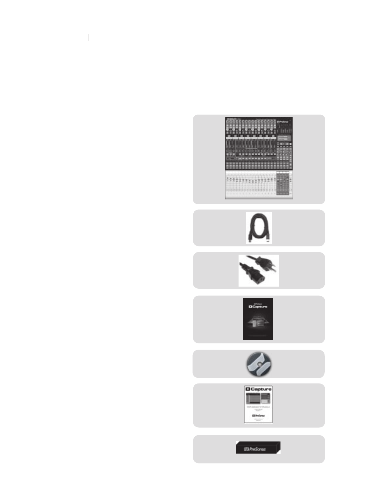
8. Press the Input button in the Meter
section.
9. While speaking or singing into your microphone, turn the trim knob on Channel 1 until the
signal reaches the desired lev el, but don’t raise it too much or the input will clip. Watch the
level meter.
10. Press the Select button on Channel 1
and bring the fader to unity gain.
11. Press the Main button in the Assign
section of the Fat Channel so that it is
illuminated. This routes the channel to
the main output bus.
12. Bring up the Main fader until you can comfortably listen to your microphone through your
speakers.
13. With Channel 1 selected, you can use the Fat Channel to add dynamics processing and EQ.
For more detailed level-setting procedures and techniques, refer to sections 5.8 and 5.9.3
1 Overview
1.4 Getting Started: Mixing
Control s &
Connect ions
Rec ordi ng
Tutori als
Technic al
Inf orma tion
Mul tipl e
Mixe rs
Ove rvie w
• Microphone Inputs. Your StudioLive is equipped with 16 custom-designed PreSonus
XMAX microphone preampliers for use with all types of microphones (including dynamics,
condensers, and ribbons). The award winning PreSonus preamplier has a Class A input
buffer followed by a dual-servo gain stage. This arrangement results in ultra-low noise and
wide gain control, allowing you to boost signals without increasing unwanted background
noise.
• 48-Volt Phantom Power. The StudioLive has 48V phantom power available for each
channel individually via buttons on the top panel.
• XLR Connector Wiring for Phantom Power:
• Pin 1 = GND
• Pin 2 = +48V
• Pin 3 = +48V
• 22 dBu Headroom. The StudioLive microphone preamplier has +22 dBu headroom.
This gives you wide dynamic range and excellent transient-response characteristics.
• Line-Level Input. Each channel of the StudioLive has a 1/4-inch, balanced TRS connection
for line-level input. When these inputs are engaged, the microphone-preamp circuit is
bypassed.
Please Note: As with any mixer, plugging in a microphone or a line-level input device as well
as turning phantom power on or off will create a momentary spike in the audio output of your
StudioLive. Because of this, it is highly recommended that you mute or turn down the trim of any
channel before changing any connections or turning phantom power on or off. This simple step
will add years to life of your audio equipment.
• Insert. Each channel of the StudioLive has a direct-insert point. These unbalanced 1/4”
connectors can be used to connect external processors such as compressors, EQs, de-
essers, and lters with your StudioLive’s preamps and line inputs. The insert’s send is
after the channel’s gain control but before the digital bus. The return goes straight to the
digital bus. In other words, if you insert a de-esser on your vocalist’s channel, you will be
sending an unprocessed, amplied signal to the de-esser; the processed signal returned to
the StudioLive will then be routed to the digital bus, where it can be sent through the Fat
Channel, Aux and FX buses, etc.
2 Controls & Connections
2.1 The Patch Bay
16
17
• Insert connector wiring:
• Tip = send (output to inserted device)
• Ring = return (input from inserted device)
• Sleeve = common ground
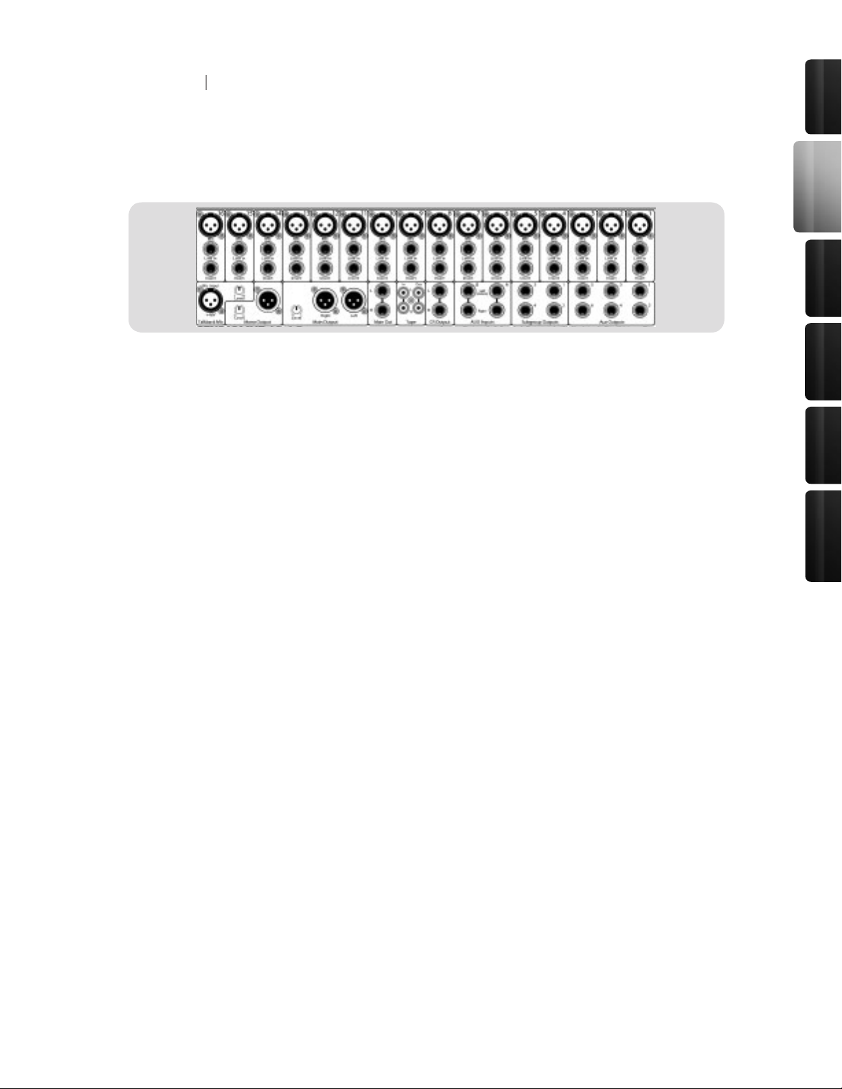
• Aux Inputs. The StudioLive is equipped with two auxiliary inputs (effects returns). In Section
5.5.2, we discuss using an aux bus to send several channels to an external effects processor;
the Aux inputs can be used to return the processed signal to the mixer. Each input is balanced
stereo. The Left input is normalled to the right. If you are returning a mono signal to the mix,
simply connect it to the Left input; the signal will be routed to both sides of the stereo mix.
• Subgroup Outputs. These are balanced mono outputs for each subgroup.
• Aux Outputs. The StudioLive is equipped with six auxiliary outputs. In Section 5.5, we dis-
cuss in detail how to create aux mixes for monitoring and effects processing. Aux mixes are
routed to these outputs.
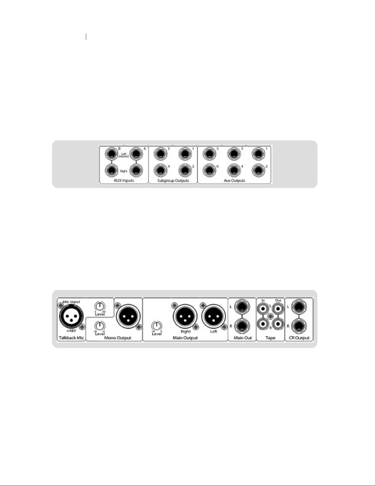
• Talkback Mic Input. The StudioLive does not have an onboard talkback mic; an external
mic must be used. Phantom power is always enabled on this microphone preamp, so either
a dynamic or a condenser microphone can be used. This is the same high-quality XMAX
preamp that is featured on Channels 1-16 and can be used as an extra input when using the
StudioLive as an audio interface. See Section 3.3.1 for more details.
• Talkback Mic Level. This is the gain control for your talkback microphone.
• Mono Output. This balanced output carries a mono, summed version of the stereo signal
from the main bus.
2 Controls & Connections
2.1 The Patch Bay
17
Control s &
Connect ions
Rec ordi ng
Tutori als
Technic al
Inf orma tion
Mul tipl e
Mixe rs
Ove rvie w
• Mono Output Level. This knob controls the maximum level of the Mono Output signal. The
signal can be attenuated to -40 dB and boosted up to +10 dB.
• Main Output. The StudioLive features both XLR and TRS main outputs. These outputs are
parallel to each other and to the mono output.
• Main Output Level. This knob controls the maximum output level of both the XLR and TRS
main outputs. The signal can be attenuated to -40 dB and boosted up to +10 dB.
• Tape In/Out. The StudioLive is equipped with stereo RCA (coaxial) inputs and outputs that
can be used to connect a tape deck, CD player, or other consumer device. The tape-input
level is controlled by the 2Track In knob on the top panel. The main bus is routed post-fader
to the tape output.
• CR Output. These are the balanced control-room outputs. The level is controlled by the
Monitor knob in the Monitor section on the top panel.
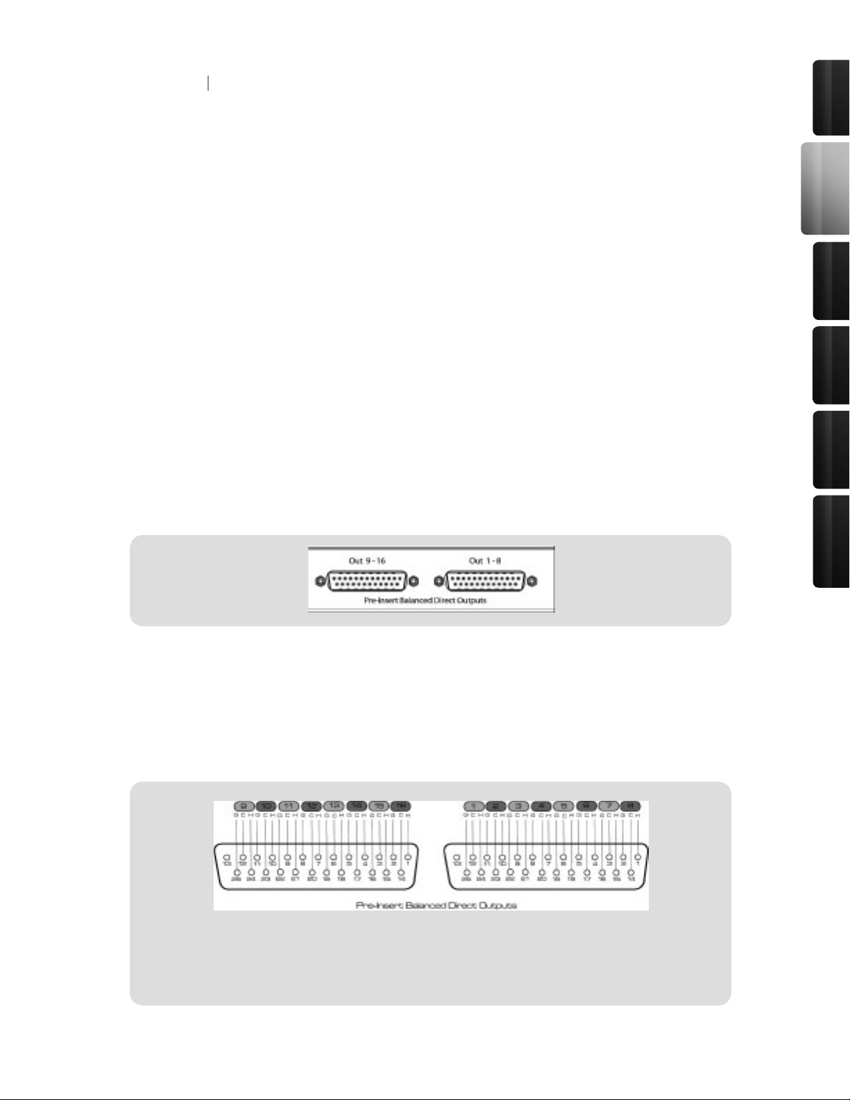
• Pre-Insert Balanced Direct Outputs. These are the balanced, direct analog outputs for the
16 channels. The DB25 connectors divide the channels into two groups of eight. Balanced
DB25 fan-out snakes can be obtained in various congurations at most recording and livesound retailers. Common fan-outs are DB25 to (8) XLRM and DB25 to (8) TRS. These outputs
are post gain, pre-insert, and pre-A/D converter. Only the microphone preamps and line level
inputs are available through the direct outputs. The rewire returns (See Section 3.3.1 for
more information) cannot be patched to the direct outputs.
2 Controls & Connections
2.1 The Patch Bay
DB25 Pinout
H = Hot
C = Cold
G = Ground
18
19
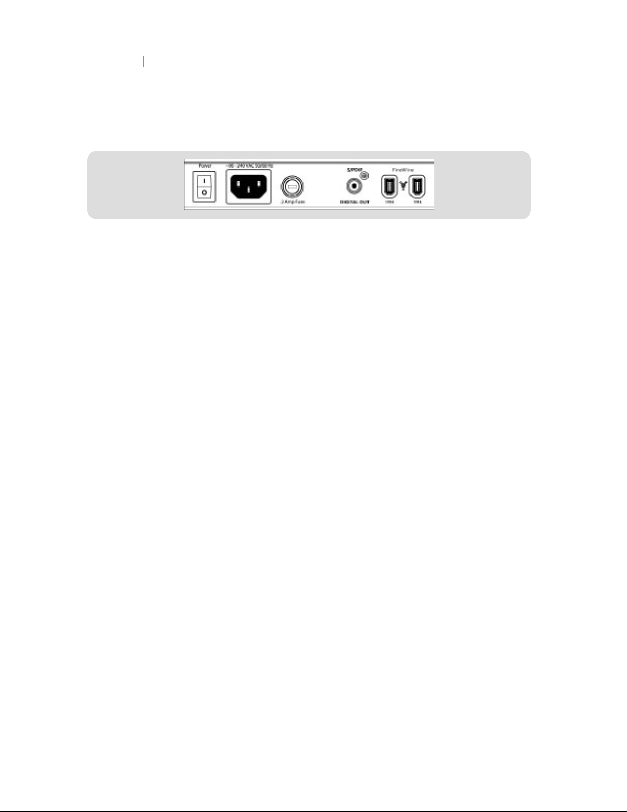
• FireWire Ports. There are two standard 6-pin FireWire 400 ports on the back of the StudioLive.
Either port can be used to connect your StudioLive to a FireWire port on your computer. If your
computer has a 4-pin connector (commonly found on laptops), you will need to purchase a
4-to-6-pin adaptor or cable. These adaptors and cables can be found at your local computer
supply store. Use the second FireWire port to connect additional FireWire devices (such as
external hard drives) to your computer or to daisy chain additional StudioLive mixers. You
can connect two StudioLive mixers to a computer for recording, or you can daisy-chain up to
eight StudioLive mixers to creates a standalone large-format mixing console.
• 2 Amp Fuse. This is the StudioLive’s fuse housing. Your StudioLive uses a 5 mm x 20 mm,
250 VAC, fast-acting fuse.
• S/PDIF Output. By default, the S/PDIF output receives the same signal as the main outputs,
so no activation is necessary. However, any of buses that can be routed to the auxiliary
FireWire returns, can be routed to the S/PDIF output, either through the System menu in
the Digital Effects | Master Control section or in the StudioLive Control Panel (see Sections
2.10.4 and 3.3.3 for more information). Because the StudioLive cannot be synced externally,
you will need to use it as the master clock and set your S/PDIF-equipped device to receive
word clock externally via S/PDIF. Please consult the documentation for your external digital
device for instructions.
• Power-Adapter Input. This is where you plug in the provided IEC power cable.
• Power Switch. Push the top part of the switch ( | ) to turn on your StudioLive. Push the
bottom part of the switch ( O ) to turn it off.
2 Controls & Connections
2.1 The Patch Bay
19
Control s &
Connect ions
Rec ordi ng
Tutori als
Technic al
Inf orma tion
Mul tipl e
Mixe rs
Ove rvie w
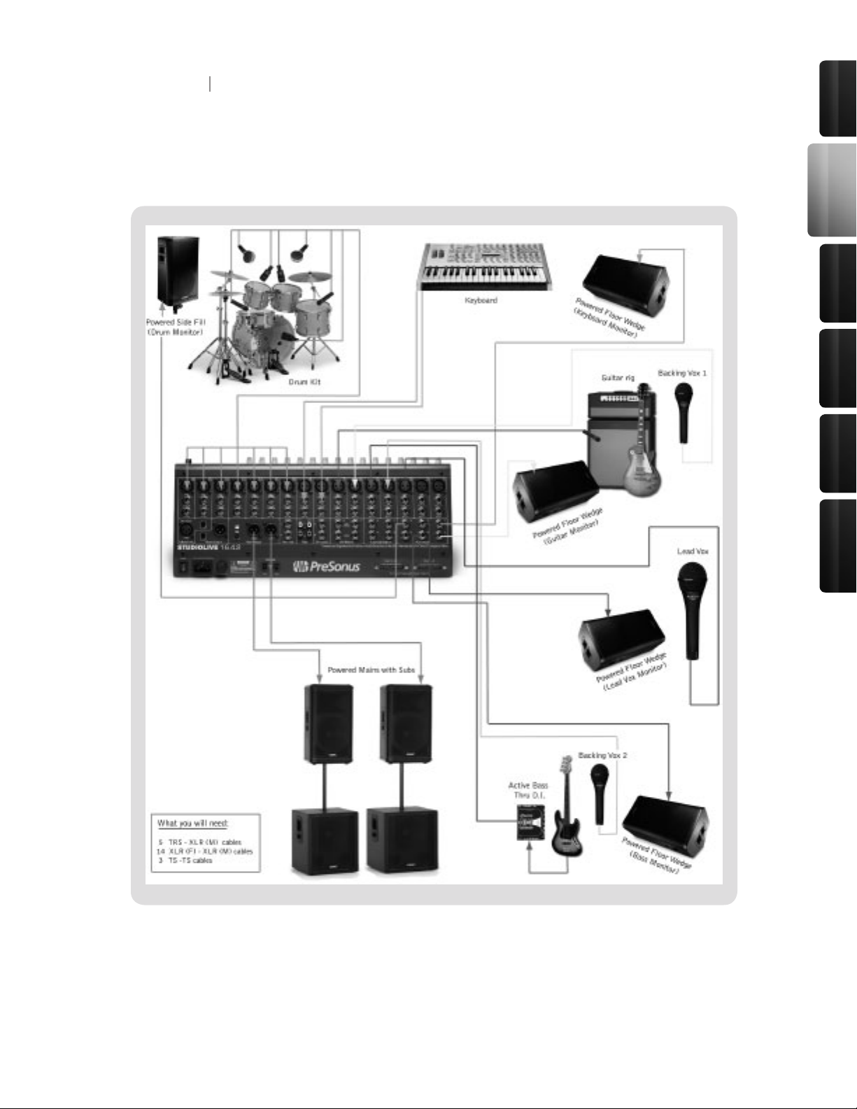
2 Controls & Connections
2.2 Hookup Diagram:
On Stage with the StudioLive
20
21
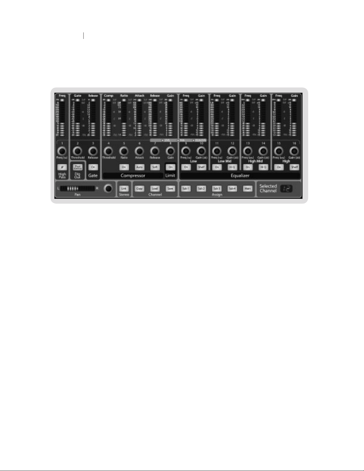
2 Controls & Connections
2.3 The Fat Channel
The heart of the StudioLive is the revolutionary Fat Channel. The Fat Channel makes dynamics,
routing, and panning for every input and output on the StudioLive available at the touch of a Select
button. The 16 multipurpose knobs and meters located in the Fat Channel control nearly every
adjustment you will need to make on your StudioLive. From the Fat Channel, you can:
• Add dynamics processing and EQ to every input and output
• Create sends and effects mixes for all 6 analog aux sends and both internal effects buses
• Assign subgroup and main routing
• Meter inputs, post-dynamic outputs, and gain reduction for all 16 channels
• Meter aux send outputs
• Copy, save, and load mix scenes
• Recall your fader position for stored mixes
21
Control s &
Connect ions
Rec ordi ng
Tutori als
Technic al
Inf orma tion
Mul tipl e
Mixe rs
Ove rvie w
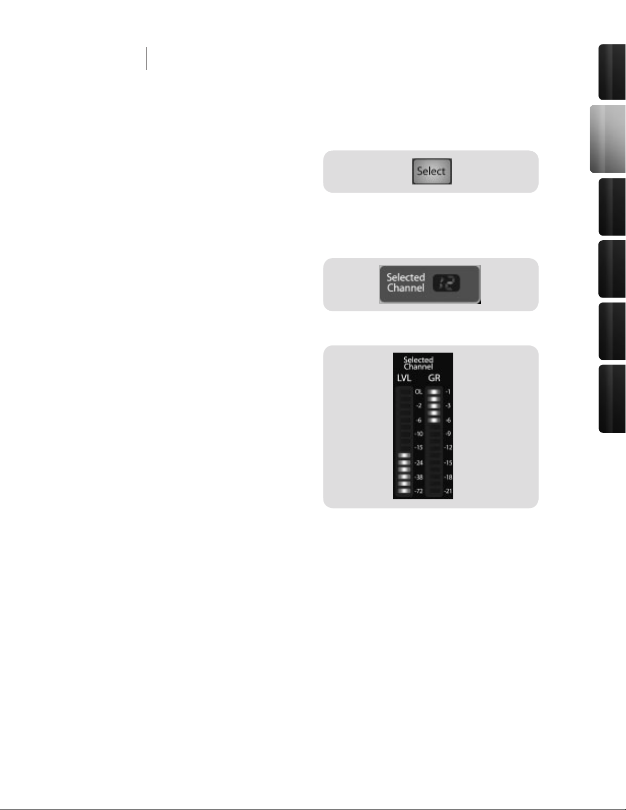
All around the StudioLive, you will see Select
buttons. There is a Select button on each of
the 16 inputs, each of the 6 analog aux sends,
both of the internal effects buses, each of the
4 subgroups, the two auxiliary inputs, and last, but certainly not least, the main output bus. Each
of these buttons serves exactly the same purpose: to access the Fat Channel parameters for its
channel or bus.
In the lower right corner of the Fat Channel, you
will nd an LED read out. The currently selected
channel will always be displayed here. (Numbers
1-16 indicate one of the 16 inputs channels is
selected, S1-S4 indicates Subgroups 1-4, MA
indicates the Main bus, A1-A6 indicates Aux 1-6, A7 and A8 indicate EFX A and EFX B, and F1 and
F2 indicate Aux inputs A and B.)
In addition, two meters—part of a set of seven
meters located in the top right section of the
mixer—are dedicated to displaying information
about the currently selected channel. The meter
on the far left of this section, displays the prefader input level for the selected channel. The
meter to the right of it displays the gain reduction
for the selected channel. It is important to
mention that these meters are only active when
one of the 16 input channels or an aux bus is
selected.
It should be noted that while the Noise Gate, Compressor, EQ, and Limiter are available on every
input and bus, the phase reverse and hi-pass lter are only available on the 16 inputs. In addition,
other inputs and buses without Select buttons are available to route to the auxiliary FireWire returns
(see section 3.3.1 for more details).
2 Controls & Connections
2.3 The Fat Channel
2.3.1 The Select Button
22
23
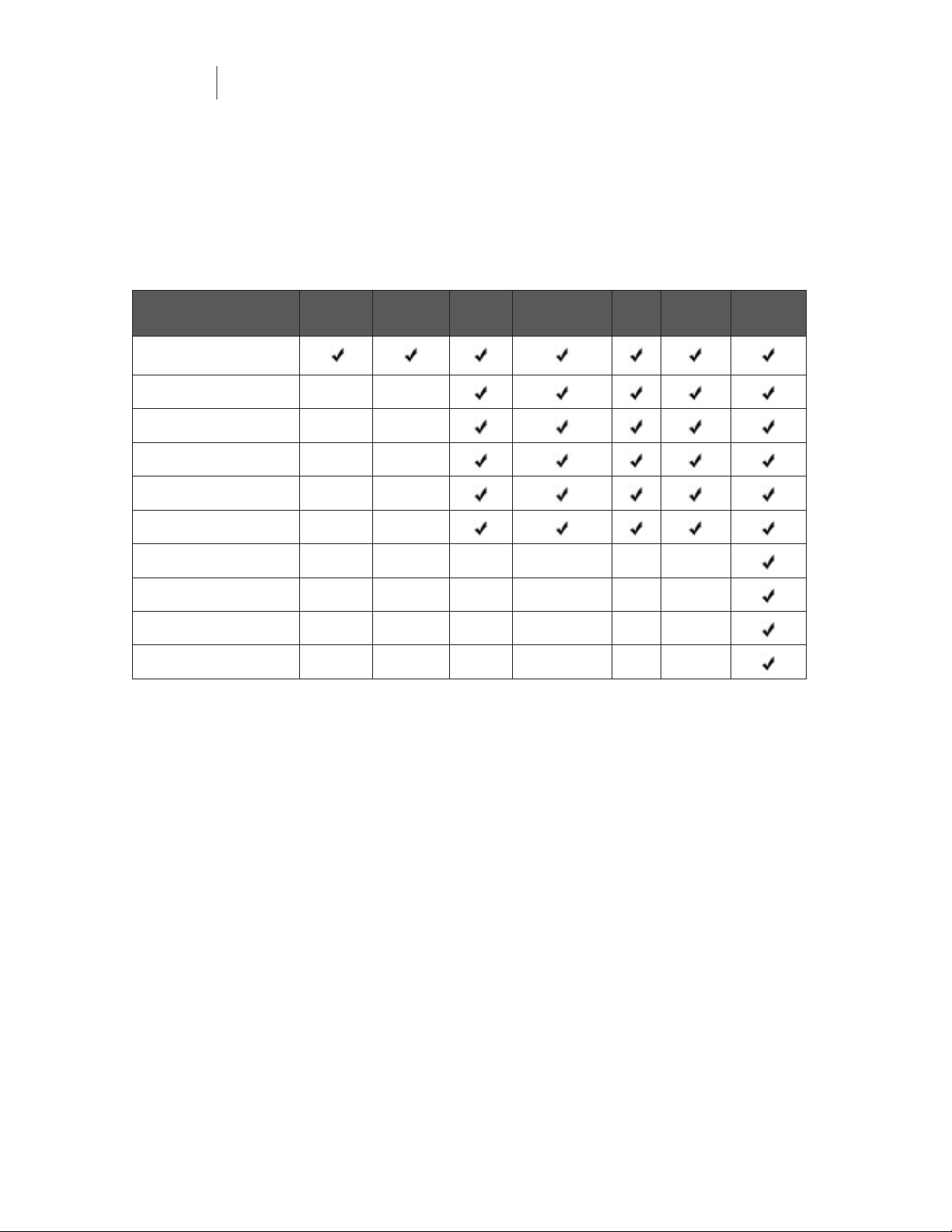
The following table provides a quick guide to the processing that is available for each bus in the
StudioLive:
Bus Phase
Reverse
Hi-Pass
Filter
Noise
Gate
Compressor EQ Limiter FireWire
send
Inputs (Ch 1-16)
Subgroups
Main Out L/R
Aux Sends 1-6
Internal FX Sends 1-2
External FX Returns 1-2
Tape Input
Talkback Mic
Solo Bus
Monitor Bus
2 Controls & Connections
2.3 The Fat Channel
2.3.1 The Select Button
23
Control s &
Connect ions
Rec ordi ng
Tutori als
Technic al
Inf orma tion
Mul tipl e
Mixe rs
Ove rvie w
2 Controls & Connections
2.3 The Fat Channel
2.3.2 Dynamics Processing and EQ
The main function of the Fat Channel is to provide dynamics processing and ltering for every input
and output on your StudioLive. The rotary encoders work in conjunction with the meters directly
above them to adjust the dynamics processing and EQ. The Fat Channel’s processing section
consists of ve parts: Hi Pass lter, Noise Gate, Compressor, Limiter, and semi-parametric EQ.
Each can be turned on or off and controlled separately. The signal ows as follows:
Phase Reverse button
Reverses the Phase of the Selected Channel.
Push this button to invert the phase of the selected
channel’s signal (that is, to alter the phase by 180°). The
button will illuminate, indicating that the phase reverse is
active. The Phase Reverse button can be used to correct
audio signals that are out of phase and cancelling each
other out.
Phase reverse is only available on the 16 channels of the
input bus.
High Pass filter
Engages the High Pass Filter.
The High Pass lter section consists of an encoder and a
meter. You will notice that the there is a frequency range
to the left of the meter. The high-pass lter’s threshold
can be set from 24 Hz to 1 kHz. When the meter is set to
its lowest point, the lter is off.
Remember, that all frequencies below a high-pass lter’s
threshold are attenuated. See section 5.3.1 for more
details.
The high-pass lter is only available on the 16 channels
of the input bus.
Gate On/Off button
Turns the Gate On and Off for the Selected Channel.
This button engages and disengages the gate for the
selected channel. It will illuminate to indicate that the
gate has been enabled.
The gate is available for all input and output buses.
24
25
2 Controls & Connections
2.3 The Fat Channel
2.3.2 Dynamics Processing and EQ
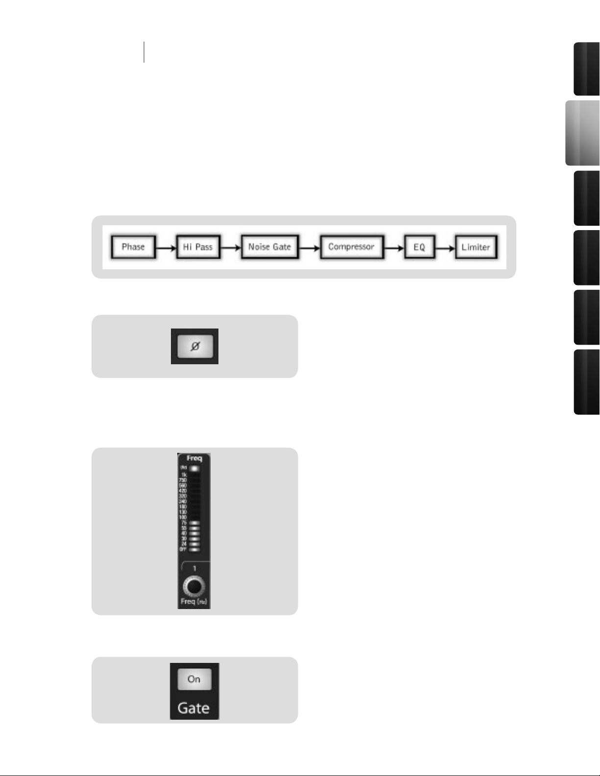
Gate Threshold
Sets and Displays the Threshold of the Gate for the
Selected Channel.
This encoder sets, and the meter displays, the gate
thresh old for the selected channel. The threshold determines the level at which the gate will open. Essentially, all
signals above the threshold setting are passed through
unaffected. - You can set the threshold from 0 to -84 dB.
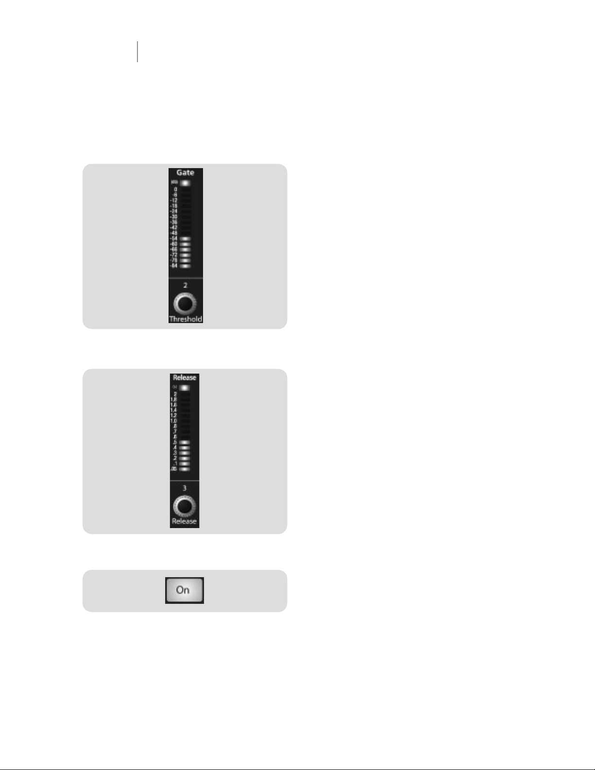
Gate Release
Sets and Displays the Rate the Gate Closes on the
Selected Channel.
This encoder sets, and the meter displays, the rate at
which the gate for the selected channel closes. The rate
can be set from 2 to 0.05 seconds.
Remember, gate-release times should typically be set so
that the natural decay of the instrument or vocal being
gated is not affected. Shorter release times help to clean
up the noise in a signal but may cause “chattering” in
percussive instruments. Longer release times usually
eliminate “chattering” and should be set by listening
carefully for the most natural release of the signal.
Compressor On/Off button
Turns the Compressor On and Off for the Selected
Channel or Output Bus.
This button engages or disengages the compressor for
the selected channel or output bus. It will illuminate to
indicate that the compressor has been enabled.
The compressor is available for all input and output
buses.
25
Control s &
Connect ions
Rec ordi ng
Tutori als
Technic al
Inf orma tion
Mul tipl e
Mixe rs
Ove rvie w
2 Controls & Connections
2.3 The Fat Channel
2.3.2 Dynamics Processing and EQ
Soft Knee/Hard Knee Toggle
Button
Engages Soft-Knee Compression.
In normal operating mode, the compressor is set for
hard-knee compression, meaning that the gain reduction
applied to the signal occurs as soon as the signal exceeds
the level set by the threshold. When the Soft Knee button
is engaged, the onset of gain reduction occurs gradually
after the signal has exceeded the threshold.
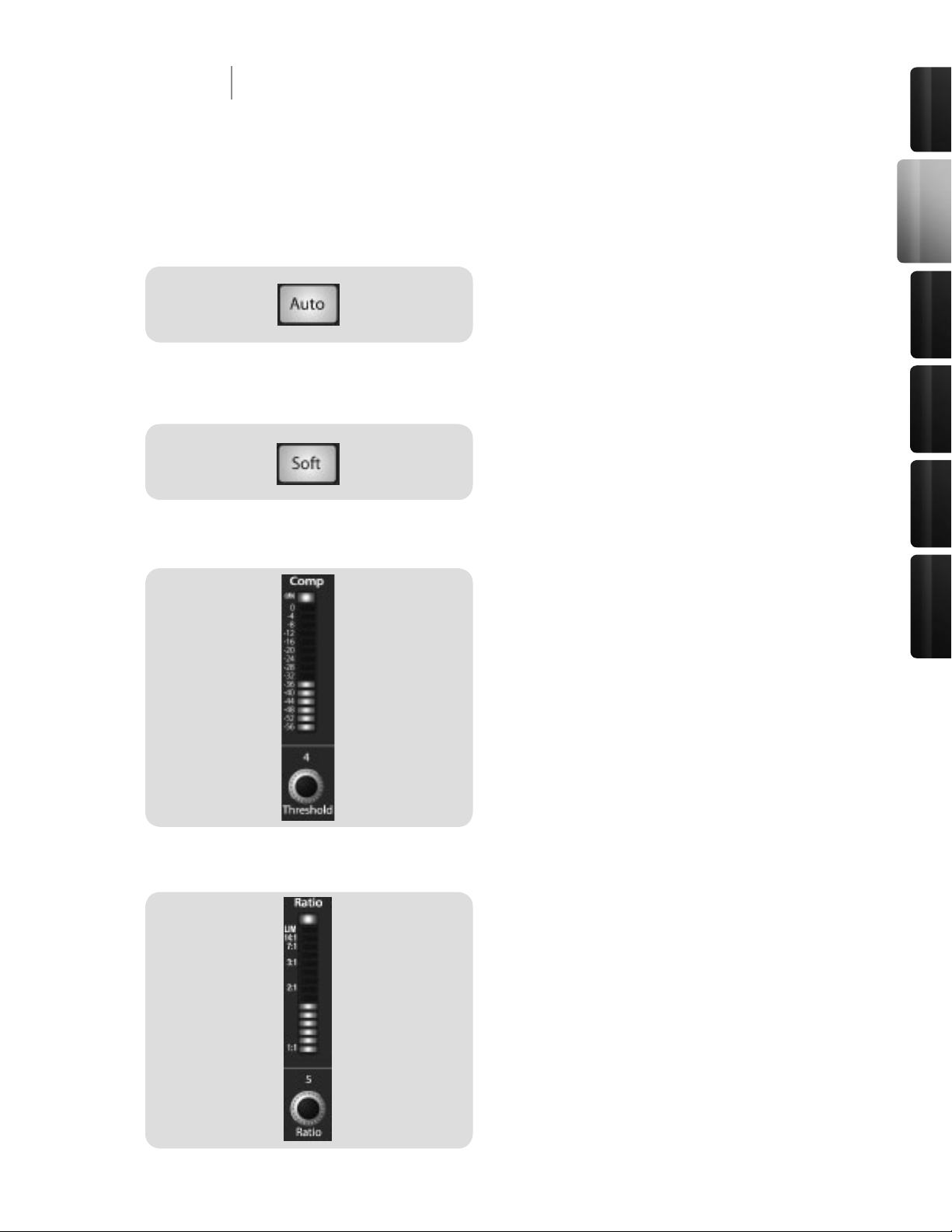
Compressor Threshold
Sets and Displays the Threshold of the Compressor
for the Selected Channel or Ouput Bus.
This encoder sets, and the meter displays, the threshold
of the compressor for the selected channel or output bus.
When the signal’s amplitude (level) exceeds the threshold
setting, the compressor is engaged. Turning the knob
counterclockwise lowers the threshold, so compression
begins at a lower amplitude. The threshold can be set
from -56 to 0 dB.
Compression Ratio
Sets and Displays the Compression Ratio Setting for
the Selected Input Channel or Output Bus.
This encoder sets, and the meter displays, the com-
pression ratio (or slope) for the selected channel or
output bus. The ratio sets the compression slope, which
is a function of the output level versus the input level. For
example, if you have the ratio set to 2:1, any signal levels
above the threshold setting will be compressed at a ratio
of 2:1. This means that for every 2 dB of level increase
above the threshold, the compressor’s output will only
increase 1 dB. The ratio can be set from 1:1 to 14:1.
Turns the Auto Button On
Enables Automatic Attack and Release Mode.
When Auto mode is active, the Attack and Release
controls become inoperative, and a preprogrammed
attack and release curve is used. In this mode, the attack
is set to 10 ms, and the release is set to 150 ms. All other
compressor parameters can still be adjusted manually.
26
27
2 Controls & Connections
2.3 The Fat Channel
2.3.2 Dynamics Processing and EQ
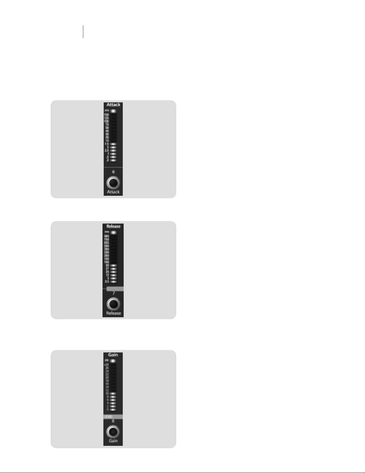
Compressor Attack
Sets and Displays the Compressor Attack Setting for
the Selected Input Channel or Output Bus.
This encoder sets, and the meter displays, the
compressor’s attack setting for the selected channel
or output bus. Attack sets the speed at which the
compressor acts on the input signal. A slow attack
time (fully clockwise) allows the beginning nonharmonic
component of a signal (commonly referred to as the initial
transient) to pass through, uncompressed, whereas a fast
attack time (fully counterclockwise) triggers compression
immediately when a signal excedes the threshold. You
can set the attack from 0.2 to 150 milliseconds.
Compressor Release
Sets and Displays the Compressor Release Setting
for the Selected Input Channel or Output Bus.
This encoder sets, and the meter displays, the release
setting of the compressor for the selected channel
or output bus. Release sets the length of time the
compressor takes to return the gain reduction back
to zero (no gain reduction) after crossing below the
compression threshold. Release can be set from 40 to
1000 milliseconds.
Remember, very short release times can produce a
choppy or “jittery” sound, especially when compressing
instruments that have a lot of low-frequency components,
such as bass guitar. Very long release times can result in
an overcompressed, or “squashed,” sound. All ranges
of release can be useful, however, and you should
experiment to become familiar with different sonic
possibilities.
Sets and Displays the Amount of Makeup Gain for
the Compressor on the Selected Input Channel or
Output Bus.
This encoder sets, and the meter displays, the makeup
gain setting of the compressor for the selected channel
or output bus. When compressing a signal, gain reduction
usually results in an overall attenuation of level. The gain
control allows you to restore this loss in level and readjust
the volume to the precompression level (if desired). You
can adjust Makeup Gain from 0 dB (no gain adjustment)
to +28 dB.
Compressor Makeup Gain
27
Control s &
Connect ions
Rec ordi ng
Tutori als
Technic al
Inf orma tion
Mul tipl e
Mixe rs
Ove rvie w
2 Controls & Connections
2.3 The Fat Channel
2.3.2 Dynamics Processing and EQ
EQ Low Band On/Off Button
Sets and Displays the Gain Attenuation or Boost of
the Center Frequency.
This encoder sets, and the meter displays, the gain cut
or boost at the center frequency for the Low band. The
level of the center frequency can be set between -15 and
+15 dB.
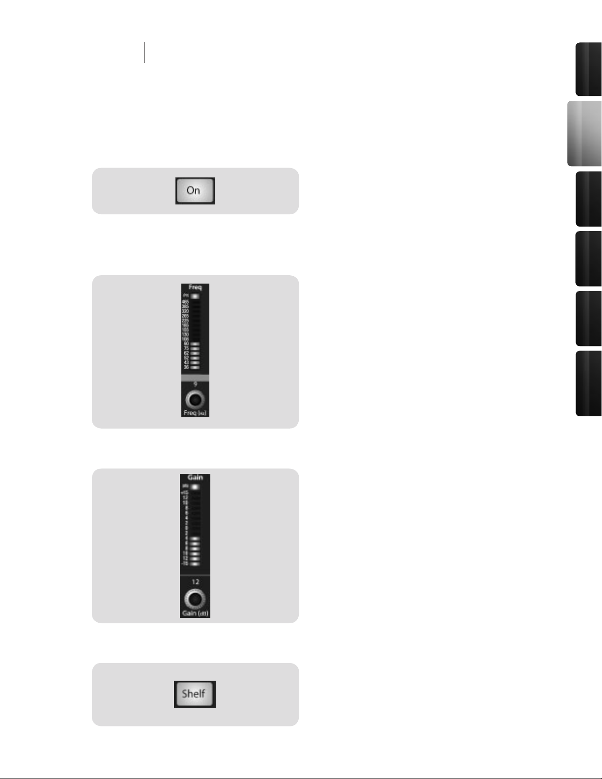
Low Shelf EQ Button
Turns on the Low Shelf EQ for the Selected Input or
Output Bus.
When the Shelf button is not engaged, the Low band is a
semi-parametric EQ. Enabling the Shelf button turns the
Low band into a low-shelving EQ that alters, by a xed
amount, a band of low frequencies at and below a userselected shelving frequency. It’s like a bass-control knob
on a stereo. In this mode, the Center Frequency control
selects the shelving frequency.
Low Band EQ Frequency Control
Sets and Displays the Center Frequency of the Low
Band EQ.
This encoder sets, and the meter displays, the center
frequency of the equalizer’s Low band. The center
frequency is the middle of the passband (the mean)
between the lower and upper cutoff frequencies that
dene the limits of the band.
You can adjust the center frequency from 36 to 465 Hz.
Activates Control for the Low Band EQ for the
Selected Input or Output Bus.
This button actives control of the equalizer’s Low band
for the selected channel or bus. The button will illuminate
to indicate control is active.
The Low Band EQ is available for all input and output
buses.
Low Band EQ Gain Control
28
29
2 Controls & Connections
2.3 The Fat Channel
2.3.2 Dynamics Processing and EQ
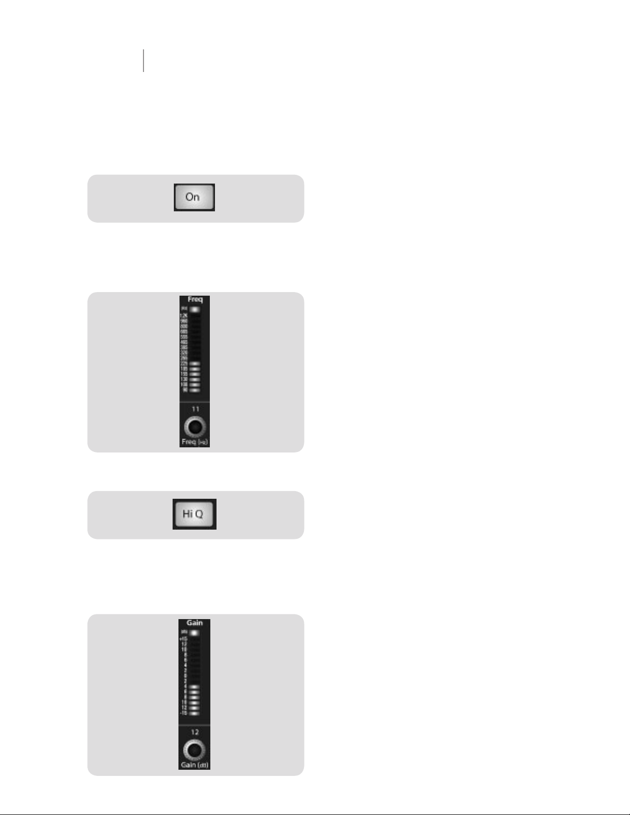
Low Mid EQ Button
Activates Controls for the Low Mid Band EQ for the
Selected Input or Output Bus.
This button actives the controls for the equalizer’s Low
Mid band for the selected input or output. The button will
illuminate to indicate control is active.
The Low Mid Band EQ is available for all input and output
buses.
Low Mid Band EQ Frequency
Control
Sets and Displays the Center Frequency of the Low
Mid Band EQ.
This encoder sets, and the meter displays, the center
frequency for the Low Mid band. You can adjust the
center frequency from 90 Hz to 1.2 kHz.
Hi Q Button
Enables a Narrow Bandwidth for the Low Mid Band
EQ on the Selected Input or Output.
Q is the ratio of the EQ band’s center frequency to its
bandwidth. With a constant center frequency, higher
Q values indicate a narrower bandwidth, so Q is often
equated with bandwidth. By default, the Q is set to
a value of 0.55. When the Hi Q button is engaged, the
Q setting will be increased to 2.0, thus narrowing the
bandwidth to provide more precise control.
Low Mid Band EQ Gain Control
Sets and Displays the Gain Attenuation or Boost of
the Center Frequency for the Low Mid Band.
This encoder sets, and the meter displays, the Gain cut
or boost at the center frequency of the Low Mid band.
The level of the center frequency can be set between -15
and +15 dB.
29
Control s &
Connect ions
Rec ordi ng
Tutori als
Technic al
Inf orma tion
Mul tipl e
Mixe rs
Ove rvie w
2 Controls & Connections
2.3 The Fat Channel
2.3.2 Dynamics Processing and EQ
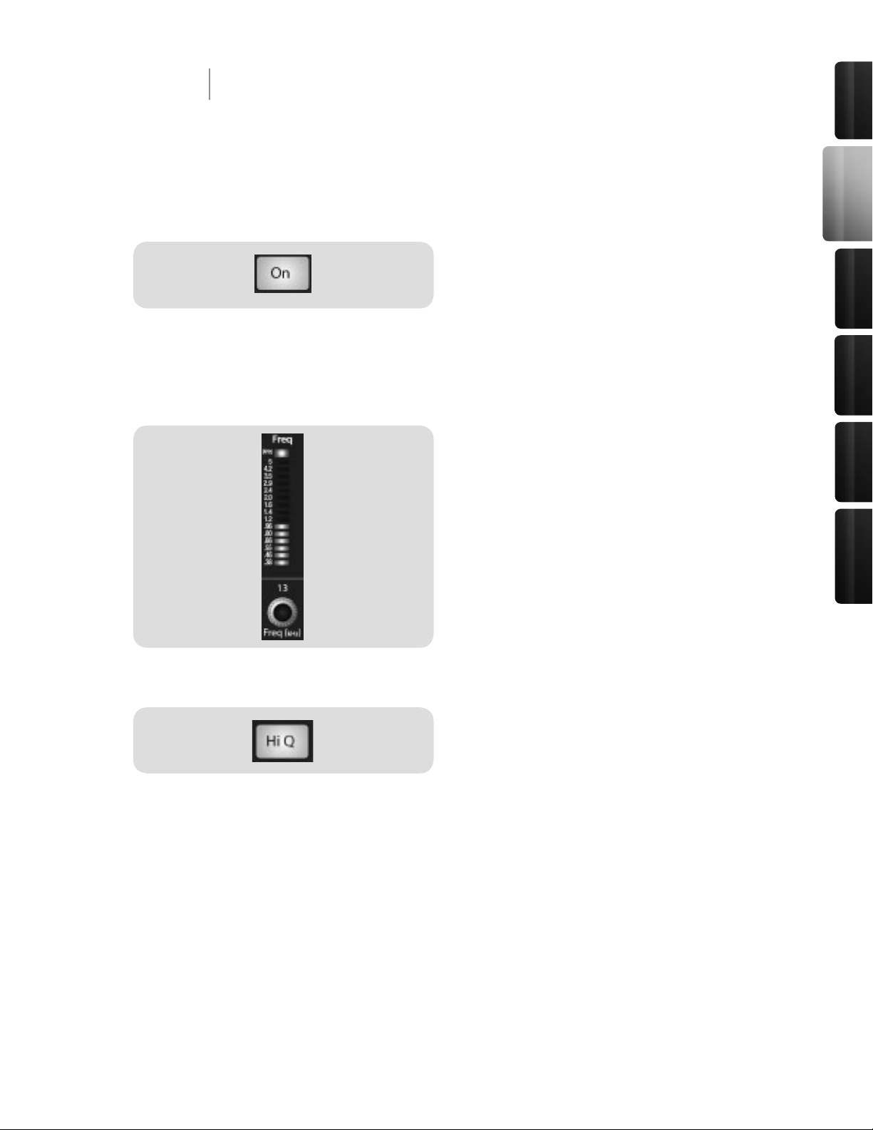
High Mid EQ Button
Activates Controls for the High Mid Band EQ for the
Selected Input or Output Bus.
This button actives the control for the High Mid band for
the selected input or output. The button will illuminate to
indicate that the control is active.
The High Mid Band EQ is available for all input and
output buses.
High Mid Band EQ Frequency
Control
Sets and Displays the Center Frequency of the High
Mid Band EQ.
This encoder sets, and the meter displays, the center
frequency of the High Mid band. You can adjust the Q
from 380 Hz to 5 kHz.
Hi Q Button
Enables a Narrow Bandwidth for the High Mid Band
EQ on the Selected Input or Output.
Q is the ratio of the EQ band’s center frequency to its
bandwidth. With a constant center frequency, higher Q
values indicate a narrower bandwidth. By default, the
High Mid EQ is set to a low Q = 0.55. When the Hi Q
button is engaged, the bandwidth will narrow to 2.0 to
provide more exact control.
30
31
2 Controls & Connections
2.3 The Fat Channel
2.3.2 Dynamics Processing and EQ
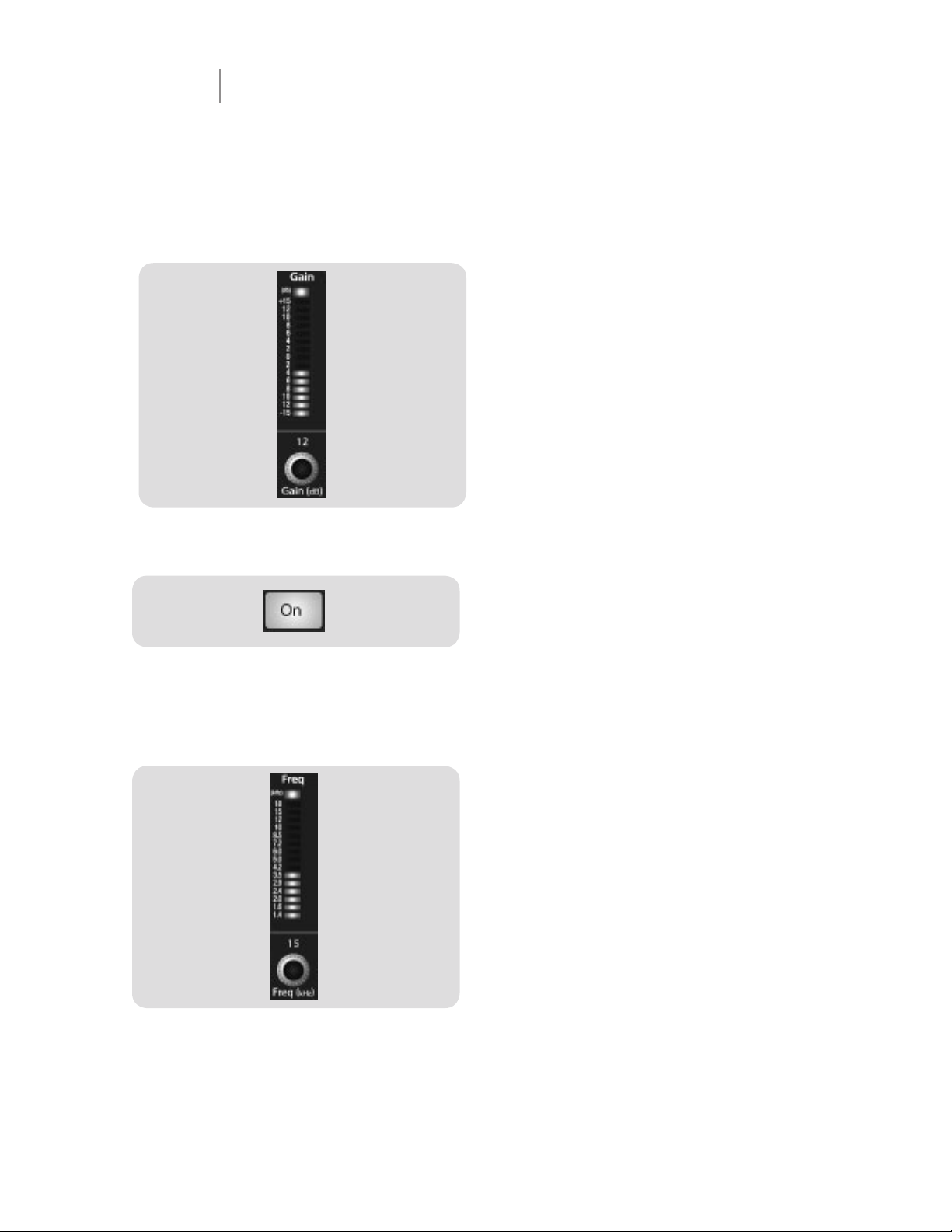
High Band EQ On/Off Button
Activates Control for the High Band EQ for the
Selected Input or Output Bus.
This button actives control of the High band for the
selected channel or bus. The button will illuminate to
indicate control is active.
The High Band EQ is available for all input and output
buses.
High Band EQ Frequency Control
Sets and Displays the Center Frequency of the High
Band EQ.
This encoder sets, and the meter displays, the center
frequency of the High band. You can adjust the center
frequency from 1.4 to 18 kHz.
High Mid Band EQ Gain Control
Sets and Displays the Gain Attenuation or Boost at
the Center Frequency.
This encoder sets, and the meter displays, the gain cut
or boost at the center frequency of the High Mid band.
The level of the center frequency can be set between -15
and +15 dB.
 Loading...