


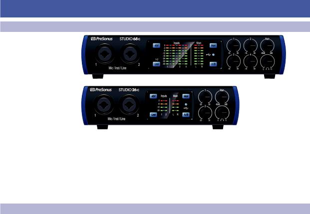
Studio 26c and Studio 68c
24-Bit, 192 kHz USB-C Audio Interfaces
Owner’s Manual
®
www.presonus.com
English

Table of Contents
1Overview — 1
1.1Introduction — 1
1.2About This Manual — 1
1.3Summary of Studio-series Hardware Features — 2
1.4Summary of Studio One Artist Software Features — 2
1.5What is in the Box — 3
2Hookup — 4
2.1Front-Panel Connections — 4
2.2Back Panel Connections — 6
2.3Connection Diagrams — 8
2.3.1Studio 26c — 8
2.3.2Studio 68c — 9
3Connecting to a Computer — 10
3.1Installation for Windows — 10
3.1.1Universal Control (Windows) — 10
3.1.2Loopback Recording (Windows only) — 12
3.2Installation for macOS — 13
3.3Using the Studio-series interfaces
with Popular Audio Applications — 13
4Studio One Artist Quick Start — 15
4.1Installation and Authorization — 15
4.2Setting Up Studio One — 16
4.2.1Configuring Audio Devices — 17
4.2.2Configuring MIDI Devices — 17
4.3Creating a New Song — 21
4.3.1Configuring Your I/O — 22
4.3.2Creating Audio and Instrument Tracks — 23
4.3.3Recording an Audio Track — 24
4.3.4Adding Virtual Instruments and Effects — 25
5Technical Information — 27
5.1Specifications — 27
6Warranty Information — 29
6.1How Consumer Law Relates To This Warranty — 29
1 |
Overview |
Studio 26c and Studio 68c |
1.1 |
Introduction |
Owner’s Manual |
1Overview
1.1Introduction
Thank you for purchasing a PreSonus® Studio-series audio interface. PreSonus Audio Electronics, Inc., has designed the Studio-series interfaces utilizing high-grade components to ensure optimum performance that will last a lifetime. Loaded with high-headroom, Class A microphone preamplifiers; a robust metering, Cue Mix A/B switching, high-definition 24-bit, 192 kHz conversion; and more, the Studio-series breaks new boundaries for music performance and production. All you need is a computer with a USB-C or USB-A (2.0 or 3.0) connection, a few microphones and cables, powered speakers, and your instruments, and you are ready to record!
1.2About This Manual
We suggest that you use this manual to familiarize yourself with the features, applications, and correct connection procedures for your Studioseries audio interface before trying to connect it to your computer.
This will help you avoid problems during installation and setup.
Many of the features and functions of the both Studio-series interface models are the same. When differences occur, the Studio 26c will be listed first, followed by the Studio 68c.
Throughout this manual you will find Power User Tips that can quickly make you a Studio-series interface expert.
1
1 |
Overview |
Studio 26c and Studio 68c |
1.3 |
Companion PreSonus Products |
Owner’s Manual |
1.3Companion PreSonus Products
Thanks for choosing PreSonus! As a solutions company, we believe the best way to take care of our customers (that’s you) is to ensure that you have the best possible experience from the beginning of your signal chain to the end. To achieve this goal, we’ve prioritized seamless integration throughout every design phase of these products from day one. The result is systems that communicate with each other
as intended—straight out of the box—without excessive configuration hassles. We’re here for you. Find out more at www.presonus.com.
2
1 |
Overview |
Studio 26c and Studio 68c |
1.4 |
What is in the Box |
Owner’s Manual |
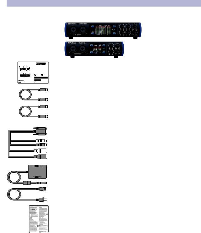
1.4What is in the Box
Your Studio-series package contains:
•• Studio 26c or Studio 68c 24-bit, 192 kHz audio interface
•• Quick Start Guide
Studio |
Audio |
Audio |
kHz |
•• 1M USB-C to C Cable
•• 1M USB-C to A Cable
•• MIDI / S/PDIF breakout cable (Studio 68c only)
•• External power supply (Studio 68c only)
PreSonus Health Safety and Compliance Guide
Power User Tip: All companion software and drivers for your PreSonus Studio-series audio interfaces are available for download from your My PreSonus user account. Please visit http://my.presonus.com and register your Studio-series interface to receive downloads and licenses.
3
2 |
Hookup |
Studio 26c and Studio 68c |
2.1 |
Front-Panel Connections |
Owner’s Manual |
2Hookup
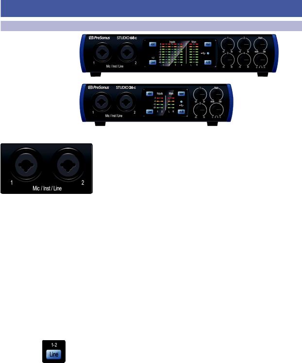
2.1Front-Panel Connections
Microphone Inputs. Your Studio-series interface is equipped with highquality microphone preamplifiers for use with all types of microphones. The Studio 26c features XMAX-L solid-state microphone preamps that are optimized for bus powering. The Studio 68c features XMAX microphone preamps with a Class A input buffer, followed by a dual-servo gain stage.
Every input channel on your Studio-series interface is equipped with combo jacks. This convenient connector accepts either a 1/4-inch or an XLR plug.
Instrument Inputs. The ¼-inch TS connectors on Channels 1 and 2 can be used with passive instruments (guitar, bass, etc.). See Input Source Button for more information.
Power User Tip: Active instruments are those that have an internal preamp or a line-level output. Active instruments should be plugged into a line input rather than into an instrument input. Plugging a line-level source into the instrument inputs not only risks damage to these inputs but also results in a very loud and often distorted audio signal
Line-level Inputs. The ¼-inch, balanced TRS connection accept linelevel inputs. Typical examples of line-level connections are synthesizer outputs, CD/DVD player outputs, and (with exceptions) signal-processor outputs. The first two ¼-inch inputs can be switched between line-level and instrument sources. See Input Source Button for more information.
Please note: As with any audio input device, plugging in a microphone or an instrument, or turning phantom power on or off, will create a momentary spike in the audio output. Because of this, we highly recommend that you turn down the channel trim before changing connections or turning phantom power on or off. This simple step will add years to life of your audio equipment.
Input Source Button. The first two input channels offer an Input Source button that lets you select instrument or line level for the ¼-inch inputs. When the button is illuminated, the input will accept a line-level source, such as a synthesizer or guitar amp modeler. Press this button to engage the instrument preamp when connecting guitars or a passive bass.
4
2 |
Hookup |
Studio 26c and Studio 68c |
2.1 |
Front-Panel Connections |
Owner’s Manual |
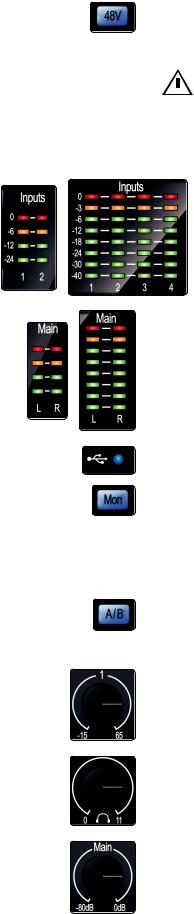
48 Volt Phantom Power. Studio-series interfaces provide 48V phantom power for the microphone inputs. Pressing the 48V button switches phantom power on and off for all microphone inputs; the button will illuminate in blue when phantom power is available on the microphone preamplifiers. .
WARNING: Phantom power is only required for condenser microphones and  can severely damage some dynamic mics, especially ribbon mics. Therefore, switch phantom power off when it is not required. Consult the user documentation
that came with your microphone before engaging phantom power.
XLR connector wiring for phantom power: Pin 1 = GND Pin 2 = +48V Pin 3 = +48V
Input Meters. These LED meters show the input level of the analog inputs on your Studio-series interface. The red Clip LED will illuminate when your input signal reaches -0.5 dBFS. At this level, the signal will begin to overload the analog-to-digital converters and exhibit signs of clipping. Use the gain controls to keep the signal below this level.
Output Meters. These meters display the signal level received from the first two driver returns (Main Left/Right). These meters have the same range as the input meters and display the signal level before the main output level control.
Sync LED. This light indicates if your Studio-series interface is in sync with your computer. When no sync is available, this light will flash red/blue.
Direct Monitor. The Direct button blends the source of what is heard through the Headphone and Main outputs in the following manner:
•• When Direct Monitoring is disabled, you’ll only hear the playback from your computer.
•• When Direct Monitoring is enabled, the button will illuminate blue, and you’ll hear a 50/50 blend of the playback from your computer and input source signals.
Cue A/B. This button allows you to switch the source that you listen to through your headphone output. When the button is not illuminated, playback streams 1 and 2 will be routed to the headphone output. Press the button to route playback streams 3 and 4 to your headphones instead.
Input Gain Control. These knobs adjust the gain for your audio interface inputs.
Headphone Level. This knob controls the level of the rear panel headphone output.
Main. The main knob controls the output level for the main left/right outputs on the back of your Studio-series interface and has a range of -80 dB to 0 dB. This control provides attenuation only.
5
2 |
Hookup |
Studio 26c and Studio 68c |
2.2 |
Back Panel Connections |
Owner’s Manual |
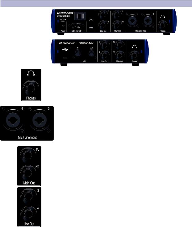
2.2Back Panel Connections
Headphone Output. The rear-panel headphone output can be switched between playback streams 1/2 and 3/4, the same streams as the Main left/right outputs and Outputs 3/4. These streams are switched via the Cue A/B button.
Mic/Line Inputs (Studio 68c). These mic/line combo connectors are for use with microphones on the XLR input and with line-level devices via the ¼-inch TRS connections.
Main Outs. These are the Main outputs for the Studio-series interface. The output level of the Main outputs is controlled by the Main level control on the front of the unit. Playback streams 1 and 2 are routed to these outputs.
Line Outputs. These ¼-inch, balanced line outputs allow you to route to external devices, such as headphone amps, signal processors, and additional monitors. Each output has an independent playback stream (Playback streams 3 and 4).
6
2 |
Hookup |
Studio 26c and Studio 68c |
2.2 |
Back Panel Connections |
Owner’s Manual |
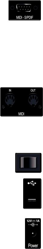
MIDI and S/PDIF Breakout-Cable Connector (Studio 68c). This is where you connect the breakout cable for the MIDI and S/PDIF I/O.
•• MIDI stands for“Musical Instrument Digital Interface.”However, MIDI can be used for many things other than instruments and sequencing. The MIDI inputs and outputs allow connection to a variety of MIDIequipped hardware, such as keyboard controllers, and can be used to send and receive MIDI Machine Control and MIDI Time Code.
Note: MIDI does not carry audio signals but is frequently used to trigger or control an audio source, such as a virtual instrument or hardware synthesizer. You should ensure that MIDI data is correctly sent and received by the appropriate hardware or software. You may also need to route hardware sound sources’ audio to the inputs of your Studio-series interface. Please consult the User’s Manual of your MIDI devices for help with MIDI setup and usage.
•• The S/PDIF standard allows transmission of 2 channels of up to 24-bit, 96 kHz audio. The S/PDIF I/O also allows your Studio 68c interface
to send and receive word clock to external digital devices.
MIDI I/O (Studio 26c). This is the MIDI input and output connections.
•• MIDI stands for“Musical Instrument Digital Interface.”However, MIDI can be used for many things other than instruments and sequencing. The MIDI inputs and outputs allow connection to a variety of MIDIequipped hardware, such as keyboard controllers, and can be used to send and receive MIDI Machine Control and MIDI Time Code.
Note: MIDI does not carry audio signals but is frequently used to trigger or control an audio source, such as a virtual instrument or hardware synthesizer. You should ensure that MIDI data is correctly sent and received by the appropriate hardware or software. You may also need to route hardware sound sources’ audio to the inputs of your Studio-series interface. Please consult the User’s Manual of your MIDI devices for help with MIDI setup and usage.
Power Switch (Studio 68c). This is the power switch for your Studio 68c.
USB-C Port. Use this port to connect your Studio 26c or 68c to your computer. While the Studio 26c and 68c connect using USB-C, both are fully compatible with USB 2.0 and 3.0 connections. Use the USB-C to A cable that came with your interface if your computer has a USB-A connection rather than a USB-C connection.
Please note: Studio-series interfaces are backward compatible with USB 2.0 and USB 3.0 speed connections. USB 1.1 is not supported. Studio 26c interfaces can be bus powered via USB-C or USB-A connections.
Power Connection (Studio 68c). This is where you connect the included 12V external power supply.
7

2 |
Hookup |
Studio 26c and Studio 68c |
2.3 |
Connection Diagrams |
Owner’s Manual |
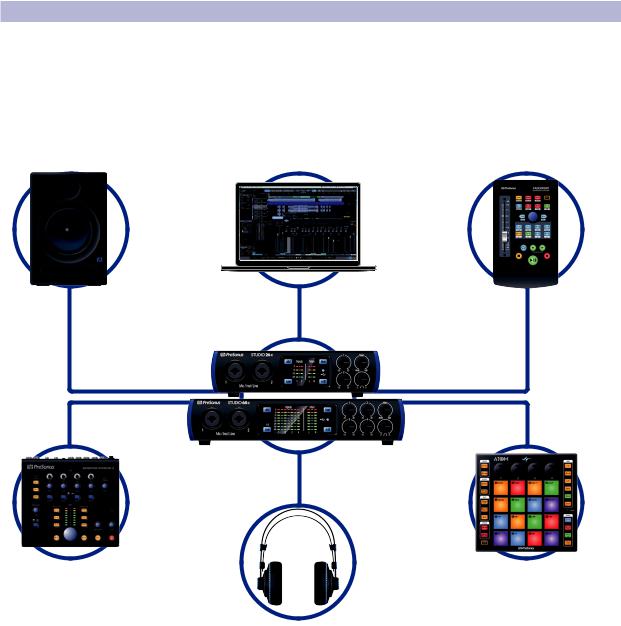
2.3Connection Diagrams
2.3.1 Studio 26c
See Studio 26 box for computer requirements
Vea los requerimientos de hardware en la caja de Studio 26
Systemvoraussetzungen siehe Studio 26 Packungsaufdruck
Voir la boîte de la Studio 26 pour les configurations informatiques requises
8
2 |
Hookup |
Studio 26c and Studio 68c |
2.3 |
Connection Diagrams |
Owner’s Manual |
2.3.2 Studio 68c
See Studio 68 box for computer requirements
Vea los requerimientos de hardware en la caja de Studio 68
Systemvoraussetzungen siehe Studio 68 Packungsaufdruck
Voir la boîte de la Studio 68 pour les configurations informatiques requises
9
 Loading...