


STUDIO CHANNEL
Vacuum Tube Channel Strip
User’s Manual
Version 1.1
© 2008, PreSonus Audio Electronics, Inc.
All Rights Reserved.

PRESONUS LIMITED WARRANTY
PreSonus Audio Electronics Inc. warrants this product to be free of defects in material and workmanship for a period of one year from the date of original retail purchase. This warranty is enforceable only by the original retail purchaser. To be protected by this warranty, the purchaser must complete and return the enclosed warranty card within 14 days of purchase. During the warranty period PreSonus shall, at its sole and absolute option, either repair or replace, free of charge, any product that proves to be defective on inspection by PreSonus or its authorized service representative. To obtain warranty service, the purchaser must first call or write PreSonus at the address and telephone number printed below to obtain a Return Authorization Number and instructions of where to return the unit for service. All inquiries must be accompanied by a description of the problem. All authorized returns must be sent to the PreSonus repair facility postage prepaid, insured and properly packaged. PreSonus reserves the right to update any unit returned for repair. PreSonus reserves the right to change or improve the design of the product at any time without prior notice. This warranty does not cover claims for damage due to abuse, neglect, alteration or attempted repair by unauthorized personnel, and is limited to failures arising during normal use that are due to defects in material or workmanship in the product. Any implied warranties, including implied warranties of merchantability and fitness for a particular purpose, are limited in duration to the length of this limited warranty. Some states do not allow limitations on how long an implied warranty lasts, so the above limitation may not apply to you. In no event will PreSonus be liable for incidental, consequential or other damages resulting from the breach of any express or implied warranty, including, among other things, damage to property, damage based on inconvenience or on loss of use of the product, and, to the extent permitted by law, damages for personal injury. Some states do not allow the exclusion of limitation of incidental or consequential damages, so the above limitation or exclusion may not apply to you. This warranty gives you specific legal rights, and you may also have other rights, which vary from state to state. This warranty only applies to products sold and used in the United States of America. For warranty information in all other countries please refer to your local distributor.
PreSonus Audio Electronics, Inc. 7257 Florida Blvd.
Baton Rouge, LA 70806 www.PreSonus.com
© 2008, PreSonus Audio Electronics, Inc.
All Rights Reserved.

TABLE OF CONTENTS
1 OVERVIEW |
|
|
1.1 |
Introduction ........................................................................................................................................... |
3 |
1.2 |
Features ................................................................................................................................................ |
4 |
1.3 |
What is in the Box ................................................................................................................................. |
5 |
2 CONTROLS & CONNECTIONS |
|
|
2.1 |
Front Panel Layout ................................................................................................................................ |
6 |
2.1.1 Tube Microphone Preamp ................................................................................................................. |
6 |
|
2.1.2 Compressor....................................................................................................................................... |
7 |
|
2.1.3 Parametric EQ.................................................................................................................................. |
8 |
|
2.1.4 Master and VU Meter ....................................................................................................................... |
9 |
|
2.2 |
Back Panel Layout ............................................................................................................................... |
10 |
3 OPERATION
3.1 |
Microphones ........................................................................................................................................ |
11 |
|
3.1.1 |
Condenser .................................................................................................................................... |
11 |
|
3.1.2 |
Dynamic ...................................................................................................................................... |
11 |
|
3.2 |
A Brief Tutorial on Dynamics Processing .............................................................................................. |
12 |
|
3.2.1 |
Common Questions Regarding Dynamics ....................................................................................... |
12 |
|
3.2.2 |
Types of Dynamic Processing ........................................................................................................ |
13 |
|
3.2.3 |
Vocabulary of Dynamics Processing .............................................................................................. |
14 |
|
3.2.4 |
General Compression Setting Suggestions...................................................................................... |
17 |
|
3.3 |
Equalizers ............................................................................................................................................ |
20 |
|
3.3.1 What is an EQ? ............................................................................................................................ |
20 |
||
3.3.2 |
How to Find the Best and Leave the Rest ...................................................................................... |
21 |
|
3.3.3 |
To Boost or Not to Boost ............................................................................................................. |
22 |
|
3.4 |
Application Settings............................................................................................................................... |
24 |
|
4 TECHNICAL INFORMATION
4.1 Specifications ...................................................................................................................................... |
27 |

OVERVIEW
1.1 INTRODUCTION
Thank you for purchasing the PreSonus Studio Channel. PreSonus Audio Electronics has designed the Studio Channel utilizing high-grade components to ensure optimum performance that will last a lifetime. The Studio Channel is a professional channel strip combining Class A tube preamplifier, VCA-based compressor and threeband parametric equalizer perfect for the professional and project studio. Great for all types of microphones, instruments, keyboards and synths, the Studio Channel has the sonic power and flexibility to achieve any tone you can dream of – luscious in your face vocals, crystal clear acoustic guitars, fat solid bass guitar, dynamic acoustic piano, cracking snare, punchy bass, huge MPC tracks,… you get the picture.
We encourage you to contact us at 225-216-7887 or at techsupport@presonus.com with any questions or comments you may have regarding your PreSonus Studio Channel. PreSonus Audio Electronics is committed to constant product improvement, and we value your suggestions highly. We believe the best way to achieve our goal of constant product improvement is by listening to the real experts, our valued customers. We appreciate the support you have shown us through the purchase of this product.
We suggest you use this manual to familiarize yourself with the features, applications and correct connection procedure for your Studio Channel before trying to connect it to your recording system. This will hopefully alleviate any unforeseen issues that you may encounter during installation and set up. Please pay close attention when connecting your Studio Channel to your system. Bad cables and improper grounding are the most common causes of problems encountered in recording and live P. A. environments. We recommend checking your cables, connections and grounding if you experience any noise or sonic performance problems.
Thank you, once again, for buying our product, and we hope you enjoy your Studio Channel!
3 | PreSonus 2007

OVERVIEW
1.2 FEATURES
The Studio Channel has everything needed to deliver big tone. The preamplifier stage of the Studio Channel is based on the award winning PreSonus BlueTube preamplifier with a high output 12AX7 vacuum tube operating on voltages double than all other preamplifiers in its class. It delivers high headroom and big tone, featuring dual control Gain and Tube Drive to create a wide range of sounds. The Studio Channel also comes loaded with a fully variable ultra-fast and smooth VCA-based compressor for musicality and ultra fast attack and parametric EQ that delivers sweet sounding gain/cut for ultra smooth highs, deep solid lows, and clear midrange. The Studio Channel is like a Swiss Army pocket knife giving you all the tools you need to tailor your tone to enhance your sound.
Summary of features
Class A vacuum tube microphone / instrument preamplifier
Tube gain and tube drive
Variable VCA compressor (threshold, ratio, attack, release, make up gain, auto, soft)
Three-band parametric EQ
Precision analog VU meter for gain reduction and output
EQ Pre/Post compressor switch
80Hz high pass filter
20dB pad
Phase invert
Rugged metal chassis
High headroom
Ultra low noise design
4 | PreSonus 2007
OVERVIEW
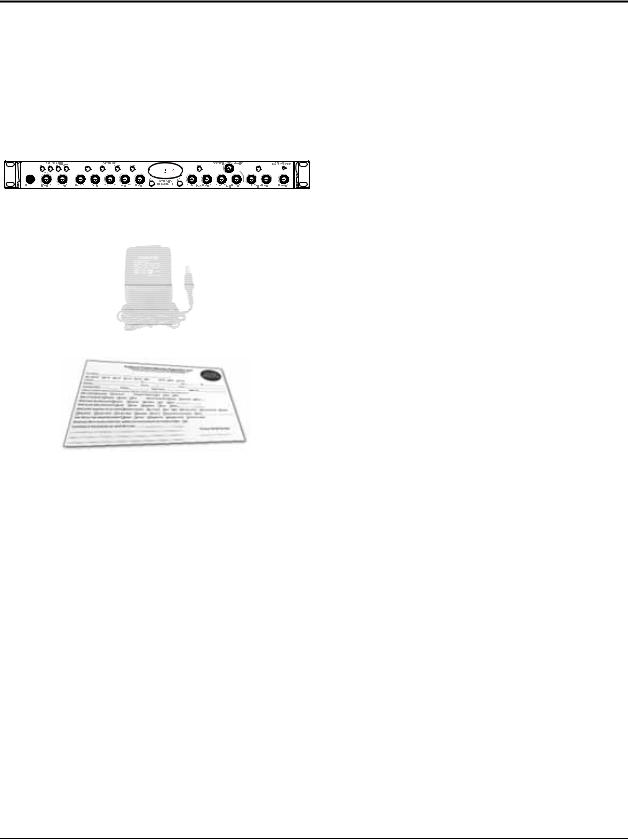
1.3 WHAT IS IN THE BOX
Your Studio Channel package contains the following:
Studio Channel
16VAC 1000mA Power Supply
PreSonus Warranty Card
5 | PreSonus 2007
CONTROLS AND CONNECTIONS
2.1FRONT PANEL LAYOUT
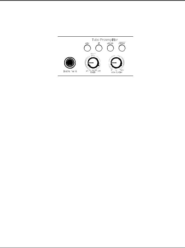
2.1.1Tube Microphone Preamp
Instrument Input. The ¼” TS connector on the front panel is for use with a passive instrument (guitar, bass, etc.). When an instrument is plugged into the instrument input, the microphone preamp is bypassed, and the Studio Channel becomes an active instrument preamplifier.
NOTE: Active instruments are those that have an internal preamp or a line level output. Active instruments should be plugged into a line input rather than into an instrument input. Plugging a line level source into the instrument inputs on the front of the Studio Channel not only risks damage to these inputs but also results in a very loud and often distorted audio signal.
(In other words, don’t plug a line level source into the front panel jack)
Input Gain/Trim Control. These knobs provide the following gain structure:
oXLR Microphone and TS Instrument/Hi-Z Inputs. 44 dB of variable gain (+10 dB to +54 dB)
Tube Drive. The Tube Drive control increases the amount of signal routed through the 12AX7 vacuum tube. (The gain controls overall volume, whereas the drive controls volume routed through the tube.) The effect achieved ranges from subtle to extreme, depending on the setting being used:
o“Warming Up the Sound”. This effect is achieved by adding in a small amount of Tube Drive (30% or less). It is especially desirable for vocals and electric bass. The resulting sound is richer and sweeter.
o“Overdriven Tube Sound”. This effect is achieved by adding in 30-100% of Tube Drive. The more Tube Drive you add, the more overdriven the sound will be. This sound is extremely useful in creating distorted guitar and that authentic “blues harp” harmonica sound.
48 Volt Phantom Power. This button enables phantom power to the XLR input.
XLR connector wiring for Phantom Power
Pin 1 = GND
Pin 2 = +48V
Pin 3 = +48V
6 | PreSonus 2007
CONTROLS AND CONNECTIONS
Phase Reverse. Reverses the polarity of the signal. Use the phase reverse when recording with more than one open microphones to combat phase cancellation between microphones.
-20 dB Pad. This button attenuates the input signal by 20 dB. The pad can be used to keep a hot signal from overdriving the microphone preamp.
80Hz Roll-off. The 80Hz button is a low-end roll-off filter. When pushed in, the 80Hz button causes all frequencies below 80Hz to be attenuated (dropped) by 12dB. This filter can be handy in live and studio applications. For example, the 80Hz filter can help to reduce the “boominess” or “muddiness” of a vocal and improve the overall clarity.
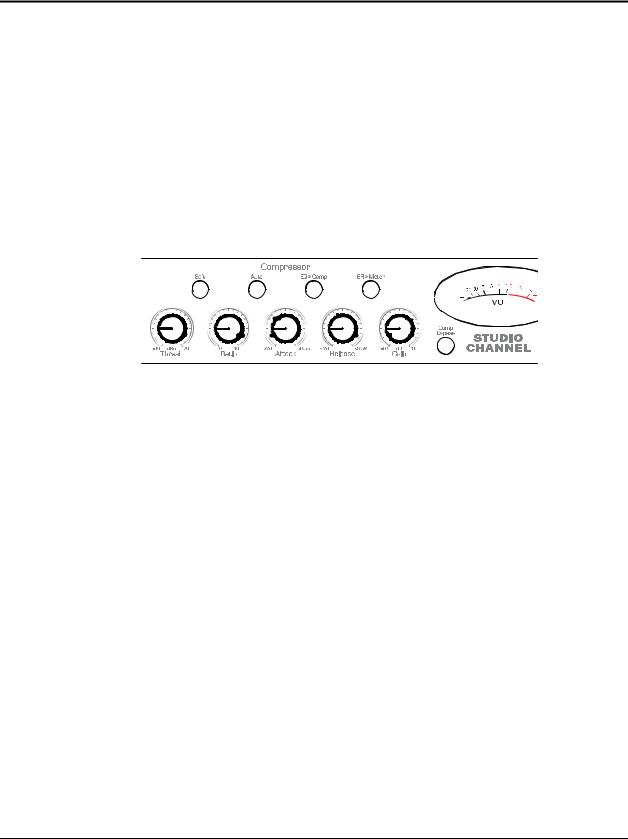
2.1.2 Compressor
Threshold. Sets the level at which compression begins. When the signal is above the Threshold setting, it becomes ‘eligible’ for compression. Basically, as you turn the Threshold knob counter-clockwise, the input signal is compressed (if you have a ratio setting of greater than 1:1). The threshold can be set from -40 to +20 dB.
Ratio. Sets the compression slope. This is defined as the output level versus the input level. For example, if you have the Ratio set to 2:1, any signal level above the Threshold setting will be compressed at a compression ratio of 2:1. This simply means that that for every 1dB of level increase into the compressor; the output will only increase ½ dB, thus producing an attenuation of 0.5 dB. The Ration can be set from 1:1 to 10:1.
Attack. Sets the speed at which the compressor ‘acts’ on the input signal. A slow attack time (fully clockwise) allows the beginning envelope of a signal (commonly referred to as the initial transient) to pass through the compressor uncompressed, whereas a fast attack time (fully counterclockwise) immediately subjects the signal to the Ratio and Threshold settings of the compressor.
Release. Sets the length of time the compressor takes to return the Gain reduction back to zero (no gain reduction). Very short Release times can produce a very choppy or ‘jittery’ sound, especially in low frequency instruments such as bass guitar. Very long Release times can result in an overly compressed signal (sometimes referred to as ‘squashing’ the sound). All ranges of Release can be useful at different times however and you should experiment to become familiar with the different sound possibilities.
Gain Make Up. When compressing a signal, gain reduction usually results in an overall reduction of level. The gain control allows you to restore the loss in level due to compression and readjust the volume to the pre-compression level (if desired). You can adjust the Gain Make Up from -10 to +10 dB.
7 | PreSonus 2007
 Loading...