


 Loading...
StudioLive™ 16.0.2
Performance and Recording Digital Mixer
Owner’s Manual
®
www.presonus.com
Hookup Getting Started Overview
Troubleshooting Resources Digital Effects Controls and Warranty Master Control
English
Important Safety Instructions
The exclamation point within an equilateral triangle is intended to alert the user to the presence of important operating and maintenance (servicing) instructions in this manual.
The lightning flash with arrowhead symbol within an equilateral triangle is intended to alert the user to the presence of uninsulated “dangerous”voltage
within the product’s enclosure that may be of sufficient magnitude to constitute a risk of electric shock to humans.
CAUTION: TO REDUCE THE RISK OF ELECTRIC SHOCK, DO NOT REMOVE THE COVER. NO USER-SERVICEABLE PARTS INSIDE. REFER SERVICING TO QUALIFIED PERSONNEL.
CAUTION: To reduce the risk of electric shock, do not expose this appliance to rain and moisture. The apparatus shall not be exposed to dripping or splashing
liquids and no object filled with liquids, such as vases, shall be placed on the
apparatus.
CAUTION: These service instructions are for use by qualified service personnel only. To reduce the risk of electric shock, do not perform any servicing other than
that contained in the operation instructions. Repairs must be performed by qualified service personnel.
1.Read these instructions.
2.Keep these instructions.
3.Heed all warnings.
4.Follow all instructions.
5.Do not use this apparatus near water.
6.Clean only with dry a cloth.
7.Do not block any ventilation openings. Install in accordance with the manufacturer’s instructions.
8.Do not install near any heat sources, such as radiators, heat registers, stoves, or other apparatus (including amplifiers) that produce heat.
9.Do not defeat the safety purpose of the polarized or grounding-type plug. A polarized plug has two blades, with one wider than the other. A grounding-type plug has two blades and a third grounding prong. The wide blade and the
third prong are provided for your safety. If the provided plug does not fit into your outlet, consult an electrician for replacement of the obsolete outlet.
10.Protect the power cord from being walked on or pinched, particularly at plugs, convenience receptacles, and the point where they exit from the apparatus.
11.Use only attachments/accessories specified by PreSonus.
12.Use only with the cart, stand, tripod, bracket, or table
specified by the manufacturer or sold with this apparatus. When a cart is used, use caution when moving the cart/ apparatus combination to avoid injury from tip-over.
13. Unplug this apparatus during lightning storms or when unused for long periods of time.
14.Servicing is required when the apparatus has been damaged in any way, such as if a power-supply cord or plug is damaged; or liquid has been spilled, or objects have fallen, into the apparatus; or if the apparatus has been exposed to rain or moisture, does not operate normally, or has been dropped. All PreSonus products in the USA should be serviced at the PreSonus factory in Baton Rouge, Louisiana. If your product requires a repair, contact support@presonus.com to arrange for a
return-authorization number. Customers outside the USA should contact their local distributor. Your distributor’s contact information is available at www.presonus.com.
15.The apparatus shall be connected to a Mains power outlet with a protective grounding/earthing connection.
16.Where the Mains plug or an appliance coupler is used as the disconnect device, the disconnect device shall remain readily operable.
EU Directives on the Protection of the
Environment and Other Euro Stuff
RoHS This product is compliant with the EU Directive 2011/65/EU for the Restriction of the use of Certain Hazardous Substances in Electrical and Electronic Equipment. No lead (Pb), cadmium (Cd), mercury (Hg), hexavalent chromium (Cr+6), PBB
or PBDE is intentionally added to this device. Any traces of impurities of these substances contained in the parts are below the RoHS specified threshold levels.
REACh This product is compliant with the European Union Directive EC1907/206 for the Registration, Evaluation, Authorization, and Restriction of chemicals (REACh) and contains none or less than 0.1% of the chemicals listed as hazardous chemicals in the REACh regulation.
WEEE This symbol on the product or its packaging indicates that this product must not be disposed of with other waste. Instead, it is your responsibility to dispose of your waste equipment by handing it over to a designated collection point for the recycling of waste electrical and electronic equipment. The separate collection and recycling of your waste
equipment at the time of disposal will help conserve natural resources and
ensure that it is recycled in a manner that protects human health and the environment. For more information about where you can drop off your waste equipment for recycling, please contact your local city recycling office or the dealer from whom you purchased the product.
CE This product complies with the European Union Council Directives and Standards relating to electromagnetic compatibility EMC Directive (2006/95/EC) and the Low Voltage Directive (2004/108/EC).

Table of Contents
1Overview — 1
1.1Introduction — 1
1.2About This Manual — 1
1.3Summary of StudioLive 16.0.2 Hardware Features — 2
1.4What is in the Box — 3
2Getting Started — 4
2.1Level Setting Procedure — 4
3Hookup — 9
3.1Rear-Panel Connections — 9
3.2Typical Live Band Hookup Diagram — 12
3.3Typical Recording Hookup Diagram — 13
4Controls — 14
4.1The Fat Channel — 14
4.1.1Select Buttons, Meters and the Fat Channel — 14
4.1.2Fat Channel
Processing Guide — 15
4.1.3Fat Channel: Dynamics Processing and EQ — 15
4.1.4Fat Channel Panning and Stereo Link — 20
4.1.5Fat Channel: Digital Out — 20
4.1.6Copying Fat Channel Settings — 21
4.1.7Loading Fat Channel Presets — 21
4.1.8Saving Fat Channel Presets — 22
4.1.9Channel Presets Library — 23
4.2Metering — 24
4.2.1StudioLive Metering Controls — 24
4.3Input Channel Strip — 25
4.3.1Input Channel Controls — 25
4.4Aux and FX Buses — 26
4.4.1Analog Aux Bus Controls — 26
4.4.2Internal FX Bus Controls — 27
4.4.3Aux and FX Bus Channel Sends — 27
4.4.4Creating Monitor Mixes — 29
4.4.5Creating Internal FX Mixes — 30
4.5MultiModes — 31
4.5.1MultiMode Controls and the Buttons that Love Them — 31
4.6Main Output Bus — 32
4.7Talkback System — 32
4.8Solo Bus — 33
4.8.1Solo Bus Controls — 33
4.8.2Using the Solo Bus for Monitoring — 34
4.8.3Using Solo in Place (SIP) to Set Up a Mix — 35
4.9Monitor Bus — 36
5Digital Effects | Master Control — 38
5.1The Digital FX (Effects) Menu — 38
5.1.1Creating FX Presets — 39
5.1.2Reverb and its Parameters — 40
5.1.3Delay and its Parameters — 41
5.1.4Digital Effects Preset Library — 42
5.1.5Digital Effects Types — 43
5.2Scenes — 44
5.2.1S1: Zero Out (Board Reset) — 44
5.2.2Creating a Scene — 45
5.2.3Scene Recall — 45
5.2.4Fader Locate — 47
5.2.5AutoStore — 47

5.3Graphic Equalizer — 48
5.3.1The Graphic EQ Menu and Controls — 49
5.3.2Saving and Loading GEQ Presets — 50
5.4System Menu — 50
5.5Using MIDI Control Mode to Remote-Control StudioLive — 52
5.5.1Recalling Scenes and FX Presets Remotely — 53
5.5.2Using Control Change Messages to Control Volume and FX Assignments — 53
5.5.3Controlling the StudioLive 16.0.2 with a Behringer FCB1010 — 54
5.5.4Controlling the StudioLive 16.0.2 with a Roland FC-300 — 57
6Resources — 60
6.1Stereo Microphone Placement — 60
6.2EQ Frequency Guides — 63
6.3Technical Specifications — 65
6.4StudioLive 16.0.2 Block Diagram — 68
6.5StudioLive 16.0.2 Recall Sheet — 70
7Troubleshooting
and Warranty — 71
7.1Trouble Shooting — 71
7.2PreSonus Limited Warranty — 72

StudioLive™ 16.0.2 Owner’s Manual
1Overview
1.1Introduction
Thank you for purchasing the PreSonus StudioLive™ 16.0.2 Performance and Recording Digital Mixer. PreSonus Audio Electronics has designed the StudioLive utilizing high-grade components to ensure optimum performance that will last a lifetime. Loaded with 12 high-headroom, XMAX™ microphone preamplifiers; a builtin 16x16 FireWire recording and playback engine; MIDI I/O; Fat Channel processing with 3-band semi-parametric EQs, compressors, limiters, and downward expanders; reverb and delay effects; 4 aux buses; extensive LED metering; mixer save/recall; channel-strip save/recall/copy/paste; talkback; and more, StudioLive breaks new boundaries for music performance and production. All you need is a computer with a FireWire connection, a few microphones and cables, speakers, and your instruments, and you are ready to record in the studio or in front of a live audience!
We encourage you to contact us with questions or comments regarding this product. PreSonus Audio Electronics is committed to constant product improvement, and we value your suggestions highly. We believe the best way to achieve our goal of constant product improvement is by listening to the real experts: our valued customers. We appreciate the support you have shown us through the purchase of this product.
For technical support, please see Section 7.1: Troubleshooting.
1.2About This Manual
We suggest that you use this manual to familiarize yourself with the features, applications, and connection procedures for your StudioLive before trying to connect it to your computer. This will help you avoid problems during installation and setup. This manual covers hardware functions for the StudioLive 16.0.2. A separate manual, also included with your StudioLive mixer, covers the StudioLive Software Library and connecting and using your StudioLive with a computer.
Throughout this manual you will find Power User Tips. These tips provide mix tricks that are unique to the StudioLive as well as explanations for various audio terms. In addition to the Power User Tips, you will find an assortment of audio tutorials at the back of this manual. These tutorials cover everything
from microphone placement to equalizer and compression-setting suggestions and are included to help you get the most from your StudioLive mixer.
Thank you, once again, for buying our product. We are confident that you will enjoy your StudioLive!
Hookup Getting Started Overview
Troubleshooting Resources Digital Effects Controls and Warranty Master Control
1

Hookup Started Getting Overview
Troubleshooting Resources Effects Digital Controls
Warranty and Control Master
1.3Summary of StudioLive 16.0.2 Hardware Features
1.3Summary of StudioLive 16.0.2 Hardware Features
•• 24-bit/48 kHz sampling rate
•• 12 Class A XMAX microphone preamplifiers
•• 16 line-level inputs
•• 4 auxiliary buses
•• High-definition analog-to-digital converters (118 dB dynamic range)
•• Unlimited-headroom, 32-bit floating-point, digital mixing and effects processing
•• 16x16 FireWire digital recording interface with two FireWire 400 (IEEE 1394) ports
•• Scene automation with load/save/recall of all settings
•• Fat Channel with:
•• High-pass filter
•• Compressor
•• Limiter
•• Downward expander
•• 3-band semi-parametric EQ
•• Pan, phantom power, polarity invert, load/save presets
•• Master effects processors (reverb and delay with Load and Save)
•• MIDI control over: Scene and FX Recall, FX to Main assign, Main Output, and FX Return Level
•• 60 mm faders
•• Military-grade quick-touch buttons
•• Fast-acting LED meters
•• Talkback communication system
•• Rugged steel chassis
•• Compatible with Cubase, Digital Performer, Logic, Nuendo, Sonar, Studio One®, and others
•• Windows® and Mac® compatible
•• Powerful StudioLive software library includes:
•• Virtual StudioLive (VSL) advanced editor/librarian/control
•• StudioLive Remote (SL Remote) remote control app for iPad® (free from Apple App Store)
•• QMix™ remote aux-mix app for iPhone®/iPod touch® (free from Apple App Store)
•• Capture™ integrated multitrack-recording software
•• Studio One® Artist digital audio workstation with more than 6 GB of plug-ins, loops, and sounds
2

StudioLive™ 16.0.2 Owner’s Manual
1.4What is in the Box
Your StudioLive package contains the following:
•• PreSonus StudioLive 16.0.2 digital recording and performance mixer
•• 6’(1.8 m) 6-pin-to-6-pin FireWire 400 cable
•• 6’(1.8 m) 6-pin-to-9-pin FireWire 400-to-800 cable
•• IEC power cord
•• StudioLive Software Library containing:
•• PreSonus Studio One Artist program DVD plus gigabytes of third-party content
•• PreSonus Capture CD with demo sessions
•• PreSonus Universal Control/Virtual StudioLive CD
•• StudioLive Software Library Manual
Hookup Getting Started Overview
Troubleshooting Resources Digital Effects Controls and Warranty Master Control
3
Hookup STartedrted GettingGetti Overview
Troubleshooting Resources Effects Digital Controls
Warranty and Control Master
2.1Level Setting Procedure
2 Getting Started
Before you begin, here are a few general rules of thumb:
•• Always turn the Main fader and both the Monitor and Phones knobs in the Monitor section down before making connections.
•• Before plugging or unplugging a microphone while other channels are active, mute the channel to which you are connecting.
•• Your faders should be set on or near the“U”mark whenever possible. The“U”indicates unity gain, meaning the signal is neither boosted nor attenuated. If the main output of your StudioLive is too high or too low when your faders are at or near unity, you can use the main output-level knob on the rear panel of the StudioLive to adjust the level up or down until you have achieved the optimal volume.
•• Do not allow your inputs to clip. Watch the level meters; when the LEDs near the Clip mark, the top LED will illuminate, indicating that the analog-to-digital converters are in danger of being overdriven. Overdriving the converters
will cause digital distortion, which sounds terrible. The XMAX™ preamps in your StudioLive provide plenty of headroom; take advantage of it.
Your P.A. and studio equipment should be powered on in the following order:
1.Sound sources (keyboards, direct boxes, microphones, etc.) connected to the StudioLive inputs
2.StudioLive mixer
3.Computer (if applicable)
4.Power amplifiers or powered monitors
When it’s time to power down, your system should be turned off in the reverse order. Now that you know what not to do, let’s get some audio going!
2.1Level Setting Procedure
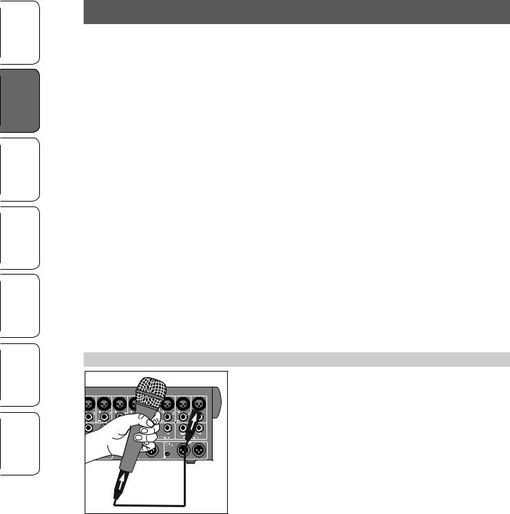
1. Grab a microphone and a mic cable and plug them into the StudioLive’s Channel 1 mic input.
4
StudioLive™ 16.0.2 Owner’s Manual
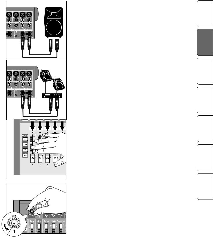
2.Connect the Main outs (TRS or XLR) of your StudioLive to your power amplifier or powered monitors.
3.If you’re using passive speakers, connect them to your power amplifier using speaker cable.
4.Bring down all the faders on your StudioLive to the ∞ setting.
5.Make sure that the Mic/Line knob on Channel 1 is all the way counter-clockwise.
Hookup GettingGet Startedted Overview
Troubleshooting Resources Digital Effects Controls and Warranty Master Control
5

Hookup STartedrted GettingGetti Overview
Troubleshooting Resources Effects Digital Controls
Warranty and Control Master
2.1Level Setting Procedure
6. Plug your StudioLive into a power outlet and turn it on.
7. If your microphone requires phantom power, engage the 48V button on Channel 1 of your StudioLive.
8. Turn on your amplifier or powered monitors.
6
StudioLive™ 16.0.2 Owner’s Manual
9.Press the Input button in the Meter section.
10.Speak or sing into your microphone at approximately the same volume you expect during the performance.
Hookup GettingGet Startedted Overview
Controls
11.Turn the trim knob on Channel 1 clockwise while watching the first meter in the Fat Channel.
12.Adjust the Channel 1 trim knob until a little more than half of the green LEDs are lit. The red LED at the top of the meter should never light up.
Troubleshooting Resources Digital Effects and Warranty Master Control
7

Hookup STartedrted GettingGetti Overview
Troubleshooting Resources Effects Digital Controls
Warranty and Control Master
2.1Level Setting Procedure
13. Press the Select button on Channel 1 and raise the Channel 1 fader until it reaches“U”(unity gain).
14. Bring up the Main fader until you can comfortably listen to your microphone through your speakers.
15. With Channel 1 selected, you can use the Fat Channel to add dynamics processing and EQ.
8
StudioLive™ 16.0.2 Owner’s Manual
3Hookup
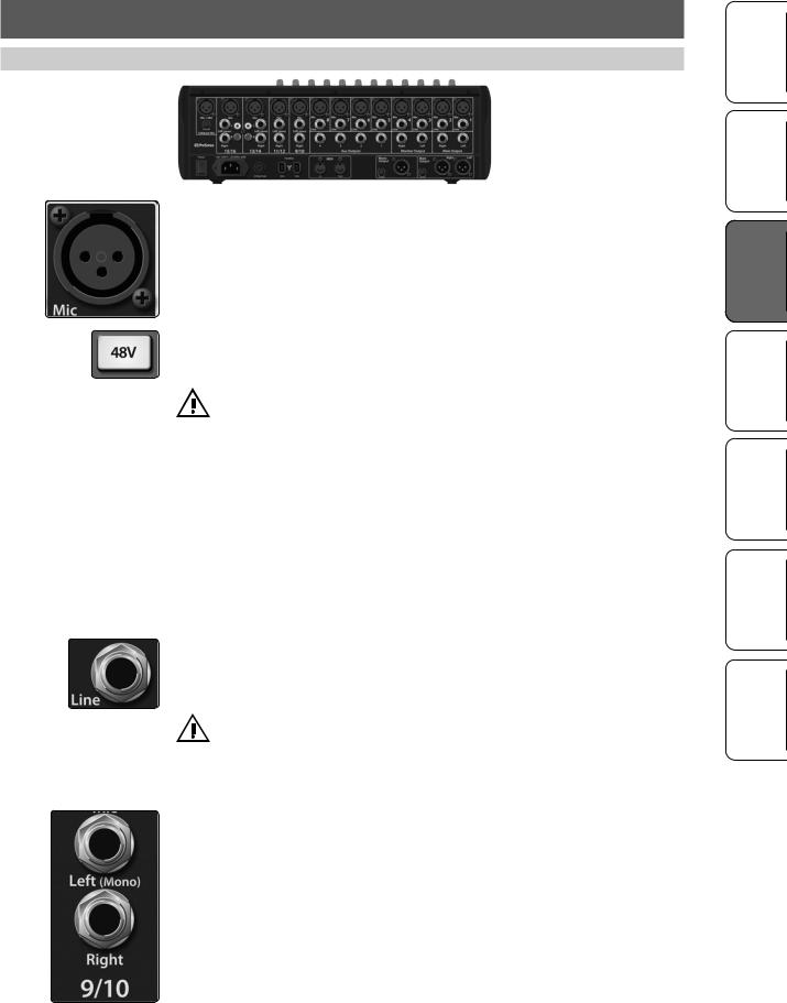
3.1Rear-Panel Connections
Microphone Inputs. Your StudioLive is equipped with 12 PreSonus XMAX microphone preamplifiers for use with all types of microphones. The XMAX preamplifier has a Class A input buffer, followed by a dual-servo gain stage. This arrangement results in ultra-low noise and wide gain control, allowing you to boost signals without increasing unwanted background noise.
48-volt Phantom Power. The StudioLive provides 48V phantom power for the microphone input on each channel. This feature can be individually enabled for each channel using the 48V button in the Fat Channel. See Section 4.1 for details.
WARNING: Phantom power is required for condenser microphones but can severely damage dynamic mics, especially ribbon mics. Therefore, switch
phantom power off for all channels where it is not required.
Power User Tip: Dynamic microphones and ribbon microphones are generally lower-output devices and require no external power source. The most important thing to note about ribbon microphones is that they very rarely require phantom power.
In fact, unless a ribbon microphone calls specifically for phantom power, sending phantom power to it can cause severe damage – probably beyond repair. Condenser microphones are generally more sensitive than dynamic and ribbon microphones and typically require external +48V phantom power. Always review your microphone’s documentation to ascertain the manufacturer’s recommended operating practices.
XLR connector wiring for phantom power: Pin 1 = GND Pin 2 = +48V Pin 3 = +48V
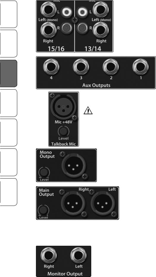
Line-level Input. Each channel of the StudioLive has a ¼ inch, balanced TRS connection for line-level input. When these inputs are engaged, the microphonepreamp circuit is bypassed. Typical examples of line-level connections are synthesizer outputs, CD/DVD-player outputs, and (with exceptions) signal-processor outputs.
Note: As with any mixer, plugging in a microphone or a line-level input device, or turning phantom power on or off, will create a momentary spike in the audio
output of your StudioLive. Because of this, it is highly recommended that you mute or turn down the channel trim before changing connections or turning phantom power on or off. This simple step will add years to life of your audio equipment.
Stereo Inputs. Channels 9 through 16 are stereo inputs. Each pair of channels is controlled by a single fader, Solo, Mute, and Select button. By default, Channels 9/10 through 15/16 are set to be mono, so that only the mic preamplifier for the Left (mono) input will be heard. When these channels are unlinked, the Right input is not accessible on the mixer. To insert the Right input into your mix, you must engage Stereo Link (see Section 4.1.4 for details).
Hookup Getting Started Overview
Troubleshooting Resources Digital Effects Controls and Warranty Master Control
9
Hookup Started Getting Overview
Troubleshooting Resources Effects Digital Controls
Warranty and Control Master
3.1Rear-Panel Connections
Channels 13/14 and 15/16 have unbalanced RCA connections, in addition to the balanced TRS connections. Like the TRS connections, the right RCA input will not be accessible on the mixer if the channels are not linked.
Aux Outputs. The StudioLive is equipped with four auxiliary outputs. In Section 4.4.4 and
4.4.5, we discuss in detail how to create aux mixes for monitoring and effects processing. Aux mixes are routed to these outputs.
Talkback Mic Input. The StudioLive does not have an onboard talkback mic; an external mic must be used. Phantom power is always enabled on this microphone preamp, so you can use either a dynamic or a condenser microphone.
Warning: Phantom power is only required for condenser microphones and can severely damage dynamic mics, especially ribbon mics. We recommend
that you consult the documentation that came with your microphone to confirm that it is safe to use with phantom power before connecting a dynamic microphone to the Talkback input.
Talkback Mic Trim. This is the trim control for your talkback microphone. It adjusts the gain of the Talkback input.
Mono Output. This balanced output carries a mono, summed version of the stereo signal from the main bus.
Mono Output Trim. This knob controls the maximum level of the
Mono Output signal. The signal can be attenuated to -80 dB and boosted up to +6 dB.
Main Output. The StudioLive features both XLR and TRS main outputs. These outputs are parallel to each other and to the mono output.
Power User Tip: All main outputs (XLR Stereo, TRS Stereo, and XLR Mono) of the StudioLive are active all the time. Because of this, you can send your main mix to five speakers
at the same time. This can be especially useful when you need to send a mix to another room or add another set of speakers to accommodate a larger venue.
Main Output Trim. This knob controls the maximum output level of the XLR and TRS main outputs. The signal can be attenuated to -40 dB and boosted up to 0 dB.
Monitor Output. These are the balanced control-room outputs. The level is controlled by the Monitor knob in the Monitor section on the top panel.
10
StudioLive™ 16.0.2 Owner’s Manual
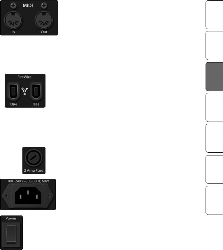
MIDI I/O. MIDI stands for“Musical Instrument Digital Interface.”However, MIDI has uses well beyond instruments and sequencing. The MIDI inputs and outputs allow connection to, and communication with, external MIDI equipment. One function of these ports is to serve as a standard MIDI interface, useful for sequencing and myriad other applications. The MIDI input can also be used to connect a MIDI footpedal to control certain parameters on your StudioLive. More information about MIDI Control Mode can be found in Section 5.5.
Power User Tip: MIDI data represents performance information and is not audio; however, it is frequently used to trigger or control an audio source, such as a plug-in or synthesizer. When using MIDI, please ensure that your MIDI data is correctly sent and received by the appropriate hardware or software instruments. You may also need to route those devices’ audio outputs to StudioLive input channels. Please consult the user’s manual of your MIDI devices for help with MIDI setup and usage.
FireWire Ports. There are two standard 6-pin FireWire 400 ports on the back of the StudioLive. Either port can be used to connect the StudioLive to a FireWire port on your computer. If your computer has a 4-pin connector (commonly found on laptops), you will need to purchase a 4-to-6-pin adapter or cable. These adapters and cables can be found at your local computer-supply store. The FireWire 400 ports are compatible with FireWire 800 connections found on Apple computers. Both a FW400-FW400 and a FW800-FW400 cable have been included for your convenience. You can use the second FireWire port to connect additional FireWire devices (such as external hard drives) to your computer or to daisy-chain a PreSonus FireStudio-family interface for additional recording inputs.
Note: Connecting FireWire 800 devices to the secondary FireWire connection is not supported. While connecting your StudioLive to your computer’s FireWire 800 connection using a 6-pin to 9-pin cable is supported,
your StudioLive will still operate at FireWire 400 bus speed.
2 Amp Fuse. This is the StudioLive’s fuse housing. Your StudioLive uses a 5 mm x 20 mm, 250 VAC, fast-acting fuse.
Power-Input. This is where you plug in the provided IEC power cable.
Power Switch. Push the top part of the switch ( | ) to turn on your StudioLive. Push the bottom part of the switch ( O ) to turn it off.
Hookup Getting Started Overview
Troubleshooting Resources Digital Effects Controls and Warranty Master Control
11

Hookup Started Getting Overview
Troubleshooting Resources Effects Digital Controls
Warranty and Control Master
3.2Typical Live Band Hookup Diagram
3.2Typical Live Band Hookup Diagram
|
Lead Vocal Mic |
|
|
Keyboard |
Rhythm Guitar and Amp |
Bass Guitar |
Drum Set |
100 - 240 VAC 50-60Hz |
On |
Laptop |
MIDI Pedal |
Monitors |
Front-of-House Speakers |
12

StudioLive™ 16.0.2 Owner’s Manual
3.3Typical Recording Hookup Diagram
Lead Vocal Mic
Rhythm Guitar and Amp |
Bass Guitar |
Drum Set |
100 -240 VAC 50-60Hz |
On |
PreSonus HP60 Headphone Distribution
Laptop
Reference Monitors
MIDI Controller
Hookup Getting Started Overview
Troubleshooting Resources Digital Effects Controls and Warranty Master Control
13
Hookup Started Getting Overview
Troubleshooting Resources Effects Digital Controls
Warranty and Control Master
4.1The Fat Channel
4Controls
4.1The Fat Channel
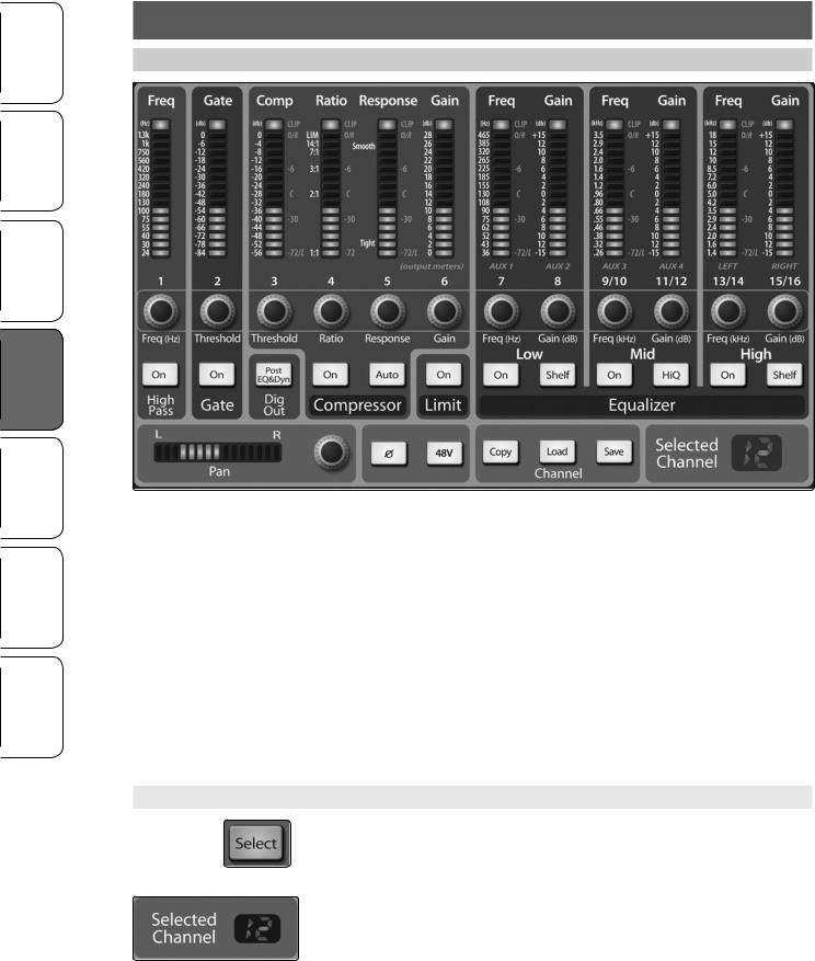
The revolutionary Fat Channel is the heart of the StudioLive. The Fat Channel makes dynamics, routing, and panning for every input and output on the StudioLive available at the touch of a Select button. The 12 multipurpose knobs and meters located in the Fat Channel control nearly every adjustment you will need to make on your StudioLive. From the Fat Channel, you can:
•• Add dynamics processing and EQ to every input and output
•• Create aux and effects mixes for all four analog aux buses and both internal effects buses
•• Engage phantom power for each mic preamp.
•• Meter input level and gain reduction for all 16 channels
•• Meter output level for all four aux buses and the Main output
•• Copy, save, and load Fat Channel and GEQ presets
•• Recall your fader position for stored mixes
4.1.1 Select Buttons, Meters, and the Fat Channel
Select Buttons. All around the StudioLive, you will see Select buttons. There is a Select button on each of the 12 channels, each of the 4 analog aux buses, both of the internal effects buses, and the main output bus. Each of these buttons serves exactly the same purpose: to access the Fat Channel parameters for its channel or bus.
Selected Channel Display. In the lower right corner of the Fat Channel, you will find an LED readout. The currently selected channel will always be displayed here. Numbers 1-8 indicate one of the 8 mono input channels is selected; 9, 11, 13, or 15 indicate that one of the 4 stereo input channels is selected; MA indicates the Main bus; A1-A4 indicates Aux 1-4; and Fa and Fb indicate EFX A and EFX B.
14
StudioLive™ 16.0.2 Owner’s Manual
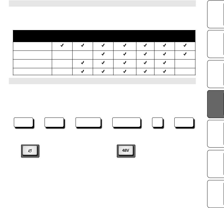
4.1.2 Fat Channel Processing Guide
The following table provides a quick guide to the processing that is available for each bus in the StudioLive, as well as which inputs and buses are available for recording. For more information on FireWire sends, please see Section 2.5 in the Software Library Reference Manual.
Bus |
Polarity |
High-Pass |
Noise |
Compressor |
EQ |
Limiter |
FireWire |
|
Invert |
Filter |
Gate |
|
|
|
Send |
Input Channels
Main Out L/R
Aux Busses
Internal FX Send Mix
4.1.3 Fat Channel: Dynamics Processing and EQ
The main function of the Fat Channel is to provide dynamics processing and filtering for every input and output on the StudioLive. The rotary encoders work in conjunction with the meters directly above them to adjust the dynamics processing and EQ. The Fat Channel’s processing section consists of five parts: High-Pass filter, Noise Gate, Compressor, Limiter, and Semi-Parametric EQ. Each can be turned on or off and controlled separately. The signal flows as follows:
Phase  Hi-Pass
  Noise Gate
  Compressor
  EQ
EQ  Limiter
Polarity Invert Button. Inverts the Polarity of the Selected Channel.
Push this button to invert the polarity of the selected channel’s signal (that is, to alter the polarity by 180°). The button will illuminate, indicating that Polarity Invert is active. The Polarity Invert button can be used to correct audio signals that are out of phase and are
cancelling/reinforcing each other.
Power User Tip: When recording with more than one open microphone, use the polarity invert to combat phase cancellation between microphones.
Polarity Invert is only available on the 16 channels of the input bus.
48V Button. Engages Phantom Power in the Microphone Preamp of the Selected Channel.
Push this button to engage phantom power in the selected channel’s microphone preamp. The button will illuminate, indicating that phantom power is active. Phantom power transmits 48V of DC electric power through a microphone cable.
The 48 volts supplied by way of the XLR input provides power for condenser microphones and other devices requiring continuous phantom power. This power is supplied at a constant level to prevent
any signal degradation.
Phantom power is only available on the 12 microphone preamps of the input bus.
Hookup Getting Started Overview
Troubleshooting Resources Digital Effects Controls and Warranty Master Control
15

Hookup Started Getting Overview
Troubleshooting Resources Effects Digital Controls
Warranty and Control Master
4.1The Fat Channel
High Pass Filter On/Off. Turns the High Pass Filter On/Off for the Selected Channel or Output Bus.
This button engages and disengages the high-pass filter for the selected channel or output bus. It will illuminate to indicate that the high-pass filter has been enabled.
The high-pass filter is available on the 16 channels of the input bus, the 4 aux buses, and both internal FX buses.
High Pass Filter Frequency.
Adjusts the High Pass Filter’s Cutoff Frequency.
The High Pass Filter section consists of an encoder and a meter. Frequency range is indicated to the left of the
meter. The filter’s threshold can be set from 24 Hz to 1 kHz.
The High Pass Filter’s slope is -6 dB/octave.
Power User Tip: A high-pass filter attenuates all frequencies below the set threshold. Use the Fat Channel High Pass Filter to remove unwanted low-frequencies from your source signal, rather than trying to EQ them out.
Gate On/Off Button.
Turns the Gate On/Off for the Selected Channel.
This button engages and disengages the gate for the selected channel. It will illuminate to indicate that the gate has been enabled.
The gate is available for all input and output buses.
Power User Tip: The “Gate” in your StudioLive 16.0.2 is actually a downward expander. In contrast to compression, which decreases the level of a signal after it rises above the compression threshold, expansion decreases the level of a signal after the signal goes below the expansion threshold. Commonly used
for noise reduction, the major difference between expansion and noise gating is that expansion
is dependent on the signal level after the level crosses the threshold, whereas a noise gate works independent of a signal’s level beyond the threshold.
Gate Threshold. Sets and Displays the Threshold of the Gate for the Selected Channel.
This encoder sets, and the meter displays, the gate threshold
for the selected channel. The threshold determines the level at which the gate will open. Essentially, all signals above the threshold setting are passed through unaffected. You can set the threshold from 0 to -56 dB.
Power User Tip: If the threshold is set fully counterclockwise, the gate is turned off (always open), allowing all signals to pass through unaffected.
Compressor On/Off. Turns the Compressor On/Off for the Selected Channel or Output Bus.
This button engages or disengages the compressor for the selected channel or output bus. It will illuminate to indicate that the compressor has been enabled.
The compressor is available for all input and output buses.
Power User Tip: A compressor is a type of amplifier in which gain is dependent on the signal level passing through it. You can set the maximum level a compressor allows to pass through, thereby causing automatic gain reduction above some predetermined signal level, or threshold. Compression refers, basically, to the ability
to reduce, by a fixed ratio, the amount by which a signal’s output level can increase relative to the input level. It is useful for lowering the dynamic range of an instrument or vocal, making it easier to record without distorting the recorder. It also assists in the mixing process by reducing the amount of level changes needed for a particular instrument.
16
Compressor Auto Mode Button. Enables Automatic Response Mode.
When Auto mode is active, the Response control becomes inoperative, and a preprogrammed attack and release curve is used. In this
mode, the attack is set to 10 ms, and the release is set to 150 ms. All other compressor parameters can still be adjusted manually.
Compressor Threshold. Sets and Displays the Threshold of the Compressor for the Selected Channel or Output Bus.
This encoder sets, and the meter displays, the compressor threshold for the selected channel or output bus. When the signal’s amplitude (level) exceeds the threshold setting,
the compressor engages. Turning the knob counterclockwise lowers the threshold so that compression begins at a lower amplitude. The threshold can
be set from -56 to 0 dB.
Compression Ratio. Sets and Displays the Compression Ratio for the Selected Input Channel or Output Bus.
This encoder sets, and the meter displays, the compression ratio (or slope) for the selected channel or output bus. The ratio sets the compression slope, which is a function of the output level versus the input level. For example, if you have the ratio set to 2:1, any signal levels above the threshold setting will be compressed at a ratio of 2:1. This
means that for every 2 dB of level increase above the threshold, the compressor’s output will only increase 1 dB. The ratio
can be set from 1:1 to 14:1.
StudioLive™ 16.0.2 Owner’s Manual
Compressor Response. Sets and Displays the Compressor Response Setting for the Selected Input Channel or Output Bus.
This encoder sets, and the meter displays, the compressor’s response setting for the selected channel or output bus. The Response control sets the attack and release tapers for the Compressor simultaneously. A tight response time triggers the compressor immediately and returns the gain reduction back to zero quickly when the signal drops below the compressor threshold. A smooth response time allows the beginning component of the signal or
“initial transient”to pass through, uncompressed, and extends the time of length of time before the gain reduction returns to zero.
Power User Tip: In general, a tighter response time should be used for instruments with relatively few transients, like drums and percussion, while a smooth setting should be using for instrument with a lot of transients, like vocals and stringed instruments.
Compressor Makeup Gain. Sets and Displays the Amount of Makeup Gain for the Compressor on the Selected Input Channel or Output Bus.
This encoder sets, and the meter displays, the makeup-gain setting of the compressor for the selected channel or output bus. When compressing a signal, gain reduction usually results in an overall attenuation of level. The gain control allows you to restore this loss in level and readjust the volume to the precompression level (if desired). You can adjust Makeup Gain from 0 dB (no
gain adjustment) to +28 dB.
Hookup Getting Started Overview
Troubleshooting Resources Digital Effects Controls and Warranty Master Control
17
Hookup Started Getting Overview
Troubleshooting Resources Effects Digital Controls
Warranty and Control Master
4.1The Fat Channel
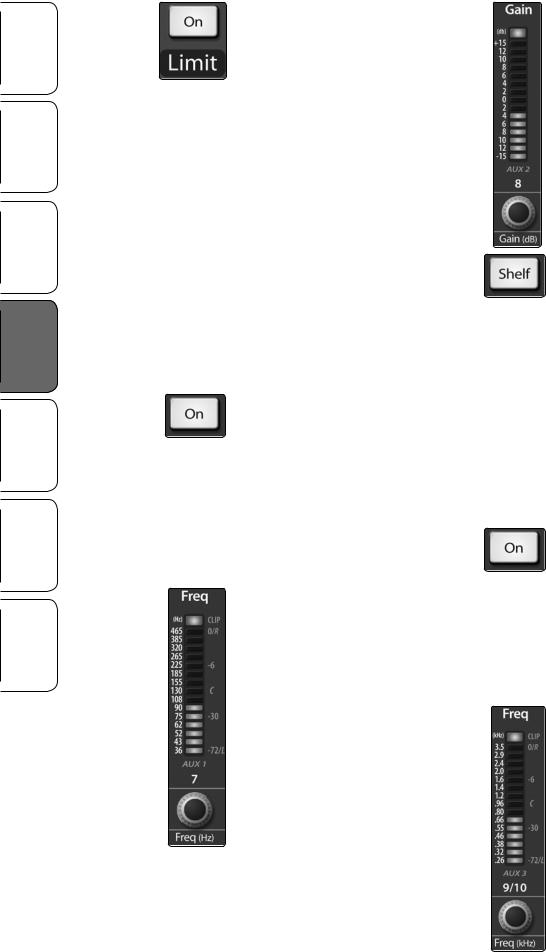
Limiter On/Off. Turns on the Limiter for the Selected Input Channel or Output Bus.
When the limiter is engaged the button will illuminate. The threshold for the limiter is set to 0 dBFS. The Ratio is ∞:1.
The limiter is available for all input and output buses.
Power User Tip: At the simplest level, a limiter is a compressor that is set to prevent any increase in the level of a signal above
the threshold. For example, if you have the threshold knob set at 0 dB, and the ratio turned fully clockwise, the compressor
becomes a limiter at 0 dB, so that the output signal cannot exceed 0 dB regardless of the level of the
input signal. Typically, compression ratios of 10:1 and above are considered to be limiting.
Low EQ On/Off Button.
Activates Control for the Low Band EQ for the Selected Input or Output Bus.
This button actives control of the equalizer’s Low band for the selected channel or bus. The button will illuminate to indicate the band is active.
The Low EQ band is available for all input and output buses.
Low EQ Frequency Control. Sets and Displays the Center Frequency of the Low EQ Band.
This encoder sets, and the meter displays, the center frequency of the equalizer’s Low band. The center frequency is the middle of the passband (the mean) between the lower and upper cutoff frequencies that define the limits of the band.
You can adjust the center frequency from 36 to 465 Hz.
Low EQ Gain Control. Sets and Displays the Gain Attenuation or Boost of the Center Frequency.
This encoder sets, and the meter displays, the gain cut or boost at the center frequency for the Low band. The level of the center frequency can be set between -15 and +15 dB.
Low Shelf EQ Button. Turns on the Low Shelving EQ for the Selected Input or Output Bus.
When the Shelf button is not engaged, the Low band is semiparametric. Enabling the Shelf button turns the Low band into a low-shelving EQ that alters, by a fixed amount, a band of low frequencies at and below a
user-selected shelving frequency.
Power User Tip: A low shelving EQ is like a bass-control knob on a stereo. In this mode, the Center Frequency control selects the shelving frequency.
Mid EQ On/Off Button. Activates Controls for the Mid EQ for the Selected Input or Output Bus.
This button actives the controls for the equalizer’s Mid band for the selected input or output.
The button will illuminate to indicate the band is active.
The Mid EQ band is available for all input and output buses.
Mid EQ Frequency Control. Sets and Displays the Center Frequency of the Mid EQ.
This encoder sets, and the meter displays, the center frequency for the Mid band. You can adjust the center frequency from 260 Hz to 3.5 kHz.
18
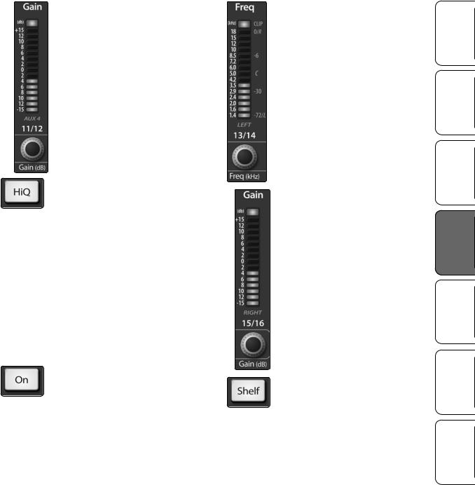
Mid EQ Gain Control. Sets and Displays the Gain Attenuation or Boost of the Center Frequency for the Mid Band.
This encoder sets, and the meter displays, the gain cut or boost at the center frequency of the Mid band. The level of the center frequency can be set between -15 and +15 dB.
Mid Hi Q Button. Enables a Narrow Bandwidth for the Mid Band EQ on the Selected Input or Output bus.
Q is the ratio of the EQ band’s center frequency to its bandwidth. With a constant center frequency, higher Q values indicate a narrower bandwidth, so Q is often equated with bandwidth. By default, the Q is set to a value of 0.55. When the Hi Q button is engaged, the Q setting will be increased to 2.0, thus narrowing the bandwidth to provide more precise control.
High EQ On/Off Button.
Activates Control for the High EQ for the Selected Input or
Output Bus.
This button actives control of the High band for the selected channel or bus. The button will illuminate to indicate the band is active.
The High EQ band is available for all input and output buses.
StudioLive™ 16.0.2 Owner’s Manual
High EQ Frequency Control.
Sets and Displays the Center Frequency of the High EQ.
This encoder sets, and the meter displays, the center frequency of the High band. You can adjust the center frequency from 1.4 to 18 kHz.
High EQ Gain Control. Sets and Displays the Gain Attenuation or Boost at the Center Frequency of the High EQ Band.
This encoder sets, and the meter displays, the gain cut or boost at the center frequency of the High EQ band. The level of the center frequency can be set between -15 and +15 dB.
High Shelf EQ Button. Turns on the High Shelving EQ for the Selected Input or Output Bus.
When the Shelf button is not engaged, the High band is a semi-parametric EQ. Enabling the Shelf button turns the High band into a high shelving EQ that alters, by a fixed amount, a band of high frequencies
at and above a user-selected shelving frequency.
Power User Tip: A high shelving EQ is like a treble-control knob on a stereo. In this mode, the Center Frequency control selects the shelving frequency.
Hookup Getting Started Overview
Troubleshooting Resources Digital Effects Controls and Warranty Master Control
19

Hookup Started Getting Overview
Troubleshooting Resources Effects Digital Controls
Warranty and Control Master
4.1The Fat Channel
4.1.4 Fat Channel Panning and Stereo Link
|
|
The Pan control for each input or output bus is set |
|
|
on the Fat Channel. The LED display shows the Pan |
|
|
setting, and the encoder to the right of the display |
|
|
controls panning for the selected input or output bus. |
|
|
When two channels are linked as stereo pair, the LED |
|
|
display will automatically change to a stereo pan. |
|
Stereo linking is also done from within the Fat Channel. Input channels and aux |
|
|
buses can be linked to create a stereo pair. The stereo pairs are predefined and |
|
|
cannot be changed. They are as follows: |
|
|
|
|
Channels 1 and 2 |
|
Channels 11 and 12 |
|
|
|
Channels 3 and 4 |
|
Channels 13 and 14 |
|
|
|
Channels 5 and 6 |
|
Channels 15 and 16 |
|
|
|
Channels 7 and 8 |
|
Aux 1 and Aux 2 |
|
|
|
Channels 9 and 10 |
|
Aux 3 and Aux 4 |
|
|
|
|
For mono channels and aux buses, a stereo link can be enabled when either channel |
|
|
in the pair is selected. When the Stereo Link button is illuminated, all dynamics |
|
|
and EQ settings are nondestructively pasted to the other channel in the pair. |
|
|
Power User Tip: Note that this is a nondestructive paste; when the Link button is |
|
|
disengaged, the other channel‘s previous settings will be restored. For instance, if Channel |
|
|
8 is selected when the Stereo Link button is engaged, all of Channel 8’s settings will be |
|
|
copied onto Channel 7. If Channel 7 is selected when the Stereo Link button is engaged, |
|
|
Channel 7’s settings will be copied onto Channel 8. Because the settings are copied |
|
|
nondestructively, it is possible to A/B dynamics settings with the touch of two buttons. |
|
|
Whichever channel is selected when the Link button is engaged will be |
|
|
the Link Master. When either channel in the stereo link is selected, both |
|
|
channels’Select buttons will illuminate but the Link Master‘s ID number will |
|
|
be displayed in the Selected Channel LED read-out in the Fat Channel. |
|
|
On the StudioLive 16.0.2’s four stereo channels, the stereo link will enable the right |
|
|
side (channels 10, 12, 14, and 16) to be heard in your mix. Each of these stereo |
|
|
channels’fader, Select button, MultiMode button, and Aux send controls both |
|
|
channels at the same time. All Fat Channel settings are applied to both channels. |
|
|
Power User Tip: It should be noted that while Stereo Link must be enabled in order to |
|
|
hear the right side of each stereo channel through the StudioLive, the right inputs are |
|
|
still sent through the FireWire bus and can be recorded by your DAW with or without |
|
|
Stereo Link engaged. For more information on using your StudioLive as an audio |
|
|
interface, please consult Section 2 in the StudioLive Software Library Reference Manual. |
|
4.1.5 Fat Channel: Digital Out
The Fat Channel also gives you the option of sending just the unprocessed audio to your computer or including the Fat Channel settings in the recorded signal. When the Dig Out button is enabled, the signal being sent to the FireWire bus is post-EQ and post-dynamics processing; the button will illuminate to indicate this signal flow. When the button is disabled, the signal being sent to the FireWire bus is pre-Fat Channel.
The Dig Out button is only available when one of the channel inputs is selected. The Main bus automatically sends its signal post-Fat Channel dynamics and EQ. All FireWire sends are pre-fader except for the Aux and Main outputs.
For more information on using your StudioLive as an audio interface, please consult Section 2 in the StudioLive Software Library Reference Manual.
20
Loading...