


 Loading...
Repair Manual
636/636AF Instant Camera
December 1995
Americas Business Center
Technical Services
201 Burlington Road
Bedford MA 01730
TEL: 1.781.386.5309
FAX: 1.781.386.5988
[This page intentionally blank]
Model 636 Camera Service Manual
CONTENTS
Section |
Page |
|
1 |
General Description |
1 |
2 |
Sequence of Operation |
3 |
3 |
Theory of Operation |
13 |
4 |
Disassembly & Reassembly |
36 |
5 |
Troubleshooting |
75 |
6 |
Testing with the Star Tester, |
|
|
Camera Adjustments and Tester |
|
|
Calibration |
85 |
7 |
Testing with the B-600 Tester, |
|
|
Camera Adjustments and Tester |
|
|
Calibration |
106 |
PARTS CATALOG: Separate document.
See Polaroid Model 636 CAMERA PARTS CATALOG, January 1994 for part names, numbers and exploded views.
i
|
|
|
LIST OF ILLUSTRATIONS |
|
Figure |
Description |
|
Page |
|
(SECTION 1 Model 636 Description) |
|
|||
- |
636 Camera |
|
1 |
|
(SECTION 2 Sequence of Operation) |
|
|||
- |
Flash charging, fire & exposure switches |
3 |
||
- |
Strobe charging |
3 |
||
- |
Strobe ready sequence |
4 |
||
- |
Exposure sequence |
4 |
||
- |
Exposure sequence: clock & photocell |
5 |
||
- |
Fill flash sequence |
5 |
||
- |
Flash quench, shutter closing |
6 |
||
- |
Motor drive of pick, counter, S5 actuator |
6 |
||
- |
Low ambient exposure sequence |
7 |
||
- |
Subject near/far determination |
7 |
||
- |
“ |
“ |
“ |
8 |
- |
Low light near exposure control |
8 |
||
- |
Motor drive of pick, counter, S5 actuator |
9 |
||
- |
Subject far determination |
9 |
||
- |
Low light far exposure sequence |
10 |
||
- |
Motor drive of pick, counter, S5 actuator |
10 |
||
- |
Non-flash exposure control |
11 |
||
- |
Camera Operating/Exposure Sequence Diagram |
12 |
||
(SECTION 3 Theory of Operation) |
|
|||
- |
636 Camera |
|
13 |
|
- |
600 film pack |
|
14,15 |
|
- |
636 Flash |
|
16 |
|
- |
Flash charging |
17 |
||
- |
Flash quenching |
18 |
||
- |
Three flash picture conditions |
20 |
||
- |
Flash control methods |
21 |
||
- |
High ambient, fill flash mode |
22 |
||
- |
Photocell light measurement |
23 |
||
- |
Low ambient flash exposure |
24 |
||
- |
Subject near/far determination |
25-28 |
||
- |
IR light measurement |
28-33 |
||
- |
Exposures without flash |
33 |
||
- |
Camera inhibits |
34-35 |
||
(SECTION 4 Disassembly and Reassembly) |
|
|||
- |
Strobe components |
37 |
||
1 |
Removing Strobe Cover |
38 |
||
2 |
Discharging Strobe capacitor |
38 |
||
3 |
Removing Lower Housing |
39 |
||
4 |
Removing Flex |
39 |
||
ii
Figure |
Description |
Page |
5 |
Removing Flashtube, Flash Shield, Insulator |
40 |
6 |
Unsoldering Flashtube wire leads |
40 |
7 |
Removing PC Board & Plunger |
41 |
- |
Apron Disassembly components |
42 |
8 |
Removing Apron from Body |
43 |
9 |
Removing Panel/Front Plate |
43 |
10 |
Disassembling Close Up Lens & Trim Button |
44 |
11 |
Reassembling Close Up Lens |
45 |
12 |
Replacing Shuttle |
45 |
- |
Body Disassembly components |
46 |
13 |
Removing Cone from Body |
47 |
14 |
Removing Strap Assembly |
47 |
15 |
Removing Pack Spring, Tripod Nut if present |
48 |
16 |
Removing Eye Cup/Retainer |
48 |
- |
Shutter Disassembly components |
49 |
17 |
Removing Viewfinder Housing |
50 |
18 |
Removing Opening Blade Spring & Trim Slide |
50 |
19 |
Removing Ambient Cal Disc, IR Cal Wedge, IR |
|
|
Lens Filter & Ambient Lens Filter |
51 |
20 |
Removing Lens Mounting Plate |
51 |
21 |
Removing Inertia, Walking Beam, Shutter |
|
|
Latch & Shutter Blades |
52 |
22 |
Disassembling Inertia & Walking Beam |
52 |
23 |
Removing Flex from Contact Support Block, |
|
|
Motor and Wire Block |
53 |
24 |
Removing Base Block from Cone |
53 |
25 |
Removing Flex from Base Block |
54 |
26 |
Removing Solenoid from Base Block |
54 |
27 |
Replacing Solenoid in Base Block |
55 |
28 |
Replacing Flex on the Base Block |
55 |
29 |
Remounting Base Block on Cone |
56 |
30 |
Reconnecting Flex to Contact Support Block, |
|
|
Motor and Wire Block Assy |
56 |
31 |
Replacing Shutter Blades |
57 |
32 |
Reassembling Inertia, Walking Beam & Spring |
57 |
33 |
Replacing Walking Beam/Inertia Assy |
58 |
34 |
Replacing Shutter Latch |
58 |
35 |
Replacing Lens Mounting Plate |
59 |
36 |
Replacing Trim Slide |
59 |
37 |
Replacing Photometrics on Lens Mtg Plate |
60 |
38 |
Replacing Opening Blade Spring |
60 |
iii
Figure |
Description |
Page |
- |
Drive Assembly components |
61 |
39 |
Removing parts from Gear Drive Cover |
62 |
40 |
Releasing Springs and Drive Cover detents |
63 |
41 |
Removing Gear Drive Cover |
64 |
42 |
Removing parts from Gear Drive |
64 |
43 |
Removing Counter, Gears & Pick |
65 |
44 |
Removing S1 Slider and S5 Actuator |
65 |
45 |
Replacing Actuator and Slider Assy |
66 |
46 |
Verifying Slider-Switch contact relationship |
66 |
47 |
Gear placement guide |
67 |
48 |
Replacing Door Pawl and Spring |
67 |
49 |
Replacing Counter |
68 |
50 |
Replacing Pick & Return Spring |
68 |
51 |
Replacing the Timing Gear |
69 |
52 |
Setting Counter and Pawl Springs |
69 |
53 |
Reconnecting wiring to Contacts |
70 |
54 |
Removing Spread System from Door |
71 |
(SECTION 6 Camera Testing with the Star Tester) |
|
|
1 |
Graywall setup |
87 |
2 |
Installing modified Strobe Fixture 12657B |
88 |
3 |
Aligning Camera on Horn with Tester window |
89 |
4 |
Installing risers under leveling legs |
90 |
5 |
Test setup and Horn Riser position |
91 |
6 |
Star Tester Controls & Indicators |
94 |
7 |
Setup for 636 Graywall Test |
98 |
8 |
Removing 636 Front Plate |
100 |
9 |
Adjusting Blade Spring |
100 |
10 |
Replacing Front Plate w/modified Front Plate |
101 |
11 |
Adjusting Ambient Calibration Disc |
101 |
12 |
Adjusting IR Calibration Wedge |
102 |
(SECTION 7 Camera Testing with the B-600 Tester) |
|
|
1 |
B-600 Tester and Model B Light Source |
108 |
2 |
Camera on Horn, ready for testing |
111 |
3 |
Removing Front Plate/Lens Panel |
115 |
4 |
Adjusting Opening Blade Spring |
115 |
5 |
Replacing Front Plate w/modified Front Plate |
116 |
6 |
Adjusting IR Calibration Wedge |
116 |
7 |
Adjusting Ambient Calibration Disc |
117 |
iv

SECTION 1 - MODEL 636 CAMERA GENERAL DESCRIPTION
The Model 636 OneStep/CloseUp Camera is an evolutionary, reliable, low-cost design in the Polaroid “600” fa mily of integral strobe, fixed focus hardbody cameras. It makes extensive use of the 640 Camera technology and has many derivative characteristics of the 630 and 635 Camera designs as well. The 636 offers automatic exposure control, fixed focus and rapid strobe recharge.
Model 636 was introduced in worldwide and U.S. markets in 1992 and 1993, and offers users the following features:
*Close-up lens for subjects 2 - 4 ft. (0.6 - 1.2m) from Camera. An oval frame outline visible in the Viewfinder helps position subject correctly.
*Depth of field 4 ft. (1.2 m) to infinity.
*Built-in, fold down, integral quench SPAR Strobe with 2 to 10-ft.(0.6 to 3.0 m) range, in swing-up housing. Strobe charges automatically in 4 sec. when erected. Green strobe-ready LED in rear of housing; remains ON for about 30 sec.
*Electronic logic for fill-flash in outdoor brightness, in approximate proportions of 75% ambient light and 25% strobe fill.
*Uses 10-picture Polaroid 600 (ASA 600) color film.
1
*Non-flash button allows pictures to be taken without strobe firing (e.g., through glass window).
*Lighten/Darken (trim) control for adjusting exposure + or - 3/4 stop. When in L or D position, double arrows are visible in Viewfinder as reminder to user.
*Exposure control utilizing both ambient and IR light measurement. Flash exposure control via IR quench full dissipation SPAR strobe.
*Picture counter shows number of exposures remaining (counts down).
*“Talking Camera” version plays pre-recorded message just before shutter opening, to encourage subjects to smile.
*Adjustable neck strap and on some models, tripod socket.
SPECIAL NOTE: 636 AF AUTOFOCUS CAMERA:
Model 636 AF Autofocus Camera, from a service standpoint, is similar to the 636 OneStep/Close Up only in outward appearance.
As an extension of the 636 Camera line, the 636 AF uses a slightly modified version of the Impulse shutter and a repackaged version of the Joshua electronics and software. It uses wink autofocus from two feet to infinity, a rapid recharge strobe with a range of 10 feet, and has a maximum shutter aperture of f/12.
In addition to more than two dozen unique parts, the 636 AF camera uses a combination of parts from the 636, the Impulse Shutter and Joshua electronics.
* * * * * *
For more information, please refer to:
NPI 600AM #95-44, dated March 27, 1995
636 AF CAMERA CUSTOMER SERVICE INFORMATION MANUAL MARCH 1995
MODEL 636 AUTOFOCUS CAMERA PARTS CATALOG
MARCH 1995
2

SECTION 2 - MODEL 636 SEQUENCE OF OPERATION
1.Shown here is the location of the switches which regulate flash charging, flash fire and exposure. We will now run through a flash exposure sequence.
2.Lightly pressing the exposure button closes the S10 contacts, charging the strobe main capacitor.
3

3.Within five seconds the green LED at the rear of the strobe comes on, indicating that the main capacitor is fully charged. The picture taker may now press in the exposure button fully. This closes S1 and S10 remains closed. Closing S1 energizes the solenoid which pulls in slightly.
4.As the solenoid pulls in, it releases the walking beam from the shutter latch. The springloaded S5 actuator drops down, closing the S5P and S5L contacts. S5L starts an internal clock. The camera electronics signal the solenoid to deenergize.
4
5.With the solenoid deenergized and the walking beam free of the shutter latch, springaction opens the shutter blades. The internal clock is running and the photocell starts to measure light.
6.In a fill-flash exposure, when the photocell sees 75% of the light needed for a proper exposure, it signals the flash to fire. The flash provides the remaining 25% of the necessary light. Note that in a fill-flash exposure, the photocell always beats the internal clock in ordering flash fire.
5
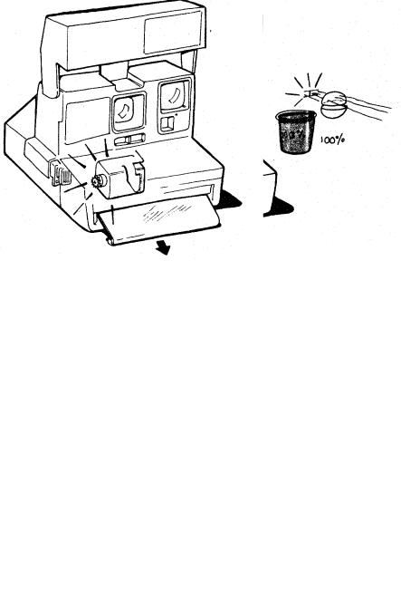
7.When the photocell sees 100% of the light needed for the exposure, the camera electronics orders the flash to quench and the solenoid to energize. The solenoid then pulls the blades closed.
8.After the blades close, the motor is turned on, activating a gear drive system similar to the system in the OneStep. The timing gear:
advances the pick indexes the counter
brings the S5 actuator back to its original position.
The solenoid deenergizes and the shutter system is again latched closed, ending the fillflash sequence.
6

9.The sequence for low-ambient conditions begins identically to the fill-flash sequence. The flash is charged via S10 and the shutter blades open the same way. However, the flash is fired by the internal clock reaching 74 ms, rather than by the photocell light measurement. This happens because there is relatively little light passing through to the photocell.
10.Next, the camera logic asks whether the subject is NEAR or FAR. This information is needed to properly set the electronics for low ambient pictures.
7
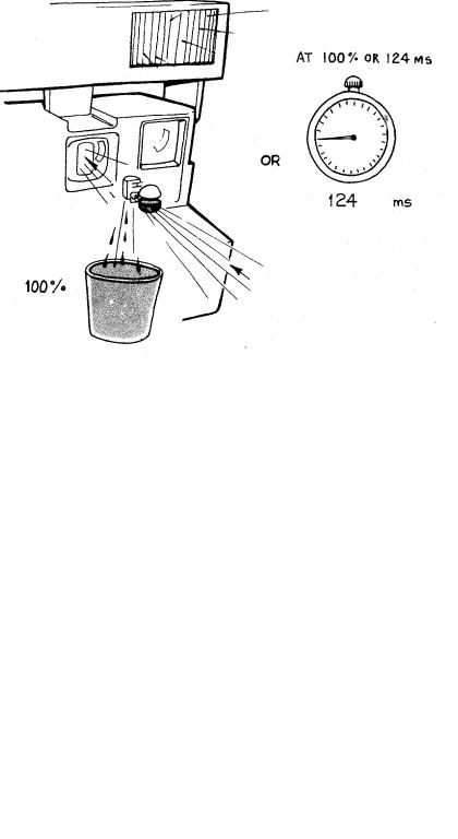
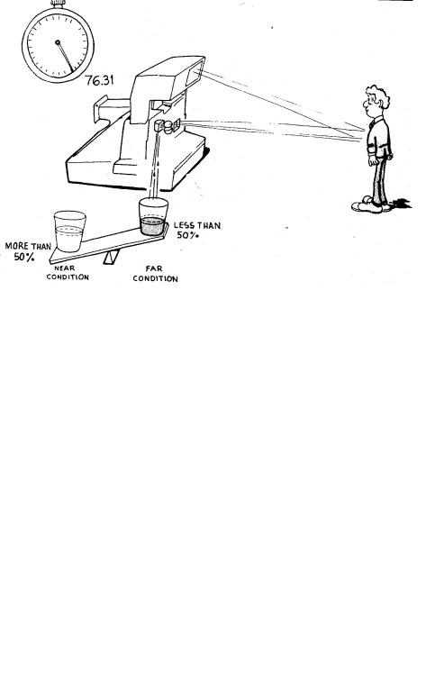
11.The camera determines whether the subject is NEAR or FAR by measuring the amount of light reflected back to the photocell 2 milliseconds after the flash has fired (76 ms into the exposure sequence). If the measurement is more than 50% of the total needed for a proper exposure, the camera decides the subject is NEAR. If the subject is NEAR, the electronics sets the clock to time-out at 124 ms.
12.In a low-light NEAR picture, the blades open partially so that the photocell is measuring infrared light through the infrared filter. The flash is quenched and the shutter blades closed either when the photocell sees 100% of the light needed for a proper exposure or when the internal clock reaches 124 ms.
8
13.After the blades close, the motor is turned on. The timing gear advances the pick, indexes the counter, and brings the S5 actuator back to its original position. The shutter system is latched closed, ending the low ambient NEAR sequence.
14.If the light measured 2 milliseconds after the flash has fired is less than 50% of the total needed for a proper exposure, the camera decides the subject is FAR.
9

15.In a low-light FAR picture, the blades open fully and the photocell sees scene light through the photopic filter. When 100% of the necessary light is seen or when the internal clock reaches 396 ms, the flash is quenched and the shutter blades close.
16.After the blades close, the motor is turned on. The timing gear advances the pick, indexes the counter, and brings the S5 actuator back to its original position. The shutter system is latched closed, ending the low-ambient FAR sequence.
10
17.For a non-flash picture (through a window), the exposure is started by pressing S1 only. The end-exposure command is given either when the photocell sees 100% of the necessary light for a proper exposure or when the internal clock reaches 396 ms.
11

Camera Operating/Exposure Sequence Diagram
12

SECTION 3 - MODEL 636 THEORY OF OPERATION
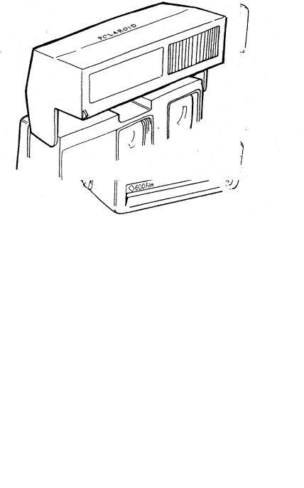
1.This is the Model 636 Camera which is one of a new line of 600 cameras.
2. The Model 636 shares many of the features of the 635 and 640 Cameras. Among these are: Fixed Focus Lens, Electronic Shutter, Film Shade, Lighten/Darken Control, Empty Pack Lockout, Film Counter, Carrying Strap and a Fill Flash Capability.
13

3.One of the major differences between the Model 636 and the OneStep is the type of film it uses. Like all of the 600 line, the 636 uses a new film format. The film has a speed of 6O0 ASA.
4.On the inner edge of the 600 film pack is a set of molded plastic tabs which interface with the pack spring in the camera. The two middle tabs press down the ramps of the pack spring, allowing the film pack to slide over the stop for insertion into the camera. On older style SX-70 packs there are no tabs. As a result, the pack is prevented from being inserted into a 600 line camera by the pack spring stop.
14
5.On the other hand, a 600 film pack cannot be inserted into an SX-70 style camera since the tabs on the pack are held back by the older style pack springs.
6.The battery in the 600 film pack has a higher capacity than the conventional SX-70 battery. It provides power for the shutter solenoid, the motor and for the built-in electronic flash.
15
7.When you open the camera, you can see another obvious difference between the Model 636 and the One Step — a built-in electronic flash. The flash is designed to be used for all pictures, both indoors and outdoors.
8.The electronic flash features a rapid charge time of about 5 seconds. For outdoor pictures, the flash is used to provide a proportional fill-flash to eliminate objectionable shadows. Indoors, the flash provides controlled light for scenes within a 4 to 10-foot range.
16

9.The flash is charged by lightly pressing the camera exposure button. The exposure mode is electronically inhibited until the flash is fully charged. When the green LED comes on, a picture can be taken by pressing the exposure button in all the way.
10.An alternate way to charge the flash is to lightly press the exposure button. The button can then be released. After the green LED has come on the flash will stay fully charged for approximately one minute. When the exposure is ready to be made, the exposure button is pressed in fully, in one motion.
17
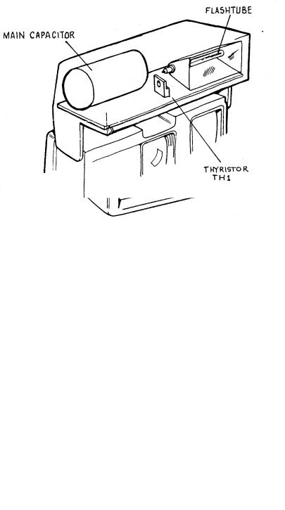
11.The built-in flash is an electronic quench-type flash. It can provide a full output of about 340 zonal-lumen seconds (ZLS) to illuminate a scene or it can be shut down early to provide less light to the scene. The way the camera decides to provide full or partial light output will be discussed later.
12.Whether or not the flash provides full output, the main capacitor delivers the same amount of energy. Therefore, if the flash is ordered to shut down early, some means must be found to dissipate the remaining energy in the circuit. This remaining energy is diverted through a thyristor (TH1) on the strobe board.
18

13.Now, let’s talk about the way the camera logic decides when to fire the flash and how much light it needs from the flash before it quenches it.
14.Refer to the Sequence of Operation section for a description of the order in which all of the events in an exposure cycle occur. (The operating sequence is also shown in diagram form, at the end of Section 2.)
19

15.There are three different conditions in which a flash picture can be taken:
1 - In high ambient light.
2 - In low ambient light with the subject near the camera.
3 - In low ambient light with the subject far from the camera.
16.Basically, the Model 636 uses either a light measurement alone to fire and shut down the flash, or a combination of light measurement and time measurement to fire and shut down the flash. The method used depends upon scene brightness.
20
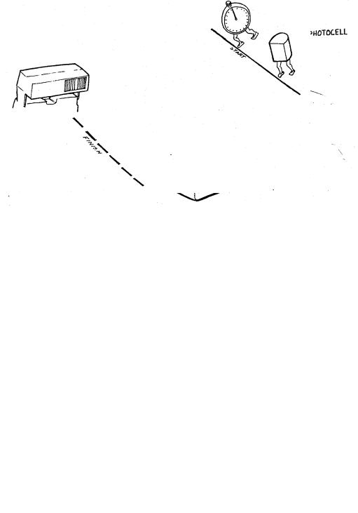
17.After the flash is charged and the exposure button is pressed all the way in, three things happen simultaneously which decide how the flash is going to be controlled:
1 - The solenoid releases the shutter blades and they start to open; 2 - The photocell starts to measure scene light;
3 - An internal clock in the camera logic is started.
18.From this point, there is a race between the internal clock and the photocell to decide which is going to control the flash. Either the internal clock will time-out before the photocell measures a pre-determined amount of light or vice versa. Whichever occurs first will fire the flash.
21

19.Now, let’s go back to the three conditions in which a flash picture can be taken. The first is in high ambient light. In this condition, there is so much scene light available that the photocell always wins the race to fire the flash. This is the Fill Flash mode of operation.
20.In the high ambient or Fill Flash mode, the photocell measures scene light. When it sees 75% of the total light required for a proper exposure, the photocell fires the flash.
22

21.At this point, the blades are still open and the exposure is being made. The photocell continues measuring light which now includes the light bouncing back from the flash. Next, the camera must decide when to shut down the flash and when to close the shutter blades.
22.In the high ambient (Fill Flash) mode, the photocell makes the decision to shut down the flash and close the shutter blades. It does this when it sees the remaining 25% of the light required for a proper exposure. (This light is provided by the flash.) The camera logic signals the flash to quench and commands the solenoid to close the blades.
23
23.The next condition in which a flash exposure can be made is in a low ambient condition (low light level, outdoor scenes and all indoor scenes). In this condition, there is so little light that the clock beats the photocell in the race to fire the flash. When the clock reaches 74 milliseconds (ms), the flash is fired.
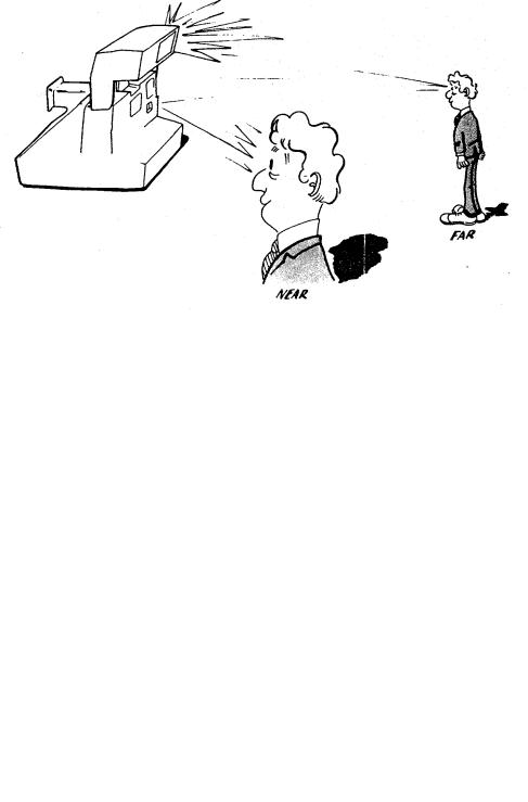
24.Two milliseconds after flash fire, a very important question is asked by the camera logic: Is the subject near or far? The answer is needed to properly set the clock for time-out.
24
Loading...