


100 Series
Polaroid 100 Series, 300 Series, 200 Series, 250, 360 Repair Manual
...
REPAIR
MANUAL
100 - 200 -
300
SERI
ES
AUTOMATIC
PACK
LAND
CAMERA
MARCH 1970
I
...
IMPORTANT
:
The Guarantee
does
not cover cameras which have been tampered with, modified for special
purposes
,
or repair
ed
by any person
or
shop
oth
er
than
an approved Potaroid repair station.
P
OLAROIO COR
PORATION I CAMERA PROOUCTS
SER
VICES I WALTHAM , MASSACHUSETTS

-
TABLE
OF CONTENTS
Title
Page
Section I .
Introduction
. . , . .
I
Section
II
. Princip'es of
Operation.
2
The
Film
P(lCk
, . , 2
-
The Spread System . . .
3
The Focusing System . . 4
-
-
Lenses,
. . . . . . . . 4
RangefioderslViewfinders
5
Image
Sizer . . . . .
5
Potaroid Rangefinder/Viewfinder
6
-
Zeiss
Ikon Rangefinder/Viewfinder
7
Timers • • , . . ,
8
Mechanical T
im.r.
, . ,
8
Electronic Timer . . • .
9
Flashgun . . . . . . . .
10
Section
III
" Camera Checkout
13
Vjsual Inspection . . . . . . • .
13
Checking Shutter Battery Voltage • 15
-
Checking
the
Shutter
Interlock . . ,
15
Checking
the
Shutter
Release
Burton.
15
-
Measuring Timer Acturacy , • , . . , . •
15
Measuring Timer Battery Voltage and Current Drain 16
Tjmer Switch Continuity
Check,
• . . . . , , . . . . ,
16
Checking
the
Lens and Rangefinder/Viewfinder (Collimation) 16
-
Rangefinder/Viewfinder Parallax Check.
18
Image Sfzer Parallax
Check,
. . 19
Bellows Light
leak
Test . . . .
19
Flashgun Testing ,
.. , •..
19
-
-
-
-
Section
IV
- Troubleshooting ChartS 21
Problems Evidenced in Pictures
21
Electronic
Timers,
. , "
25
Mechanical Timers
27
Spread
System
. . . , .
29
Rangefinder/Viewfinders .
31
Miscellaneous . , . . .
33
Model
268
Flashgun.
. .
35
Section V . Repairs and
Adjustments.
. , , . . . , ,
,.
.,.
37
-
Conversion
of
Pack Cameras with Serial Numbers starting with
"AA"
37
Serial
Number
Transfer. . , . . . .
38
Rear
Door
{Back
Cover) Replacement
38
Exit
Door
Replacement , . . ,
38
Slide Block
Replacement.
. . ,
39
Spread Roll Spring Replacement
40
Shutter
Housing Replacement
42
Bellows.
Replacement . . . • 44
-
Front
Lens
Reptacement,
. . .
46
Rear
lens
Replacement . . . .
48
-
Lens Bezel Replacement . . . .
50
Flash Filter
and
Cell
Wedge
Replacement.
50

TABLE
OF
CONTENTS (continued)
Trt~
P~
PhotOCi!tI
Lens
Replacement
51
Focus
Bar Replacement . . 51
Inner Frame (Top) Replacement 52
Inner Frame (Bottom) Replacement 53
U·
Frame Assembly R eptacement . 53
Shutter
Release Cabje Replacement
and
Adjustment
of
Retease
Button
54
Battery
I nterlock Replacement . . . . . . . .
55
Adjusting
the
Battery I nterlock
Switch.
. • • •
56
Battery
C_e
and Left Hand Guard Replacement
56
Battery
Terminal Replacement , • . . . . • .
58
Mechanical Timer Replacement . . . . . • • . 59
Replacing
the
Electronic Timer
.•
, . . •
..
.
60
Replacement of Non-Folding Rangefinder/Viewfinders . .
6J
Pictorial1ndttx &
Common
Hardware -
1001200
Series
Viewfinder
Assembly,
1001200 Series
Rangefinder/Viewfinder
Assembly·
1001200 Series
Rear
Door
& Rear Cover
Auembty -100/200
Series
Body Assembly & Bellows· 1001200 Seri
..
Shutter
Assembly·
l00/2005eri
..
Front
CCNer
Assembly·
100/200 Series
Pictorial Index
&
Common
Hardware -
300
Series
Viewfinder
Assembly·
300
Series
RangefinderNiewfinder Assembiy -
300
Series
Rear Door
& Rear Cover Assembly -
300
Series
Body Bellows Assembly -
300
Series
Shutter
Assembly.
300
Series
Front
Cover
Assembly·
300
Series
Electronic Timer
Switch
Continuity Check
&:
Adjustment.
62
Electronic Timer
Switch
Replacement • . • . , • .
63
Replacement of I
mage
Sizers . • . • • . . . . • . . .
63
Replacement
of
Folding RangefinderNiewfinders , . . • 64
Replacement
of
Polaroid
RFNF
Optics Assembty & VF WindOw.
64
Replacement of
Folding
RFIVF Magnet . • . . •
..
..•
65
Replacement of Folding R F IV F Pivot Pads . . • • . . . . . •
66
Rangefinder/Viewfinder and Image Sizer Adjustments: • . . . .
58
lens
Col1imation . . . . . . . . . . • • . • . , . . • . , • .
71
Replacement
of
Cantilev-er Assemblies
and
Housings
in
Polaroid
RF/V
F 72
Repair
of
the I
mage
Siz.er. . . . . . • . . . • . " • • . • . . .
73
Conversion
of
4,5NOC
Flashguns
and
Replacement
of
Old
Battery
Clip$
74
Section VI . Parts
Identification,
. . . . . _ . • . . , . • . , • . .
75
-
-
-
-
-
-
-
-
-
-
-
-
-
-
-
-
-
-
Figure
2-1
Figure
2·2
Figure
2~3
Figure
24
Figure 2·5
Figure
2-6
Figure 2-7
Figure 2·8
Figure 2·9
Figure 2·10
Figure
2~
11
Figure
2·12
Figure
2·13
Figure 2·14
Figure 2·15
Figure 2·16
Figure 2·17
Figure
3..1
Figure
3·2
Figure
3-3
Figure
3-4
Figure
J...5
Figure 3-6
Figure 3-7
Figure
3-8
Figure 3·9
Figure
3·10
Figure 3·11
Figure
3·12
Figure 3-13
Figure 3-14
Figure
5-1
Figure 5-2
Figure 5-3
Figure 5-4
Figure
5-5
Figure 5-6
Figure
S.7
Figure
5·8
Figure
5-9
FigureS-10
Figure 5-11
Figure
5·12
Figure 5-13
figure
5-14
Figure 5-15
LIST
OF
ILLUSTRATIONS
Title
Page
Pack
Loaded
in Camera .
2
White
Tab
Being
Pulled
. 2
Yellow Tab Being Pulled 2
View
of
Rear
Door
Components 3
Film
Being PUlled
Through
the
Rollers
3
FOCUSing
Components
..
,..
4
Image
Sizer Internal Configuration
..
5
Polarom Rangefinder/Viewfinder Internal
Conftgufation
.
6
Zeiss Ikon RangefinderNiewftnder I mernal Configuration 1
Mechanical
Timer
..
•...•
_.
.
8
Interna! Configur.atlon of the
Mechanicaf
Timer. 9
Sening of
the
Timing Ring
9
Electronic
Timer.
. , .
9
Electronic Timer Schematic • 10
Flashgun.
••.
11
Fla$hgun
Circuit.
..
.•
11
Reftector Positions . . 12
Shutter
Release
Button
Check
15
Timer
Battery Current Drain Test. 16
Camera
Mounted
on
Collimator.
16
Infinity
Tube Target .
,.
•.
17
Four
Foot
Target
••...••
11
Frame Target -
180
Ctose..up, • 18
Frame
Target·
180
Infinity &
l80Til.
18
FrameTarget-l00Closeup&
100 Tilt
18
Frame
Target. 100 Infinity &
100
Tilt 18
Camera
Mounted
on
Collimator
. . • 19
F
rams
Target • 100 Closeup & lOOT
ilt
19
Flashgun
Identification..
.
19
Universal Fla$hgun Tester
...
20
Fla$hgun
Battery
Speciftcation.
20
Removing
the
Exit
Door
..
38
Installing
the
Exit
Door
...
39
1"""lIing
the
SI;';" Block Spring
39
Replacing
the
Edge
Control
Bar 40
Removing
the Rear
Rolf, . • •
40
Removing
the
Front
Roll.
.
41
Remo.ving
the
Spread
Roll Spring
41
Removing
the
Bellows Fasteners
43
Installing New Fasteners
Preparing
the Drill ,
..
Drilling
Out
the
Post.
,
Prying
the
Betlows
Tabs.
Installing
the
Benows.
43
• 44
. . .
45
• . .
45
..
46
Removing
the
Front
Lens- Metal
Shutter
Housing
46
Removing
the
Front
lens
- Plastic
Shutter
Housing
41
LIST OF ILLUSTRATIONS (continuedl
Figure 5-16
Figure 5-17
Figure5-18
Figure 5-19
Figure 5-20
Figure 5-21
Figure 5-22
Figure 5-23
Figure 5-24
Figure 5-25
Figure 5-26
Figure 5-27
Figure 5-28
Figure
5-:19
Figure
5-30
Figure 5-31
Figure 5-32
Figure 5-33
Figure 5-34
Figure 5-35
Figure 5-36
Figure 5-37
Figure 5-38
Figure 5·39
Figure 5-40
Figure 5-41
Figure 5-42
Figure
5·43
Figure &44
Figure 5-45
Figure 5-46
Figure 5-47
Figure
5·48
Figure 5-49
Figure
5·50
Figure 5·51
Figure 5-52
Figure
5·53
Figure &54
Figure 5-55
Figure 5-56
Figure
5·
57
Figure 5-58
Figure
5·59
Title
Page
Removing Lens Retainer,
•••....••
47
Identifying
the
Rear Lens . . • . . , . . .
48
Removing Rear
lens-
Metal
Shuner
Hauling.
49
Removing Rear
lens·
PlastIc
Shunel'
Housing.
49
Identifying the
Front
LaM
..•
, . , .
50
Removing
the
Focus Bar
and
Inner Frame
51
Removing the
Bottom
Inner Frame 53
Driving
Out
the
Cable Housing . , . . 54
Driving
Out
the
Bushing
••••...
54
Crimping
the
Shutter
Release
Tip.
. .
55
Adjusting the Battery Interlock Switch.
56
Freeing
the
Battery Cradle
..•
56
Removing
the
lett
Hand
Guard.
57
Installing the
Left
Hand Guard •
57
Replacing Battery Terminal
..
58
Removing
the
Mechanical Timer.
59
Installing
the
Timer
..•..•
59
Forcing
Out
the
Index Plate
.•
60
Removing
the
Driving Knob
•.
60
Freeing
the
Electrical Nameplate 61
location
of
Timer
leads
..
61
Unsoldering
the
Switch Leads . 61
Installing
the
New Knob
..•.
62
Checking
the
Timer Switch
.•
,
63
Checking
the
Switch Under
load
63
Positioning
the
R F
IV
F on
the
Camera .
63
Freeing the
RFIYF
• . • . . .
64
Installing a Foldlng RFtVF
•. , ...
64
Removing
the
OptIcs
Assembly.
. . .
64
Driving
Out
the
Magnet Pivot
.•...
65
Range/Topside AdjU1tments
for
Zeiss Ikon
RFtVF.
66
AangefTopside Adjustments for Polaroid RF/VF
.•
67
Range
Adjustment
for Image Sizer
..
, • , . , .
68
Parallax Horizontal Ad;ustment for Zeiss Ikon RF/VF
68
Parallax Vertical Adjustment
for
Zeiss
~kon
RFtVF
69
Parallax Adiustments for Polaroid
RFNF,
70
Camera Mounted
on
Collimator
...
71
Removing
the
lens
Mount.
, . . .
71
Freeing
the
Front
Element.
, . . ,
71
Removal
of
the
Cantilever Assembly.
72
Identifying
the
RFNF
Model. .
..
72
Cu t the
Locating
Pin.
....,
73
Aligning
the
Cantilever Assembly and Housing.
73
Centering
the
F iller Pad
...•.....
74

78
-
-
LIST
OF
ILLUSTRATIONS
(eontinuedl
-
Title
Page
Pictorial Index
&
Common
Hardware·
1001200 Series
Viewfinder
Assembly
- 100/200
Series
-
RangefinderNiewfinder
A""""bly -100/200
Series
Rear Door & Rear Cover Assembly· t
00/200
Series
Body
Assembly &
Bellows·
100/200
Series
Shutter
Assembly
-1001200Series
Front
Cover Assembly - 1001200
Series
Pictorial lndex &
Common
Hardware·
300
Series
-
Viewfinder Assambly -
300
Seri
..
RangefinderlViewfinder
Assembly·
300
Sel'ies
Rear Door & Rear Cover Assembly·
300
Series
Body Bellows Assembly - 300
Series
Shutter
Assembly -
300
Series
Front
Cowr
Assembly -
300
Series
-
-
-
-
-
-
-
-
-


-
-
-
-
SECTION
I - INTRODUCTION
-
nlis
manuai provides repair information
On
the
-
-
optic and mechanical components
of
all auto-
matic pack came"i$ jn tbe
100,200.
and
300
linc'.>.
This manual, coupJed with the
two
manuals
referenced below,
should
proVide
aU
the
informa-
tion needed
to
repair any
of
the following
camenl:S;
100
Lin~
200
Line:
300 Line
100 250 360
101
240 350
102
230
340
IOJ.
225
335
104 220
330
125
215 320
135
210
315
- Repair information
on
automatic shutters used in
the
pack cameraS
may
be
found in the
"Repair
Manual
on
Model
362,
366. and 374 Automatic
Shutters"
and
in
the
"Repair Manual
on
the
-
ModeJ
360
Camera."
(In
addition.
the
latter
manual
COVers
repair procedures
On
the
electrOnic
-
flash, battery charger, and
other
items peculiar
to
that
particuJar modeL)"
This
repair manual
IS
structured
as
rouows:
Section 1 is
the
introduction.
-
-
-
,.
These:
llUll'l\udl
ace
available
only
to
authorized
Polaroid repair stalions,
Section
JJ
contains the principles
of
operation for
the
film
pack, spread system. focusing s),slem.
lenses, range finder/viewfinders, flashgun, and
timers.
Section
III
presents a detailed visual checkout
procedure
which should be done for
<.I
stock
or
"re~do"
Camera brought
in
for repair. Also
in~
eluded in the section are test,ng procedures designed
to
verify proper operation
of
the
shutter
battery, shutter interlock, shutter release
button,
bellows, lenses, rangefinder/v}ewfinders, and timers.
Section
IV
is a compilation
of
trou
bJeshooting
charts, These charts
list problems associated
with
pack cameras. their possible causes, and the
sug~
gested solutions.
Section
V details the procedures to folJow when
adjusting or replacing any
component
of
the automatic pack camera_ Repair personnel are cautioned
to
note
the
differen4."CS
among models
when seJecting
these procedures.
Section
VI
is
the
parts identification section,
It
contains parts lists and exploded view drawings
for
aU
100>
200, and 300
Hne
cameras.
SECTION
II -PRINCIPLES
OF
OPERATION
THE
FILM PACK
A
d~:o.t:ripfion
of
the
Polaroid Land
pack
I..'ilmera
~hould
beltin with an explanation
of
the operation
of
tht>
film p:u;k itself.
The
following description
1s
Olpplk:able
to
both
the
black and white
(Type
107) lind
rhe
color
(Type
t08)
film
pack.
Figure
2~1
is a cross-sectional representation
of
a
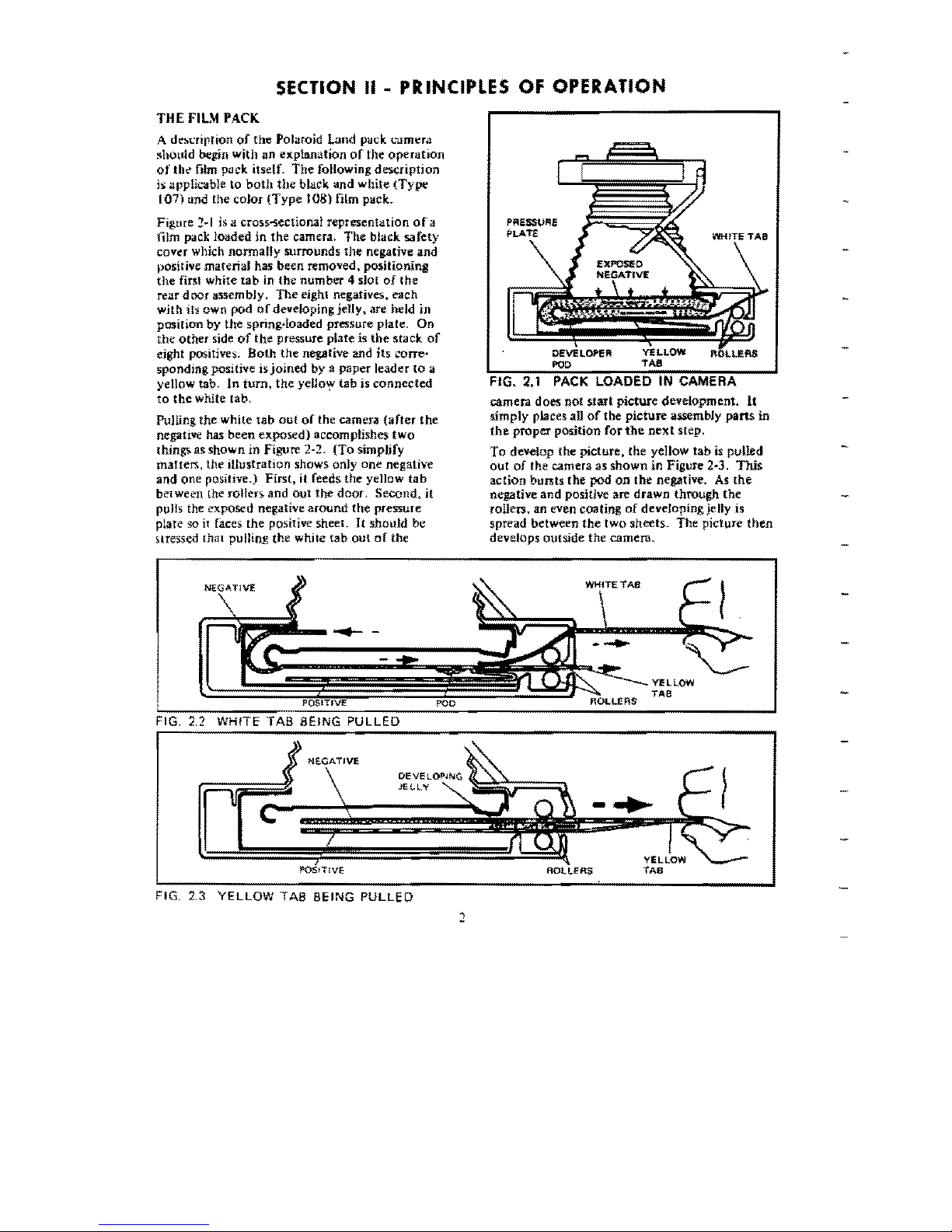
film pack looded in the camera.
The
black
safety
cover which normally surrounds
the
negative and
positive
material
has
been
removed.
positioning
the
first white
tab
in the number 4 slot
of
the
rear door assembly.
The
ejghl negatives. each
with
its
own
pod ofdeveloping
jelly.
are
held in
posifion
by
the
spring~loaded
pressure plate. On
the
other side
of
the
pressure plate is
the
stack
of
eight positives.
Both
the
negative and its corre-
sponding
positive is
joined
by a
paper
leader
to.
it
yellow
tab,
In
turn,
the
yeUo'>;V
tab
is
cennected
to
the
white
tab.
Pulling
the
white
tab
out
ef
the
camera
(after
the
negative has
been
expos,ed)
accomplishes
two
thjn~
as
shown
in
Figure
2~2.
(To.
simplify
matters,
the
illustration
shows
only
one
negative
and
one
positive.)
First,
it feeds
the
yellow
tab
be1ween
the
rollers.
and
out
the
door.
Second.
it
pulls
the
exposed
negative
around
the
pressure
plate
50
it
faces.
the
positive sheer.
It
should
be
~lTesscrl
thal
pulling
the
white
tab
out
of
the
POD
TAB
FIG.
2.1
PACK
LOADED
IN
CAMERA
camera
does
not
start
picture
development.
It
simply
places
aU
of
the
picture
assembJy
pans
in
the
proper
position
for
the
next
step.
To
develop
the
picture,
the
yellow
tab
is
pulled
out
ef
the
camera
as
shown
in
Figure
2-3.
This
action
bursts
the
pod
on
tbe
negative. As
the
negative
and
positive are
drawn
through
the
rollers.,
an
even
coating
of
deveIopingjelly
is
spread
between
the
two.
sheets-
The
picture
then
develeps
outside
the
camera.
-.-
--
-
TAB
YEllOW
FIG. 2.2
WHITE
TAB
BEING
PULLED
JE('lY
-
..
ROtJ
...
EAS
FIG. 2.3
YELLOW
TAB
BEING
PULLED
THE
SPREAD
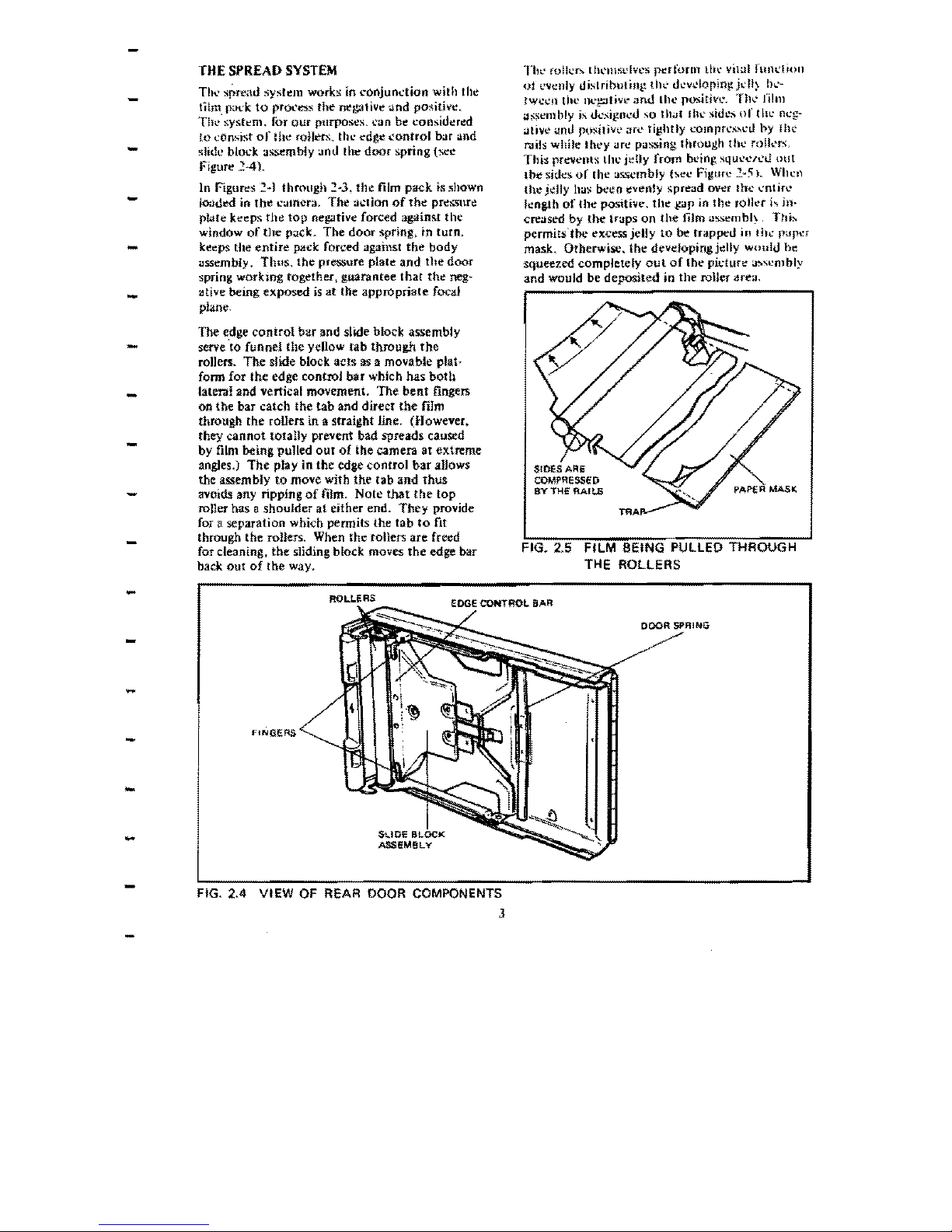
SYSTEM
Thl'
(Oller:..
lhl'IllSl'lvcs
p~rfonll
till'
ViI
"I
fUlll"!
iOI1
Till.'
spre,uJ
sysh~111
works
in
coojundioo
with
the
-
lilm pat:k
to
proct:$."
the
negative ilnd pO$itivc.
Thl."syskm.
Ibr
our
purposes.
\,,'an
be
considered
to
~Onslst
of
the roilers. the edge
control
bar and
slide
blod
assembly
:.lor.!
the
door
~pring
(!>Cl"
-
Figure
::!4t
-
In
Figures
2~1
through
2~3.
the
film pat:k
IS
shown
I();hj~
in
the
camera. The
:H:tion
of
the
pressnrl;!
pwte
kc~ps
tht!
top
negative
forced
agai.nst
the
window
of
the
p<lck.
The door spring, to turn,
ket':ps
the
entire
pack forced against
the
body
-
-
Olssembly, Tlnls.
the
pressure
plate
and
the
door
spring workmg together, guarantee thar
the
neg-
Siitive
being
exposed
is
at
tbe
appropriate
focaJ
plane.
The edge
conlrol
bar and slide block assembly
serve 'to funnel
the
yellow tab through
the
-
rollers. The slide block acts
as
a
movable
plat-
fonn
for
the edge controJ bar whleh has
both
-
lateral
and
vertical
movement.
The
bent
fingers
on
the
bar
catch
the
tab
and
direct
the
film
through the roUefS
in
a
straight
Jine.
(However.
they cannot
fOtaUy
prevent
bad
spreads caused
-
by film being pulled
out
of
the
camera
at extreme
angles.)
The
play in the edge control
bar
aJJows
the
assembly
to
move
with
the
tab
and
thus
avoids
any ripping
of
mm,
Note
that
the
top
roner
has
a shoulder
at
either
end.
They
provide
for a
separation
which
pennits the
tab
to
fit
through the rollers. When the rollers
are
freed
-
for
cleaning,
the
sliding block
moves
the
edge
bar
back
out
of
the
way.
-
-
-
-
-
-
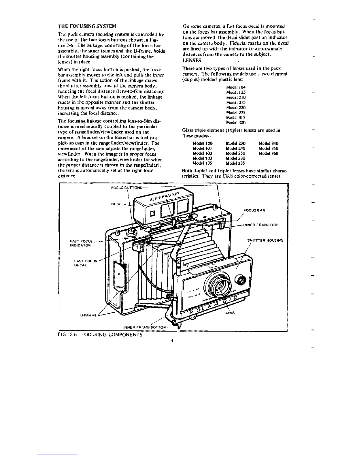
-
of
evenly
dislributill~
thl'
d~vcIQrin!!jdl)
hl'-
tween
the
ne~livt'
and
(he
positiv
....
Ill,,' film
.,:;scmbly is
dt.'~ignl'd
so
tllil' Ih\.'
",idl>:'
or
tin: neg-
ative
;.mrJ
posilive arl' tightly l'Ompn:ssl'rJ hy
lhl'
r.Jils
while
Ihey
"rc
passing
through
rhe
roll~'rs"
Thi:s
prevents
lill.'
jelly
from
bl'ing
SqUt.'t.'l'l'U
out
lbe
sides.
or
(he
:.I)L~mbly
hel'
Figure
'::~5).
When
th~
jeJly
ha:.;
been
i!v~nly
s.pre~d
over
!he ,,'ntirl'
lenglh
of
the
positive,
the
~ap
in
the
roll\'r
j.,.
in-
creased
by
the
tr"ps
on
the
film
.,ss~mbl~,
This
permits"t~
excess jelly
to
be
trapped in
Ih~
p<Jpt:f
mask.
Otherwisc.
the
deveJopingjelly
would
be
squeezed
completely
out
of
the
pic-tuft! a:>\l'mbly
and
would
be
deposited
in
the
roUcr "re;L
SIDES ARE
COMPRESSED
BY
THE RAILS
rnA
PAPER
MASK
FIG. 2.5
FILM
BEING
PULLEO THROUGH
THE ROLLERS
ROLLERS
eDGE CONTROL
8AR
FINGERS
DOOR
,*:"'00
FIG. 2.4
VI
EW
OF REAR DOOR COMPONENTS
J
THE
FOCUSING
SYSTEM
Tltl.'
I"ad
..
C~nler.!
focusing
system
is
controlled
by
the usc
of
the
two
focus
buttons
shown
in
Fig~
UTe
:-6.
The
Jinkage. consisting
ofltle
focus
bar
assembly.
the
inner frames and
the
U~frdme.
holds
Ih.:
shutler
housing assembly
(containing
the
lenses) in place.
When
the
right focus
button
tS
pushed~
the
focus
bar
assembly
moves
to
the
left
and
pulls the
inner
frame
with
j1.
The
action
of
the
Unkage dr4ws
the
shutter
assembly
toward
the
camera
body,
reducing
the
focal distance (lens-to-film diStance).
When
the
left focus
button
is
pushed,
tile Jinkage
reacts in
the
opposite
manner
and
the
shutter
housing is moved away from
the
camera
body,
increasing
the
focal distance.
The
focusing linkage controlling
lenNe-film
dis-
tance
is
mechanicany
coupled
to
the
particular
type
of
range finder/viewfinder used
on
the
L"'3mera,
A bracket
on
the
focus
bar
is
tied
to
a
pick~up
cam
in the range finder/viewfinder. The
movement
of
the cam adjusts
the
rangefinder/
viewfinder" When
the
image is in
proper
focus
according
to
the
rangefinderjviewfinder (or
when
the
proper
distance is shown in
the
rangefinder),
the
lens is
automatrcally
set
al
the
right foca!
distance.
On
some
cameras,
II
fasf focus
decal
is
mounted
on
the
Jocus
bar
assembly. When
the
focus
but~
Ions <lfC
moved.
the
decaJ slides past an
indicator
on
the
camera
body.
FiduciaJ
marks
on
the
decaJ
are
lined
up
with
the
indicator
to
lJpproximate
distances from the ClJrnera
to
the
subject.
LENSES
There
are
two
types
of
lenses used in
the
pack
camera.
The
following models use a
two
element
(duple!)
molded
plastic lens:
Model 104
Model'25
MOOeI210
Mod,I21S
Model
220
Model
225
Model
315
Model
320
Glass triple
element
(triplet)
lenses are used in
these models:
MooeilOO
Model
230
Model34Q
Model
HH
Model
240
Model
350
Model
102
Model
250
Model
360
ModeJ"I03
Model
330
Mode1135
Mod.lllS
Both
duplet
and
triplet Jenses have similar charac-
reristics,
They
are fjS.S
COloT-<':OrTected
lenses
RFfVF
FAS.T FOCU&
_-IfIf~::-::;;;;;
INOICATOR
FAST
FOCUS
DECAL
FOCUSING COMPON
FOCUS
8AR
FIG.
'2.6
4
•
•
•
-
with
ftko".tl
kngfll.'
or
J
1-1
l11i11imdcrs_
Al
f/ttt(
j
Ih~
~olor
~t!in.&).
!I\l' hypcrllH.:al
tlisl;lnc,,-"
i the
n
...'..
r
Hntit
of
the
sharp
fi~h.I
when
tht! c.lmer.i is
-
foeusa]
10
INFlNITY\
i~
42
ih:L
At
f;42
Uh~
bl'll:k and
whit~
st'llingi.
{he hypt'rfocal distan\.'e
tlrops
to
Mfect.
The
di3gonal fieW ofview is
55<>.
-
while tilt'
anguJ<lf
field
(;]t
INFINITY)
is
36<1
X
4t," .
RANGEFINDERS/VIEWFINDERS
-
111t'rc are
Ihrt~c
types
of
f.lIlgellnders/v1t'wfindefS
llscd in Polaroid
Land
aU[om;.atil: pack
cameras.
-
The first.
is
a relatively simple image
slZ!!r
which
frames the subject and provides a scale for
cstj~
mation
of
distance between e:.lmera and subject.
The
second model
is
a true
rangdinderJview~
nnder
which
focuses
by
superimposing
two
images
of
thl;' subject,
Separate
windows
are
pro~
vided for the focusing and
fmming
functions. The
-
-
third
type
js
the
Zeiss Ikon model which also
focuses
by
superimposing
two
images.
However.
both
the focusing
and
framing images are viewed
-
through a single
window.
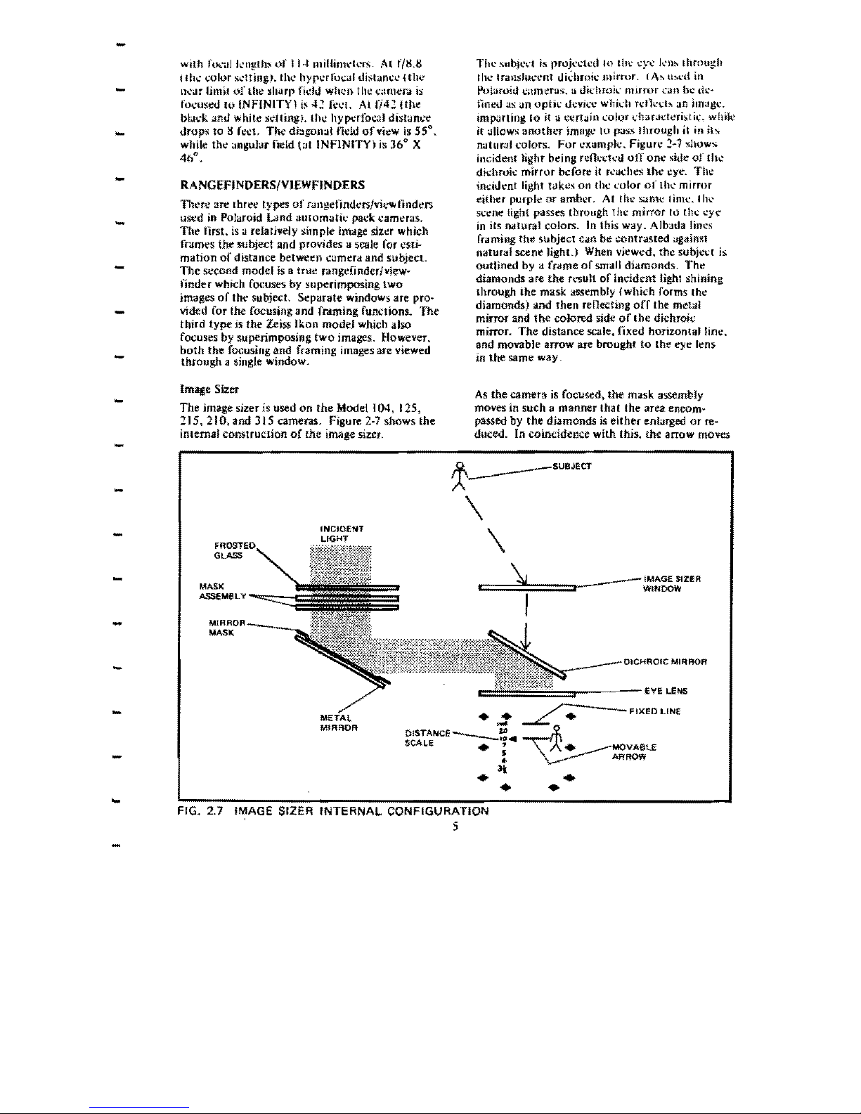
Image Sizer
-
The
jma.ge sizer is used
on
the
Model 104, 125.
115.
210,and
315 cameras. figure
2-7
shows the
internal construction
of
the image sizer.
-
-
INCIOENT
LIGHT
-
GLASS
-
MASK
ASSEMeL'I'
_""",-
-
MASK
-
-
MIRROR
T!J~
_'.;ubJt',:t
is
rroj~dl:l1lO
lIn:·
cyt' km. through
Ill
....
Irallsluc-t.'nt
lIi~hmk
mirror.
IA~
tbt"d
In
Polaroid c;lInt!ras:. a t1khmit"
nmror
can
bl:
dc-
tinetJ as
an
optil:
t1cvio."1:
whkh
rdl",·\:l:o.
an
im.,g~"
impJrting
10
it
a \:\.:rtOlin
color
dlarJct;..>ristit;. while
it allows
another
imllg;t'
to
pas.,
..
through
it
ill
ib
natural
",olon
•.
For
example.
Figure
2·7
show~
incident
light
being
rcOt't'lt'd
off
one
side
of [h....
dh.::hmit:
mirror
before
it
rt'Jt;hes
the
eye. Thl!
inddent
light
hikes:
on
tht!
t"olor
of Ih....
mirror
either
purple
or
amber.
At
the
lklnll.!
liml.!.lhl.'
scene light passes
through
the
mirror
10
till.!
eye
in
its
natural
colors.
In this
way.
Albada lines
framing
th~
subject
c.m
be
contrasted against
natural
scen~
light.)
When
vi~wed.
the
subjet't is
outlined
by a
(r"me
of
small diamonds.
Th~
diamonds
are
the
result
of
!nddent light shining
through
the
mask
ass~mbly
{whit:h forms the
diamonds) lind then
reOecting
off
(he metl'll
mirror
and
the
colored side
of
(he
dichroic
mirror.
The
distance scale.
fixed
horizontal
line.
and
movable
arrow
are
brought
to
the eye
I~ns
in the
same
way.
As
the camera
is
focused. the mask assembly
moves in such a
manner
tha t the area
el1com~
passed by the
diamonds
is
either
enlarged
or
re~
duced. In coincidence
with
this.
the
arrow moves
~
_____
SUBJECT
\
\
--===\;!!;===::>-
___
IMAGESIZER
L
t-
WINDOW
I
=::r-----Eve
LENS
•
~
~FIXEOLINE
=DISTANCE
____
....
~
SCALE
.'
•
MOVA8t£
S
ARROW
-
•
.
•
\
FIG. 2.7
IMAGE
SIZER INTERNAL CONFIGURATION
5
RIGHT
~~~~~~.(~t--W'G'\T"VEL'NS
r
!-.".fBI/!'
LENS
"\
<:
,
LEFT
:>
I
RANGEflNOEA
FlANG€FINDEA
WINOOW
WINOOW
8EAMSf>UrrER
y,
•
);ff-
ASSfM8k
y
H
7
R"
EY~E
MOVI>,BLE
WINDOW
~
IMAGE
I
I
FIXED
IMAGE
L
.J
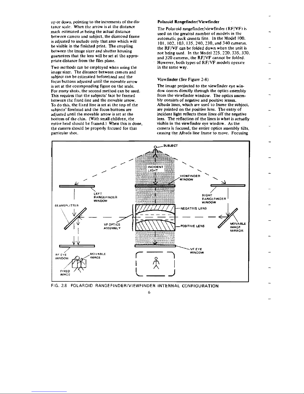
FIG. 2.8 POLAROID RANGEFINDERIVIEWFINDER
INTERNAL
CONFIGURATION
6
up
or
down. pointing
to
the
inC'rem~n(~
of
the
dis-
lilll~l"
sCilll",
Whl"n
thl"
OIrrow
is
<It
the distance
mark
l"Slim;Jll"d
as being the
actu<l1
distance
bl"tw!!!!n
L'Zlm!!rll
und subject. the
diamond
frJme
il'i
adjusted
to
indude
only
that
area which will
be visible
in
the finished print. The .coupling
bdween
the image sileT and
shutter
housing
gu.mmtees
that
the lens will be set
at
the
appro--
prialedistance
from
the
film piane.
Two
methods
can
be
employed
when using
the
image sizer.
The
distance
between cam!!r3
and
subject can
be
estimated beforehand
and
the
focus
buttons
adjusted
until
the
movable
arrow
is set
at
the corresponding
figure
on
the
scale.
For
many
shots.
the
second
method
can
be
used,
This requires
that
the
subjects'
face
be
framed
between the fixed line
and
the movable arrow.
To
do
this. the fixed line is set
a1
the
lop
of
the
subjec1s' forehead
and
the focus
burtons
are
adjusted untH the movable arrow is set
at
the
boHom
of
th~
chin. (W.th sman
children,
the
enlire head should
be
framed.) When
this
is
done,
the
camera should
be
properly
focused for
thai
parricular
shOL
Polaroid Ran.sefinder/Viewfinder
The
Polaroid rJngefinder/viewfinder
jRF/VF)
b
used
on
the
greatest
number
of
models
in
the
<It1tomatk
paL'k
carner
.. fine. In the Model 100.
101, 102, 103, 135, 240, 230, and
340
cameras,
the
RF/VF
can
be
folded
down
when
the
unit
is
not
being
used. In
the
Model
225.
220,
335.
330,
and
320
cameras, the
RF/VF
cannot
be folded.
Howc¥er,
both
types
of
RF/VF
models
operate
in
the
same
way.
Viewfinder (See Figure
2--8)
The
image projected
to
the
viewfinder
eye
win-
dow
comes
directly
through
the
optics assembly
from
the viewfinder window, The
optics
assem-
bly consists
of
negative
and
positive lenses.
Albada
iines~
wttich are
used
to
frame
the
subject.
are
painted
on
tbe
positive lens,
The
entry
of
incident
light reflects these
Jines
off
the
negatjve
lens,
The
ret1ection
of
the
lines is
what
is actually
visible
in
the
viewfinder eye window.
As
the
camera is focused. the
entire
optics
assembly tilts,
causing
th_e
Albada line frame
to
move. Focusing
OOJECTIVE
cENS
I,
MASK
ASSEMBLY
MOVAlILElMAGE
APEATURE PLATE
IMAGE
UNS
-
from
I~FJNITY
tv
ClOSE-UI)
..
for
t'xampll.',
<111
upcnin!,! in
fhl'
opl
ie"
;'1~"'l'ml;l)
.1I1d
1\
~nlk\.'"
mnv,,'S
the
ff'JIUI.'
uownw;Jrt.L
tfm
,,'''[feme
thlt.'
ix'amsplilllt.'r
whkh
rc\!,,'(s,,'S
It
:J~Wln.
Fmm
-
ltOSE~UP
shots.
iI
is
lil'\.·t'S.\;I(Y
to
allow
ii
liltJ,:
(he
tn.'<.lmsplincr.
thc
imag,,'
b:
(dk',:h:lI
to
llw
l'Xfr,J
~pa~e
between
tltt.'
SUQjl'ct
nnd
the
top
r<.lnp:cfinder
eye winllow.
. F!G. 2.9 ZEISS IKON RANGEF!NOERN!EWF!NOER
INTERNAL
CONFIGURATION
7
-
-
-
-
-
-
-
-
-
-
-
-
-
-
-
-
-
(rame line
beC;lU,\C
the
optics
aJo>-'>embly
\,,',lnoot
tilt t!nough
to
comrenS<lt~
properly.)
R:mgefinder
When looking: through the rangefmder eye window
(when the camera is
out
of
focus). two images are
seen in the small
amber
or purple square. (In some
cameras. this may
be
a circie.) These images resull
from the ability
of
the bearnsr!itter
to
have iight
transmitted through
il
while simultaneouslY hav-
ing light reflected from it. This
pro
pert)' aUows
the viewer
to
observe one image superimposed
upon .mother image.
The
bearnspHtter also has
dichroic characteristics which
impart
color
to
the
reOected
image. One
of
these jmages.,
the
fixed
jma~,
comes directly from the left rangefinder
window and is
transmitted
through
the beam*
splitter
to
the
eye
window.
The
second image;
the movable image. is channeled
through
the right
rangefinder window
to
the movable image
mirror
which reverses it.
The
image is reflected through
BEAMSPUTTliiR
EYE LENS
IMAGE II
r~¢:l
L
MOVABLE
__
J I
IMAGE
Fo.:usmg the
l'a
me
r.l
jlivut~
the Olo\':Jhk
m\a~
..
'
mirror
through a small arc. This
mOVl'm~nt
..
hift'>
the
ima,g.e
left
or
rigllt
on
the
hcam\\J1lill~r.
Wlh.'tI
tht!'
moV".!Me
image
m"'rl:!l'~
with
tile'
fixltu im;;;tl'.
the
I".'amerd
i:i
properly
focusell"
Zeiss
Ikon
Rangefinder/Vrewfindcr
The
Zeiss Ikon r.mgefinderivicwtlnucr
i..,
a
\ingk
window.
projected
frame.
superimrH)lIl".-U
imJ,jl'..·
finder.
II
is
used
on
the
Model
~50.
350.
;100
3(,0
came(:Js,
Viewfinder
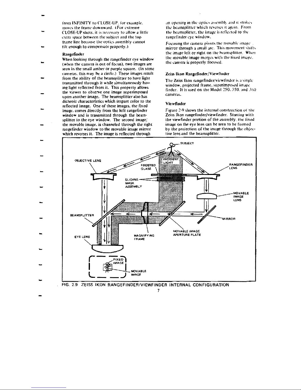
Figure 2-9 shows
the
internal con:.aruction
of
lhe
Zeiss Jkon r.!ngefinder/viewfinder. Slanln!!, with
the
viewfinder
portion
of
the
as.
...
~ml>ly,
fhe
nx~tl
image
on
the
eye
lens
can
be
seen
to
be
formed
by
the
projection
of
the
image through
the
objt.'i.'*
live lens and
the
beamspliuer.
T1lt.'
Alhuda
hne
ttht:
dout'u
amber
lint'
which
fr;tmt:~
tht: fixed image) results from
ioddent
light fXIltiinfl.
through
the
frosted glass
and
the
sliding: mask assembly.
The
as!i.embly l'Onststs
of
two
masks linked
together
and
tied 10 the
1'O("us-
ing bar.
As
the
camerJ
i~
focused from
infinity
10
close-up,
the
sliding mask moves
~lDd
cau~
the
Albada line
to
rontrdcl,
I.:ompensating for
the reduced image area.
The
inddent
light
pro-
jects
the
Albada line
to
the movuble image
aper·
ture
plate
and
it
is
then
renel'led
through
the
magnifying
frame
to
the
beamsplitter.
The
dichroic
characteristic
of
Iht
beamspliner
gives
the
Albada
Hnt
its amber coJor as
if
passes it
10
the
eye lens,
Rangefiilder
Simultaneous
with
the
projection
of
the
image
through
the
objective
lens, is
the
projection
of
the
image
through
the
rangefmder
Jens. Where
the
image from
the
objective lens is a rea) fixed
image.
the
image
coming
from-fhe range-finder
lens differs
in
that
it
is
movable from
left
to
right.
The
rangefindtf
image is
sent
to
the
eye
lens
as
follows:
I.
The
rangefinder lens
and
the
movable
image
lens invert the image
and
pass it
through
the
mnror .
..,
The
mirror
reverses
the
image and
projects
it
through
the
opening
in the movabJe image
apeflilre pJ:J!t'
to
the
center
of
the
magnifying
frume.
~~
Passmg
through
the
center
of
the
magnifying
lrume,
the
image is
mverted
:Jgain
and
is pro-
j,:':ie'O
onto
the
beamsplitter.
-L
Ai Ihe
beamspliner.
the
image is reversed
J}tafl': Jnd takes
on
the
amber
color
seen
in the
~.~
,.
km.
Till'.
m,wJbk
rJn?~(lllder
image
occupks
a smal)
amhvr
,,'()!orL'd
i.qu>Jre
slIllerimposed
in
the
middle
(11
Ihe
Il\.~'d
Lmagt'.
Shiflw::
1'(
lht'
imagt.' i\ ;JL'complished
by
foclIsing
lil~'
~";ltlI~'f>J
A,
tIll'
foo.:u~
bat
move~.
il
sends
lhe
IlHlv:lhk Image lens through a very
sm<lli
aro.:.
This.
Ill(WL'llh'nl
~'uu~c,
the inlJge striking
the
mirror
10
'hili
kH
or
right When Ihe mov>lble Image
m.:rgl.:''''
Willi
lhe
fixed im3ge,
the
camera
is
in
proper
lol'u:-,.
TIMERS
Wllh tIll' Inlmdu..:tion
of
the
300
ljnt~.
timer.
were
m,Hle
:m
mlcgr:J1
Nrl
of
some
pack
camet'"4!..
The
Modd
.no
:..Illd
340
":amera'>
feature a mechanical
timer.
whHe
the
Mouel
335.
350,
alld
360
cumerJs.
ImvC'
elC'('trollic limen>.
Mechanical
Timer
{Models
330
anu
340)
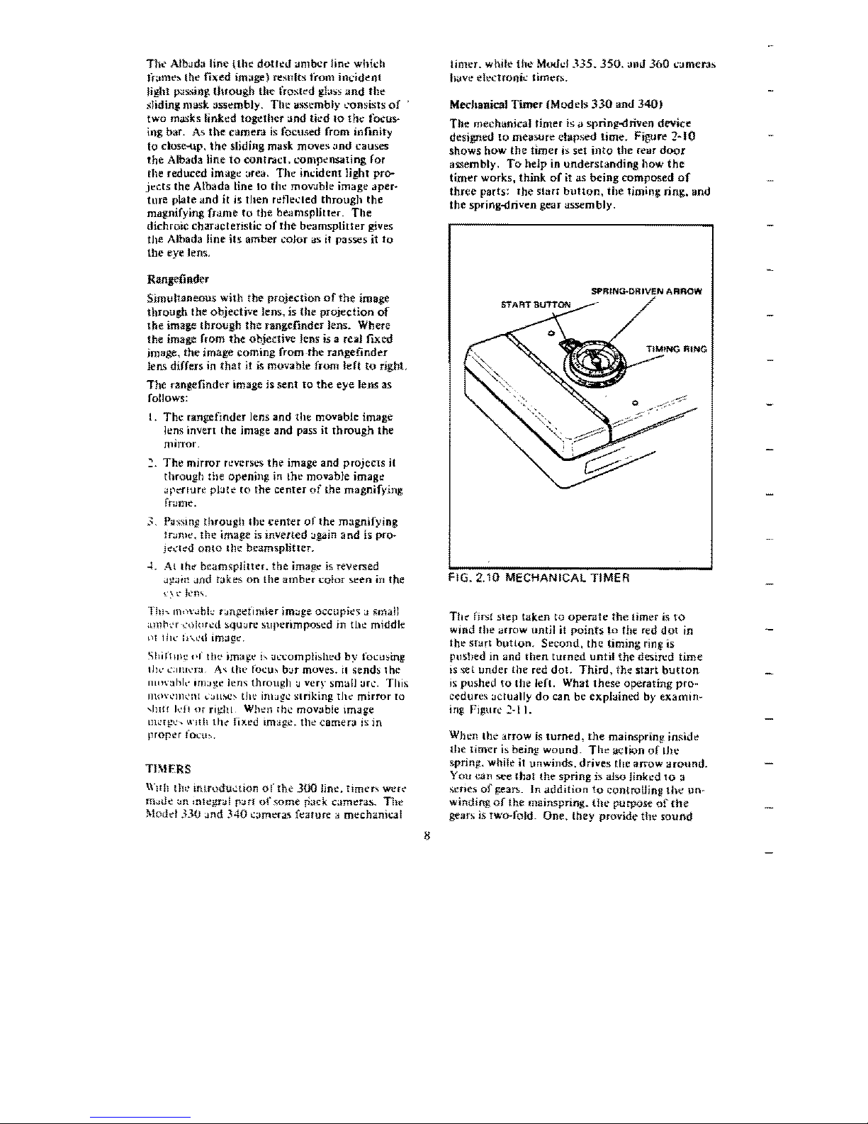
The
mechanical
timer
is
ii
sprin~riven
device
designed
to
mea5Ure
elapsed
time.
Figure
2~IO
shows
how
the
timer
is set
into
the
rear
door
assembly. To
help
in
understanding
how
the
timer
works,
think
of
it as
being
composed
of
three
parts:
the
starr
button,
the
liming: ring. and
the
spring-driven gear assembly.
FIG.
2.10
MECHANICAL
TIMER
The
fjrs:t
step
taken
to
operate
the
timer is
to
Wind
the
arrow
until
it
points
to
the red
dot
in
the
snm
button.
Second,
the
timing ring is
pushed
in and
then
turned
until
the
desired
time
is 'iet
under
the
red
dot.
Third,
the
start
button
is:
pushed
to
the left. What
these
operating
pro~
cedures actually
do
can be explained
by
examin~
ing
FigurL'
2·11.
When
tilt' arrow
is
turned,
the
mainspring
inside
the
timer
i!l
being
wound.
The
action
of
(Jle
spring. while
it
unwinds.
drives rhe
arrow
around.
You
can
see
(hat
the
spring
IS
also linked 10 a
"ene:.
of
gean..
In
addition
to
controlling
the
un·
winding
of
the mainspring.
the
purpose
of
the
gears
1s
two-fold.
One,
they
provide
the
sound
-
-
-
-
-
-
-
r--.,
STARr
BUTTON
LeVeR
lENGAGEDJ
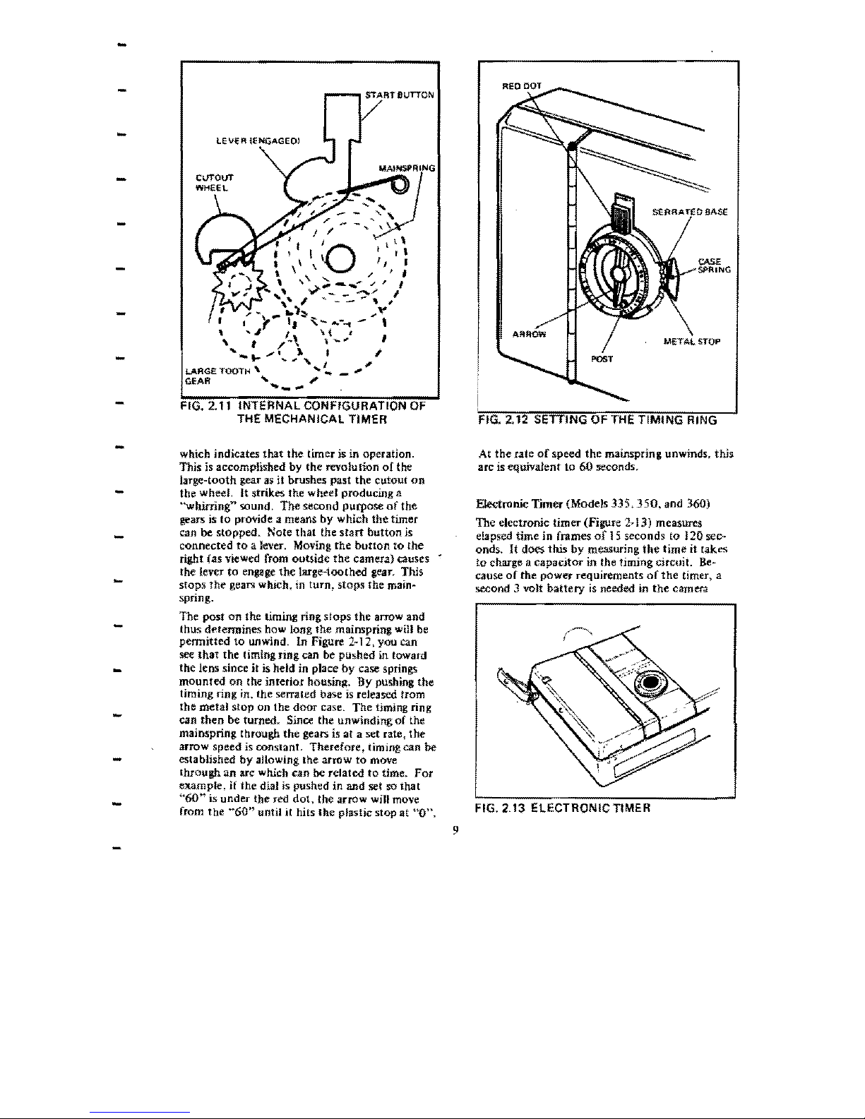
FIG.
2.11
INTERNAL CONFIGURATION
OF
THE MECHANICAL TIMER
-
which indicates
that
the
timer is in operation.
Thls
is
accomplished
by
the
revolution
of
the
large~tooth
gear
as
it brushes past
the
cutout
on
the wheel,
It
strikes the
whed
producing a
-
''wltirringn sound,
The
second purpose
of
the
gears is
to
proVide a means by w hleb
the
timer
-
can
be
stopped.
Note
that
the
start
button
is
connected
to
a Ie\'er. Moving
the
button
to
the
right (as viewed from outside
the
camera) causes
the lever
to
engage
the
large-toothed gear. This
-
stops
the
gears which. in
tum,
stops
the
main~
spring,
-
The
post
on
the timing ring Slops
the
arrow and
thus determines how long
the
mainspring will be
permitted
to unwind. In Figure 2-12, you can
see
that
the
liming nng can be pushed in toward
-
the
lens since
it
is held in place
by
case springs
mounted
on
the interior housing.
By
pushing
the
timing ring in.
the
serrated base
is
released from
-
the
metal
stop on
the
door
case.
The
timing
ring
can
then
be turned. Since the unwinding
of
the
mainspring through
the
gears is
at a set
rate,
the
arrow speed is conslanL
Therefore,
timing can
be
established
by
allOWing
the
arrow
to
move
-
through
an
arc which can be related
to
time.
For
example,
if
the dial is pushed
in
and set so Ihat
-
"60"
is
under
the
red
dot,
the
arrow will move
from
the
"60"
until
it
hits
the
plastic stop
ilt
"0",
9
FIG. 2.12 SETTING OF THE TIMING RING
At
the
rate
of
speed
the
mainspring. unwinds. this.
arc is equiVatent
to
60 seconds.
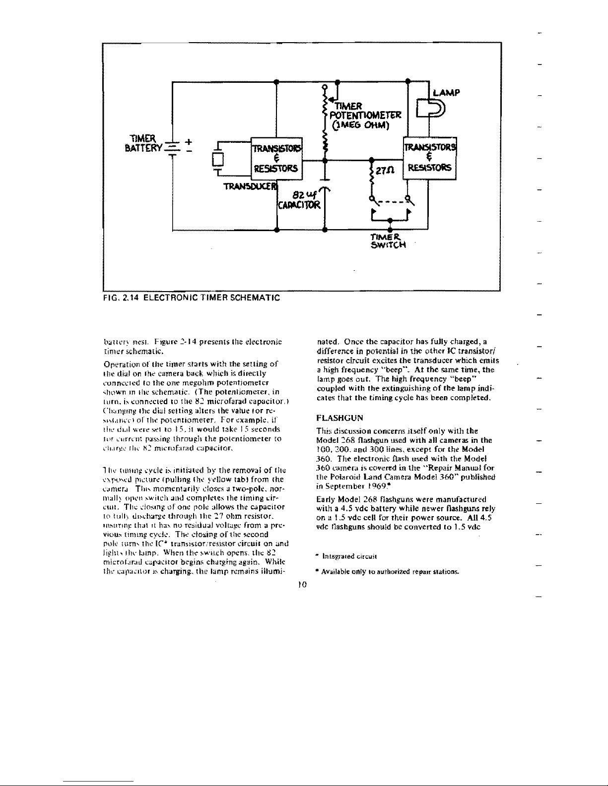
Electronic
Tjmer
(Models 335,
350.
and 360)
The electronic
timer
(Figure 2~13) measures
elapsed time
in
frames
of
15
seconds to J
20
sec~
onds.
It
does
this
by
measuring
the
time
it
takes
to charge a
capacitor
in the timing circuiL
Be~
cause
of
the
power
requirements
of
the
timer, a
second 3 volt
battery
is
needed in
the
camera
FIG. 2.13 ELECTRONIC TIMER
+
FIG. 2.14 ELECTRONIC TIMER SCHEMATIC
b;,jtl\:.'r~
1l~$1_
Figure
~~
14
presents
the electronic
timcr
schematic.
Operation
of
the timer sfarts
with
the
setting
of
I
he
dial on Ihe camera back which
is
directly
n.:mn<:l.:lcd
to
the
one
megohm
potentiometer
"hown
In
Ihe schcm.uic.
(The
potentiomeIer, in
[urn,
j"
connecled
10
the
g~
microfarad
capacitor.)
Cb:II)~mg
lhe
dial
Selling
aiters
the
value
[or
rt!-
"1\l.tnn'j
of
tilt'
pOlentl()meteL
For
example.
if
Ib\.,
til.11
wefe
s.:!
to
15.
it
would
take
15
seconds
lilT ",'lIrrdH
rJ~ing
Ihroug.h
the
potentiometer
to
dUf}!4"
111\'
tC
tnlt:rof:uad
capadtor.
11l~'
tllm:l~
..:ydc i" imtl:.lh:d
by
the
removal
of
tht;
'.-'\!,pwu
plo..:wrl!"
(Pulhng
Ihe yellow
tab,
from
the
,::,JmcrJ
Till'-
momentarily
doses:J
two~pok.
OOf-
mall;.
()p~'n
"wlleh
JIllJ
completes
the
timing
dr~
tun.
TI1-.:
dosm~
or
one
role
allows the capacitor
10
lull)
tl!:-.dl~T}!e
throtl~h
the
-;'7
ohm resistoL
IIbmIllJ.~
tll:J!
It
ha"
no
resiuuaJ
voha~c
from a pre-
VIOU~
fimmg
cyck.
The
dosin,g
of
the
~econd
puit'
HIm'
til.:
Ie·
trunslstocreslstor
cin:uil
on
and
l!~hh
Ilh:
bmr"
\\'hen
the
"wHeh
orens.
thl:!
g2
mit:roIJr;u.l
cap~..:ltor
begins charg.ing again, While
lIlt'
Lap:J.:llor
l~
charging. tht: lamp remains iilumi-
nated,
Once
the
capacitor
has
fuJly charged, a
difference in potentiai in
the
other
Ie
transistorl
resistor
circuit excites
the
transducer
which emits
a high frequency
"beep",
At
the
same
time,
the
lamp goes
out.
The high frequency
"beep"
coupled with
the
extinguishing
of
the-
lamp
indj~
cales
that
the
timing cycle has been completed,
FLASHGUN
This discussion concerns Hself
only
with the
Model 268 flashgun
used WIth all cameras in
the
fOO,
200.
and
300
lines,
except
for
the
Model
360.
The
e)ectronJc flash used
with
the Model
360
earner
.. is covered in
the-
"Repair
Manual for
the Polaroid Land Camera Model
360"
pubUshed
in
September
1969.*
Early Model
268
nashguns were manufactured
with a
4.5
vdc battery while newer nash guns rely
on
a 1.5
vdc
cell for their
power
source. All 4.5
vd.c
flashguns should be converted
to
1.5 vdc
• lntegt31ed circuit
* Available
only
to
authorized repair stalions..
10
a~.:ordmg
to
m~[rl.u:tions
in
the
Repair
and
has a
bayoneNYpe
plug which pushes asjdc
i.I
-
Adjuslmenl
Ptoce;,.h.ln
..~ seclion
of
this
m<lnU<lt
(Tbl.'
Ilrinc,,~tes
of
operation
ciled for
the
l.5
vde
t'kl~h,"n
~lQW
also
apply
to
Ihe early
4.5
vd.;:
models,"
-
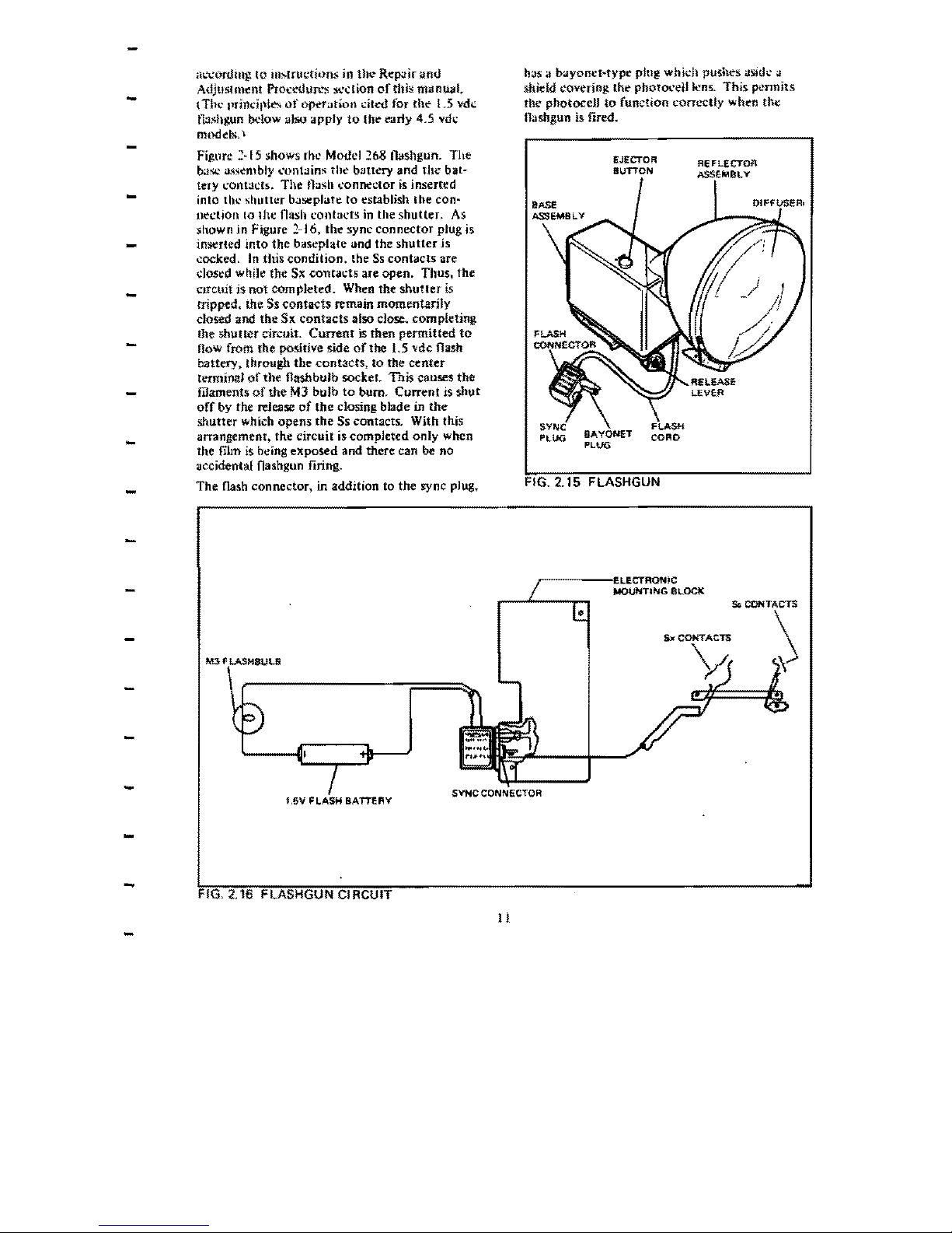
Fi,fl.urc
:!·15 shows rhe Model
::68-
(btshgun.
The
base assembly
....
ontains
the
bau«)'
and
the
bal-
tery I;ontacts. The nash I.'Onne-clOf
is
inserted
-
into the shuttl:T baseplafe to establish
lhe
con~
ne~lion
10
Ihc
nash
contacts
in
the
shutter.
As
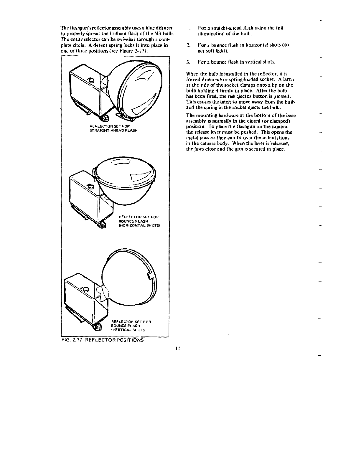
shown jn Figure 2-16, the sync
connector
plug is
inserted
into
the
bastplate
and the
shutter
is
-
cocked.
In
this <:ondition. the
Ss
contacts are
dOSt:d
while
the
Sx
contacts
are open. Thus.
the
CJfcuit is
not
completed.
When the
shutler
is
-
tripped. the Ss tontacts remain momentarily
dosed
and
the
SK
contacts
also
dose.
completing
the shuBer circuit.
Current
is then
permitted
to
now
from the positive side
of
the
1.5
"de
flash
battery. through
the
contacts,
to
the
center
termina'
of
the flashbulb socket. This causes
the
-
filaments
of
the
MJ bulb
to
bum.
Current
is
shut
off
by
the
release
of
the
closing blade
in
the
shutter
which opens
the
Ss contacts. With this
arrangement, the Circuit is completed
only
when
-
the film is being
exposed
and there can
be
no
accidental nashgun firing.
-
The
flash connector. in addition to the sync
plug,.
"'''',!.IoS.BULB
-
-
-
-
-
SYNCCOI~~~------I
BATTERY
FIG. 2.16 FLASHGUN CIRCUIT
II
shidd
covering the
photOl.'eU
lens.
This
pennits
the photoceU
to
function correctly when the
nashgun
is
fired.
EJECTOR
BUTTON
FLASHGUN
MOUNTING
BLOC"
FIG.
2.15
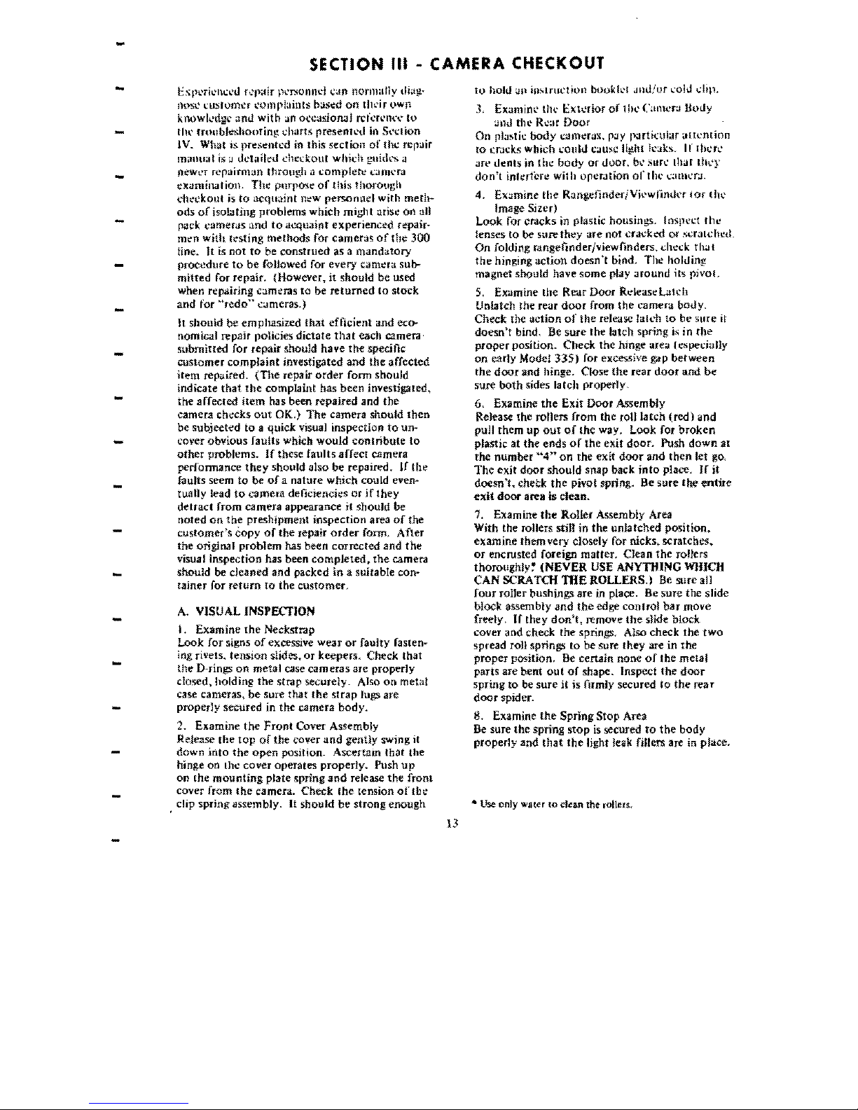
Tht"
rlashg:un's reflector
as~mbly
lISl?S
a blue diffuser
I,
For
a
$truit:ht~aheaJ
l1uJ>h
u~in!!
(hL'
full
to
properly spread the brilliant flash
of
the
M3
bulb. iUumination
of
the bulb.
The entire relettor can be swiveied through. a
com~
pJete
circle_
A detent spring locks it
into
place in
.,
For
a bounce flash
in
horizontal shots
(to
one
oflhree
positions
{see
Figure
2~17):
get
sofllighl).
REFI.,EC10R
SfT
FOF!
SOUNCE
FlASH
IVERTiCAl
SHOTS)
3.
For
a bounce flash in vl?rtical shots.
When the
bu1b
1S
instaUed in the reflector, it
is
forced down into a
spring~loaded
socket. A latch
at the side
oUhe
socket clamps
onto
a lip
on
the
bulb hoMing
it
firmly in pJace. After the bulb
has been fired. the red ejector
button
is pressed.
This causes the latch
to
mO'Ye
away from the bul;,
and the spring in
the
socket ejects
the
bulb.
The mounting hardware at the bottom
of
the
base
assembly
is
normally in the closed
(or
clamped)
REFl.ECTOR
SET
FOR
position. To place the flashgun
on
the
camera,
STRAIGHT·AHEAO FLASH
th~
release
lenr
must
be
pushed. This opens the
metal jaws
so
they can fit over the-indentations
in the camera body. When
the
lever
is
"released.
the jaws close and tbe
gun is secured in place.
REFLECTOR
SET
FOR
BQUNCE
FlASH
iriORIZONTAL SHOTS)
FIG. 2.17 REFLECTOR POSITIONS
12
-
-
SECTION
III
- CAMERA
CHECKOUT
i:XPl'Tk'lll.:l'l.I
f';jlair
pl'r.oonnd
C~II'I
normally
di.ag:·
to
hold
<.11\
iUlolrllction booH.'1
JuJ/ur
l'O!J
diP,
!1tlSl'
I;uslomt.'r t'omp!:lints based
on
tlll'ir
own
knowll..d!!C
and
with
an
oecasiorull rclcn,'IH'\'
(0
-
tin-
troubleshoofin!;
dHirts
presenTcd
ill
S{·J.:tion
IV. What
.s.
pre~ntcd
in
this section
of
the repair
manual
I;; J detailed
ched:ollt
whidi
gllidt's a
newt'f
rCraimlan
through a f.:omph:h: !"'uml'ra
-
!!XaminalioJ). The
purpose
of
this
thorough
chl!'ckout is
to
acquaint
!leW
personnel
with
meth-
ods
of
iso!i!ting
problems
which
might
urisr:
on
all
-
pilck
cameflls and
to
acquaint experienced
repair~
men
with
(('sting methods for cameras
of
the 300
line. It
is
not
to
be construed as a mandatory
-
procedure
to
be foUowed
for
every caml!'ra sub-
mitted for repair, (However,
it
should be used
when
n:pa.iring
cameras
to be
returned
to stock
-
and
for
"redo"
c<.Imeras.)
It
should
be
emphasized
that
efficient and eco-
nomical repair polide5
dictate
that
each camera·
-
submiued
for repair should have
the
specific
customer
complaint
investigated
and
the
affected
item
repaired.
(The
repair
order
fonn
should
indicate
that
rhe complaint has been investjgated,
the
affected
item
has
been
repajred and
the
-
camera dH:cks
out
OK,)
The
camera should
then
be subjeeted to a quick
vIsual
inspection
to
un·
cover obvlous faults which would
contribute
to
-
other
problems.
If
these faults affecr camera
perfonnance
they
should also
be
repaired.
If
the
faults seem
to
be ofa nature which could
even~
-
rually lead
to
camera deficiencies
or
jf
they
detract
from camera appearance
it
should
be
noted
on
the
preshipment Inspection area
of
the
customer's
copy
of
the
repair
order
fonn, After
-
the
original problem has been corrected and
the
visual inspection has been compJeted.
the
camera
-
should
be
cleaned
and
packed
in
a suitable con-
taIner for
return
to
the
customer.
-
A.
VISUAL INSPECTION
I.
Examine
the
Neckstrap
Look for signs
of
excessive
wear
or
faulty
fasten~
iog ri\'ets, tension slides,
or
keepers. Check that
-
the
D-rings on metal case
cameras
arc properly
closed, holding
the
strap securely. Also
on
metal
case cameras,
be
sure
that
the
strap
lugs are
properly secured in
the
camera
body.
-
2. Examine
the
Front
Cover Assembly
Refease
the
top
of
the
cover
and
gently swing it
down
into
the
open
position. Ascertam that
the
-
binge on the cover operates
properly.
Push
up
on
the
mounting
plate spring
and
release
the
front
cover from
the
camera. Check
the
tension
of
tbe
-
clip spring assem bly.
It
should be strong enough
13
3, tXaminl' thl'
l:::xt
....
rior
or
1 Ill'
(';UHCr;.l
Body
;,md
the
RC;,f
Door
On
pla~tic
body
cUmerux,
P:JY
IXirticlll;u
altl:nrion
[0
~r.:lI':ks
which
could
cau:;C
Ii~hl
leaks.
Ir therl'
.In.'
dents
in
the
body
or
door,
bl> SIIrC (hat
Ih>.'j'
don't
interfere wil h opcr.ltion
or
t Ill'
",:Ulll'r;J.
4.
EX:Jmine
the
RangefinderjVil'wlintkr
lor
till'
Image Sizer)
Look for cr.tcks in plastic housings. Inspcl:t
rhe
lenses to be sure
they
are
not
..:-rackcd
or
sa;.ll..:-hed.
On
foldjng rangelinder/viewfinders. dlCt:k th;Jt
the
hinging
action
doesn't
bind. Tilt: hokling
magnet should have
some
play
Jround
its
pivol.
5.
Examine the
Rt"J.r
Door R.:leaseU1I."h
UnlatCh the rear
door
from
the
camer.! bouy.
Check the
action
of
the
release latch
to
be
sure it
doesn't
bind, Be
sure
the
latch spring is in
the
proper
position.
Check
the
hinge area lespedaIJy
on
carty Mode! 335) for excessive gap
between
the
door
and hinge. Close
the
rear
door
and
be
sure
both
sides latch properly.
6. Examine
the
Exit Door Assembly
Release the roners from
the
roll
latch
(red)
and
pull them up
out
of
the way. Look for
broken
plastic at
the
ends
of
the
exit
door.
Push
down
at
the
number
«4»
on
the
exit
door
and
then
let
gO,
The
exit
door
should snap back
into
place,
If
it
doesn't.
check
the
pivot spring. Be
sure
the
entire
exit
door area is clean.
i,
Examine
the
Roller Assembly Area
With the
rollers still
in
the
unJatched position.
examine them very closely for nicks.
scratches~
or
encrusted foreign
matter.
Clean
the
rolters
thoroughly~
(NEVER
USE ANYTIlING WIlICH
CAN
SCRATaJ
TIlE
ROLLERS.)
Be
sure
311
four
roller bushings
are
in place. Be sure
the
slide
block assembly
and
the
edge conlrol
bar
move
freely,
If
they
don't.
remove
the
sUde
block
cover and check
the
springs, Also check
the
two
spread ron springs to be sure
they
are in
the
proper
position,
Be
certain
none
of
the
metal
parts
are
bent
out
of
shape. Inspect
the
door
spring to be sure
it
is
otmly
secured
10
the
rear
door
spider.
8.
Examine
the
Spring Stop Area
Be
sure
the
spring
stop
is
secured
to
the
body
properly
and
that
the
light leak fillers are in place.
•
Use
only water
to
clean the rollers,
9.
f\.uuint'
lilt'
Ih'llow
..
Mnllllis
Tlh-'
14 ml'lal taos
on
the
bal;k
or
rhl'
bt.:Uow:o
should
!,h.'
I'n.'~"i.,
..
d tiglllly
a1!:!insi
the
~uloUfs
in
lh,,'
t:amem
body.
On
some
,,',U11l'tas, four
PhJUir~
hl'atl scrl'WS hold
the
fronl
of
the
bellows:
to
Ihe
,,!lnrkr
housing. On
other
J:ameras. four plastic
'>lUds
>In.'
held
by
bellows rash'ncrs.
In
either
l,.'OISC',
he
cerlain
th>lt
the
front
of
the
bellows is held
rig.htly ;'lg;Jinst
the
:ilmth.'r housing. Be
sure
tbe
light se:ds are
in
plo:tce.
10.
tXUmlJle
the Rear
lens
Be
sun!
the
lens
is
not
cr".I(;ked
or
scr"Jtched.
Clean
tbe
lens thoroughly.
11.
EX;lmine
the
Focu:iing. Linkage
Close tlil' rcar
door
of
rhe
camera
and
eXlend
the
bdlows.
Observle
the
action
of
the focusing
link~
ajJ<'
"" Ihe bellows
is
extended.
It
should allow
Ihe
bdlowl'
to
pop
out
when
the
righl focus
but~
ton
il'
raised. When
the
shutter
housing is pulled
our
alilhe
way. you should be
able
to
hear a
"cllck"
as
tbe
top
tnner
frame
locks
into
posjtlon.
Close
;.md
then
extend
tht
bellows.a few mOre
11Jnes
10
be
SlIT!!
there
are
no
binds
in
the
move~
ment. EXdmine all metal
parts
to
be sure
they
are
not bent. Push the focus
buttons
back
and
forth
;1
f,,'w
lime,>
10
check
on
the
smoothness
of
the
r()~'llS.l11g
linkage movement. Also Jook
into
the
r:llll:!efillder!viewfinder
to
determine
that
the
fO..:th
~It
j~
prolwrly
\.'Ql.lpled
to
the
optics
assem~
hi},
Whl.'r,,·
applicable. check
the
condition
of
the
fa~1
fO('th
d..:(al
On
riw
righl focus
button.
Also
ch,,'(1..
liTt:
shutler
sh;)ft
to
be sure it is
oot
bent
\Jr
IT.ld:l'd.
I ~ l:.,\.WHlk
!h~'
Exterior
of
the
8ello
.....
s
l<lol..
In;
a !'I,'par;lli<m
of
the seam
at
the
bottom
of
(ttl'
bdtows
and for any
deterioration
of
the
bdlmv
..
IH;.ti('rial.
;3,
I
\.lmllh·
th~'
Sil\l!!\.'r
Aclion
\\1111
11:\,
t'dll1w,,'!IU
I?x!I.-'llucd.
cot:k the
shuncr,
!
lh
IHlllll<n.;
b1](\t'"
"hotdd
move
down
smooth~
I:
mit'
pL!4'~·.
Prl',!'1
tli,,'
..
Ilutter
releu~
bufton.
1
h:
I';unlh~'r
J
hUHO»
should
move
bJJck
up
,mo\1
1
1];!:,
and
tWo
"clkks"
should be heard
under
hm
h!l'hJ
\.·ondilious.
If
these
criteria art'
not
met,
,'i:.yk
~l.ll
h'r~
n)h;!f!~'
J:nd
wiring and
then
the
'!illlll'r
IIller!o,-'f;,
l(t!1l'se an.' OK, l·onsult thl'
·-Rcj'.p;
\L,n\l~d
(\11
,\lItOIl);llio..:
ShtIHl'r.,"
pun·
jl',h"d!tl
\1.1:. !
'1
1
,>-,
01
it
a
Modd
300. consul!
::~,'
"R':P:Jlf
:\h!l~llal
on PolarOld
land
Model
360
1
.lllL'!.I··l'l!h:l~il~'d
III
S..'!Hcmbl'r. 1(}69.·
14. Examitl\.'
th~
Slmu\.'r
Rd~<lSt·
Al'lion
In
conjunction
WHir
step
13.
ubs~r'l\.'
thl'
;)~tioll
or
Ihe
shuttcr
release
button.
Till'
button
:-.huuJd
trip
the
ShUtll'r 'when
ii
is
<It
Hbout
the
S;:1Pll'
kvd
<IS
the
lop
of
the
shuth:r
rdcOASC'
bezel.
A.
special
test for this
is described later in this sci-'tion.
is.
EX<lmine
the
Action
of
the
Aperfufl'
Whei.'!
or
Film Speed Slide
Tum
the
apc-rture
wbeellhrough
its
four
settings
(two
setting,o;
on
some
l,.'tIllleras)
and
ubsc-f'Vl'
(through
thc-
front
tens)
that
the
apertures
are
changing
properly.
Reset the scene selector
and
repeat.
If
dny
probiems
are evidenced. consult
the
"Repair
Manual
on
Automatic
Shutters."
On
other
camer.ls. move
the
film speed slide
back
and
forth
and
observe th:.d
the
apertures. visible
through
the
front
lens. change. If problems
are
eVident.
consult
the
"Repair
Manual
on
Auto-
ma~jc
Shutters.""
1
b,
Examine
the
"Darken~LightenH
Control
Move
the
Jens bezeJ ("darken..Jlghten" (:untror)
through
its full travel. Listen for
any
binding
whieh might
indicate
a malfunction. Ir
the
con--
trot
does
not
move
freely, consult
the
"Repair
Manual
on
Automatic
Shutters."
J7, Examine
the
Front
Lens
Carefully
inspect
the
front lens for cracks
or
scratches. Be sure
it
is clean,
18, Examine
the
Photoed
I Lens
Be
sure this lens is free from
cracks
or
scrJlches
and
is
dea
o.
19. EXdmine
the
Top
Etch
Plate
and
the
Front
Etch Plate
111e
plates Should be clean
Dod
free
of
blemishes,
They should
be
finnly secured
at
their
comers,
:::0.
Examine
the
Tabs
on
the Bellows
Be
sure
the
tabs
hording (he
shutter
release cable
and
the b.lttery wires are secure.
21.
Examine
il1e
Battery
Compartment
('lo..e
till.'
oeUows and. if applicable. fold
the
f;.:lIlgcfinder/Vlcwfinder. All cameras
excepl
Model
360:
Open
the
battery
compartment
door.
The
jatch
should hold
the
door
llrmly
und
there
should be
no
play in tht'
door.
Be
sure
the
door
lIm!!C'
isn't
henl.
Close
tlli.~
door
again.
It
should
snaIl shut.
Modd
360:
Use a pencil point
to
free
the
left~
hand
!!uurd which
l,.'Qvers
the batteries.
Tilt:'
hand~
gU;lrtllatch shouh'! llold
the
guard securely. Check
thut Ihe handguurd has a
battery
pad glued in '
plaLe.
Be
sure
the
upper
tab
(which fits inlO
the
l·tllout in
the
battery
compartmenl J isn't
broken
or
trucked, Replace Ihe
haodguard,
It
should
SI1#P into place.
14
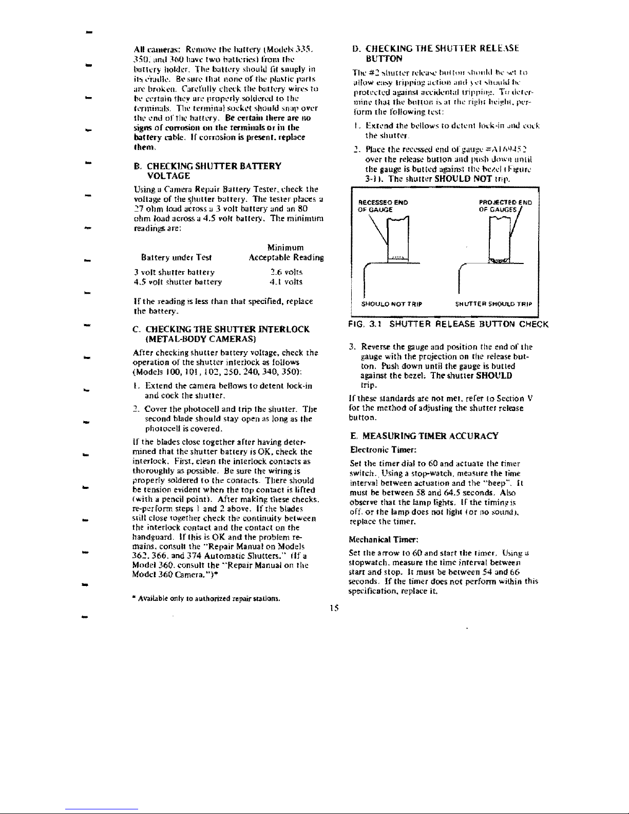
-
All cameras:
R~·tlH)v(,
the haUery (Model" 335.
O.
CIIECKING TilE
SHUTTER
RElUSE
.'5:0,'
,Iflll
_~{lO
ha'Yc
two
b'lth..'ricsi from
rh\,'
BUTTON
buril.:ry holdc:r. The h:.IUt.'ry should
fit
!>nup.ly
in
Tht..'
#::
':'\hulh.'f
rl.'ll'il'>t..'
!l\!ll\m "holdd
th."
.....
·t
to
it:, ",'mdk.
B~
$lIr~~
fhat
!loth,'
of
thl' Illusrk
p;lrts
,In:
bmken.
Cardully
dll.'t'k th(' b.llh:ry win.'s
to
bl'
(l"r1<lIo
they arl' propl'rly
soldo:r.,,:t,I
to fh...
-
knlltn:.lIs. The terminal
sock~t
should SOUl) over
thl'
....
ml
ofthl..' bath.'fY.
Be
certain there are no
signs
of
corrosion
on
Ihe terminals
or
in
ahe
bantry
cable,
If
corrosion is present. replace
.iwm,
B.
CHECKING
SHUTTER
BATTERY
VOLTAGE
Using a Camera Repair
Battery
Tester. check
the
- voltage
of
the
~huner
battery.
The
tester
places
lJ
27
ohm
load ueres:; jJ 3 volt buttery and
an
80
ohm
IO<id
across. a
4.5
volt battery,
The-
minimum
-
readings are:
Minimum
-
Battery
under Test Acceptable Reading
3 volt shuTter battery
~.6
volts
4.5 volt shutter oottery 4.1 volts
-
If
the
reading
IS
less than
that
specified, replace
the battery.
-
C.
CHECKING
TIlE SHUTTER
INTERLOCK
(METAl-BOOY
CAMERAS)
After checking
shutter
battery
voltage, check
the
-
operation
of
the
shutter
interlock
;)s
foUows
(Model, 100, 101, I
O~,
150. 240. 340, 350):
l,
Extend the camera bellows
to
detent
lock~in
and
cock
the
shutter.
.,
Cover the photocelJ
and
trip the shutter.
The
second blade should stay
open
as long as
the
-
pholOcelJ is covered,
If
the
blades. close
together
after having deter-
mined
that
the s.hutter
batlery
is OK. check the
interlock. Fjrst, clean
the
interlock contacts as
thoroughly as possible. Be sure the wiring is
-
properly soldered
to
the
confacK
There should
be tension evident
when
the
top
contact
is
lirred
(with a pencil point). After making these
checks.
re-perrorm steps J and 2 above.
If
the blades
-
slill close tOgether check the continuity between
the interlock contact
and
the contact on the
handi!uard.
If this is
OK
and
the
problem
re-.
mainS:.
consult the
"Repair
Manual
on
Models
-
36~.
366,
and
374
Automatic
Shutters."
(If
li
Model
360.
consult
the
"Repair
Manual on
the
Model
360
Camera. ")'"
-
• Available only
to
authorized
repair SQiJons"
IS
,I
!low
t:;I:o.Y
IriPllilll!
;h:fiUi)
;1Ilt!
>,,'1
...
hu\llti
h~'
rroh:dL'd against
~J\,:\:itll.."nl;ll
trippinE!.
To d...
·ll·r·
mine tlwt the buHon
i~
a1
[h.:
fi,!!hl
hdghl.
r'l'r~
form
the
following lest:
I. EX[l'nd the
bdlows
to
dl..'ll..'nt
IOl"k-in
,lni.l.:od;.
the
shuHl!r_
"l
Plat'e
the
re('l'sscd
eJUl
of
gotH;!\,.'
~ r\
16\),J:-;
~
over the release
button
and push
dowl1
unlit
the
gauge
is
butted
against
till'
h':ld
I
Flgtlrl.'
3-)).
The
shutter
SHOULD NOT
trip.
RECESSEO
Ef04C
OF GAuGE
SHQULOt-,lOTTFlIP
SHUTTER
SHOULD
TRIP
FIG.
3.1
SHUTTER
REL.EASE
BUTTON CHECK
3. Reverse the gauge and position the end
of
the
gauge with the projection on
fhe release but-
ton. Push down until the gauge is bulled
against
the
bezeh
The
shutter
SHOULD
trip.
If
these standards
are
not
met. refer
to
Section V
for
the
method
or
adjusting
the
shutter
release
button.
E.
MEASURING
TIMER
ACCURACY
EJeclronic Timer:
Set the timer dial
to
60
and
actuate
the timer
switch .. Using a stop-watch, measure the time
interval between actuatIon and
the
"beep'".
It
must be between 58
:and
64.5 seconds. Also
observe rhat
the
bmp
tights.
If
the-
timin!!
is
orr.
or
the
lamp does not light i
or
no sound).
replace
the
timer.
Mechanical TImer:
Set
the
arrow
1060
and start
the
rimer.
Ulolng
a
stopwatch. measure
the
time interval betweell
start
and
stop.
It
musl
be
between
54
and
66
seconds.
If
the timer does
not
perform within this
specification. replace
it
.
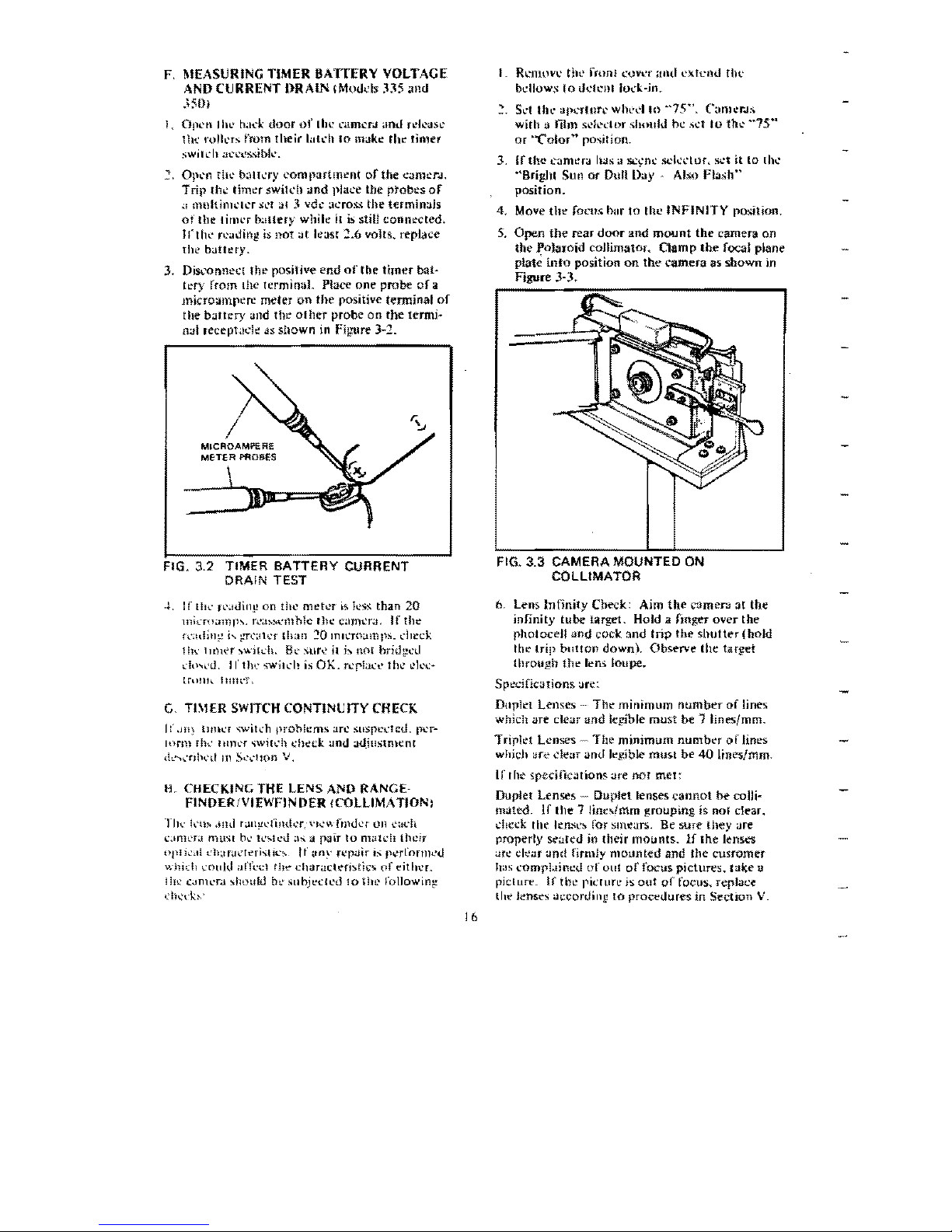
F. MEASURING TIMER BATTERY VOLTAGE
AND
CURRENT IlRAIN
(Mol.h:ls
.ns and
J50;
1,
Olll'tllhl'
h~h.:l
door
of
Ihl:
~'ilmCrJ
and rdcasc
llh' rolll.'ts from their
lutdl
10
make the limer
:,>wil':
It
;l1:"'
..
's:~ibk,,
1-
Op~'n
tli,,' b:lll..:ry
compartment
of
the cameTJ,
Trip
(il..:
timer swih:h
and
place the probes
of
;1
lllultinH,,'lcr :':I.,t al 3 vde
;H:ro!>.~
the terminals
of
the
litlh.'r
b;llh~r>'
while
it
is stili connl!cted,
Irtl1,,' n.'ading
is
not
<.It
least
:1.6
volts. replace
thl'
battery.
3. Disl'Onne;;!
lhe
positive end
of
the
timer
ba:t·
h:ry rrom the terminal.
PI<lce
one
probe
of
a
microampere meter
on
the
I)ositive terminal
of
the
baltl::ry and
the
oiller
probe
on
the
termi~
nal
reeeptade
dS
shown
in
Figure
3-:1.
FIG, 3,2 TIMER
BATTERY
CURRENT
DRAIN TEST
4, If
tlK
fl'.IUil1J,! on
till'
metl'r
is
ll'~
than
20
lHhTO.lllllh,
n.':1~:.
...
·l11hlc
Ihe
C:l)T\cr~j.
If
the
f(';\dll1:':
i,
g-r~'~I1~'r
than
~O
Imcro;)n!lh"
check
lIh'
1
][)H'f
",';:111:11,
BL'
~ur<'
i1
j,.
not
brid1,!ed
~'!ll~"U,
II'
tlw
~wjll:l!
is
OK.
rcpJac,-' thl?
I?k'c~
U.Ulk
111111."1',
G.
TI\IER
SWITCH
CONTINl:ITY CHECK
I:'
,JIl~
ll/Hl'f
>;wih:h
prohlems
arc
sU$pt:dcu,
p"'r-
Inrm
f!h'
l!llll'f
",witl.'h
l'hecl
and
;Jujustment
,L',,'niwd
III
S~'l'llOn
V,
H.
CHECKING
THE
LENS
AND
RANGE·
FINOER/VIEWFINOER !COLLIMATION,
Til..,
kll"
,1Ild
r<.lll~l'nlHh.'r,
\'I~'"
finu",!'
011
each
ClJlh'r;! mlNI
bo.'
ll',.!l."d.1S a
pair
to
match
their
opli":,II
t'h;Ir:.tL'lrri'itil.·,
It
.my
repair
is
pcrrornwu
whidl
~Ottld
011'1"('1,.'1
the
char01clC'ri:.ril;:.
of
t'ithcL
III":
(Jm'
• .'ra
~h<JlIl,j
h~'
SlI
bjt't:!
I.'U
10 i he
fo 1I0w jnt!
d)..;d(~·
I.
Rt:mo\,I,,' till.'
frun!
1..'"0\'\.'1"
.lnd
l'X!t.'OU
rhl,.'
bdlow
....
10
dclCni loc-k-jn.
~
Sd
th\.·
apcrlnre
whed
to
"'75".
Cuml.'r.ls
with a !ilm Sdl'c-Ior ,
..
lmuiJ
be .,et
to
the
~·75··
or
'''('olm'» position.
3.
,rthe
I.~Jmt:ra
h,as
a
sc~nc
sckl'lur,
set
it
to
Ihl?
"'Brighl
Sun
or
Dun
Day Also
Flash"
position.
4. Move
thr
focus hm
to
the INFINITY
po..
...
ition.
5,
Open
the
rear
door
lind
mount
the
camera on
the
Polaroid
coJlimator.
Qamp
the
focal
p~3ne
plate
into
position
on
the
camera
as
shown in
Figure
3-3_
FIG, 3,3 CAMERA MOUNTED ON
COLLIMATOR
6.
Lens
Infinity
Check: Aim
the
camera
3[
the
infinity
tube
target. Hold a fmger over
the
photoedl
and
cock 3nd
trip
the
shutler(hoJd
the
trip
button
down). Observe
the
tar~et
through
tIl!!-
Ie-ns
loupe.
Spocifications an::
Dtlpkt
Lenses
...
The
minimum
number
of
lines
which
are
clear and legible must be
1Iines/mm.
Triplet
Lenses ~ The
minimum
number
of
Jines
which tlrc
dear
anti legible
must
be
40
Iines/mm.
If t
he
specification"
are
nor
met:
Duplet
Lenses
Duplet lenses
cannot
be
colli-
mated.
If
Ihe 7 linc,imm grouping is nol clear.
dlcek
Itlt'
kn.'l'~
for sml'ars. Be
sure
(hey are
properly
scateu
in their
mounts.
1£
the
lenses
an: d<:ar
and
firmly
mounted
and
the
cusromer
h;JS
compl.Jint:d
of
oul
of
focus
pictures. take a
picture.
If
the picture is
out
of
focus, replace
tht' lenses
<.IcconJillg
[0
proct'uures
in
Section
V.
'6
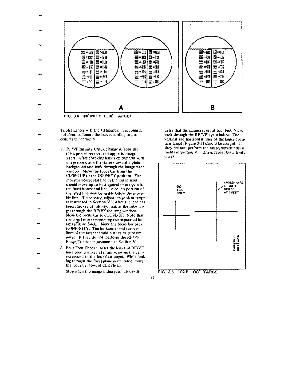
••
-
-
-
-
-
-
llf06.ii
."'IIW
"II"
~
-iillB
:;
-111111
-
-I1i1N
,
11111
iiiioof!ll
~~li~:~
;;;;
"IIliU
»"1111
;;;
",lmO
!OI!IIU
'11m
i!"'~~~
;;"'lliII
~aINP
:::
-1111111
..
nulJ
-lInll
-
'11111
A
ii"IIW
IIwllW
ilI"lIi!ll
::
-11111
=
.IIIID
-11111
=
'11111
B
-
FIG. 3.4
INFINITY
TUBE
TARGET
-
Triplet Lenses -
If
the
40
lines/mm grouping
is
not
clear. coUimate the lens accordlng
to
pro.-
cedures in
Section
V,
-
7. RF/VF Infinity Check (Range
&.
Topside):
(This
procedure
does
not
apply
to
image
sizers, After checking lenses on cameras with
image sizers, aim the fixture toward a plain
background
and
look
through
the image sizer
window. Move
the
focus bar from the
-
CLOSE·UP
to
the
INFINITY position.
The
movable hor-izontal line in the image sizer
should mOlle
up
to
butt
against
or
merge with
the fixed
honzontalline.
Also, no portion
of
-
the
fixed line may be vi..
ible below the mova-
ble line.
If
necessary. adjust image
siler
range
as
instructed in Sect jon V.) After the tens has
-
been
ched:ed
at jnfinity, look
at
the
tube
tar-
get
thrOUgh
the
RF/VF
focusing window,
Move
the focus
bar
to
CLOSE~UP.
Note
that
-
the target moves
becoming two separated
jrn
M
ages (Figure
34A),
Move
the
focus.
bar back
to
INFINITY.
The
honzontal and vertical
lines
of
the
target
should
butt
or
be
superim-
-
posed.
If
they
do
not, perform the RF/VF
Range/Topside adjustments. in Section
V.
-
8.
Four
Foot Check: After the lens and
RF/VF
have been checked
at
infinity, swing
the
cam·
era around
to
the four foot target. While look-
ing through
the
focal plane plate loupe, move
the focus bar toward
CLOSEMUP.
SlOp when the image
is
sharpest This indi-
cales
that
the camera is set at four feet
Now.
iook through the
RF/VF
eye
window.
The
vertical and horizontal lines
of
the larger
crosS'-
hair target (Figure 3-5)
should
be merged,
If
they are not. perform the range/topside adjust-
ments in Section
V,
Then,
repeat the
infinity
cheek,
CROSSHAIRS
HOUtO
900
MERGE
1106
~
AT 4 fEET
ONLY
=
It
Ill'll
I':
.
••
,
FIG. 3.5
FOUR
FOOT TARGET
17
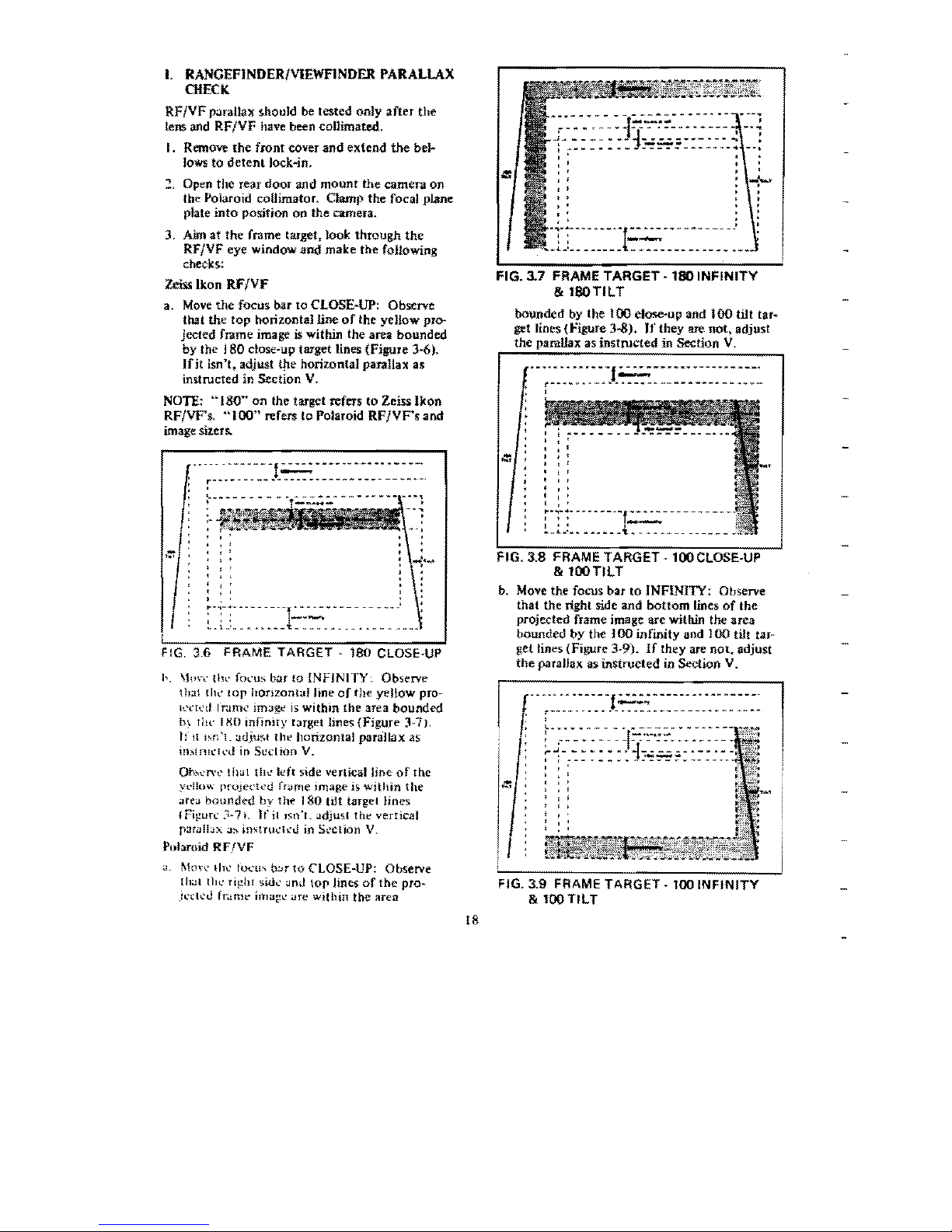
I.
RANGEFINDER/vIEWFINDER PARALLAX
CHECK
RF/VF
p.nailnx
should
be
tested only
after
the
lens
and
RF/VF
have
been
collimated.
I. Remove
the
front cOver
and
extend
the
be}..
Jows
to
detentlock..jn.
"I
Open the rear
door
and
mount
the
camera on
tbe Polaroid collimator. Clamp
the
focal plane
plate
into
position
on
the camera.
3.
Aim at
the
frame target. Jook through
the
RF/VF eye window and make the following
checks:
Zeiss
Ikon RF/VF
a.
Move
the
focus bar
to
CLOSE-UP: Observe
that the top horilontalline
of
the yellow pro-
jected frame image is within
the
area bounded
by
the 180 close-up target lines (Figure
3~6).
Ifit
isn't. adjust ttIe horizontal parallax as
instructed in Section V.
NOTE~
"180~'
on
the target refers
to
Zeiss
Ikon
RF/VF'~
"100"
refers to Polaroid
RFIVF',
and
image
mers.
------
---
---
-!
=-
----------------
r---
- -
--
-~
~
- - -
-- --
-----
~-----~---.
,
,
,
,
~-;-;-
-----
---r·------------
--.:
,
. , ,
-~-.-
,
..
__
_
~_l_'_.~
••
______
••
~.
•
____
FIG.
3_6
FRAME TARGET -
180
CLOSE-UP
I,.
\1\1n: illl'
focu:>
bar
to
iNFINITY,
Observe
tll;11
till.'
lOp
hOtlzont"l
line
of
the yellow
pro-
K'ch'd frame jmage
is
within
the
area
bounded
b~
Iltl' I
XO
inflniry
target lines
(Figure
3-7).
If
II
Isn
'1.
adju~t
t hl'
horizontal
paraJlax
as
in~lnl\'"I,,'d
in
Section
V.
Oh"'..'n't'I!l>.l!
Ihl;'
Il;'ft
5lde vertical
hoe
of
the
ydl()w
projected
fr<trne
image is
within
the
"r!;'>.1
bounded
by Ih..
180
tilt target
Hnes:
I
Fi!!ur~>
3-7 L
If
it Isn 'r. Jdjus( thl' vertical
p:'lri.llln.,J:'
~!l\fHl\'"ll'U
in
Section
V.
Polaroid
RFfVF
>.I,
[\1,lh'
IITl'
focu\
o:Jr
to
CLOSE-UP:
Observe
{hal lhl.'
ri!,!hf
5idl'
Jnd
top Jines
of
the
pro-
jl>c!CU
fr..tmt' image
are
within
the
area
--~-~-------~-~~-.--
~--
..
-~ ~.
--·~l~":'"':!"-~-~·---
-.~
~-~-~·-1-...;.:..w;;w~-~-.":
:
~.~---------~----
---
..
--,
.
FIG. 3.7 FRAME TARGET
·180
INFINITY
&
I80TILT
bounded
by the
100
close-up
and
100
tilt
ta.r~
get lines
{Figure
J...s).
If
they are not, adjust
the
parallax as
instructed
in
Sectlon
V.
.
------..
--.
-f=-····-------.
-.-.
r--·····--·-··---------------···~
,
,
.'
, ,
, ,
, ,
, ,
,
'
, '
, '
:·T:~
~~~-
--·~f.::.::--
----
---
~_"~'.~
••••
__
ol
••
___________
_
FIG. 3.8 FRAME TARGET -looCLOSE-UP
& 100
TILT
b.
Move
the focus bar
to
INFINITY: Observe
that
the
right
side and
bottom
lines
of
the
projected
frame
image
are
with.in the
area
bounded by the J
00
infmity and
100
tilt tar-
get
lines (Figure
3~9).
If
they are
not,
adjust
the
paraJiax as instructed in Section V.
.---...
------f -----------
-------
---
,
r---_..
--.
-.
-.
-
_.
- ---
------
--.-
~
-~-
..
-,
!..~~-~---
_.
-------
--.~-
:
.---··----r.:-:·~-·:::"~·-~----
~
J - - • - - - - •
-J-
-----.--
.-
,
._--
,
,-------~-------------
, .
,
,
FIG. 3.9 FRAME TARGET - 100
INFINITY
&
looTlLT
18
 Loading...