


MVH-2300NEX

MVH-2300NEX
RDS AV RECEIVER
AUTORADIO MULTIMÉDIA RDS
AV RECEPTOR RDS
English Français Español
Installation Manual
Manuel d’installation
Manual de instalación
WARNIN G
WARNIN G
CAUTION
Connection
WARNIN G
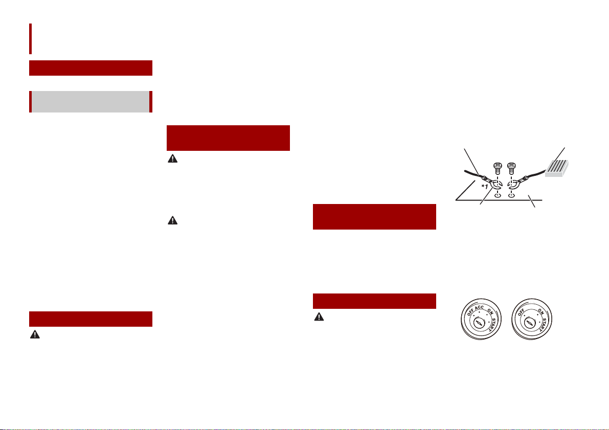
Ground wire
POWER AMP
Other devices
(Another electronic
device in the car)
Metal parts of car’s
body
*1 Non supplied for this unit
ACC position
No ACC position
Precautions
Your new product and this
manual
• Do not operate this product, any
applications, or the rear view camera
option (if purchased) if doing so will
divert your attention in any way from the
safe operation of your vehicle. Always
observe safe driving rules and follow all
existing traffic regulations. If you
experience difficulty in operating this
product or reading the display, park your
vehicle in a safe location and apply the
parking brake before making the
necessary adjustments.
• Do not install this product where it may
(i) obstruct the driver’s vision,
(ii) impair the performance of any of the
vehicle’s operating systems of safety
features, including airbags, hazard lamp
buttons, or
(iii) impair the driver’s ability to safely
operate the vehicle.
In some cases, it may not be possible to
install this product because of the vehicle
type or the shape of the vehicle interior.
Important safeguards
Pioneer does not recommend that you
install this product yourself. This product is
designed for professional installation only.
We recommend that only authorized
Pioneer service personnel, who have
special training and experience in mobile
2En
electronics, set up and install this product.
NEVER SERVICE THIS PRODUCT YOURSELF.
Installing or servicing this product and its
connecting cables may expose you to the
risk of electric shock or other hazards, and
can cause damage to this product that is
not covered by warranty.
Precautions before
connecting the system
Do not take any steps to tamper with or
disable the parking brake interlock system
which is in place for your protection.
Tampering with or disabling the parking
brake interlock system could result in
serious injury or death.
• Secure all wiring with cable clamps or
electrical tape. Do not allow any bare
wiring to remain exposed.
• Do not directly connect the yellow lead of
this product to the vehicle battery. If the
lead is directly connected to the battery,
engine vibration may eventually cause
the insulation to fail at the point where
the wire passes from the passenger
compartment into the engine
compartment. If the yellow lead’s
insulation tears as a result of contact with
metal parts, short- circuiting can occur,
resulting in considerable danger.
• It is extremely dangerous to allow cables
to become wound around the steering
column or shift lever. Be sure to install
this product, its cables, and wiring away
in such so that they will not obstruct or
hinder driving.
• M ake sure that the cables and wires will
not inter fere with or become caught in
any of the vehicle’s moving parts,
especially the steering wheel, shift lever,
parking brake, sliding seat tracks, doors,
or any of the vehicle’s controls.
• Do not route wires where they will be
exposed to high temperatures. If the
insulation heats up, wires may become
damaged, resulting in a short circuit or
malfunction and permanent damage to
the product.
• Do not shorten any leads. If you do, the
protection circuit (fuse holder, fuse
resistor or filter, etc.) may fail to work
properly.
• Never feed power to other electronic
products by cutting the insulation of the
power supply lead of this product and
tapping into the lead. The current
capacity of the lead will be exceeded,
causing overheating.
Before installing this
product
• Use this unit with a 12-volt battery and
negative grounding only. Failure to do so
may result in a fire or malfunction.
• To avoid shorts in the electrical system,
be sure to disconnect the (–) battery
cable before installation.
To prevent damage
• When speaker output is used by 4
channels , use speakers over 50 W
(Maximum input power) and between 4
Ω to 8 Ω (impedance value). Do not use 1
Ω to 3 Ω speakers for this unit.
• When rear speaker output is used by 2 Ω
of subwoofer, use speakers over 70 W
(Maximum input power).
*Please refer to connection for a
connection method.
• The black cable is ground. When
installing this unit or power amp (sold
separately), make sure to connect the
ground wire first. Ensure that the ground
wire is properly connected to metal parts
of the car’s body. The ground wire of the
power amp and the one of this unit or
any other device must be connected to
the car separately with different screws. If
the screw for the ground wire loosens or
falls out, it could result in fire generation
of smoke or malfunction.
• When replacing the fuse, be sure to only
use a fuse of the rating prescribed on this
product.
• This product cannot be installed in a
vehicle without ACC (accessory) position
on the ignition switch.
• To avoid short-circuiting, cover the
disconnected lead with insulating tape. I t
is especially important to insulate all
English
unused speaker leads, which if left
NOTE
uncovered may cause a short circuit.
• For connecting a power amp or other
devices to this product, refer to the
manual for the product to be connected.
• The graphical symbol placed on
the product means direc t current.
Notice for the blue/
white lead
• When the ignition switch is turned on
(ACC ON), a control signal is output
through the blue/white lead. Connect to
an external power amp’s system remote
control terminal, the auto-antenna relay
control terminal, or the antenna booster
power control terminal (max. 300 mA 12
V DC). The control signal is output
through the blue/white lead, even if the
audio source is switched off.
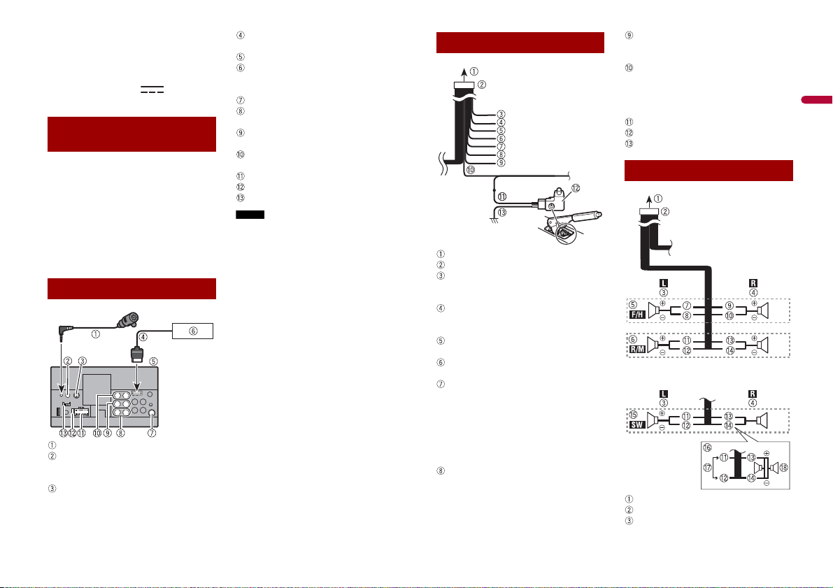
This product
Microphone 3 m (9 ft. 10-1/8 in.)
Wired remote input
Hard-wired remote cont rol adapter can
be connected (sold separately).
SiriusXM Connect Vehicle Tuner
Refer to the instruction manual for
SiriusXM Connect Vehicle Tuner (sold
separately).
RGB cable (supplied with Navigation
system)
This product
Pioneer navigation system
Contact your dealer to inquire about
the connectable navigation unit.
Antenna jack
Subwoofer output (STD)/Low range
output (NW)
Rear output (STD)/Middle range output
(NW)
Front output (STD)/High range output
(NW)
Power supply
Fuse (10 A)
iDatalink adapter input
Before using and/or connecting the
iDatalink Maestro adapter, you will need to
first flash the Maestro module with the
appropriate vehicle and head unit
firmware. You can find the device number
that is required for the activation on the
followings (refer to the Operation Manual.):
• The label on the packaging of this
product
• The label on this product
• The[Firmware Information] screen
Power cord
To power supply
Power cord
Yel low
To terminal supplied with power
regardless of ignition switch position.
Red
To electric terminal controlled by
ignition switch (12 V DC) ON/OFF
Orange/white
To lighting switch terminal.
Black (ground)
To vehicle (metal) body.
Violet/white
Of the two lead wires connected to the
back lamp, connect the one in which
the voltage changes when th e gear shift
is in the REVERSE (R) position. This
connection enables the unit to sense
whether the car is moving forward or
backward.
Yellow/black
If you use an equipment with Mute
function, wire this lead to the Audio
Mute lead on that equipment. If not,
keep the Audio Mute lead free of any
connections.
Blue/white
Connect to system control terminal of
the power amp (max. 300 mA 12 V DC).
Light green
Used to detect the ON/O FF status of the
parking brake. This lead must be
connected to the power supply side of
the parking brake switch.
Power supply side
Parking brake switch
Ground side
Speaker leads
Perform these connections when using a
subwoofer without the optional amplifier.
To power supply
Power cord
Left
3En
Right
NOTES
Important
Important
NOTE
NOTES
Front speaker (STD) or high range
speaker (NW)
Rear speaker (STD) or middle range
speaker (NW)
White
White/black
Gray
Gray/black
Green
Green/black
Violet
Violet/black
Subwoofer (4 Ω)
When using a subwoofer of 2 Ω, be sure
to connect the subwoofer to the violet
and violet/black leads of this unit. Do
not connect anything to the green and
green/black leads.
Not used.
Subwoofer (4 Ω) × 2
• When a subwoofer is connected to this
product instead of a rear speaker, change
the rear output setting in the initial
setting. The subwoofer output of this
product is monaural.
For details, refer to the Operation Manual.
• With a two-speaker system, do not
connect anything to the speaker leads
that are not connected to speakers.
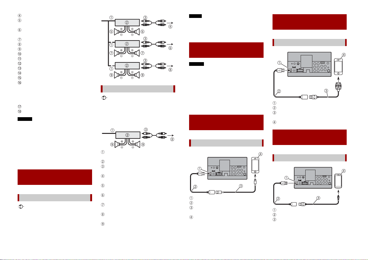
Power amp (sold
separately)
Without internal amp
The speaker leads are not used when this
connection is in use.
With internal amp
Front speaker and Rear speaker signals
(STD) or middle range speaker and high
range speaker signals (NW) are output
from the speaker leads when this
connection is in use.
System remote control
Connect to Blue/white cable.
Power amp (sold separately)
Connect with RCA cable (sold
separately)
To Rear output (STD)
To m idd le r ange o utp ut ( NW )
Rear speaker (STD)
Middle range speaker (NW)
To Front output (STD)
To high range output (NW)
Fron t speaker (S TD)
High range speaker (NW)
To subwoofer output (STD)
To l ow r ange o utp ut ( NW )
Subwoofer (STD)
Low range speaker (NW)
Select the appropriate speaker mode
between stan dard mode (STD) and
network mode (NW). For details, refer to
the Operation Manual.
iPod/iPhone and
smartphone
• For d etails on how to connect an ex ternal
device using a separately sold cable, refer
to the manual for the cable.
• For details concerning the connection,
operations and compatibility of iPhone,
refer to the Operation Manual.
• For details concerning the connection
and operations of smartphone, refer to
the Operation Manual.
iPod/iPhone with
Lightning connector
Connecting via the USB port
USB port
USB cable 1.5 m (4 ft. 11 in.)
USB interface cable for iPod/iPhone (CD-
IU52) (sold separately)
iPhone with Lightning connector
iPhone with 30-pin
connector
Connecting via the USB port
USB port
USB cable 1.5 m (4 ft. 11 in.)
USB interface cable for iPod/iPhone (CD-
IU51) (sold separately)
iPhone with 30-pin connector
Smartphone (Android™
device)
Connecting via the USB port
USB port
USB cable 1.5 m (4 ft. 11 in.)
USB - micro USB cable (Type USB A -
micro USB B) (supplied with CD-MU200
(sold separately))
4En
English
USB Type-C cable (Type USB A - USB C)
NOTE
WARNIN G
CAUTION
NOTES
NOTE
WARNIN G
(supplied with CD-CU50 (sold
separately))
Smartphone
The length of Type USB A - micro USB B
cable cannot exceed 2 m (6 ft. 6 in.) and
Type USB A - USB C cannot exceed 4 m (13
ft. 1 in.) according to the USB cable
standard. When using a cable other than
the above conditions, the main unit
function may not operate properly.
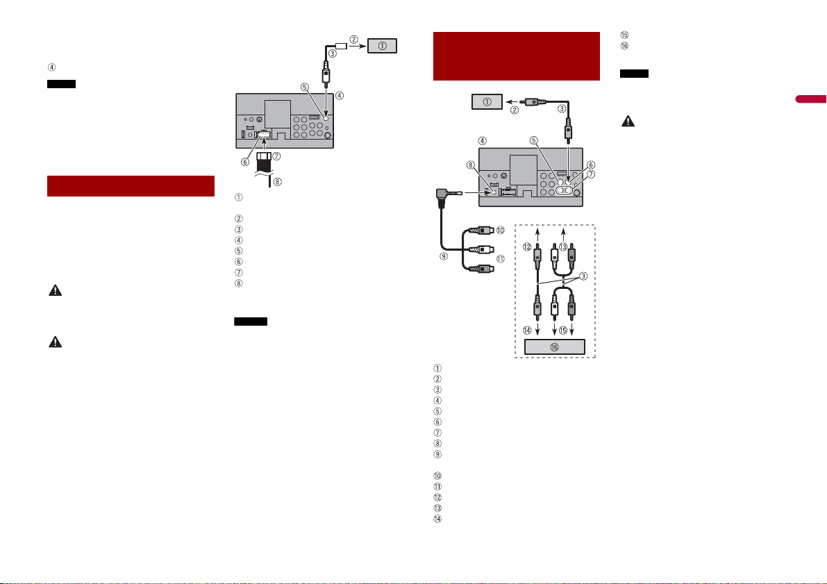
Camera
About rear view camera
When you use the rear view camera, the
rear view image is automatically switched
from the video by moving the shift lever to
REVERSE (R). Camera View mode also
allows you to check what is behind you
while driving.
USE INPUT ONLY FOR REVERSE OR MIRROR
IMAGE REAR VIEW CAMERA. OTHER USE
MAY RESULT IN INJURY OR DAMAGE.
• The screen image may appear reversed.
• With the rear view camera you can keep
an eye on trailers, or back into a tight
parking spot. Do not use for
entertainment purposes.
• Object s in rear view may appear closer or
more distant than in reality.
• The image area of full-screen images
displayed while backing or checking the
rear of the vehicle may differ slightly.
Rear view camera (ND-BC8) (sold
separately)
To v ide o ou tpu t
RCA cable (supplied with ND-BC8)
This product
Brown (R.C IN)
Power supply
Power cord
Violet/white (REVERS E-GEAR SIGNAL
INPUT)
Refer to Power cord on page 3.
• Connec t only the rear view camera to R.C
IN. Do not connect any other equipment.
• Some appropriate settings are required
to use rear view came ras. For details, refer
to the Operation Manual.
External video
component and the
display
Rear display with RCA input jacks
To v ide o in put
RCA cables (sold separately)
This product
Yel low (V IN)
Yel low (V OUT)
Red, white (R IN, L IN)
AUX input
Mini-jack AV cable (CD-RM10) (sold
separately)
Yel low
Red, white
To Yellow
To Red, white
To v ide o ou tpu t
To a udi o ou tpu ts
External video component (sold
separately)
The appropriate setting is required to use
the external video component. For details,
refer to the Operation Manual.
NEVER install the rear display in a
location that enables the driver to watch
the video s ource while driving.
This product’s rear video output is for
connection of a display to enable
passengers in the rear seats to watch the
video source.
5En
CAUTION
Installation
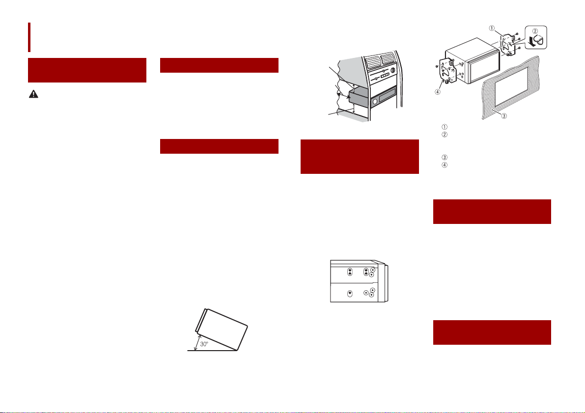
Leave ample
space
5 cm
5 cm
sure you leave ample space behind the
rear panel and wrap any loose cables so
they are not blocking the vents.
Precautions before
installation
Never install this product in places where,
or in a manner that:
• Could injure the driver or passengers if
the vehicle stops suddenly.
• M ay interfere with the driver’s operation
of the vehicle, such as on the floor in front
of the driver’s seat, or close to the
steering wheel or shift lever.
• To ensure proper installation, be sure to
use the supplied parts in the manner
specified. If any parts are not supplied
with this product, use compatible parts in
the manner specified after you have the
part compatibility checked by your
dealer. If parts other than supplied or
compatible ones are used, they may
damage internal parts of this product or
they may work loose and the product
may become detached.
• Do not install this product where it may
(i) obstruct the driver’s vision,
(ii) impair the performance of any of the
vehicle’s operating systems or safety
features, including airbags, hazard lamp
buttons or
(iii) impair the driver’s ability to safely
operate the vehicle.
• Never install this product in front of or
next to the place in the dashboard, door,
or pillar from which one of your vehicle’s
airbags would de ploy. Please refer to your
vehicle’s owner’s manual for reference to
the deployment area of the frontal
airbags.
Before installing
• Consult with your nearest dealer if
installation requires drilling holes or
other modification s of the vehicle.
• Before making a final installation of this
product, temporarily connect the wiring
to confirm that the connections are
correct and the system works properly.
Installation notes
• Do not install this product in places
subject to high temperatures or
humidity, such as:
– Places close to a heater, vent or air
conditioner.
– Places exposed to direct sunlight, such
as on top of the dashboard.
– Places that may be exposed to rain,
such as close to the door or on the
vehicle’s floor.
• Install this product horizontally on a
surface within 0 to 30 degrees tolerance
(within 5 degrees to the left or right).
Improper installation of the unit with the
surface tilted more than these tolerances
increases the potential for errors in the
vehicle’s location display, and might
otherwise cause reduced display
perfor mance.
• When installing, to ensure proper heat
dispersal when using this product, make
Installation using the
screw holes on the side
of this product
1 Fastening this product to the factory
radio-m ounting bracket.
Position this product so that its screw
holes are aligned with the screw holes
of the brack et, and tighten the sc rews at
three locations on each side.
Use either the truss head screws (5 mm
× 8 mm) or flush surface screws (5 mm ×
9 mm), depending on the shape of the
bracket’s screw holes.
Fac tor y rad io- moun ting b rack et
If the pawl interferes with
installation, you may bend it down
out of the way.
Dashboard or console
Truss head screw or flush surface
screw
Be sure to use the screws supplied
with this product.
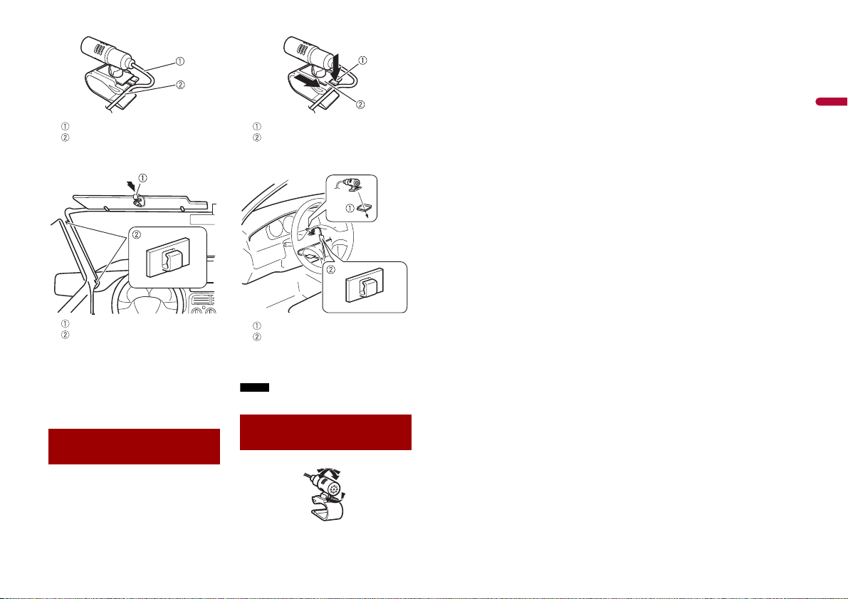
Installing the
microphone
• Install the microphone in a place where
its direction and distance from the driver
make it easiest to pick up the driver’s
voice.
• Be sure to turn off (ACC OFF) the product
before connecting the microphone.
• Depending on the vehicle model, the
microphone cable length may be too
short when you mount the microphone
on the sun visor. In such cases, install the
microphone on the steering column.
Mounting on the sun
visor
1 Fit the microphone lead into the
groove.
6En
English
Microphone lead
NOTE
Groove
2 Attach the microphone clip to the sun
visor.
Tab
Microphone base
2 Mount the microphone on the
steering column.
Microphone clip
Clamps
Use separately sold clamps to secure
the lead where necessary inside the
vehicle .
Install the microphone on the sun visor
when it is in the up position. It cannot
recognise the driver’s voice if the sun
visor is in the down position.
Installation on the
steering column
1 Detach the microphone base from the
microphone clip by sliding the
microphone base while pressing the
tab.
Double-sided tape
Clamps
Use separately sold clamps to secure
the lead where necessary inside the
vehicle.
Keeping it away from the steering wheel.
Adjusting the
microphone angle
7En

ATT ENTI ON
ATT ENTI ON
PRÉCAUTION
Connexion
ATT ENTI ON
Précautions
Votre nouveau produit et ce
manuel
• N’utilisez pas ce produit, les applications
ou la caméra de recul en option (le cas
échéant) si cela vous distrait de quelque
façon affectant l’utilisation sécuritaire de
votre véhicule. Respectez toujours les
règles de conduite sécuritaire et toute la
réglementation routière en vigueur. Si
vous avez du mal à utiliser ce produit ou à
voir l’affichage, stationnez votre véhicule
dans un emplacement sûr et engagez le
frein de stationnement avant d’effectuer
les réglages nécessaires.
• N’installez pas ce produit là où il risque
(i) de gêner la vision du conducteur,
(ii) d’affecter le fonctionnement de tout
système ou de tout dispositif de sécurité
du véhicule, y compris les coussins de
sécurité gonflables ou les boutons de
feux de détresse, ou
(iii) d’affecter la capacité du conducteur à
utiliser le véhicule de façon sécuritaire.
Dans certains cas, il peut être impossible
d’installer ce produit en raison du type de
véhicule ou de la forme de l’intérieur du
véhicule.
Importantes mesures
de protection
Pioneer ne recommande pas d’installer ce
produit soi-même. Ce produit est conçu
pour être installé uniquement par des
professionnels. Il est recommandé de
confier la configuration et l’installation de
ce produit au personnel de service de
Pioneer uniquement, qui a reçu une
formation spéciale et a l’expérience des
appareils électroniques mobiles. NE
RÉPAREZ JAMAIS CE PRODUIT VOUS MÊME. En installant ou réparant vousmême ce produit et ses câbles de
connexion, vous vous exposez à un risque
de décharge électrique ou d’autres
dangers et vous risquez de causer des
dommages non couverts par la garantie à
ce produit.
Précautions à prendre
avant de connecter le
système
Ne faites rien pour trafiquer ou désactiver
le dispositif d’interverrouillage du frein de
stationnement, mis en place pour assurer
votre protection. Trafiquer ou désactiver le
dispositif d’interverrouillage du frein de
stationnement peut entraîner une blessure
grave ou le décès.
• Fixez tous les câbles avec des serre-câbles
ou du ruban isolant. Ne laissez aucun fil
nu exposé.
• Ne connectez pas le fil jaune de ce
produit directement à la batterie du
véhicule. Si le fil est directement
connecté à la batterie, les vibrations du
moteur peuvent éventuellement
endommager l’isolation au point où le fil
passe de l’habitacle au compartiment
moteur. Si l’isolation du fil jaune s’use au
contact des pièces métalliques, cela peut
causer un court-circuit très dang ereux.
• Il est extrêmement dangereux de laisser
les câbles s’enrouler autour de la colonne
de direction ou du levier de vitesse.
Assurez-vous d’installer ce produit, ses
câbles et ses fils à l’écart, de sorte qu’ils ne
gênent pas la conduite.
• Assurez-vous que les câbles et fils ne
gêneront pas ou ne seront pas coincés
par les pièces mobiles du véhicule, et tout
particulièrement le volant de direction, le
levier de vitesse, le frein de
stationnement, les rails de siège
coulissant, les portières ou toute
commande du véhicule.
• Ne posez pas les fils à des emplacements
exposés à des températures élevées. La
surchauffe de l’isolation peut
endommager les fils, entraînant un courtcircuit ou un problème de
fonctionnement et des dommages
permanents au produit.
• Ne raccourcissez aucun fil. Autrement, le
circuit de protection (porte-fusible,
résistance de protection ou filtre, etc.)
risque de ne pas bien fonctionner.
• N’alimentez jamais d’autres produits
électroniques en coupant l’isolation du fil
d’alimentation de ce produit pour y
connecter un autre fil. La capacité du fil
serait dépassée, entraînant une
surchauffe.
Avant d’installer ce
produit
• N’utilisez cet appareil qu’avec une
batterie 12 volts avec masse négative.
Autrement, il y a risque d’incendie ou de
problème de foncti onnement.
• Pour éviter de court-circuiter le système
électrique, pensez à déconnecter le câble
de batterie (–) avant l’installation.
Pour éviter les
dommages
• Lorsque la sortie de haut-parleur est
utilisée par 4 canaux, utilisez des hautparleurs de plus de 50 W (Puissance
d’entrée maximale) et de 4 Ω à 8 Ω (valeur
d’impédance). N’utilisez pas de hautparleurs de 1 Ω à 3 Ω avec cet appareil.
• Lorsque la sortie de haut-parleur arrière
est utilisée par un caiss on d’ex trêmes
graves de 2 Ω, utilisez des haut-parleurs
de plus de 70 W (Puissance d’entrée
maximale ).
*Veuillez vous reporter aux connexions
pour connaître la méthode de connexion.
• Le câble noir est le câble de masse. Lors
de l’installation de cet appareil ou d’un
amplificateur de puissance (vendu
séparément), pensez à connecter d’abord
le fil de masse. Assurez-vous que le fil de
masse est bien connecté à une partie
métallique de la carrosserie du véhicule.
Le fil de masse de l’amplificateur de
puissance et celui de cet appareil ou de
tout autre dispositif doivent être
connectés au véhicule séparément, avec
des vis différentes. Si la vis d u fil de masse
se desserre ou tombe, il y a risque
d’incendie et de génération de fumée ou
de problème de fonctionnement.
2Fr
 Loading...