


 Loading...
TOYOTA
ORDER NO.
CRT3254
FH-M8047ZT/XN/ES
HEAD UNIT
FH-M8047ZT/XN/ES
FH-M8047ZT/XIN/ES
FH-M8147ZT/XN/ES
FH-M8147ZT/XIN/ES
This service manual should be used together with the following manual(s):
Model No. |
|
Order No. |
Mech.Module |
|
Remarks |
|
|||
|
|
|
|
|
|
|
|
|
|
CX-3057 |
|
CRT3026 |
S10MP3 |
|
CD Mech. Module:Circuit Description, Mech. Description, Disassembly |
||||
|
|
|
|
|
|
|
|
|
|
CX-1011 |
|
CRT2406 |
3L |
|
CD Mech. Module:Mech. Description, Disassembly |
|
|||
|
|
|
|
|
|
|
|
|
|
|
|
|
|
|
|
|
|
|
|
VEHICLE |
|
DESTINATION |
PRODUCED |
OEM PARTS No. |
ID No. |
|
PIONEER MODEL No. |
||
|
AFTER |
|
|||||||
|
|
|
|
|
|
|
|
||
|
|
|
|
|
|
|
|
||
|
INDONESIA |
|
APRIL 2005 |
86120-0K140 |
P7836 |
|
FH-M8047ZT/XN/ES |
||
|
|
|
|
|
|
|
|
||
|
INDONESIA |
|
AUGUST 2004 |
86120-0K120 |
P7832 |
|
FH-M8047ZT/XIN/ES |
||
|
|
|
|
|
|
|
|||
|
GULF COOPERATION COUNCIL |
JULY 2005 |
86120-0K100 |
P7837 |
|
FH-M8147ZT/XN/ES |
|||
|
|
|
|
|
|
|
|||
|
GULF COOPERATION COUNCIL |
JULY 2005 |
86120-0K060 |
P7833 |
|
FH-M8147ZT/XIN/ES |
|||
|
|
|
|
|
|
|
|
|
|
Dolby noise reduction manufactured under license from Dolby Laboratories Licensing Corporation.
"Dolby" and the double-D symbol are trademarks of Dolby Laboratories Licensing Corporation.
For details, refer to "Important symbols for good services".
PIONEER CORPORATION 4-1, Meguro 1-chome, Meguro-ku, Tokyo 153-8654, Japan
PIONEER ELECTRONICS (USA) INC. P.O. Box 1760, Long Beach, CA 90801-1760, U.S.A.
PIONEER EUROPE NV Haven 1087, Keetberglaan 1, 9120 Melsele, Belgium
PIONEER ELECTRONICS ASIACENTRE PTE. LTD. 253 Alexandra Road, #04-01, Singapore 159936
 PIONEER CORPORATION 2004
K-ZZD.JUNE 2004 printed in Japan
1 |
2 |
3 |
4 |
SAFETY INFORMATION
This service manual is intended for qualified service technicians; it is not meant for the casual do-it-yourselfer. Qualified technicians have the necessary test equipment and tools, and have been trained to properly and safely
Arepair complex products such as those covered by this manual.
Improperly performed repairs can adversely affect the safety and reliability of the product and may void the warranty. If you are not qualified to perform the repair of this product properly and safely, you should not risk trying to do so and refer the repair to a qualified service technician.
- Service Precaution 
1.You should conform to the regulations governing the product (safety, radio and noise, and other regulations), and should keep the safety during servicing by following the safety instructions
B
described in this manual.
2.Before disassembling the unit, be sure to turn off the power. Unplugging and plugging the connectors during power-on mode may damage the ICs inside the unit.
3.To protect the pickup unit from electrostatic discharge during servicing, take an appropriate treatment (shorting-solder) by referring to "the DISASSEMBLY" on page 72.
4.After replacing the pickup unit, be sure to check the grating. (See page 63.)
C
[ Important symbols for good services ]
In this manual, the symbols shown-below indicate that adjustments, settings or cleaning should be made securely. When you find the procedures bearing any of the symbols, be sure to fulfill them:
1. Product safety
You should conform to the regulations governing the product (safety, radio and noise, and other regulations), and should keep the safety during servicing by following the safety instructions described in this manual.
2. Adjustments
D |
To keep the original performances of the product, optimum adjustments or specification confirmation is indispensable. |
|
In accordance with the procedures or instructions described in this manual, adjustments should be performed. |
||
|
3. Cleaning
For optical pickups, tape-deck heads, lenses and mirrors used in projection monitors, and other parts requiring cleaning, proper cleaning should be performed to restore their performances.
4. Shipping mode and shipping screws
To protect the product from damages or failures that may be caused during transit, the shipping mode should be set or the shipping screws should be installed before shipping out in accordance with this manual, if necessary.
E
5. Lubricants, glues, and replacement parts
Appropriately applying grease or glue can maintain the product performances. But improper lubrication or applying
 glue may lead to failures or troubles in the product. By following the instructions in this manual, be sure to apply the
 prescribed grease or glue to proper portions by the appropriate amount.For replacement parts or tools, the prescribed ones should be used.
F
2 |
|
FH-M8047ZT/XN/ES |
|
|
1 |
2 |
|
3 |
4 |

5 |
6 |
7 |
8 |
CONTENTS |
|
|
|
SAFETY INFORMATION...................................................................................................................................... |
|
|
2 |
1. SPECIFICATIONS ............................................................................................................................................. |
|
|
4 |
2. EXPLODED VIEWS AND PARTS LIST............................................................................................................. |
|
|
6 |
2.1 EXTERIOR(FH-M8047ZT/XN/ES,FH-M8047ZT/XIN/ES)........................................................................... |
|
6 |
|
2.2 EXTERIOR(FH-M8147ZT/XN/ES,FH-M8147ZT/XIN/ES)........................................................................... |
|
8 |
|
2.3 CD MECHANISM MODULE ..................................................................................................................... |
|
|
10 |
2.4 CASSETTE MECHANISM MODULE ....................................................................................................... |
|
|
12 |
3. BLOCK DIAGRAM AND SCHEMATIC DIAGRAM .......................................................................................... |
|
14 |
|
3.1 BLOCK DIAGRAM.................................................................................................................................... |
|
|
14 |
3.2 OVERALL CONNECTION DIAGRAM(GUIDE PAGE) .............................................................................. |
|
16 |
|
3.3 KEYBOARD UNIT(FH-M8047ZT/XN/ES,FH-M8047ZT/XIN/ES).............................................................. |
|
22 |
|
3.4 KEYBOARD UNIT(FH-M8147ZT/XN/ES,FH-M8147ZT/XIN/ES).............................................................. |
|
24 |
|
3.5 CD MECHANISM MODULE(GUIDE PAGE) ............................................................................................. |
|
26 |
|
3.6 CASSETTE MECHANISM MODULE ....................................................................................................... |
|
|
36 |
4. PCB CONNECTION DIAGRAM ...................................................................................................................... |
|
|
38 |
4.1 MAIN UNIT ............................................................................................................................................... |
|
|
38 |
4.2 KEYBOARD UNIT(FH-M8047ZT/XN/ES,FH-M8047ZT/XIN/ES).............................................................. |
|
42 |
|
4.3 KEYBOARD UNIT(FH-M8147ZT/XN/ES,FH-M8147ZT/XIN/ES).............................................................. |
|
44 |
|
4.4 CD MECHANISM MODULE ..................................................................................................................... |
|
|
46 |
4.5 DECK UNIT .............................................................................................................................................. |
|
|
48 |
4.6 SENSOR UNIT ......................................................................................................................................... |
|
|
49 |
5. ELECTRICAL PARTS LIST ............................................................................................................................. |
|
|
50 |
6. ADJUSTMENT ................................................................................................................................................ |
|
|
60 |
6.1 CONNECTION DIAGRAM........................................................................................................................ |
|
|
60 |
6.2 TEST MODE ............................................................................................................................................. |
|
|
60 |
6.3 CD ADJUSTMENT ................................................................................................................................... |
|
|
61 |
6.4 CHECKING THE GRATING AFTER CHANGING THE PICKUP UNIT..................................................... |
|
63 |
|
6.5 DOLBY B NR ADJUSTMENT................................................................................................................... |
|
|
66 |
6.6 AVC-LAN DIAGNOSIS MODE.................................................................................................................. |
|
|
67 |
7. GENERAL INFORMATION ............................................................................................................................. |
|
|
72 |
7.1 DIAGNOSIS.............................................................................................................................................. |
|
|
72 |
7.1.1 DISASSEMBLY...................................................................................................................................... |
|
|
72 |
7.1.2 CONNECTOR FUNCTION DESCRIPTION .......................................................................................... |
|
76 |
|
7.2 PARTS ...................................................................................................................................................... |
|
|
77 |
7.2.1 IC ........................................................................................................................................................... |
|
|
77 |
7.2.2 DISPLAY................................................................................................................................................ |
|
|
83 |
7.3 OPERATIONAL FLOW CHART ................................................................................................................ |
|
|
84 |
7.4 CLEANING ............................................................................................................................................... |
|
|
85 |
8. OPERATIONS ................................................................................................................................................. |
|
|
86 |
A
B
C
D
E
F
|
|
|
|
|
|
|
|
|
|
FH- |
M8047ZT/XN/ES |
|
|
3 |
|
5 |
6 |
|
|
|
7 |
8 |
|
|
|
||||||
1 |
2 |
3 |
4 |
A
BSystem……………………… Compact disc audio system Usable discs………………………………… Compact disc Signal format
Sampling frequency…………………………… 44.1 kHz Number of quantization bits……………………16; linear Number of channels …………………………… 2 (stereo)
MP3 decoding format
…………………… MPEG1 & 2 Audio Layer 3 Distortion …………………………………… 0.3 % or less S / N ……………………………………… 65 dB or more Stereo separation ………………………… 60 dB or more
Cassette player
C
D
E
F
4 |
|
FH-M8047ZT/XN/ES |
|
|
1 |
2 |
|
3 |
4 |

5 |
6 |
7 |
8 |
A
B
C
D
E
F
|
|
|
|
|
|
|
|
|
|
FH- |
M8047ZT/XN/ES |
|
|
5 |
|
5 |
6 |
|
|
|
7 |
8 |
|
|
|
||||||
1 2 3 4
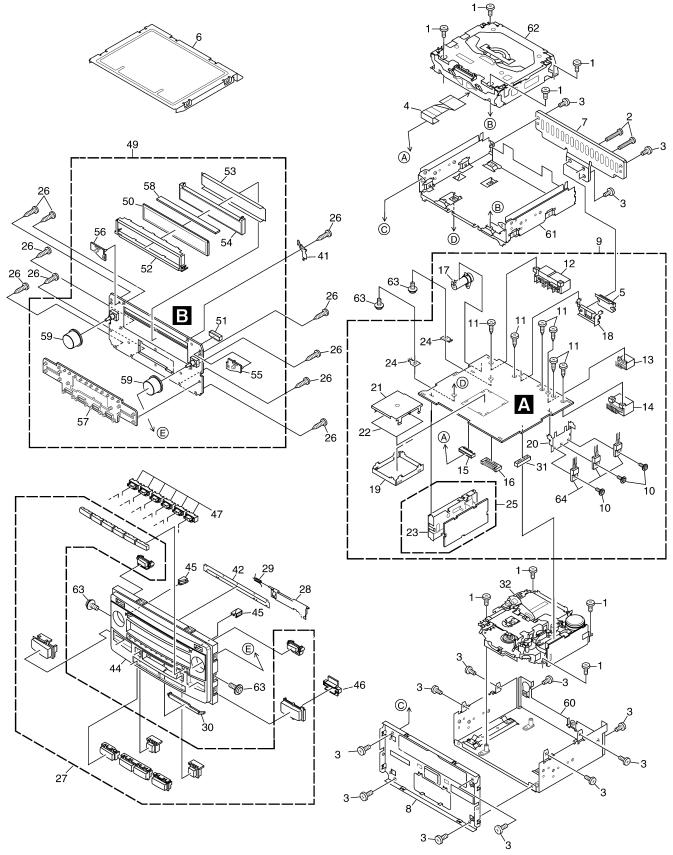
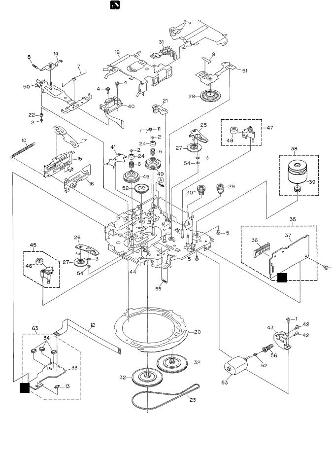
2. EXPLODED VIEWS AND PARTS LIST
NOTES : • Parts marked by " * " are generally unavailable because they are not in our Master Spare Parts List.
A |
• Screw adjacent to"mark on the product are used for disassembly. |
|
• For the applying amount of lobricants or glue, follow the instructions in this manual. |
||
|
||
|
(In the case of no amount instructions,apply as you think it appropriate.) |
|
|
2.1 EXTERIOR(FH-M8047ZT/XN/ES,FH-M8047ZT/XIN/ES) |
B
C
D
E
F
6 |
|
FH-M8047ZT/XN/ES |
|
|
1 |
2 |
|
3 |
4 |

|
5 |
6 |
|
7 |
8 |
(1) EXTERIOR SECTION PARTS LIST(FH-M8047ZT/XN/ES,FH-M8047ZT/XIN/ES) |
|
||||
Mark No. |
Description |
Part No. |
Mark No. |
Description |
Part No. |
1 |
Screw |
BSZ26P060FTC |
|
|
|
2 |
Screw |
BSZ26P140FTC |
31 |
Connector(CN631) |
CKS3568 |
3 |
Screw |
BSZ30P080FTC |
32 |
Cassette Mechanism Module |
See Contrast table(2) |
4 |
Connector |
CDE7172 |
33 |
••••• |
|
5 |
IC(IC801) |
TDA7386 |
34-40 |
••••• |
|
|
|
|
41 |
Earth Plate |
CND1990 |
6 |
Case |
CNB2937 |
|
|
|
7 |
Heat Sink |
CNC9594 |
42 |
Cover |
CNM7433 |
8 |
Frame |
CND2439 |
43 |
••••• |
|
9 |
Main Unit |
CWM9213 |
44 |
Grille |
See Contrast table(2) |
10 |
Screw |
ASZ26P080FTC |
45 |
Lighting Conductor |
CNV7939 |
|
|
|
46 |
Holder |
CNV7946 |
11 |
Screw |
BPZ30P060FSN |
|
|
|
12 |
Connector(CN471) |
CKM1222 |
47 |
Holder |
CNV8015 |
13 |
Connector(CN473) |
CKM1350 |
48 |
••••• |
|
14 |
Connector(CN472) |
CKM1351 |
49 |
Keyboard Unit |
CWM9216 |
15 |
Connector(CN601) |
CKS3837 |
50 |
LCD |
CAW1826 |
|
|
|
51 |
Connector(CN901) |
CKS4574 |
16 |
Connector(CN479) |
CKS4573 |
|
|
|
17 |
86146-48030(CN501) |
CKX1057 |
52 |
Holder |
CND1989 |
18 |
Holder |
CNC9592 |
53 |
Sheet |
CNM8601 |
19 |
Shield |
CNC9595 |
54 |
Lighting Conductor |
CNV7938 |
20 |
Holder |
CND1080 |
55 |
Rubber |
CNV7942 |
|
|
|
56 |
Rubber |
CNV7943 |
21 |
Shield |
CND1118 |
|
|
|
22 |
Insulator |
CNM7823 |
57 |
Rubber |
CNV7944 |
23 |
Holder |
CNC8855 |
58 |
Connector |
CNV7947 |
24 |
Terminal(CN474,475) |
VNF1084 |
59 |
Knob Unit |
CXC3300 |
25 |
FM/AM Tuner Unit |
CWE1557 |
60 |
Chassis Unit |
CXC2495 |
|
|
|
61 |
Chassis Unit |
CXC2856 |
26 |
Screw |
BPZ20P080FTC |
|
|
|
27 |
Button Unit |
CXC4309 |
62 |
CD Mechanism Module S10MP3TOYOTACXK5681 |
|
28 |
Door |
CAT2535 |
63 |
Screw |
ISS26P055FTC |
29 |
Spring |
CBH1371 |
64 |
Transistor(Q431,441,851) |
2SB1185 |
30 |
Lighting Conductor |
CNV7941 |
|
|
|
A
B
C
D
(2) CONTRAST TABLE
FH-M8047ZT/XN/ES and FH-M8047ZT/XIN/ES are constructed the same except for the following:
Mark |
NO |
Description |
FH-M8047ZT/XN/ES |
FH-M8047ZT/XIN/ES |
|
|
|
|
|
|
32 |
Cassette Mechanism Module |
EXK4282 |
EXK4280 |
|
44 |
Grille |
CNS7980 |
CNS7728 |
E
F
|
|
|
|
|
|
|
|
|
|
FH- |
M8047ZT/XN/ES |
|
|
7 |
|
5 |
6 |
|
|
|
7 |
8 |
|
|
|
||||||
1 |
2 |
3 |
4 |
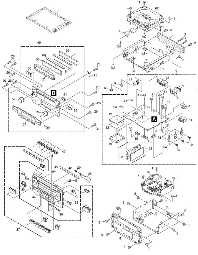
2.2 EXTERIOR(FH-M8147ZT/XN/ES,FH-M8147ZT/XIN/ES)
A
B
C
D
E
F
8 |
|
FH-M8047ZT/XN/ES |
|
|
1 |
2 |
|
3 |
4 |

|
5 |
6 |
|
7 |
8 |
(1) EXTERIOR SECTION PARTS LIST(FH-M8147ZT/XN/ES,FH-M8147ZT/XIN/ES) |
|
||||
Mark No. |
Description |
Part No. |
Mark No. |
Description |
Part No. |
1 |
Screw |
BSZ26P060FTC |
|
|
|
2 |
Screw |
BSZ26P140FTC |
31 |
Connector(CN631) |
CKS3568 |
3 |
Screw |
BSZ30P080FTC |
32 |
Cassette Mechanism Module |
See Contrast table(2) |
4 |
Connector |
CDE7172 |
33 |
Holder |
CNV7946 |
5 |
IC(IC801) |
TDA7386 |
34-40 |
••••• |
|
|
|
|
41 |
Earth Plate |
CND1990 |
6 |
Case |
CNB2937 |
|
|
|
7 |
Heat Sink |
CNC9594 |
42 |
Cover |
CNM7433 |
8 |
Frame |
CND2439 |
43 |
••••• |
|
9 |
Main Unit |
CWM9213 |
44 |
Grille |
See Contrast table(2) |
10 |
Screw |
ASZ26P080FTC |
45 |
Lighting Conductor |
CNV7939 |
|
|
|
46 |
••••• |
|
11 |
Screw |
BPZ30P060FSN |
|
|
|
12 |
Connector(CN471) |
CKM1222 |
47 |
Holder |
CNV8015 |
13 |
Connector(CN473) |
CKM1350 |
48 |
••••• |
|
14 |
Connector(CN472) |
CKM1351 |
49 |
Keyboard Unit |
CWM9364 |
15 |
Connector(CN601) |
CKS3837 |
50 |
LCD |
CAW1826 |
|
|
|
51 |
Connector(CN901) |
CKS4574 |
16 |
Connector(CN479) |
CKS4573 |
|
|
|
17 |
86146-48030(CN501) |
CKX1057 |
52 |
Holder |
CND1989 |
18 |
Holder |
CNC9592 |
53 |
Sheet |
CNM8601 |
19 |
Shield |
CNC9595 |
54 |
Lighting Conductor |
CNV7938 |
20 |
Holder |
CND1080 |
55 |
Rubber |
CNV7942 |
|
|
|
56 |
Rubber |
CNV7943 |
21 |
Shield |
CND1118 |
|
|
|
22 |
Insulator |
CNM7823 |
57 |
Rubber |
CNV7944 |
23 |
Holder |
CNC8855 |
58 |
Connector |
CNV7947 |
24 |
Terminal(CN474,475) |
VNF1084 |
59 |
Knob Unit |
CXC3300 |
25 |
FM/AM Tuner Unit |
CWE1557 |
60 |
Chassis Unit |
CXC2495 |
|
|
|
61 |
Chassis Unit |
CXC2856 |
26 |
Screw |
BPZ20P080FTC |
|
|
|
27 |
Button Unit |
CXC4310 |
62 |
CD Mechanism Module S10MP3TOYOTACXK5681 |
|
28 |
Door |
CAT2535 |
63 |
Screw |
ISS26P055FTC |
29 |
Spring |
CBH1371 |
64 |
Transistor(Q431,441,851) |
2SB1185 |
30 |
Lighting Conductor |
CNV7941 |
|
|
|
A
B
C
D
(2) CONTRAST TABLE
FH-M8147ZT/XN/ES and FH-M8147ZT/XIN/ES are constructed the same except for the following:
Mark |
NO |
Description |
FH-M8147ZT/XN/ES |
FH-M8147ZT/XIN/ES |
|
|
|
|
|
|
32 |
Cassette Mechanism Module |
EXK4282 |
EXK4280 |
|
44 |
Grille |
CNS7981 |
CNS7850 |
E
F
|
|
|
|
|
|
|
|
|
|
FH- |
M8047ZT/XN/ES |
|
|
9 |
|
5 |
6 |
|
|
|
7 |
8 |
|
|
|
||||||
1 |
2 |
3 |
4 |
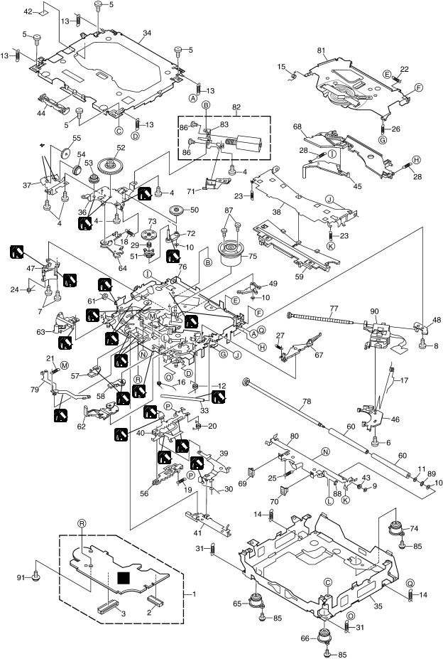
2.3 CD MECHANISM MODULE
A
B 1


|
1 |
1 |
|
2 |
1 |
|
|
C |
|
2 |
1 |
|
|
2 |
1 |
2 |
1 |
|
|
|
1 |
D |
1 |
|
3 |
1
2 |
|
2 |
|
|
|
|
1 |
1 |
|
|
|
|
|
1 |
|
|
1 |
1GEM1024
2GEM1045
3GEM1035
E
C
F
10 |
|
FH-M8047ZT/XN/ES |
|
|
1 |
2 |
|
3 |
4 |
5 |
6 |
CD MECHANISM MODULE SECTION PARTS LIST
Mark No. |
Description |
Part No. |
1 |
CD Core Unit(S10MP3) |
CWX3009 |
2 |
Connector(CN101) |
CKS4182 |
3 |
Connector(CN901) |
CKS4017 |
4 |
Screw |
BMZ20P035FTC |
5 |
Screw |
BSZ20P040FTC |
6 |
Screw(M2x4) |
CBA1362 |
7 |
Screw(M2x3) |
CBA1511 |
8 |
Screw(M2x3) |
CBA1527 |
9 |
Washer |
CBF1037 |
10 |
Washer |
CBF1038 |
11 |
Washer |
CBF1060 |
12 |
Spring |
CBH2390 |
13 |
Spring |
CBH2606 |
14 |
Spring |
CBH2607 |
15 |
Spring |
CBH2608 |
16 |
Spring |
CBH2609 |
17 |
Spring |
CBH2610 |
18 |
Spring |
CBH2611 |
19 |
Spring |
CBH2612 |
20 |
Spring |
CBH2613 |
21 |
Spring |
CBH2614 |
22 |
Spring |
CBH2615 |
23 |
Spring |
CBH2616 |
24 |
Spring |
CBH2617 |
25 |
Spring |
CBH2620 |
26 |
Spring |
CBH2621 |
27 |
Spring |
CBH2641 |
28 |
Spring |
CBH2642 |
29 |
Spring |
CBH2643 |
30 |
Spring |
CBH2659 |
31 |
Spring |
CBH2688 |
32 |
••••• |
|
33 |
Shaft |
CLA4441 |
34 |
Frame |
CNC9962 |
35 |
Frame |
CNC9963 |
36 |
Bracket |
CNC9966 |
37 |
Bracket |
CNC9967 |
38 |
Arm |
CNC9968 |
39 |
Arm |
CNC9973 |
40 |
Lever |
CNC9983 |
41 |
Lever |
CNC9984 |
42 |
Sheet |
CNM8134 |
43 |
Collar |
CNV6906 |
44 |
Guide |
CNV6925 |
45 |
Arm |
CNV7198 |
|
7 |
8 |
Mark No. |
Description |
Part No. |
50 |
Gear |
CNV7207 |
51 |
Gear |
CNV7208 |
52 |
Gear |
CNV7209 |
53 |
Gear |
CNV7210 |
54 |
Gear |
CNV7211 |
55 |
Gear |
CNV7212 |
56 |
Rack |
CNV7214 |
57 |
Arm |
CNV7215 |
58 |
Arm |
CNV7216 |
59 |
Guide |
CNV7217 |
60 |
Roller |
CNV7218 |
61 |
Gear |
CNV7219 |
62 |
Arm |
CNV7221 |
63 |
Arm |
CNV7220 |
64 |
Arm |
CNV7222 |
65 |
Damper |
CNV7634 |
66 |
Damper |
CNV7633 |
67 |
Arm |
CNV7341 |
68 |
Arm |
CNV7342 |
69 |
Guide |
CNV7360 |
70 |
Guide |
CNV7361 |
71 |
Holder |
CNV7437 |
72 |
Arm |
CNV7444 |
73 |
Gear |
CNV7595 |
74 |
Damper |
CNV7632 |
75 |
Motor Unit(M1) |
CXB6007 |
76 |
Chassis Unit |
CXB8728 |
77 |
Screw Unit |
CXB8729 |
78 |
Gear Unit |
CXB8731 |
79 |
Arm Unit |
CXB8732 |
80 |
Arm Unit |
CXC3278 |
81 |
Arm Unit |
CXB8852 |
82 |
Motor Unit(M2) |
CXB8933 |
83 |
Bracket |
CNC9985 |
84 |
••••• |
|
85 |
Screw(M2x5) |
EBA1028 |
86 |
Screw |
JFZ20P020FTC |
87 |
Screw |
JGZ17P022FTC |
88 |
Washer |
YE15FTC |
89 |
Washer |
YE20FTC |
90 |
Pickup Unit(P10)(Service) |
CXX1664 |
91 |
Screw |
IMS26P030FTC |
A
B
C
D
E
46 |
Rack |
CNV7199 |
|
47 |
Holder |
CNV7201 |
F |
48 |
Holder |
CNV7202 |
|
49 |
Arm |
CNV7203 |
|
|
|
|
|
|
|
|
|
|
|
FH- |
M8047ZT/XN/ES |
|
|
11 |
|
5 |
6 |
|
|
|
7 |
8 |
|
|
|
||||||
1 |
2 |
3 |
4 |
2.4 CASSETTE MECHANISM MODULE
For grease application, refer to the service manual for CX-1011 (CRT2406).
A
B
C
D
D
E
E
F
12 |
|
FH-M8047ZT/XN/ES |
|
|
1 |
2 |
|
3 |
4 |

5 |
6 |
7 |
8 |
(1) CASSETTE MECHANISM MODULE SECTION PARTS LIST
Mark No. |
Description |
Part No. |
1 |
Screw |
See Contrast table(2) |
2 |
Washer |
CBF1037 |
3 |
Washer |
CBG1003 |
4 |
Screw |
EBA1028 |
5 |
Screw |
See Contrast table(2) |
6 |
Spring |
EBH1653 |
7 |
Spring |
EBH1642 |
8 |
Spring |
EBH1641 |
9 |
Spring |
EBH1626 |
10 |
Spring |
EBH1627 |
11 |
Spring |
EBH1648 |
12 |
Cord |
EDD1024 |
13 |
Photo-reflector(Q101) |
EGN1004 |
14 |
Arm |
ENC1526 |
15 |
Lever |
ENC1544 |
16 |
Lever |
See Contrast table(2) |
17 |
Arm |
ENC1532 |
18 |
Frame |
ENC1533 |
19 |
Holder |
ENC1534 |
20 |
Gear |
ENC1535 |
21 |
Arm |
ENC1550 |
22 |
Roller |
ENR1040 |
23 |
Belt |
ENT1027 |
24 |
Collar |
ENV1508 |
25 |
Arm |
ENV1539 |
26 |
Arm |
ENV1540 |
27 |
Gear |
ENV1569 |
28 |
Gear |
ENV1547 |
29 |
Gear |
ENV1560 |
30 |
Worm Wheel |
ENV1566 |
31 |
Lever |
ENV1551 |
32 |
Flywheel |
See Contrast table(2) |
Mark No. |
Description |
Part No. |
33 |
Gathering PCB |
ENX1073 |
34 |
Switch(S101,S102,S103) |
ESG1007 |
35 |
Deck Unit |
EWM1040 |
36 |
Plug(CN251) |
CKS3540 |
37 |
Gathering PCB |
ENX1074 |
38 |
Motor Unit(M1) |
EXA1618 |
39 |
Motor |
EXM1035 |
40 |
Head Assy(HD1) |
EXA1594 |
41 |
Arm |
ENC1537 |
42 |
Screw |
See Contrast table(2) |
43 |
Bracket |
ENC1558 |
44 |
Chassis Unit |
See Contrast table(2) |
45 |
Pinch Holder Unit |
EXA1608 |
46 |
Pinch Roller |
ENV1518 |
47 |
Pinch Holder Unit |
EXA1607 |
48 |
Pinch Roller |
ENV1518 |
49 |
Reel Unit |
EXA1625 |
50 |
Head Base Unit |
EXA1611 |
51 |
Lever Unit |
EXA1587 |
52 |
Gear Unit |
EXA1596 |
53 |
Motor Unit(M2) |
See Contrast table(2) |
54 |
Washer |
HBF-179 |
55 |
Spring |
EBH1537 |
56 |
Worm Gear |
ENV1564 |
57 |
••••• |
|
58 |
••••• |
|
59 |
••••• |
|
60 |
••••• |
|
61 |
••••• |
|
62 |
Spring |
EBH1545 |
63 |
Sensor Unit |
EWM1041 |
A
B
C
D
(2) CONTRAST TABLE
FH-M8047ZT/XN/ES, FH-M8147ZT/XN/ES, FH-M8047ZT/XIN/ES and FH-M8147ZT/XIN/ES are constructed the same except for the following:
Mark |
NO |
Description |
FH-M8047ZT/XN/ES |
FH-M8047ZT/XIN/ES |
|
FH-M8147ZT/XN/ES |
FH-M8147ZT/XIN/ES |
||||
|
|
|
|||
|
|
|
|
|
|
|
1 |
Screw |
BSZ20P040FTC |
BSZ20P040FMC |
|
|
5 |
Screw |
EBA1031 |
CBA1037 |
|
|
16 |
Lever |
ENC1531 |
ENC1543 |
|
|
32 |
Flywheel |
ENV1607 |
ENV1554 |
|
|
42 |
Screw |
BMZ20P022FTC |
BMZ20P022FMC |
|
|
44 |
Chassis Unit |
EXA1615 |
EXA1635 |
|
|
53 |
Motor Unit(M2) |
EXA1657 |
EXA1627 |
E
F
|
|
|
|
|
|
|
|
|
|
FH- |
M8047ZT/XN/ES |
|
|
13 |
|
5 |
6 |
|
|
|
7 |
8 |
|
|
|
||||||
1 |
2 |
3 |
4 |
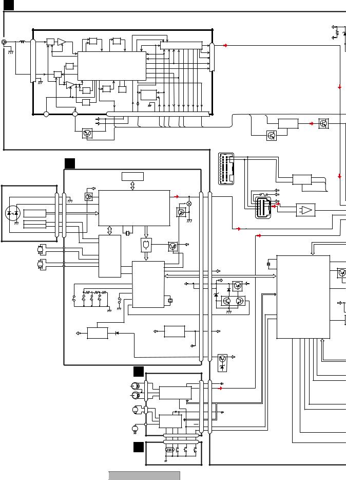
3. BLOCK DIAGRAM AND SCHEMATIC DIAGRAM
3.1 BLOCK DIAGRAM
A |
A MAIN UNIT |
|
|
|
|
|
|
|
|
|
|
|
|
|
|
|
|
|
|
|
|
|
|
|
|
|
|
|
|
|
|
|
|
|
|
|
|
|
||||
|
|
|
|
|
|
|
|
|
|
|
|
|
|
|
|
|
|
|
|
|
|
|
|
|
|
|
|
|
|
|
|
|
|
|
|
|
|
|||||
|
FM/AM TUNER UNIT |
|
|
|
|
|
|
|
|
|
|
|
|
|
|
|
|
|
|
|
|
|
|
|
|
|
|
|
|
|
|
AUDIO+B |
||||||||||
|
CN501 |
|
|
|
AMRF |
FM/AM 1ST IF 10.7MHz |
|
|
|
|
MPXREF 41kHz |
|
|
|
|
|
|
|
|
|
|
|
|
|
|
|
|
|
|
|
|
|
|
|||||||||
|
|
|
|
|
T51 Q51 CF51 |
CF52 CF53 |
|
|
|
AMDET |
|
|
|
|
|
|
|
|
|
|
|
|
|
|
|
|
|
|
|
|
|
1/2VCC |
||||||||||
|
1 |
AMANT |
|
|
|
|
|
|
|
|
|
|
|
|
|
|
|
|
|
|
|
|
|
|
|
|
|
|
|
|
|
|
|
|
|
|
|
|||||
ANTENNA |
ATT |
|
|
|
|
|
|
|
|
|
|
|
|
|
|
|
|
|
|
|
|
|
|
|
|
|
|
|
|
|
|
|
|
|
|
|
|
|
|
|||
28 |
|
|
|
|
|
|
|
|
|
|
|
|
|
|
|
|
|
|
|
|
|
|
|
|
|
|
|
|
L ch |
|
FM L |
|
|
|
|
|
|
|
|
|
||
JACK |
|
|
|
|
|
|
|
|
|
|
|
|
|
|
|
|
|
|
|
|
|
IC 2 FM MPX |
|
|
6 |
|
|
|
|
|
|
|
|
|
||||||||
2 |
|
|
|
|
|
|
|
|
|
|
|
|
|
|
|
|
|
|
|
|
|
|
|
|
|
|
|
|
|
|
|
|
|
|
||||||||
|
|
|
|
|
|
|
|
|
|
|
|
|
|
|
|
|
|
|
|
|
|
|
|
|
|
|
|
|
|
|
R ch |
5 |
|
|
|
|
|
|
|
|
|
|
|
|
|
|
|
|
|
|
|
|
|
|
|
|
|
|
|
|
|
|
|
|
|
|
|
|
|
|
|
|
|
|
|
|
|
|
|
|
|
|
|
|
|
|
|
|
|
|
|
|
|
|
|
|
|
|
|
|
|
|
|
|
|
|
|
|
|
|
|
|
|
|
|
AMIN |
20 |
|
|
|
|
|
|
|
|
|
||
|
|
|
|
|
|
|
|
|
|
|
|
|
|
|
|
|
|
|
|
|
|
|
|
|
|
|
|
|
|
|
|
|
|
|
|
|
|
|
|
|
||
|
|
|
|
|
|
ANT ADJ |
|
|
|
IC1 |
|
|
|
|
|
|
|
|
|
|
|
|
|
|
|
|
|
COMP 21 |
|
|
|
|
|
|
|
|
|
|
||||
|
|
|
|
|
|
|
|
|
MIXER, IF AMP, DET. |
|
|
|
|
|
|
|
|
|
|
|
|
|
|
|
LDET |
18 |
|
|
|
|
|
|
|
|
|
|
||||||
|
27 |
FMANT |
|
ATT |
|
|
|
|
|
|
|
|
|
|
|
|
|
|
|
|
|
|
|
|
|
|
|
|
|
|
|
|
|
|
|
|
|
|
|
|
|
|
|
|
|
|
|
|
|
|
|
|
|
|
|
|
|
|
|
|
|
|
|
|
|
|
|
|
|
|
|
|
|
|
|
|
|
|
|
|
|
|
|
||
|
26 RFGND |
|
|
FMRF |
|
|
|
|
|
|
|
|
|
|
|
|
|
|
|
|
|
|
|
|
|
|
|
|
|
|
|
|
|
|
|
|
|
|
|
|||
B |
|
|
|
|
|
|
|
|
|
CF202 |
|
|
|
|
|
|
|
|
|
|
|
|
|
|
|
|
|
|
|
|
|
|
|
|
|
|
|
|
|
|
|
|
|
|
|
|
|
|
|
|
|
|
|
|
|
|
|
|
|
|
|
|
|
|
|
|
|
|
|
|
|
|
|
|
|
|
|
|
|
|
|
|
|
|
|
|
|
|
|
|
|
|
|
IMG ADJ |
AM 2ND IF X901 |
|
|
|
IC 3 |
|
|
|
|
|
|
|
|
|
|
|
|
|
|
|
|
|
|
|
|
|
|
|
||||||
|
|
|
|
|
|
|
|
|
|
|
EEPROM |
|
|
|
|
|
|
|
|
|
|
|
|
|
|
|
|
|
|
|
|
|
|
|
||||||||
|
|
|
|
|
|
|
|
|
|
450kHz 10.25MHz |
|
|
|
|
|
|
|
|
|
|
|
|
|
|
|
|
|
|
|
|
|
|
|
|
|
|||||||
|
|
|
|
|
|
|
|
RF ADJ |
|
WC |
AMPNS |
VCC |
VDD |
CREQ |
|
DI/DO |
FMLOCL |
DGND |
CE2 |
CK |
CE1 |
SDBW |
SL FMSD |
|
NL1 |
NL2 |
STIND |
AMDET |
|
|
|
|
|
|
|
|
|
|
|
|
||
|
|
|
|
LOCH |
|
|
LOCL |
|
|
|
|
|
|
|
|
AM NOISE CANCELER |
|
|
|
|||||||||||||||||||||||
|
|
|
|
|
25 |
|
|
7 |
17 |
22 |
10 |
19 |
14 |
24 |
11 |
12 |
15 |
16 |
8 |
13 |
2 |
3 |
4 |
1 |
9 |
|
|
|
|
|
|
|
||||||||||
|
|
|
23 |
|
|
|
|
|
|
|
|
AMPNS |
AMDET |
|
|
|
|
|
|
|
||||||||||||||||||||||
|
|
|
|
|
|
|
|
AUDIO+B |
|
|
|
|
|
|
|
PDIO |
|
|
|
|
|
|
|
|
|
|
|
|
|
|
|
|
3 |
IC 561 |
9 |
AM |
|
|
|
|||
|
|
|
|
|
|
|
|
SWVDD |
|
|
|
|
|
|
|
|
|
|
|
|
|
|
|
|
|
|
|
|
|
|
|
|
|
|
||||||||
|
|
|
|
|
|
|
|
|
|
|
|
|
|
|
|
|
|
|
|
|
|
|
|
|
|
|
|
|
|
|
|
HA12181FP |
|
|
|
|
||||||
|
|
|
|
|
|
|
|
Q502 |
|
|
|
|
|
|
|
|
|
|
|
|
|
|
|
|
|
|
|
|
|
|
|
|
|
|
|
|
||||||
|
|
|
|
|
|
|
|
|
|
|
|
|
|
|
|
|
|
|
|
|
|
|
|
|
|
|
|
|
|
|
|
|
|
|
|
|
|
|
||||
|
|
|
|
|
|
|
|
|
|
LOCL |
|
|
|
|
|
|
|
|
|
|
|
|
|
|
|
|
|
|
|
|
|
|
Q524 |
|
|
|
|
|
|
|
||
|
|
|
|
|
|
|
|
|
|
|
|
|
|
|
|
|
|
|
|
|
|
|
|
|
|
|
|
|
|
|
|
|
|
|
16 |
|
|
|
Q561 |
|
||
|
|
|
|
|
|
|
|
|
|
|
|
|
|
|
|
|
|
|
|
|
|
|
|
|
|
|
|
|
|
|
|
|
|
|
|
|
|
|
|
|||
|
|
|
|
|
|
|
|
|
|
|
|
|
|
|
|
|
|
|
|
|
|
|
|
|
|
|
|
|
|
|
|
|
|
|
|
|
|
|
|
|
|
|
|
|
|
|
|
|
|
|
|
|
|
|
|
|
|
|
|
|
|
|
|
|
|
|
|
|
|
|
|
|
|
|
|
CN472 |
|
|
|
|
|
|
|
|
|
|
|
|
|
|
|
|
|
|
|
|
|
|
|
|
|
|
|
|
|
|
|
|
|
|
|
|
|
|
|
|
|
|
|
TX1- |
|
|
|
|
|
|
|
|
|
|
|
|
|
|
C CD CORE UNIT(S10MP3) |
|
|
|
|
|
|
|
|
|
|
|
|
TX1+ |
|
|
|
|
|
|
|
|
|||||||||||||||
|
|
|
|
|
|
|
|
|
|
|
|
|
|
|
|
|
|
|
|
|
|
|
|
|
|
|
||||||||||||||||
C |
PICKUP UNIT |
|
|
|
C |
|
|
|
|
|
|
|
|
|
|
|
|
|
|
|
|
|
|
|
|
|
|
|
|
|
|
|
AVC-LAN DRIVER |
|
||||||||
|
|
|
|
|
|
|
DRAM |
|
|
|
|
|
|
|
|
|
|
|
|
|
|
|
|
|
|
|
BUS- 5 |
IC 781 |
1 |
TX |
|
|||||||||||
|
(SERVICE)(P10) |
|
|
|
|
|
|
|
|
|
|
|
|
|
IC 202 |
|
|
|
|
|
|
|
|
|
|
|
|
|
|
|
|
BUS+ 6 HA12240FP 2 |
RX |
|
||||||||
|
|
|
|
|
|
|
|
|
|
|
|
|
|
|
|
|
MSM51V4265EP-70TS |
|
|
|
|
|
|
|
|
|
|
|
|
|
|
8 |
|
|
|
|||||||
|
|
|
|
|
|
CN101 |
|
V3R3D |
|
|
|
|
|
|
|
|
|
|
|
|
|
|
|
|
|
|
|
|
|
|
CN601 |
|
|
|
|
|
|
|
|
|||
|
|
|
|
|
|
|
|
|
|
|
|
|
|
|
|
|
|
|
|
|
|
|
CN901 |
|
|
|
|
|
|
ACC |
|
IPPW |
|
|
||||||||
|
LASER |
|
|
|
|
|
|
|
|
|
|
|
|
|
|
|
|
|
|
|
|
|
|
|
|
|
|
|
|
|
|
|
|
|||||||||
|
|
|
|
|
|
|
|
|
|
|
|
|
|
|
|
|
|
|
|
|
|
|
|
|
|
|
LOUT |
|
|
|
|
|
|
|
BU |
|
|
|
|
|
||
|
DIODE |
|
|
LD- 15 |
15 |
|
|
142 |
LD |
|
|
|
IC 201 |
|
|
|
LOUT |
35 |
|
|
|
10 |
10 |
|
|
|
|
IC 331 |
|
|
|
|||||||||||
|
|
|
|
Q101 |
|
|
|
|
|
|
|
|
|
|
|
|
|
|
|
|
|
|||||||||||||||||||||
|
|
|
|
|
|
|
|
|
|
|
|
UPD63760GJ |
|
|
|
|
|
|
MUTE |
Q602 |
|
|
|
|
|
|
|
LANMUT |
|
|
|
|||||||||||
|
|
|
|
MD |
5 |
5 |
|
|
141 |
PD |
|
|
|
|
|
|
|
|
|
|
|
|
|
|
|
NJM2904M |
|
FM |
||||||||||||||
|
|
|
|
|
|
|
RF-AMP,CD DECODER, |
|
|
|
|
Q603 |
|
|
|
|
|
|
|
|
TX- |
|
|
BUS-L |
6 |
|
|
|
||||||||||||||
|
|
|
|
|
|
|
|
|
|
|
|
|
|
|
|
|
|
|
|
|
|
|
|
|
|
|
7 |
7 |
LA |
|||||||||||||
|
|
|
|
|
|
|
AC,BD |
|
|
|
|
|
|
|
|
|
|
|
|
|
|
|
|
|
TX+ |
|
|
|
|
|
||||||||||||
|
HOLOGRAM |
|
|
|
|
|
|
|
MP3 DECODER, |
|
|
|
|
|
|
|
|
|
|
|
|
|
|
|
|
|
BUS+L 5 |
|
|
|
CD |
|||||||||||
|
|
|
|
|
|
|
DIGITAL SERVO / DATA PROCESSOR |
|
|
|
|
|
|
|
|
|
|
|
|
|
|
|
|
|
|
|
||||||||||||||||
|
UNIT |
|
|
|
|
|
F,E |
|
|
|
|
|
|
|
|
|
|
|
|
|
|
|
|
|
|
|
|
CS |
||||||||||||||
|
|
|
|
|
|
|
|
|
|
|
|
|
|
|
|
|
|
|
|
|
|
|
|
|
|
|
|
|
|
|
|
|
|
|
|
|
|
|
|
|
||
|
|
|
|
FO+ |
|
|
FOP |
|
|
|
|
|
|
|
|
|
|
|
|
|
|
|
|
|
|
|
|
|
|
|
|
|
|
|
CN473 |
|
|
|
|
|
|
|
|
FOCUS ACT. |
1 |
1 |
|
|
|
|
|
|
|
|
|
|
|
|
|
|
|
|
|
|
|
|
|
|
|
|
|
|
|
|
|
|
|
|
|
|
|||||
|
MONITOR TRACKING ACT. |
TO+ |
4 |
4 |
TOP |
|
|
|
|
|
38 |
|
39 |
|
WINT, |
|
|
|
|
|
|
|
|
|
|
|
|
|
|
|
|
|
|
|
|
|
|
|
||||
|
DIODE |
|
|
LD+ |
14 |
14 |
|
|
|
TD/FD |
|
SD/MD |
|
|
|
|
|
WAIT, |
|
|
|
|
|
|
|
|
|
|
|
|
|
|
|
|
|
|
|
|
|
|
|
|
|
|
|
|
|
|
|
|
|
|
|
|
|
|
|
|
|
RFOK |
|
|
|
|
|
|
|
|
|
|
|
|
|
|
|
|
|
|
|
|
|
|
|
||
|
|
|
|
|
|
|
|
|
12 |
FOP |
CD |
X201 |
|
|
|
|
|
|
|
Q701 |
|
|
|
|
|
|
|
|
|
|
|
|
|
|
|
|
|
|||||
|
|
|
|
|
|
|
|
|
13 |
TOP DRIVER |
|
|
|
|
|
|
14 VCC |
|
|
|
VDD |
|
|
|
|
|
|
|
|
|
|
|
|
|
||||||||
|
|
|
|
|
|
|
|
|
|
IC 301 |
|
|
|
|
|
|
|
|
|
|
|
|
|
|
|
|
|
|
|
|
|
|
|
|
dsprst,dsperr,IFOK,d |
|||||||
|
SPINDLEMOTOR |
|
M |
|
|
|
|
|
|
|
|
|
|
|
|
|
|
|
|
|
|
|
|
|
|
|
|
|
|
|
|
|
|
|
|
|
||||||
|
|
|
|
|
|
|
16 |
BA5996FM |
|
|
|
|
XWINT, |
IC 702 |
|
|
|
|
|
|
|
|
|
|
|
|
|
|
|
|
|
|
|
|
|
|||||||
|
|
|
|
|
|
|
|
|
SOP |
|
|
|
|
|
|
TC74VHCT08AFT |
|
|
|
|
|
|
|
|
|
|
|
|
|
|
|
|
|
|||||||||
|
|
|
|
|
|
|
|
|
15 |
|
|
|
|
|
|
XWAIT, |
|
|
|
|
|
|
|
|
|
13 |
|
|
|
|
|
|
|
|||||||||
|
|
|
|
|
|
|
|
|
SOM |
|
|
|
|
|
|
FOK |
|
|
|
|
|
|
|
|
|
|
|
|
|
|
|
|
|
XOUT |
|
|
SYSMUTE |
42 |
||||
D |
LOAD/ CARRIAGE |
M |
|
|
|
|
|
18 |
LCOP |
|
|
|
28 |
|
|
|
CDMUTE |
33 |
|
|
|
|
|
|
|
|
|
|
|
X701 |
|
|
|
|||||||||
|
|
|
|
|
17 |
|
|
22 |
|
|
|
|
|
|
|
|
|
|
|
|
|
|
|
|
|
|
|
|
|
|
||||||||||||
MOTOR |
|
|
|
|
|
|
LCOM |
|
LOEJ |
LOEJ |
|
ADENA |
17 |
|
|
|
|
|
|
|
|
|
|
|
15 |
|
XIN |
|
|
|
|
Q701 |
||||||||||
|
|
|
|
|
|
|
|
|
|
|
|
|
|
|
|
|
|
|
31 |
|
|
|
|
|
|
|
|
|
|
|
|
|
|
LANMUTE |
46 |
|||||||
|
|
|
|
|
|
|
|
|
|
|
|
CONT |
9 |
26 |
|
|
|
reset |
BRST,BRXEN,BSRQ |
15 |
15 |
RESET |
|
BDATA,BSCK |
|
|
|
|||||||||||||||
|
|
|
|
|
|
|
|
|
|
|
|
CONT |
|
|
|
|
|
|
|
|
|
BRST,BRXEN,BSRQ |
|
|
|
|
|
|
|
|||||||||||||
|
|
|
|
|
|
|
|
|
|
|
|
|
|
93 |
CD CONTROLLER |
|
|
BDATA,BSCK |
|
VD |
3 |
3 |
|
VD |
Q431 |
|
|
|
|
|
|
|
|
|||||||||
|
|
|
|
|
|
|
|
|
|
|
|
|
|
CLAMP |
IC 701 |
|
|
|
|
VD |
|
|
|
|
BU |
|
|
|
|
|
|
|
49 |
|||||||||
|
|
|
|
|
|
|
|
|
|
|
|
|
|
75 |
|
|
|
|
|
|
|
|
|
|
|
|
|
|
|
|
|
|
|
|
|
|
|
SYSPW |
||||
|
|
|
|
|
|
|
|
|
|
|
|
|
|
DSCSNS PE5427A |
|
|
|
|
|
|
|
|
|
4 |
4 |
|
|
|
|
|
|
|
|
|
|
|||||||
|
|
|
|
|
|
|
|
|
|
|
|
|
|
77 |
HOME |
|
|
|
|
36 |
|
|
|
|
|
|
|
|
|
Q432 |
|
|
|
IC 701(2/2) |
|
|
|
|||||
|
|
|
|
|
|
|
|
|
|
|
|
|
|
|
|
|
|
X1 |
|
|
|
|
|
|
|
|
|
|
|
|
|
|
|
|||||||||
|
|
|
|
|
|
|
|
|
|
|
|
|
HOME 25 |
|
|
|
|
|
|
|
|
|
|
|
|
|
|
|
|
PD5949B |
|
|
|
|||||||||
|
|
|
|
|
|
|
|
|
|
|
|
|
CD3VON |
|
|
|
|
|
|
|
|
|
|
|
|
|
|
|
|
|
|
|
|
|
|
|||||||
|
|
|
|
|
|
|
|
|
|
|
|
|
|
|
|
|
|
|
|
|
X701 |
|
|
|
|
|
|
|
|
|
|
|
SYSTEM CONTROL |
BU |
||||||||
|
|
|
|
|
|
|
|
|
|
|
|
|
|
24 |
|
|
|
|
|
|
35 |
|
|
|
|
|
|
|
|
|
|
|
||||||||||
|
|
|
|
|
|
|
|
|
|
|
|
|
|
VDCONT |
|
X2 |
|
|
|
|
|
|
|
|
|
|
|
|
|
|||||||||||||
|
|
|
|
|
|
|
|
|
|
|
|
|
|
|
|
|
|
|
|
|
|
|
|
|
|
|
|
|
|
|
||||||||||||
|
|
|
|
|
|
|
|
12EJ |
DISC |
|
|
|
|
|
|
|
|
|
|
|
|
|
|
|
|
|
|
|
|
|
|
|
|
|
|
|
|
|
|
|
|
|
|
|
|
|
|
|
|
CLAMP SENSE |
8EJ SENSE |
|
|
|
|
|
|
|
|
|
|
|
|
|
|
|
|
VDCONT |
19 |
19 |
|
|
68 |
|
|
|
|
|
|
|
|||||
|
|
|
|
|
|
|
SENSE |
SENSE |
|
|
|
|
|
|
|
|
|
|
|
|
|
|
|
|
|
|
|
|
VD REGULATOR |
77 |
|
mtl |
|
|
|
|
28 |
|||||
|
|
|
|
|
|
|
|
|
|
|
|
|
|
|
|
|
|
|
|
|
|
|
|
|
|
|
|
|
|
|
|
|
|
CSLOAD |
|
|
|
ILLPWM |
||||
|
|
|
|
|
|
|
|
|
|
|
|
|
|
|
|
|
|
|
|
|
|
|
|
|
|
|
|
|
|
|
|
|
|
|
|
|
|
|||||
|
|
|
|
|
|
|
|
|
|
|
|
|
|
|
|
|
|
|
|
+3.3V REGULATOR |
|
|
|
|
|
|
|
|
|
|
|
|
|
|||||||||
|
|
|
|
|
|
|
|
|
1 |
|
|
|
|
|
|
|
|
|
|
|
|
|
|
|
|
|
|
|
|
|
|
|
|
|||||||||
|
|
|
|
|
|
|
|
|
|
|
|
|
|
|
|
|
|
|
|
|
|
|
|
|
|
|
|
|
|
|
|
|
|
|
|
|
POWER |
ENC2M ENC2P |
ENC1M |
ENC1P |
|
|
|
|
|
|
|
|
|
|
4 |
IC 203 |
2 |
|
|
VD2 |
|
|
3VDD |
|
1 |
|
IC 703 |
|
4,5 |
|
|
5 |
5 |
|
VDD |
|
|
|
cdej |
|
|||||||||
|
|
|
|
|
|
|
V3R3D |
|
|
|
|
|
|
|
|
|
|
|
|
|
|
|
|
|||||||||||||||||||
|
|
|
|
|
|
|
|
BA033SFP |
|
|
|
|
|
|
|
|
|
|
|
|
|
|
|
|
|
|
|
|
|
|
|
|
|
|
|
|||||||
|
|
|
|
|
|
|
|
|
|
|
|
|
|
|
|
|
|
S-812C33AUA-C2N |
|
|
|
|
|
|
|
|
|
|||||||||||||||
|
|
|
|
|
|
|
|
+3.3V REGULATOR |
|
|
|
|
|
|
|
|
|
|
|
|
|
|
|
74 |
63 88 87 86 85 |
|
||||||||||||||||
|
|
|
|
|
|
|
|
|
|
|
|
|
|
|
|
|
|
|
|
|
|
|
|
|
|
|
|
|
|
|
|
|
||||||||||
|
|
|
|
|
|
|
|
|
|
|
|
|
|
|
|
|
|
|
|
|
|
|
|
|
|
|
VDD |
|
|
|
|
|
|
|
|
|
|
|
|
|
|
|
E |
|
|
|
|
|
|
|
|
|
|
|
|
|
|
|
|
|
|
|
|
|
|
|
|
|
|
|
VD2 |
|
|
|
Q1411 |
|
|
|
|
|
|
|
|
|
|
|
|
|
|
|
|
|
|
|
|
|
|
|
|
|
|
|
|
|
|
|
|
|
|
|
|
|
|
2 |
2 |
|
|
VD |
|
|
|
|
|
|
|
LCE,LCK |
||
|
|
|
|
|
|
|
|
|
|
|
|
|
|
|
|
|
|
|
|
|
|
|
|
|
|
|
|
|
|
|
|
|
|
|
|
|
|
|
||||
|
|
|
|
|
|
|
|
|
|
|
|
|
|
|
|
|
D DECK UNIT |
|
|
|
|
|
|
|
|
|
|
|
|
|
|
|
|
|
|
|||||||
|
|
|
|
|
|
|
|
|
|
|
|
|
|
|
|
|
|
|
CN252 |
|
|
|
|
|
|
CN251 |
|
|
CN631 |
|
|
|
|
|
|
|
|
|
||||
|
|
|
|
|
|
|
|
|
|
|
|
|
FWD |
|
|
|
1 |
|
DOLBY B NR 15 |
6 |
|
4 |
4 |
|
AUDIO+B |
|
|
|
|
|
|
|
|
|
||||||||
|
|
|
|
|
|
|
|
|
|
|
|
|
L-ch |
|
|
|
|
|
39 |
|
|
|
IC251 |
|
|
Lch |
3 |
3 |
Lch |
|
|
|
|
|
|
|
|
|
||||
|
|
|
|
|
|
|
|
|
|
|
|
|
|
|
|
|
|
5 |
|
32 |
|
|
|
|
|
|
|
|
|
|
|
|
|
|
|
|
|
|
|
|
||
|
|
|
|
|
|
|
|
|
|
|
|
|
|
REV |
|
|
|
|
33 |
|
|
HA12228F |
|
|
|
|
|
|
|
|
|
|
|
|
|
|
|
|
|
|||
|
|
|
|
|
|
|
|
|
|
|
|
|
|
|
|
|
|
|
|
|
|
|
|
|
|
|
|
|
|
|
|
|
|
|
|
|
|
|||||
|
|
|
|
|
|
|
|
|
|
|
|
|
|
L-ch |
|
|
|
4 |
|
|
|
|
|
|
|
|
|
|
|
|
|
|
|
|
|
|
|
|
|
|
|
|
|
|
|
|
|
|
|
|
|
|
|
|
|
|
|
|
|
|
|
|
|
|
|
|
19 |
|
|
|
|
|
|
|
|
|
|
|
|
|
|
|
|
|
|
|
|
|
|
|
|
|
|
|
|
|
|
|
|
|
|
|
|
|
CN254 |
|
|
|
|
|
|
|
|
|
|
|
|
|
|
|
|
|
|
|
|
|
||
|
|
|
|
|
|
|
|
|
|
|
|
|
|
|
|
|
|
|
|
|
|
|
|
|
|
|
|
|
|
|
|
|
|
|
|
|
|
|
|
|
||
|
|
|
|
|
|
|
|
|
|
|
|
|
|
M2 |
|
|
|
2 |
MECHANISM |
|
|
|
|
|
|
|
|
|
|
|
|
|
|
|
|
|
||||||
|
|
|
|
|
|
|
|
|
|
|
|
|
|
SUB |
M |
|
DRIVER |
|
|
|
|
B.U 20 |
|
|
|
|
|
|
|
|
|
|
|
|
||||||||
|
|
|
|
|
|
|
|
|
|
|
|
|
|
1 |
|
|
|
|
|
|
|
|
|
|
|
|
|
|
|
|
|
|||||||||||
|
|
|
|
|
|
|
|
|
|
|
|
|
MOTOR |
|
19 |
|
|
|
20 |
BU |
|
|
|
|
|
|
|
|
|
|||||||||||||
|
|
|
|
|
|
|
|
|
|
|
|
|
|
|
|
|
|
|
|
|
|
|
18 |
|
|
|
|
|
|
|
|
|
|
|
|
|
|
|
|
|
||
|
|
|
|
|
|
|
|
|
|
|
|
|
|
|
|
|
|
|
|
5 |
|
|
IC351 |
|
|
|
|
|
|
|
|
|
|
|
|
|
|
|
|
|
|
|
|
|
|
|
|
|
|
|
|
|
|
|
|
|
|
|
|
|
|
|
2 |
|
|
|
|
|
|
|
|
|
|
|
|
|
|
|
|
|
|
|
|
||
|
|
|
|
|
|
|
|
|
|
|
|
|
|
|
|
|
|
|
|
1 |
|
PA2020A |
|
|
|
MTL |
|
|
|
|
|
|
|
|
|
|
|
|
|
|||
|
|
|
|
|
|
|
|
|
|
|
|
|
|
M1 |
|
M |
|
CN255 |
8 |
|
|
7 |
10 |
|
|
|
8 |
8 |
|
|
|
|
|
|
|
|
|
|
|
|||
|
|
|
|
|
|
|
|
|
|
|
|
|
|
MAIN |
|
|
|
|
|
|
|
LOAD |
11 |
11 |
|
|
|
|
|
|
|
|
|
|
||||||||
|
|
|
|
|
|
|
|
|
|
|
|
|
MOTOR |
|
|
|
CN253 |
|
|
|
|
|
|
|
|
|
|
|
|
|
|
|
|
|
|
|||||||
|
|
|
|
|
|
|
|
|
|
|
|
|
|
|
|
|
|
|
3 |
|
1 |
5 |
|
4 |
|
6 |
|
|
|
|
|
|
|
|
|
|
|
|
|
|||
|
|
|
|
|
|
|
|
|
|
|
|
|
|
|
|
|
|
|
|
|
|
|
|
|
|
|
|
|
|
|
|
|
|
|
|
|
|
|||||
F |
|
|
|
|
|
|
|
|
|
|
|
|
|
|
|
|
E |
|
CN256 |
3 |
|
1 |
5 |
|
4 |
|
6 |
|
|
|
|
|
|
|
|
|
|
|
|
|
||
|
|
|
|
|
|
|
|
|
|
|
|
|
|
|
|
|
|
|
|
|
|
|
|
|
|
|
|
|
|
|
|
|
|
|
|
|
|
|
||||
|
|
|
|
|
|
|
|
|
|
|
|
|
|
|
|
|
|
|
EGN1 |
|
|
|
|
|
|
|
|
|
|
|
|
|
|
|
|
|
|
|
|
|
||
|
|
|
|
|
|
|
|
|
|
|
|
|
|
|
|
|
|
|
REEL |
|
|
|
|
|
|
|
|
|
|
|
|
|
|
|
|
|
|
|
|
|
||
|
|
|
|
|
|
|
|
|
|
|
SENSOR UNIT |
|
SENSE |
|
|
|
|
|
|
|
|
|
|
|
|
|
|
|
|
|
|
|
|
|||||||||
|
|
|
|
|
|
|
|
|
|
|
|
|
|
|
|
|
S2 |
|
S3 |
|
S1 |
|
|
|
|
|
|
|
|
|
|
|
|
|
||||||||
|
|
|
|
|
|
|
|
|
|
|
|
|
|
|
|
|
|
|
|
|
|
|
|
|
MODE |
70 s |
LOAD |
|
|
|
|
|
|
|
|
|
|
|
|
|
||
14 |
|
|
|
|
|
|
|
|
|
|
|
FH-M8047ZT/XN/ES |
|
|
|
|
|
|
|
|
|
|
|
|
|
|
|
|
|
|
||||||||||||
1 |
|
|
|
|
|
|
|
|
2 |
|
|
|
|
|
|
|
|
|
|
|
|
|
|
|
|
|
3 |
|
|
|
|
|
|
|
4 |
|
|
|
|
|
||
|
|
|
|
|
|
|
|
|
|
|
|
|
|
|
|
|
|
|
|
|
|
|
|
|
|
|
|
|
|
|
|
|
|
|
|
|
|
|||||
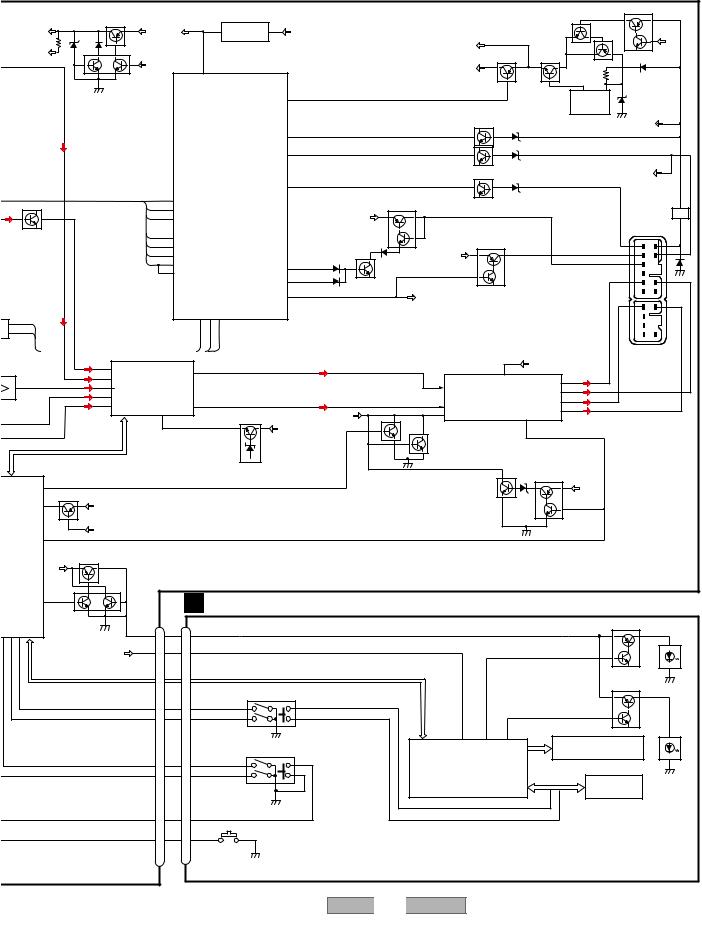
|
|
|
|
5 |
|
|
|
|
|
|
|
|
6 |
|
|
|
|
|
7 |
|
|
|
|
8 |
|
|
|
|
|
|
|
|
|
|
|
|
|
|
|
|
|
|
|
|
|
|
|
|
|
|
A |
|
|
|
|
|
|
|
|
|
|
|
|
|
|
|
|
|
|
|
|
|
|
|
Q426 |
|
|
|
|
|
|
Q441 |
|
|
|
|
|
|
RESET |
|
|
|
|
|
|
|
|
|
|
Q425 |
|
|
BU |
|
|
|
|
|
|
|
|
|
1 |
|
2 |
|
|
|
|
|
|
|
|
|
|
|
|
|
|
|
AUDIO+B |
|
|
BU |
|
RESET |
|
IC 782 |
VDD |
|
|
|
|
|
|
|
|
|
|
|
|
||||
|
|
|
|
|
|
|
|
|
|
|
|
|
|
|
|
Q424 |
|
|
|||||||
|
|
|
|
|
|
|
|
|
|
|
|
|
|
|
|
|
|
|
|
|
|
|
|
VDD |
|
|
|
|
|
|
|
|
|
|
|
S-80835CNNB-B8U |
|
|
|
|
|
VDD |
|
|
|
|
|
|
|||
|
1/2VCC |
Q442 |
|
|
|
|
|
|
|
|
|
|
|
|
|
|
|
|
|
||||||
|
|
|
|
|
|
|
|
|
|
|
|
|
|
|
|
|
|
|
|
|
|
||||
|
|
|
|
|
SYSPW |
|
|
|
|
|
|
|
|
|
|
|
|
Q422 |
Q421 |
|
|
|
|
||
|
|
|
|
|
|
|
12 |
|
|
|
|
|
|
|
SWVDD |
|
|
|
|
|
|
|
|||
|
|
|
|
|
|
|
|
|
|
|
|
|
|
|
|
|
|
|
|
|
|
|
|
||
|
|
|
|
|
|
|
|
|
|
|
|
|
|
|
|
|
|
|
|
|
|
|
|
|
|
|
|
|
|
|
|
|
|
|
reset |
|
|
|
|
|
|
|
|
|
|
|
3 |
2 |
|
|
|
|
|
|
|
|
|
|
|
|
|
|
65 |
|
|
|
|
|
|
|
|
|
|
|
|
||
|
|
|
|
|
|
|
|
|
|
|
|
swvdd |
|
|
|
|
|
|
|
|
IC 421 |
|
|
|
|
|
|
|
|
|
|
|
|
|
|
|
|
|
|
|
|
|
|
|
|
|
|
|
|
||
|
|
|
|
|
|
|
|
|
|
|
|
|
|
|
|
|
|
|
Q404 |
B SENSE |
S-812C56AUA-C3K |
BU |
|
||
|
|
|
|
|
|
|
|
|
|
|
|
|
|
|
|
|
|
|
BU |
|
|
|
|||
|
|
|
|
|
|
|
|
|
|
|
|
bsen |
73 |
|
|
|
|
|
|
|
|
|
|
|
|
|
|
|
|
|
|
|
|
|
|
|
|
|
|
|
|
|
|
|
|
|
|
|
|
|
|
|
|
|
|
|
|
|
|
|
|
|
|
asen |
20 |
|
|
|
|
|
|
|
ACC |
|
|
|
B |
|
|
|
|
|
|
|
|
|
|
|
|
|
|
|
|
|
|
|
|
|
|
|
|
|
|
|
|
|
|
|
|
|
|
|
SYSTEM CONTROL |
|
|
|
|
|
|
|
Q402 |
A SENSE |
|
|
|
ACC |
|
||
|
|
|
|
|
|
|
|
|
|
|
|
|
|
|
|
|
|
|
|
|
|
||||
|
|
|
|
|
|
|
|
|
|
IC 701(1/2) |
isen |
58 |
|
|
|
|
|
|
|
ILL |
|
|
|
|
|
|
|
|
|
|
|
|
|
|
|
|
|
|
|
|
|
|
|
|
|
|
|
|
|||
R |
|
|
|
|
|
|
27 |
|
|
PD5949B |
|
|
|
|
ANT +B |
|
|
Q403 |
I SENSE |
|
|
|
|
|
|
|
|
|
|
|
|
locl |
|
|
|
|
|
|
|
|
|
|
|
|
|
|
|||||
M |
|
|
|
|
|
|
25 |
SD |
|
|
|
|
|
|
|
Q454 |
|
|
|
|
|
|
|
|
LPF |
|
|
|
|
|
|
97 |
SL |
|
|
|
|
|
|
BU |
|
|
|
|
|
|
|
|
|
||
|
|
|
|
|
|
|
|
|
|
|
|
|
|
|
|
|
|
|
|
|
|
||||
|
Q561 |
|
|
|
PCE1 23 |
|
|
|
|
|
|
|
|
|
|
WF AMP+B |
|
|
CN471 |
|
|||||
|
|
|
|
PCE1 |
|
|
|
|
|
|
|
|
|
|
|
|
|
|
|||||||
|
|
|
|
|
pck |
2 |
|
|
|
|
|
|
|
|
|
|
|
ILL |
|
+B |
|||||
|
|
|
|
|
pck |
|
|
|
|
|
|
|
Q455 |
|
|
Q451 |
|
|
|
|
|||||
|
|
|
|
|
ce@ |
22 |
|
|
|
|
|
|
|
|
|
|
|
|
|
AMP |
|
ACC |
|||
|
|
|
|
|
PCE2 |
|
|
|
|
|
|
|
|
BU |
|
|
|
|
|
||||||
|
|
|
|
|
PDIO |
1 |
|
|
|
|
|
|
|
|
|
|
|
|
|
ANT |
|
|
|||
|
|
|
|
|
PDO |
|
|
|
FMPW |
44 |
|
|
|
|
|
|
|
|
|
|
|
||||
|
|
|
|
|
|
100 |
PDI |
|
|
|
45 |
|
|
|
|
|
|
|
|
|
FL- |
|
FL+ |
||
|
|
|
|
|
|
|
|
|
|
|
|
AMPW |
|
Q453 |
|
|
|
|
|
|
|
|
|||
|
|
|
|
|
|
|
|
|
|
|
|
|
|
|
|
|
|
|
|
|
|
|
|
||
|
|
|
|
|
|
|
|
|
|
|
|
|
49 |
|
|
|
|
|
Q452 |
|
|
|
|
|
|
|
|
|
|
|
|
|
|
|
|
|
|
SYSPW |
|
|
SYSPW |
|
|
|
|
|
|
|
|
||
|
|
|
|
|
|
|
|
|
|
|
|
|
|
|
|
|
|
|
|
RL- |
|
|
|||
|
|
|
|
|
|
|
|
|
|
RX1 IPPW |
|
|
|
|
|
|
|
|
|
|
|
|
|
RL+ |
|
RIVER |
|
|
|
|
|
|
|
TX |
|
|
|
|
|
|
|
|
|
|
|
|
|
|
C |
||
1 |
TX |
|
|
|
|
|
|
|
30 |
29 47 |
|
|
|
|
|
|
|
|
|
|
|
|
|
|
|
FP 2 |
RX |
|
|
|
DSP/ |
|
|
|
TX |
RX |
|
|
|
|
|
|
|
|
|
|
|
|
|
|
|
|
|
|
ELECTRONIC VOLUME/ |
|
|
|
|
|
|
|
|
|
|
|
|
|
|
|
|||||||
IPPW |
|
|
SOURCE SELECTOR |
|
|
|
|
|
|
|
|
|
|
|
|
|
|
|
|
|
|||||
1 |
|
AM |
|
|
|
|
|
|
|
|
|
|
|
|
|
|
|
|
BU |
|
|
|
|
|
|
4M |
|
|
84 |
LIN-4 |
|
|
|
|
5 |
|
|
|
|
|
|
|
|
|
|
6,20 |
|
|
|
|
|
|
FM L |
|
|
|
|
FL |
|
|
|
|
|
|
|
|
|
|
|
|
|
|
|
||||
|
81 |
LIN-1 |
|
|
|
|
|
|
|
|
|
|
|
|
|
|
|
|
|
|
|||||
|
|
IC 351 |
|
|
|
|
|
|
|
|
|
|
|
|
|
VCC |
|
3 |
|
|
|
||||
7 7 |
LANL |
83 |
|
|
|
|
|
|
|
|
|
|
12 |
|
|
FL- |
|
|
|
||||||
LIN-3 |
|
|
|
|
|
|
|
|
|
|
FLIN |
POWER AMP |
|
|
|
|
|||||||||
|
|
CD L |
82 |
PM2010A |
|
|
|
|
|
|
|
|
|
|
FL+ |
5 |
|
|
|
||||||
|
|
LIN-2 |
|
|
|
|
|
|
|
|
|
|
|
|
|
|
|||||||||
|
|
CS L |
85 |
|
|
|
|
14 |
|
|
|
|
|
|
|
15 |
|
IC 801 |
RL- |
19 |
|
|
|
||
|
|
LIN-5 |
|
|
|
RL |
|
|
|
|
|
|
MUTE |
RLIN |
TDA7386 |
RL+ 17 |
|
|
|
||||||
|
|
|
|
|
VDD |
|
DSP VDD (3.3V)REGULATOR |
AUDIO+B |
|
22 |
|
|
|
||||||||||||
|
|
|
|
|
|
|
|
|
|
Q801 |
|
|
MUTE |
|
STBY |
|
|
|
|
|
|||||
|
|
|
|
|
|
|
3,8,18,27,37,49,76,77,96 |
Q351 |
|
|
|
|
|
|
|
4 |
|
|
|
|
|
||||
|
|
|
|
|
|
|
|
|
|
|
|
|
|
|
|
|
|
|
|
||||||
|
|
|
|
|
|
|
|
|
|
|
|
AUDIO+B |
|
|
|
|
|
|
|
|
|
|
|
||
|
|
|
|
|
|
|
|
|
|
|
|
|
|
Q802 |
|
|
|
|
|
SYSPW |
|
|
|
||
|
|
|
|
|
|
|
|
|
|
|
|
|
|
|
|
|
|
|
|
|
|
|
|
|
|
|
dsprst,dsperr,IFOK,dspack,IFDI,IFDO,IFCLK,dspcs |
|
|
|
|
|
|
|
|
|
|
|
|
|
|
BU MUTE |
|
|
|
|
|||||
|
|
|
|
|
|
|
|
|
|
|
|
|
|
|
|
|
|
|
|
|
|
|
|
||
|
|
|
|
|
|
|
|
|
|
|
|
|
|
|
|
|
|
|
|
Q803 |
Q805 |
|
|
|
|
|
|
|
|
|
|
|
|
|
|
|
|
|
|
|
|
|
|
|
|
|
|
|
|
|
|
|
SYSMUTE |
42 |
|
|
|
|
|
|
|
|
|
|
|
|
|
|
|
|
|
|
|
BU |
|
|
D |
|
|
Q701 |
|
|
|
|
|
|
|
|
|
|
|
|
|
|
|
|
|
|
|
|
|
|
|
LANMUTE |
46 |
SWVDD |
|
|
|
|
|
|
|
|
|
|
|
|
|
|
|
|
|
SYSPW |
|
|
|
||
|
|
|
|
|
|
|
|
|
|
|
|
|
|
|
|
|
|
|
|
|
Q804 |
|
|
|
|
|
|
49 |
LANMUT |
|
|
|
|
|
|
|
|
|
|
|
|
|
|
|
|
|
|
|
|
|
|
|
SYSPW |
|
|
|
|
|
|
|
|
|
|
|
|
|
|
|
|
|
|
|
|
|
|
|
|
|
|
|
|
|
|
|
|
|
|
|
|
|
|
|
|
|
|
|
|
|
|
|
|
|
|
/2) |
|
|
|
|
|
|
|
|
|
|
|
|
|
|
|
|
|
|
|
|
|
|
|
|
|
B |
|
|
Q851 |
|
|
|
|
|
|
|
|
|
|
|
|
|
|
|
|
|
|
|
|
|
|
|
|
|
|
|
|
|
|
|
|
|
|
|
|
|
|
|
|
|
|
|
|
|
|
|
|
NTROL |
BU |
|
|
|
|
|
|
|
|
|
|
|
|
|
|
|
|
|
|
|
|
|
|
|
|
|
|
|
Q852 |
|
|
|
|
B KEYBOARD UNIT |
|
|
|
|
|
|
|
|
|
|
|
||||||
|
ILLPWM |
28 |
|
|
|
|
|
|
|
|
|
|
|
|
|
|
|
|
|||||||
|
|
|
|
|
|
|
|
|
|
|
|
|
|
|
|
|
|
||||||||
ENC2P ENC1M |
|
|
|
|
|
|
|
|
|
|
|
|
|
|
|
|
|
|
|||||||
ENC1P |
|
|
|
CN479 |
|
|
|
CN901 |
|
|
|
|
|
|
|
|
|
|
|
|
Q972 |
|
|
||
|
|
|
|
|
|
|
|
|
|
|
|
|
|
|
|
|
|
ILLUMINATION |
|
|
|||||
|
|
|
SWILL+B |
1 |
|
1 |
SWILLB |
|
|
|
|
|
|
|
|
|
|
|
|
||||||
7 86 85 |
|
|
|
|
|
|
|
|
|
|
|
|
|
|
|
|
|
|
|
|
|
|
|||
|
|
|
|
|
|
|
|
|
|
|
|
|
|
|
|
|
|
|
|
|
|
|
|
||
|
|
|
SWVDD |
SWVDD |
3 |
|
3 |
SWVD |
|
|
|
|
|
|
|
|
ILL |
|
|
|
|
|
|
||
|
|
|
|
|
|
|
|
|
|
|
|
|
|
|
|
|
|
|
|
|
|||||
|
|
|
|
|
|
|
|
|
|
|
|
|
|
|
|
|
|
|
|
|
|
|
Q971 |
|
E |
|
|
LCE,LCK,LDO,LDI |
|
|
|
|
|
|
|
|
LCE,LCK,LDO,LDI |
|
|
|
|
|
|
|
|
|
|
||||
|
|
|
|
|
|
|
|
|
|
|
|
|
|
|
|
|
|
|
|
|
|||||
|
|
|
|
|
|
|
|
|
|
|
TUNE•FILE(FH-M8047ZT/XN/ES,FH-M8047ZT/XIN/ES) |
|
|
|
|
|
|
|
Q982 |
|
|
||||
|
|
|
|
|
|
|
|
|
|
|
PWR•VOL(FH-M8147ZT/XN/ES,FH-M8147ZT/XIN/ES) |
|
|
|
|
|
|
|
|
|
|
||||
|
|
|
|
|
|
|
|
|
|
|
|
S932 |
|
|
|
|
|
|
|
|
|
|
|
|
|
|
|
|
|
|
ENC1P |
10 |
|
10 |
|
|
ENC1P |
|
KD4 |
|
|
|
|
|
|
|
|
|
|
|
|
|
|
|
|
|
|
|
|
|
|
|
|
|
|
|
|
|
|
BL |
|
|
|
|
|
||
|
|
|
|
|
ENC1M 11 |
|
11 |
|
|
ENC1M |
|
KST4 |
|
|
|
|
|
|
|
|
|
|
|
||
|
|
|
|
|
|
|
|
|
|
|
|
|
|
|
|
|
|
85 |
74 |
75 |
|
|
Q981 |
|
|
|
|
|
|
|
|
|
|
|
|
|
|
|
|
|
|
|
|
|
|
|
|
|
|||
|
|
|
|
|
|
|
|
|
|
|
PWR•VOL(FH-M8047ZT/XN/ES,FH-M8047ZT/XIN/ES) |
|
|
VDD |
KS1/P1 |
KS2/P2 |
|
|
|
|
|
||||
|
|
|
|
|
|
|
|
|
|
|
TUNE•FILE(FH-M8147ZT/XN/ES,FH-M8147ZT/XIN/ES) |
|
|
|
LCD |
|
|
||||||||
|
|
|
|
|
|
|
|
|
|
|
|
S931 |
|
|
|
|
|
|
|
|
|
|
|||
|
|
|
|
|
ENC2P 12 |
|
12 |
|
|
ENC2P |
|
|
|
|
|
|
LCD DRIVER/ |
|
|
|
|
|
|
||
|
|
|
|
|
ENC2M 13 |
|
13 |
|
|
ENC2M |
|
|
|
|
|
KEY CONTROLLER |
|
|
|
|
LCD |
||||
|
|
|
|
|
|
|
|
|
|
|
|
|
|
|
|
|
|
IC 901 |
|
|
KEY MATRIX |
BACKLIGHT |
|||
|
|
|
|
|
|
|
|
|
|
|
|
|
|
|
|
|
|
LC75816WS-8722 |
KEY DATA |
|
|||||
|
|
|
|
|
|
|
|
|
|
|
|
|
|
|
|
|
|
|
|
|
|||||
|
|
|
|
|
|
|
|
|
|
|
|
|
|
|
|
|
|
|
|
|
KD4 |
|
|
|
|
|
|
|
|
|
POWER |
4 |
|
4 |
POWER |
|
|
|
|
|
|
|
|
|
|
KST4 |
|
|
|
|
|
|
|
|
|
|
|
|
|
|
|
EJECT |
|
|
|
|
|
|
|
|
|
|
|
|
|
F |
|
|
|
|
|
|
cdej |
17 |
|
17 |
cdej |
|
|
|
|
|
|
|
|
|
|
|
|
|
|
||
|
|
|
|
|
|
|
|
|
|
S933 |
|
|
|
|
|
|
|
|
|
|
|
|
|
|
|
|
|
|
|
5 |
|
|
|
|
|
|
|
6 |
FH-M8047ZT/XN/ES |
7 |
|
|
|
|
8 |
15 |
|||||
|
|
|
|
|
|
|
|
|
|
|
|
|
|
|
|
|
|
|
|
||||||
|
|
|
|
|
|
|
|
|
|
|
|
|
|
|
|
|
|
|
|
|
|||||
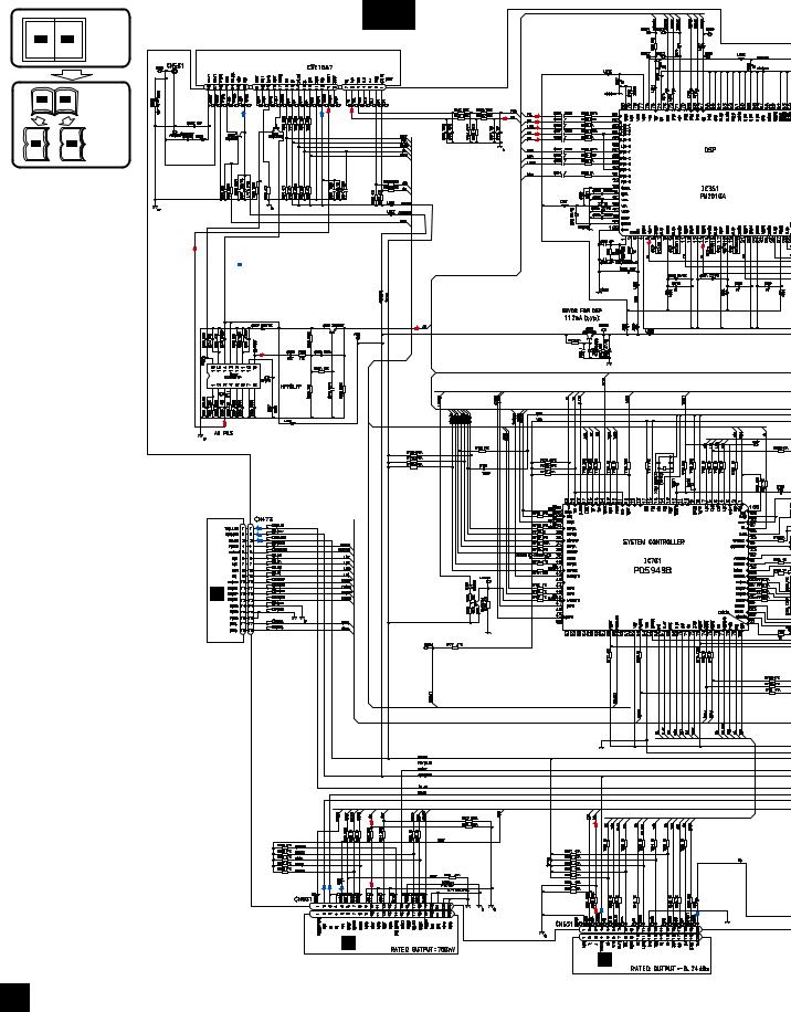
1 |
2 |
3 |
4 |
3.2 OVERALL CONNECTION DIAGRAM(GUIDE PAGE)
Note: When ordering service parts, be sure to refer to " EXPLODED VIEWS AND PARTS LIST" or
"ELECTRICAL PARTS LIST".
A
A-a
|
|
Large size |
|
|
A-a |
A-b |
SCH diagram |
|
|
|
|
|
||
|
|
|
FM/AM TUNER UNIT |
|
|
|
|
|
TAPE:-11dBs |
A-a |
A-b |
Guide page |
|
FM:-27dBs |
|
AM:-28dBs |
|||
|
|
|
FM:-24dBs |
CD: 0dBs |
|
|
|
|
|
|
|
P |
P |
|
A-a |
A-b |
Detailed page |
|
|
B
 : SIGNAL LINE
 P : POWER SUPPLY LINE
AM:-12dBs
C
D
E
P
P
P
B CN901
CD:0dBs
TAPE:-11dBs
P |
P |
P |
P
P
C CN901
F
D CN251
A
16 |
|
FH-M8047ZT/XN/ES |
|
|
1 |
2 |
|
3 |
4 |
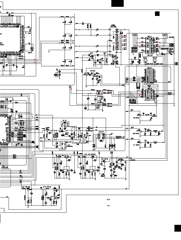
5 |
6 |
7 |
8 |
A
A-b
A MAIN UNIT
SPOUT BAL
TAPE:+21dBs
FM:+14dBs
AM:+17dBs
CD:+27dBs
B
P
P
P
C
 >
>
P
D
E
NOTE :
Symbol indicates a resistor.
No differentiation is made between chip resistors and discrete resistors.
Symbol indicates a capacitor.
No differentiation is made between chip capacitors and discrete capacitors.
The > mark found on some component parts indicates the importance of the safety factor of the part. Therefore, when replacing, be sure to use parts of identical designation.
Decimal points for resistor and capacitor fixed values are expressed as :
2.2 |
← |
2R2 |
0.022 |
←R022 |
|
F
A
|
|
|
|
|
|
|
|
|
|
FH- |
M8047ZT/XN/ES |
|
|
17 |
|
5 |
6 |
|
|
|
7 |
8 |
|
|
|
||||||
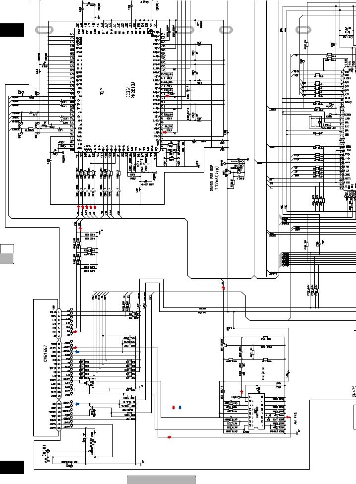
1
A
A-b 1
B
C
A-a A-b
D
E UNITTUNER
FM/AM
F
A-a
18
1
CD: 0dBs
AM:-28dBs
FM:-27dBs
TAPE:-11dBs
FM:-24dBs
P
P
2 |
3 |
4 |
2 |
3 |
4 |
LINE |
SUPPLY LINE |
AM:-12dBs |
: SIGNAL |
: POWER |
|
|
P |
|
FH-M8047ZT/XN/ES
2 |
|
3 |
4 |
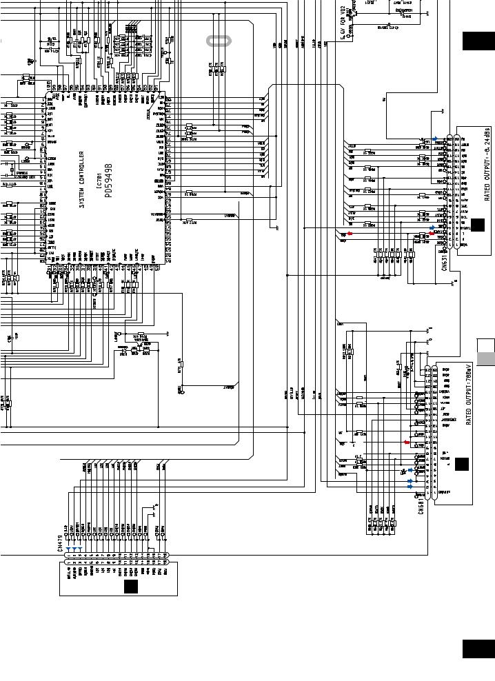
5 |
6 |
7 |
8 |
A
5 |
A-b |
|
TAPE:-11dBs
P
B
D CN251
P
C
A-a A-b
D
CD:0dBs
P
P
P
 C CN901
E
P |
P |
P |
BCN901
F
A-a
|
|
|
|
|
|
|
|
|
|
FH- |
M8047ZT/XN/ES |
|
|
19 |
|
5 |
6 |
|
|
|
7 |
8 |
|
|
|
||||||
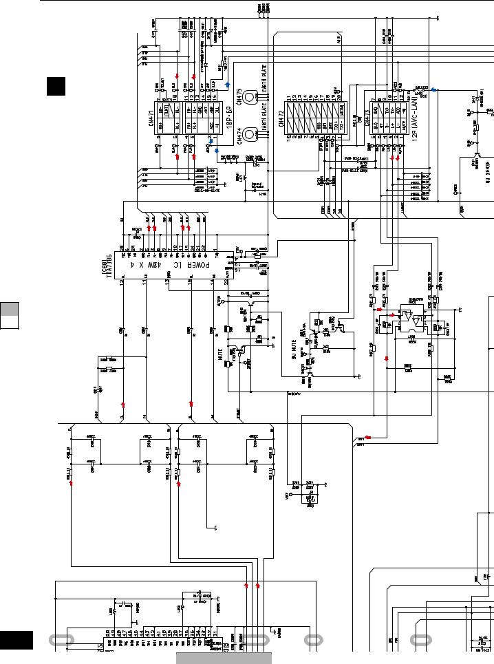
1 |
2 |
3 |
4 |
A |
|
|
|
|
MAIN UNIT |
|
|
|
|
A |
|
|
P |
> |
B |
SPOUT BAL |
TAPE:+21dBs FM:+14dBs AM:+17dBs CD:+27dBs |
P |
|
|
|
|
P |
|
C
A-a A-b
D
E
F
A-b |
1 |
2 |
3 |
4 |
|
|
|||||
20 |
|
FH-M8047ZT/XN/ES |
|
|
|
1 |
2 |
3 |
4 |
||
|
P
5
5 6
M8047ZT/XN/ES-FH
7
8 |
|
|
|
21 |
b-A |
|
NOTE :
Symbol indicates a resistor.
No differentiation is made between chip resistors and discrete resistors.
Symbol indicates a capacitor.
No differentiation is made between chip capacitors and discrete capacitors.
The > mark found on some component parts indicates the importance of the safety factor of the part. Therefore, when replacing, be sure to use parts of identical designation.
A-a A-b
F |
E |
D |
C |
B |
P
5
6
7
Decimal points for resistor and capacitor fixed values are expressed as :
2.2 |
← |
2R2 |
|
|
|||
0.022 |
← |
R022 |
|
|
|||
8
A
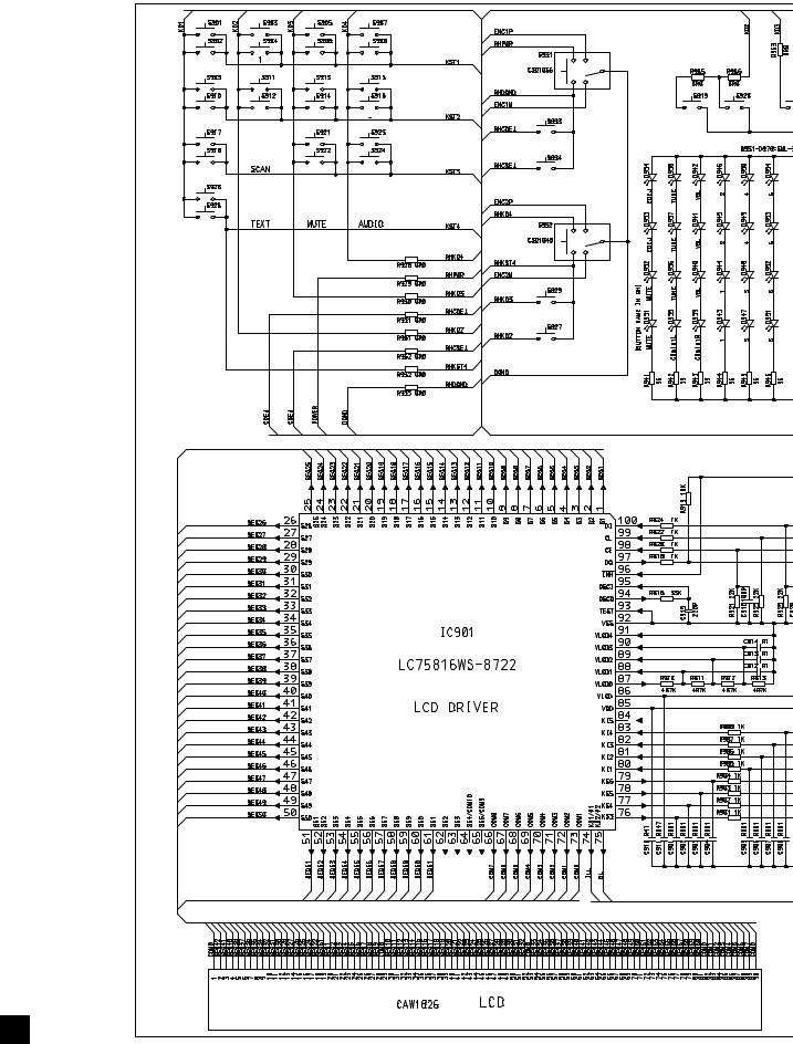
1 |
2 |
3 |
4 |
3.3 KEYBOARD UNIT(FH-M8047ZT/XN/ES,FH-M8047ZT/XIN/ES)
A
DISC |
1 |
4 |
6 |
|
|
|
|
|
|
PWR•VOL |
|
TAPE |
2 |
3 |
5 |
SCAN SCAN |
DOW |
|
|
|
|
CD EJECT |
|
FM |
|
DOWN |
UP |
TAPE EJECT |
|
|
|
|
|
|
B |
AM |
TUNE•FILE
MUTE
TEXT
C
D
E
F
B
22 |
|
FH-M8047ZT/XN/ES |
|
|
1 |
2 |
|
3 |
4 |
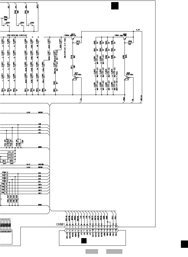
5 |
6 |
7 |
8 |
B KEYBOARD UNIT
A
SCAN |
DOWN |
UP |
||
|
|
|
|
|
|
|
|
|
|
A CN479
FH-M8047ZT/XN/ES
5 |
6 |
|
|
|
7 |
B
C
D
E
F
B
23
8

1 |
2 |
3 |
4 |
3.4 KEYBOARD UNIT(FH-M8147ZT/XN/ES,FH-M8147ZT/XIN/ES)
A
AM |
1 |
4 |
6 |
TUNE•FILE |
|
|
|
|
|
|
|
|
|
FM |
2 |
3 |
5 |
DOWN |
UP |
SC |
|
|
|
|
MUTE |
|
|
TAPE |
|
DOWN |
UP |
TEXT |
|
|
|
|
|
|
|
|
B |
DISC |
PWR•VOL
CD EJECT
TAPE EJECT
C
D
E
F
B
24 |
|
FH-M8047ZT/XN/ES |
|
|
1 |
2 |
|
3 |
4 |
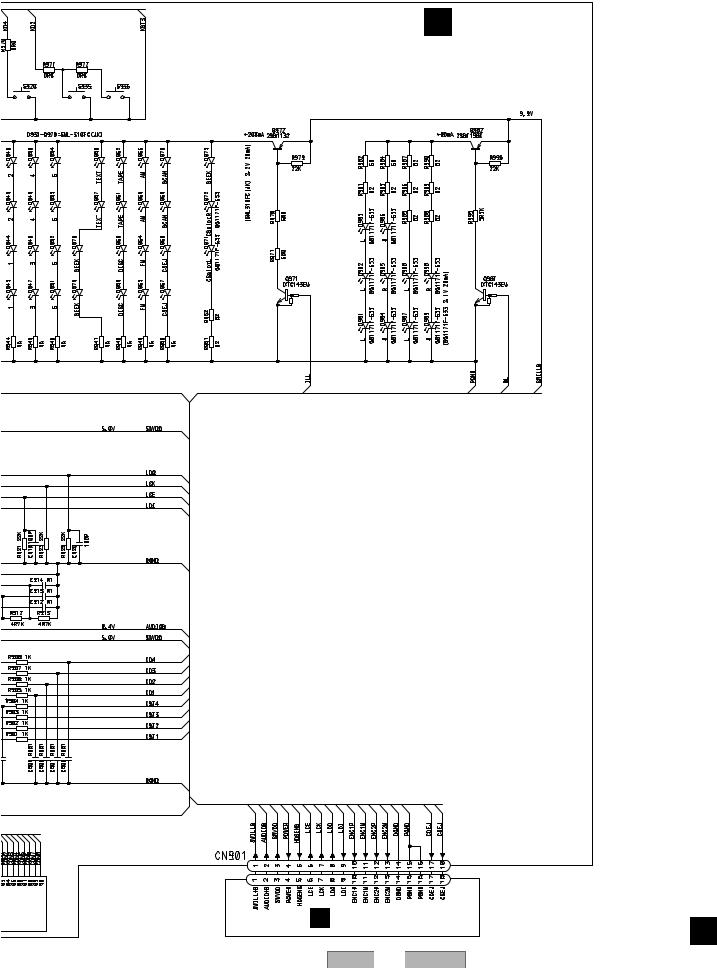
5 |
6 |
7 |
8 |
B KEYBOARD UNIT
A
UP |
SCAN |
|
SCAN |
|
|
|
|
A CN479
FH-M8047ZT/XN/ES
5 |
6 |
|
|
|
7 |
B
C
D
E
F
B
25
8
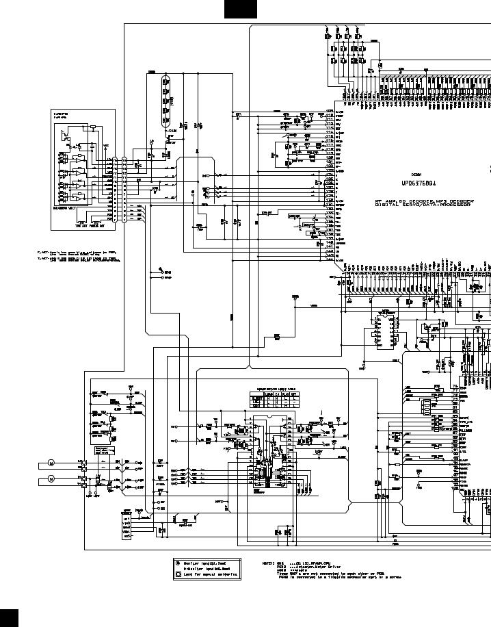
1 |
2 |
3 |
4 |
3.5 CD MECHANISM MODULE(GUIDE PAGE)
A
C-a
PICKUP UNIT (P10)(SERVICE)
S |
C |
T |
F |
S |
C |
T |
F |
B |
|
|
|
|
# |
|
CN101 |
|
F |
F |
|
T |
F |
F |
T |
|
|
T |
T |
|
|
F |
F |
|
T |
T |
F |
T |
T |
F |
|
|
|
T |
|
|
T |
0 |
|
F |
|
|
F |
|
|
|
! |
C |
|
|
|
SWITCHES: |
|
|
CD CORE UNIT(S10MP3) |
|
|
S901 |
: HOME SWITCH.....ON-OFF |
|
S902 |
: CLAMP SWITCH....ON-OFF |
D |
S903 |
: DSCSNS SWITCH....ON-OFF |
S904 : 12EJ SWITCH....ON-OFF |
||
|
S905 |
: 8EJ SWITCH....ON-OFF |
The underlined indicates the original switch position.
5/3.3 |
1 |
@ |
|
|
|
T |
5 |
|
7 |
|
|
|
|
|
|
|
|
F |
6 |
SPINDLE MOTOR |
|
|
|
M1 CXB6007 |
8 |
|
2 |
S
C
 3
3
E
S |
|
|
|
R735 |
|
|
|
|
|
S |
F |
|
|
47K |
|
|
|
|
|
|
F |
|
|
|
C |
T |
|
|
|
T |
|
|
|
|
C |
|
|
|
|
S |
S |
C |
C |
LOADING/CARRIAGE |
|
|
MOTOR |
CD DRIVER |
|
M2 CXB8933 |
||
|
SW 3.3 REGULATOR
F
C
26 |
|
FH-M8047ZT/XN/ES |
|
|
1 |
2 |
|
3 |
4 |
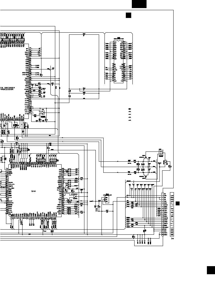
5 |
6 |
 9
9
 $
$

 ^
^
 %
%
PE5427A
MICRO COMPUTER
5 |
6 |
7 |
8 |
A
C-b
C CD CORE UNIT(S10MP3)
D-RAM
B
C
SIGNAL LINE
F |
FOCUS SERVO LINE |
|
T |
||
TRACKING SERVO LINE |
||
C |
||
CARRIAGE SERVO LINE |
||
S |
||
SPINDLE SERVO LINE |
||
|
D
 *
*
 &
&
4
CN901
3.3 REGULATOR
A
CN601 E
F
C
|
|
|
|
|
|
FH- |
M8047ZT/XN/ES |
|
|
27 |
|
|
|
|
7 |
8 |
|
|
|
||||
Loading...