

Pioneer AVIC-N2, AVIC-X1R Service Manual
PIONEER CORPORATION 4-1, Meguro 1-chome, Meguro-ku, Tokyo 153-8654, Japan
PIONEER ELECTRONICS (USA) INC. P.O. Box 1760, Long Beach, CA 90801-1760, U.S.A.
PIONEER EUROPE NV Haven 1087, Keetberglaan 1, 9120 Melsele, Belgium
PIONEER ELECTRONICS ASIACENTRE PTE. LTD. 253 Alexandra Road, #04-01, Singapore 159936
PIONEER CORPORATION 2005
NOTE:
Manufactured under license from Dolby Laboratories. "Dolby" and the double-D symbol are trademarks
of Dolby Laboratories.
This product has the unit part number as below.
Unit Part No.
CPN1955
CPN1953
CPN1954
CPN1952
Description
Navigation Unit(AVIC-N2/XU/UC)
Hideaway Unit(AVIC-N2/XU/UC)
Navigation Unit(AVIC-X1R/XU/EW)
Hideaway Unit(AVIC-X1R/XU/EW)
*) The unit part numbers listed above are not for the service components.
ORDER NO.
CRT3423
AVIC-N2/XU/UC
DVD MULTIMEDIA AV NAVIGATION SERVER
AVIC-N2
/XU/UC
DVD AV NAVIGATION HEAD-UNIT
AVIC-X1R
This service manual should be used together with the following manual(s):
Model No. Order No. Mech.Module Remarks
CX-3016 CRT3056 MS3 DVD Mech. Module:Circuit Description, Mech. Description, Disassembly
/XU/EW
For details, refer to "Important Check Points for Good Servicing".
K-ZZW. FEB. 2005 Printed in Japan
O
e
r
ect
the
d
the
y
y
y
y
g
to
ARNING
eadlde
d
ta
ectrica
to
the
5
.
g
.
:
.
r
m
e.
g
g.
1234
SAFETY INFORMATION
A
AUTI
This service manual is intended for qualified service technicians; it is not meant for the casual do-it-yourself
Qualified technicians have the necessary test equipment and tools, and have been trained to properly and safely repai
Improperlyerformed repairs
ou
renotualifiedtoerform therepair
ARNING
B
Thisroduct
Health & Safety Code Section 25249.6 - Proposition 6
This product contains mercury. Disposal of this material may be regulated due to environmental considerations.
For disposal or recyclin
Alliance: www.eiae.or
C
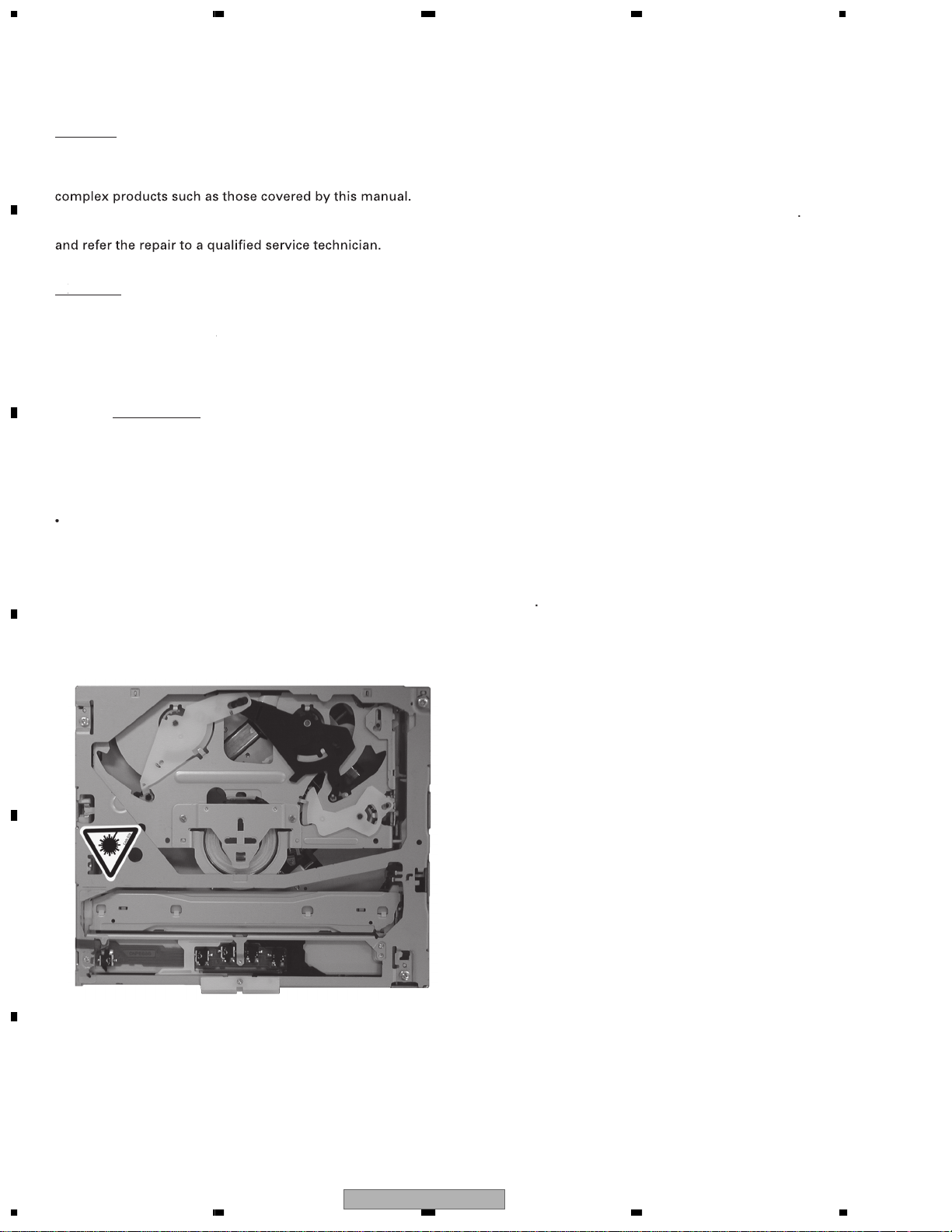
Safety Precautions for those who Service this Unit
Follow the adjustment steps in the service manual when servicing this unit. When checkin
or adjusting the emitting power of the laser diode exercise caution in order to get safe, reliable results
ion
During repair or tests, minimum distance of 13cm from the focus lens must be kept
During repair or tests, do not view laser beam for 10 seconds or longe
The triangular label is attached to the mechanis
nit fram
ntainsl
information, please contact your local authorities or the Electronics Industries
n adversely
r
n
ff
thisroduct
in
l
safetyndreliability theroduct
roperlyndsafel
l
arts
ntain
hemicalswhich rknown
ou
ndmayvoi
houldnotrisktryin
warrant
D
E
F
2
1234
AVIC-N2/XU/UC
5678
A
CLASS 1
LASER PRODUCT
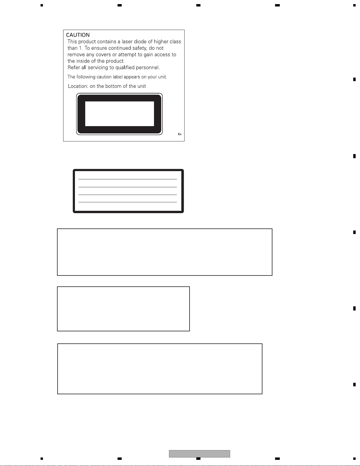
On the top of the player.
CAUTION :
VORSICHT :
ADVARSEL :
VARNING :
VARO! :
The AEL (accessible emission level )of the laser power output is less than CLASS 1
but the laser component is capable of emitting radiation exceeding the limit for
CLASS 1.
A specially instructed person should do servicing operation of the apparatus.
VISIBLE AND INVISIBLE LASER RADIATION WHEN OPEN.
AVOID EXPOSURE TO BEAM.
SICHTBARE UND UNSICHTBARE LASERSTRAHLUNG, WENN
ABDECKUNG GEÖFFNET NICHT DEM STRAHL AUSSETZEN!
SYNLIG OG USYNLIG LASERSTRÅLING VED ÅBNING
UNDGÅ UDSÆTTELSE FOR STRÀLING.
SYNLIG OCH OSYNLIG LASERSTRÅLNING NÄR DENNA
DEL ÄR ÖPPNAD BETRAKTA EJ STRÅLEN.
AVATTAESSA ALTISTUT NÄKYVÄ JA NÄKYMÄTTÖMÄLLE
LASERSATEIL YLLE. ÄLÄ KATSO SÄTEESEN.
VRW1860
WARNING!
B
C
D
Laser diode characteristics
Wave length:
DVD:640~660nm
CD:770~810nm
Maximum output:2.48mw(Emitting period :9sec.)
DVD:705µw(Emitting period : unlimited)
Additionla Laser Caution
Transistors Q1101 and Q1102 in PCB drive the laser diodes for DVD and CD
respectively. When Q1101 or Q1102 is shorted between their terminals,
the laser diodes for DVD or CD will radiate beam. If the top cover is removed
with no disc loaded while such short-circuit is continued, the naked eyes may
be exposed to the laser beam.
56
AVIC-N2/XU/UC
7
E
F
3
8

1234
- Service Precautions
A
1. You should conform to the regulations governing the product (safety, radio and noise, and other regulations),
and should keep the safety during servicing by following the safety instructions described in this manual.
DVD MECHANISM MODULE section precaution
1. Before disassembling the unit, be sure to turn off the power. Unplugging and plugging the connectors during
power-on mode may damage the ICs inside the unit.
2. To protect the pickup unit from electrostatic discharge during servicing, take an appropriate treatment
(shorting-solder) by referring to "the DISASSEMBLY".
3. After replacing the pickup unit, be sure to check the grating.
4. During disassembly, be sure to turn the power off since an internal IC might be destroyed when a connector is
plugged or unplugged.
B
NAVIGATION UNIT section precaution
1. Inverter for LCD back light becomes a high voltage.
2. When inspecting the touch panel, use something thin with a round tip such as the touch pen. Furthermore,
do not apply excessive force to the touch panel.
3. Since this product does not have OSD IC, OSD for adjustment is displayed by using GGF1416 and GGF1463
at the time of monitor adjustment. As you will find lands for 14 pins with 0.8mm pitch at the left top part of
the monitor board, directly solder a flexible PCB of GGD1323 for adjustment. As GGD1322 is not used, be
careful not to short the terminal.
4. The region code determination at the time of DVD hardware change is made by the destination (UC: Region 1,
EW: Region 2) of the car control unit.
5. If you reconnected the Hide-away unit, press the RESET button.
C
D
is a trademark of DVD Format/Logo Licensing Corporation.
E
F
4
1234
AVIC-N2/XU/UC
5678
[Important Check Points for Good Servicing]
In this manual, procedures that must be performed during repairs are marked with the below symbol.
Please be sure to confirm and follow these procedures.
1. Product safety
Please conform to product regulations (such as safety and radiation regulations), and maintain a safe servicing environment by
following the safety instructions described in this manual.
1 Use specified parts for repair.
Use genuine parts. Be sure to use important parts for safety.
2 Do not perform modifications without proper instructions.
Please follow the specified safety methods when modification(addition/change of parts) is required due to interferences such as
radio/TV interference and foreign noise.
3 Make sure the soldering of repaired locations is properly performed.
When you solder while repairing, please be sure that there are no cold solder and other debris.
Soldering should be finished with the proper quantity. (Refer to the example)
4 Make sure the screws are tightly fastened.
Please be sure that all screws are fastened, and that there are no loose screws.
5 Make sure each connectors are correctly inserted.
Please be sure that all connectors are inserted, and that there are no imperfect insertion.
6 Make sure the wiring cables are set to their original state.
Please replace the wiring and cables to the original state after repairs.
In addition, be sure that there are no pinched wires, etc.
7 Make sure screws and soldering scraps do not remain inside the product.
Please check that neither solder debris nor screws remain inside the product.
8 There should be no semi-broken wires, scratches, melting, etc. on the coating of the power cord.
Damaged power cords may lead to fire accidents, so please be sure that there are no damages.
If you find a damaged power cord, please exchange it with a suitable one.
9 There should be no spark traces or similar marks on the power plug.
When spark traces or similar marks are found on the power supply plug, please check the connection and advise on secure
connections and suitable usage. Please exchange the power cord if necessary.
0 Safe environment should be secured during servicing.
When you perform repairs, please pay attention to static electricity, furniture, household articles, etc. in order to prevent injuries.
Please pay attention to your surroundings and repair safely.
A
B
C
D
2. Adjustments
To keep the original performance of the products, optimum adjustments and confirmation of characteristics within specification.
Adjustments should be performed in accordance with the procedures/instructions described in this manual.
3. Lubricants, Glues, and Replacement parts
Use grease and adhesives that are equal to the specified substance.
Make sure the proper amount is applied.
4. Cleaning
For parts that require cleaning, such as optical pickups, tape deck heads, lenses and mirrors used in projection monitors, proper
cleaning should be performed to restore their performances.
5. Shipping mode and Shipping screws
To protect products from damages or failures during transit, the shipping mode should be set or the shipping screws should be
installed before shipment. Please be sure to follow this method especially if it is specified in this manual.
56
AVIC-N2/XU/UC
E
F
7
8
5

1234
CONTENTS
SAFETY INFORMATION..................................................................................................................................... 2
A
B
C
D
E
F
1. SPECIFICATIONS ............................................................................................................................................ 8
2. EXPLODED VIEWS AND PARTS LIST..........................................................................................................12
2.1 PACKING (AVIC-N2/XU/UC).................................................................................................................... 12
2.2 PACKING (AVIC-X1R/XU/EW)................................................................................................................. 14
2.3 NAVIGATION UNIT (1).............................................................................................................................16
2.4 NAVIGATION UNIT (2).............................................................................................................................18
2.5 NAVIGATION UNIT (3).............................................................................................................................20
2.6 HIDEAWAY UNIT AND CORD ASSY......................................................................................................22
2.7 DVD MECHANISM MODULE.................................................................................................................. 24
3. BLOCK DIAGRAM AND SCHEMATIC DIAGRAM..........................................................................................26
3.1 BLOCK DIAGRAM................................................................................................................................... 26
3.2 OVERALL CONNECTION DIAGRAM...................................................................................................... 40
3.3 CC UNIT (P/S)(GUIDE PAGE)................................................................................................................. 42
3.4 CC UNIT (SYSCOM, VIDEO, IF)(GUIDE PAGE) .....................................................................................48
3.5 CC UNIT (AUDIO)(GUIDE PAGE)............................................................................................................ 54
3.6 CC UNIT (CPU, ASIC, SDRAM)(GUIDE PAGE)......................................................................................60
3.7 CC UNIT (GRAPHIC)............................................................................................................................... 66
3.8 CC UNIT (MAIN, CC CORE I/F) ..............................................................................................................68
3.9 CC UNIT (ROM, SRAM, BUS-BUFFER) ................................................................................................. 70
3.10 KEYBOARD PCB................................................................................................................................... 72
3.11 PANEL PCB ........................................................................................................................................... 74
3.12 DVD CORE UNIT(MS3)(SODC)(GUIDE PAGE).................................................................................... 76
3.13 DVD CORE UNIT(MS3)(CPU)(GUIDE PAGE)....................................................................................... 82
3.14 COMPOUND UNIT(A) AND COMPOUND UNIT(B) .............................................................................. 90
3.15 PU UNIT(REFERENCE)........................................................................................................................ 91
3.16 MONITOR PCB AND UPPER PCB(GUIDE PAGE) ............................................................................... 92
3.17 INVERTER PCB...................................................................................................................................100
3.18 RELAY PCB ......................................................................................................................................... 102
3.19 MOTHER PCB (H/A SYSTEM)(GUIDE PAGE)....................................................................................104
3.20 MOTHER PCB (SENSOR)...................................................................................................................110
3.21 CONNECTOR PCB..............................................................................................................................112
3.22 MAIN UNIT, SW UNIT AND VOLUME UNIT........................................................................................114
3.23 GPS UNIT(GUIDE PAGE)....................................................................................................................116
4. PCB CONNECTION DIAGRAM ...................................................................................................................122
4.1 CC UNIT.................................................................................................................................................122
4.2 KEYBOARD PCB................................................................................................................................... 126
4.3 PANEL PCB ........................................................................................................................................... 127
4.4 DVD CORE UNIT(MS3).........................................................................................................................128
4.5 COMPOUND UNIT(A) AND COMPOUND UNIT(B) .............................................................................. 132
4.6 CONNECTOR PCB................................................................................................................................133
4.7 MONITOR PCB...................................................................................................................................... 134
4.8 UPPER PCB ..........................................................................................................................................138
4.9 INVERTER PCB.....................................................................................................................................139
4.10 RELAY PCB ......................................................................................................................................... 140
4.11 MOTHER PCB..................................................................................................................................... 142
4.12 GPS UNIT............................................................................................................................................ 146
4.13 MAIN UNIT........................................................................................................................................... 148
4.14 SW UNIT AND VOLUME UNIT............................................................................................................150
5. ELECTRICAL PARTS LIST ..........................................................................................................................151
6. ADJUSTMENT ............................................................................................................................................. 192
6.1 JIG CONNECTION DIAGRAM...............................................................................................................192
6.2 DVD ADJUSTMENT...............................................................................................................................193
6.3 CC UNIT ADJUSTMENT .......................................................................................................................213
6.4 MOTHER PCB ADJUSTMENT..............................................................................................................215
6.5 INVERTER PCB ADJUSTMENT ...........................................................................................................217
6.6 MONITOR PCB ADJUSTMENT.............................................................................................................218
6.7 TEST MODE .......................................................................................................................................... 227
6.8 USING THE TEST DISC........................................................................................................................ 249
7. GENERAL INFORMATION........................................................................................................................... 262
7.1 DIAGNOSIS........................................................................................................................................... 262
7.1.1 DISASSEMBLY...................................................................................................................................262
7.1.2 PCB LOCATIONS ............................................................................................................................... 270
7.1.3 CONNECTOR FUNCTION DESCRIPTION........................................................................................ 271
7.2 PARTS.................................................................................................................................................... 273
6
1234
AVIC-N2/XU/UC

5678
7.2.1 IC.........................................................................................................................................................273
7.2.2 DISPLAY..............................................................................................................................................292
7.3 EXPLANATION.......................................................................................................................................293
7.3.1 MECHANISM DESCRIPTIONS...........................................................................................................293
7.3.2 OPERATIONAL FLOW CHART...........................................................................................................299
7.4 CLEANING .............................................................................................................................................303
8. OPERATIONS ...............................................................................................................................................304
A
B
C
D
E
56
AVIC-N2/XU/UC
F
7
8
7

1234
1. SPECIFICATIONS
A
B
C
D
E
- AVIC-N2/XU/UC
General
Rated power source ............ 14.4 V DC
(10.8 - 15.1 V allowable)
Grounding system ............... Negative type
Max. current consumption
................................... 10.0 A
Backup current .................... 6.5 mA or less
Display unit:
Dimensions (W x H x D):
DIN
Chassis ................. 178 x 50 x 160 mm
(7 x 2 x 6-1/4 in.)
Nose...................... 188 x 58 x 34 mm
(7-3/8 x 2-1/4 x 1-3/8 in.)
D
Chassis ................. 178 x 50 x 165 mm
(7 x 2 x 6-1/2 in.)
Nose...................... 170 x 46 x 29 mm
(6-3/4 x 1-3/4 x 1-1/4 in.)
Weight .......................... 2.5 kg(5.5 lbs)
Hideaway unit:
Dimensions (W x H x D)
................................... 180 x 30 x 140 mm
(5-7/8 x 1-1/8 x 3-7/8 in.)
Weight .......................... 0.7 kg(1.5 lbs)
Navigation
GPS Receiver:
System.......................... L1, C/Acode GPS
SPS (Standard Positioning Service)
Reception system ........ 8-channel multi-channel
reception system
Reception frequency ... 1,575.42 MHz
Sensitivity ..................... –130 dbm
Position update frequency
................................... Approx. once per second
GPS antenna:
Antenna........................ Micro strip flat antenna/
right-handed helical polarization
Antenna cable.............. 5.0 m(16 ft. 5 in.)
Dimensions (W x H x D)
................................... 33 x 13 x 36 mm
(1-1/4 x 1/2 x 1-3/8 in.)
Weight .......................... 105 g(0.23 lbs)
Display
Screen size/aspect ratio ..... 6.5 inch wide/16:9
(effective display area: 144 x
76 mm)
Pixels .................................. 336,960 (1,440 x 234)
Type..................................... TFT active matrix,
transmissive type
Color system ....................... NTSC
Operating temperature range
........................................... –14 – +122 °F
Storage temperature range
........................................... –4 – +176 °F
Angle adjustment................ 50 – 110°
(initial settings: 110°)
Audio
Continuous power output is 22 W per channel minimum
into 4 ohms, both channels driven 50 to 15,000 Hz with
no more than 5% THD.
Maximum power output ...... 50 W x 4
50 W x 2 ch/4 Ω + 70 W x 1
ch/2 Ω (for subwoofer)
Load impedance................... 4 Ω (4 – 8 Ω [2 Ω for 1 ch]
allowable)
Preout max output level/output impedance
............................................ 2.0 V/100 ohm
Equalizer (3-Band Parametric Equalizer):
Low
Frequency ............. 40/80/100/160 Hz
Q Factor................. 0.35/0.59/0.95/1.15 (+6 dB
when boosted)
Gain ....................... ±12dB
Mid
Frequency ............. 200/500/1k/2k Hz
Q Factor................. 0.35/0.59/0.95/1.15 (+6 dB
when boosted)
Gain ....................... ±12dB
High
Frequency ............. 3.15k/8k/10k/12.5k Hz
Q Factor................. 0.35/0.59/0.95/1.15 (+6 dB
when boosted)
Gain ....................... ±12dB
Loudness contour
Low ................................ +3.5 dB (100 Hz), +3 dB (10
kHz)
Mid................................. +10 dB (100 Hz), +6.5 dB
(10 kHz)
High....................... +11 dB (100 Hz), +11 dB
(10 kHz)
(volume: –30 dB)
Tone controls:
Bass
Frequency ............. 40/63/100/160 Hz
Gain ....................... ±12dB
Treble
Frequency ............. 2.5k/4k/6.3k/10k Hz
Gain ....................... ±12dB
HPF:
Frequency ..................... 0/80/125 Hz
Slope.............................. –12 dB/oct
Subwoofer:
Frequency ..................... 50/80/125 Hz
Slope.............................. –18 dB/oct
Gain ............................... ±12dB
Phase ............................ Normal/Reverse
F
8
1234
AVIC-N2/XU/UC

5678
DVD Drive
System.................................. DVD-Video, Compact disc
audio, MP3 system
Usable discs ........................ DVD-Video, Compact disc,
MP3
Region number..................... 1
Signal format:
Sampling frequency.... 44.1/48/96 kHz
Number of quantization bits
................................... 16/20/24; linear
Frequency response ............ 5 – 44,000 Hz (with DVD, at
sampling frequency 96 kHz)
Signal-to-noise ratio ............. 97 dB (1 kHz) (IHF-A network)
(CD: 96 dB (1 kHz) (IHF-A
network))
Dynamic range ..................... 95 dB (1 kHz)
(CD: 94 dB (1 kHz))
Distortion............................... 0.008 % (1 kHz)
Output level:
Video ............................. 1.0 Vp-p/75 Ω (±0.2 V)
Audio ............................. 1.0 V (1 kHz, 0 dB)
Number of channels.............. 2 (stereo)
MP3 decoding format ........... MPEG-1 & 2 Audio Layer 3
FM tuner
Frequency range................... 87.9 – 107.9 MHz
Usable sensitivity.................. 8 dBf (0.7 µV/75 Ω, mono, S/
N: 30 dB)
50 dB quieting sensitivity...... 10 dBf (0.9 µV/75 Ω, mono)
Signal-to-noise ratio ............. 75 dB (IHF-A network)
Distortion............................... 0.3 % (at 65 dBf, 1 kHz,
stereo)
0.1 % (at 65 dBf, 1 kHz,
mono)
Frequency response ............ 30 – 15,000 Hz (±3 dB)
Stereo separation ................. 45 dB (at 65 dBf, 1 kHz)
Selectivity ............................. 80 dB (±200 kHz)
Three-signal intermodulation (desired signal level)
............................................ 30 dBf (two undesired signal
level: 100 dBf)
A
B
C
D
AM tuner
Frequency range................... 530 – 1,710 kHz (10 kHz)
Usable sensitivity.................. 18 µV (S/N: 20 dB)
Signal-to-noise ratio ............. 65 dB (IHF-A network)
Note:
• Specifications and the design are subject to
possible modifications without notice due to
improvements.
56
AVIC-N2/XU/UC
E
F
7
8
9

1234
- AVIC-X1R/XU/EW
General
A
Rated power source ............ 14.4 V DC
(allowable voltage range:
12.0 – 14.4 V DC)
Earthing system................... Negative type
Max. current consumption
................................... 10.0 A
Backup current .................... 6.5 mA or less
Display unit:
Dimensions (W x H x D):
DIN
Chassis ................. 178 x 50 x 160 mm
Nose...................... 188 x 58 x 34 mm
D
B
Chassis ................. 178 x 50 x 165 mm
Nose...................... 170 x 46 x 29 mm
Weight .......................... 2.5 kg
Hideaway unit:
Dimensions (W x H x D)
................................... 180 x 30 x 140 mm
Weight .......................... 0.7 kg
Navigation
GPS Receiver:
System.......................... L1, C/Acode GPS
SPS (Standard Positioning Service)
C
Reception system ........ 8-channel multi-channel
reception system
Reception frequency .... 1,575.42 MHz
Sensitivity ..................... –130 dbm
Position update frequency
................................... Approx. once per second
GPS aerial:
Aerial ............................ Micro strip flat aerial/righthanded
helical polarization
Aerial cable .................. 5.0 m
Dimensions (W x H x D)
................................... 33 x 13 x 36 mm
Weight .......................... 105 g
D
Display
Screen size/aspect ratio ..... 6.5 inch wide/16:9
(effective display area: 144 x
76 mm)
Pixels ................................... 336,960 (1,440 x 234)
Type...................................... TFT active matrix, transmissive
type
Colour system...................... NTSC/PAL compatible
Operating temperature range
........................................... –10 – +50 °C
Storage temperature range
........................................... –20 – +80 °C
E
Angle adjustment................. 50 – 110°
(initial settings: 110°)
Audio
Maximum power output ....... 50 W x 4
50 W x 2 ch/4 Ω + 70 W x 1
ch/2 Ω (for subwoofer)
Continuous power output.... 27 W x 4 (DIN 45324,
+B=14.4 V)
Load impedance................. 4 Ω (4 – 8 Ω [2 Ω for 1 ch]
allowable)
Preout max output level/output impedance
............................................ 2.0 V/100 ohm
Equalizer (3-Band Parametric Equalizer):
Low
Frequency ............. 40/80/100/160 Hz
Q Factor................. 0.35/0.59/0.95/1.15 (+6 dB
when boosted)
Gain ....................... ±12dB
Mid
Frequency ............. 200/500/1k/2k Hz
Q Factor................. 0.35/0.59/0.95/1.15 (+6 dB
when boosted)
Gain ....................... ±12dB
High
Frequency ............. 3.15k/8k/10k/12.5k Hz
Q Factor................. 0.35/0.59/0.95/1.15 (+6 dB
when boosted)
Gain ....................... ±12dB
Loudness contour
Low ................................ +3.5 dB (100 Hz), +3 dB (10
kHz)
Mid................................. +10 dB (100 Hz), +6.5 dB
(10 kHz)
High....................... +11 dB (100 Hz), +11 dB
(10 kHz)
(volume: –30 dB)
Tone controls:
Bass
Frequency ............. 40/63/100/160 Hz
Gain ....................... ±12dB
Treble
Frequency ............. 2.5k/4k/6.3k/10k Hz
Gain ....................... ±12dB
HPF:
Frequency ..................... 50/80/125 Hz
Slope.............................. –12 dB/oct
Subwoofer:
Frequency ..................... 50/80/125 Hz
Slope.............................. –18 dB/oct
Gain .............................. ±12dB
Phase ............................ Normal/Reverse
DVD Drive
System................................ DVD-Video, Compact disc
audio, MP3 system
Usable discs ...................... DVD-Video, Compact disc,
MP3
Region number................... 2
Signal format:
Sampling frequency..... 44.1/48/96 kHz
Number of quantization bits
.................................... 16/20/24; linear
Frequency response........... 5 – 44,000 Hz (with DVD, at
sampling frequency 96 kHz)
Signal-to-noise ratio ........... 97 dB (1 kHz) (IEC-A network)
F
10
1234
AVIC-N2/XU/UC

5678
(CD: 96 dB (1 kHz) (IEC-A
network))
Dynamic range .................... 95 dB (1 kHz)
(CD: 94 dB (1 kHz))
Distortion.............................. 0.008 % (1 kHz)
Output level:
Video ............................. 1.0 Vp-p/75 Ω (±0.2 V)
Audio.............................. 1.0 V (1 kHz, 0 dB)
Number of channels............. 2 (stereo)
MP3 decoding format .......... MPEG-1 & 2 Audio Layer 3
FM tuner
Frequency range.................. 87.5 – 108.0 MHz
Usable sensitivity................. 8 dBf (0.7 µV/75 Ω, mono, S/
N: 30 dB)
50 dB quieting sensitivity..... 10 dBf (0.9 µV/75 Ω, mono)
Signal-to-noise ratio ............ 75 dB (IEC-A network)
Distortion.............................. 0.3 % (at 65 dBf, 1 kHz,
stereo)
0.1 % (at 65 dBf, 1 kHz,
mono)
Frequency response ............ 30 – 15,000 Hz (±3 dB)
Stereo separation ................ 45 dB (at 65 dBf, 1 kHz)
Selectivity ............................ 80 dB (±200 kHz)
A
B
MW tuner
Frequency range.................. 531 – 1,602 kHz (9 kHz)
Usable sensitivity................. 18 µV (S/N: 20 dB)
Signal-to-noise ratio ............ 65 dB (IEC-A network)
LW tuner
Frequency range.................. 153 – 281 kHz (9 kHz)
Usable sensitivity................. 30 µV (S/N: 20 dB)
Signal-to-noise ratio ............ 65 dB (IEC-A network)
Note:
• Specifications and the design are subject to
possible modifications without notice due to
improvements.
C
D
E
56
AVIC-N2/XU/UC
F
7
8
11
N
1234
2. EXPLODED VIEWS AND PARTS LIST
OTES : • Parts marked by " * " are generally unavailable because they are not in our Master Spare Parts List.
• The > mark found on some component parts indicatesthe importance of the safety factor of the part.
A
Therefore, when replacing, be sure to use parts of identical designation.
• Screw adjacent to mark on the product are used for disassembly.
• For the applying amount of lobricants or glue, follow the instructions in this manual.
(In the case of no amount instructions,apply as you think it appropriate.)
2.1 PACKING (AVIC-N2/XU/UC)
B
"
C
D
E
F
12
1234
AVIC-N2/XU/UC
- Owner's Manual, Installation Manual
Part No.
CRB2025, CRB2026
CRB2027, CRB2028
CRD3957
Language
English
French
English, French
5678
PACKING (AVIC-N2/XU/UC) SECTION PARTS LIST
Mark No. Description Part No.
1 Air Cushioned Bag CEG1007
2 Polyethylene Bag CEG1173
3 Carton CHG5463
4 Contain Box CHL5463
5 Protector CHP2879
Mark
No. Description Part No.
* 31 Polyethylene Bag CEG1163
32 Angle Assy CXC1079
33 Sub Carton CHG5440
34 •••••
35 GPS Antenna Assy CXC4864
A
6 Protector CHP2877
7 Protector CHP2876
8 Protector CHP2945
9 Cord CDE5044
10 Cord CDE6825
11 Cord Assy CDE7398
12 Cord Assy CDE7399
13 Cord Assy CDE7487
14 Antenna Cable CDH1325
15 Accessory Assy CEA3685
16 Screw CBA1650
17 Bush CNV1917
* 18 Polyethylene Bag E36-615
19 Screw JGZ20P070FTC
20 Screw Assy CEA3686
21 Screw BMZ50P060FTC
22 Screw(M4x6) CBA1468
23 Screw CMZ50P060FTC
* 24 Polyethylene Sheet CNM4338
25 Spacer CNM9149
26 Accessory Assy CEA3996
27 Screw Assy CEA4396
28 Screw CBA1795
* 29 Polyethylene Sheet CNM4338
30 Screw HMF40P080FTC
36 Water Proof Pad CZN5442
37 Sheet CZN7008
38-1 Polyethylene Bag CEG1116
38-2 Owner's Manual CRB2025
38-3 Owner's Manual CRB2026
38-4 Owner's Manual/POC/FRE CRB2027
38-5 Owner's Manual/POC/FRE CRB2028
38-6 Installation Manual CRD3957
38-7 Caution Card CRP1310
* 38-8 Card ARY1048
38-9 Cleaning Cloth Assy CEA3952
* 38-10 Registration Card CRY1238
* 38-11 Caution Card CRP1321
38-12 Connector CKX1049
B
C
D
56
AVIC-N2/XU/UC
E
F
7
8
13
1234
2.2 PACKING (AVIC-X1R/XU/EW)
A
B
C
D
E
F
14
1234
AVIC-N2/XU/UC
- Owner's Manual, Installation Manual
Part No.
CRB2029, CRB2030
CRB2031, CRB2032
CRB2033, CRB2034
CRB2035, CRB2036
CRB2037, CRB2038
CRB2039, CRB2040
CRD3958
Language
English
Spanish
German
French
Italian
Dutch
English, Spanish, German, French, Italian, Dutch
5678
PACKING (AVIC-X1R/XU/EW) SECTION PARTS LIST
Mark No. Description Part No.
1 Air Cushioned Bag CEG1007
2 Polyethylene Bag CEG-162
3 Carton CHG5462
4 Contain Box CHL5462
5 Protector CHP2879
Mark
No. Description Part No.
* 31 Polyethylene Bag CEG1163
32 Angle Assy CXC1079
33 Sub Carton CHG5440
34 •••••
35 GPS Antenna Assy CXC4864
A
6 Protector CHP2877
7 Protector CHP2876
8 Protector CHP2945
9 Cord CDE5044
10 Cord CDE6825
11 Cord Assy CDE7398
12 Cord Assy CDE7399
13 Cord Assy CDE7486
14 Antenna Cable CDH1325
15 Accessory Assy CEA3685
16 Screw CBA1650
17 Bush CNV1917
* 18 Polyethylene Bag E36-615
19 Screw JGZ20P070FTC
20 Screw Assy CEA3686
21 Screw BMZ50P060FTC
22 Screw(M4x6) CBA1468
23 Screw CMZ50P060FTC
* 24 Polyethylene Sheet CNM4338
25 Spacer CNM9149
26 Accessory Assy CEA3996
27 Screw Assy CEA4396
28 Screw CBA1795
* 29 Polyethylene Sheet CNM4338
30 Screw HMF40P080FTC
36 Water Proof Pad CZN5442
37 Sheet CZN7008
38-1 Polyethylene Bag CEG1116
38-2 Owner's Manual/PEE/ENG CRB2029
38-3 Owner's Manual/PEE/ENG CRB2030
38-4 Owner's Manual/PEE/SPA CRB2031
38-5 Owner's Manual/PEE/SPA CRB2032
38-6 Owner's Manual/PEE/GER CRB2033
38-7 Owner's Manual/PEE/GER CRB2034
38-8 Owner's Manual/PEE/FRE CRB2035
38-9 Owner's Manual/PEE/FRE CRB2036
38-10 Owner's Manual/PEE/ITA CRB2037
38-11 Owner's Manual/PEE/ITA CRB2038
38-12 Owner's Manual/PEE/DUT CRB2039
38-13 Owner's Manual/PEE/DUT CRB2040
38-14 Installation Manual CRD3958
* 38-15 Passport CRY1013
* 38-16 Warranty Card CRY1157
38-17 Cleaning Cloth Assy CEA3952
38-18 Sheet CNM8603
* 38-19 Lock Tie CNV-754
* 38-20 Caution Card CRP1322
38-21 Connector CKX1049
B
C
D
56
AVIC-N2/XU/UC
E
F
7
8
15
1234
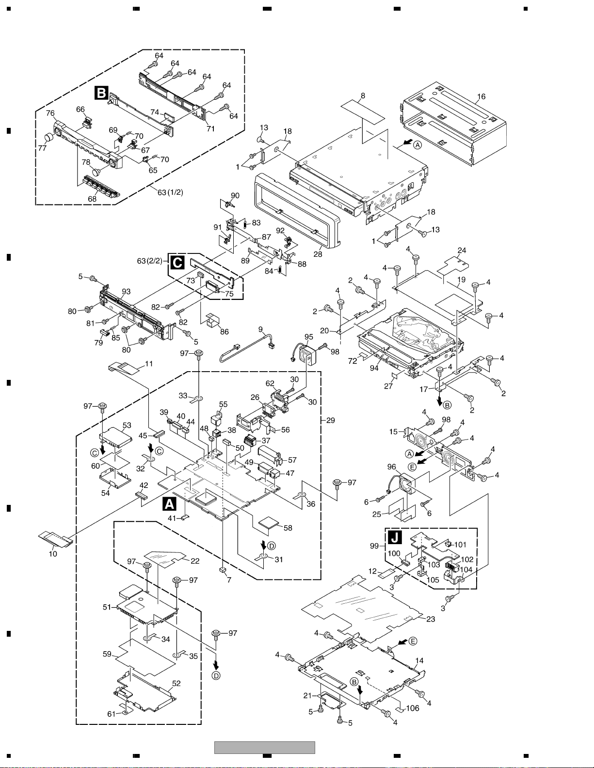
2.3 NAVIGATION UNIT (1)
A
B
C
D
E
F
16
1234
AVIC-N2/XU/UC

5678
NAVIGATION UNIT (1) SECTION PARTS LIST
Mark No. Description Part No.
1 Screw BMZ20P030FZK
2 Screw(M2x3) CBA1527
3 Screw BMZ26P025FTC
4 Screw BMZ26P040FTC
5 Screw(M2x2.5) CBA1615
6 Screw(M2.6x12) CBA1620
7 Spacer CNM9200
8 Label(EW model) VRW1860
9 Cord Assy CDE7401
10 FFC CDE7740
11 FFC CDE7403
12 FFC CDE7727
13 Screw CMZ50P060FTC
14 Case CNB3155
15 Panel CNB3048
16 Holder CND2812
17 Bracket CND2815
18 Bracket CND2816
19 Bracket CND2817
20 Bracket CND1947
21 Holder CND1948
22 Insulator CNM8043
23 Insulator CNM8571
24 Insulator CNM8715
25 Cover CNM8874
26 IC(IC2405) PAL007A
27 Spacer CNM9246
28 Panel CNS7797
29 CC Unit(UC model) CWM9948
CC Unit(EW model) CWM9947
30 Screw BMZ26P160FTC
31 Terminal(CN100) CKF1064
32 Terminal(CN604) CKF1064
33 Terminal(CN605) CKF1064
34 Terminal(CN614) CKF1064
35 Terminal(CN615) CKF1064
36 Terminal(CN2601) CKF1064
37 Connector(CN802) CKM1332
38 Connector(CN2552) CKS1940
39 Connector(CN971) CKS4822
40 Connector(CN608) CKS3751
41 Connector(CN2701) CKS3810
42 Connector(CN2) CKS4052
43 •••••
44 Connector(CN609) CKS4068
45 Connector(CN607) CKS4132
46 •••••
47 Connector(CN692) CKS4473
48 Connector(CN2551) VKN1928
49 Connector(CN731) CKS4646
50 Connector(CN691) CKS4814
51 Shield CND2822
52 Shield CND2823
53 Shield CND1951
54 Shield CND1952
No. Description Part No.
Mark
57 Holder CND1955
58 Sheet CNM7902
59 Insulator CNM8572
60 Insulator CNM8573
61 Insulator CNM8856
62 Heat Sink CNR1739
63 Detach Grille Assy(UC model) CXC4305
Detach Grille Assy(EW model) CXC4304
64 Screw BPZ20P080FZK
65 Button(DETACH) CAC8431
66 Button(SRC) CAC8432
67 Button(EQ) CAC8433
68 Button CAC8434
69 Button(RESET) CAC8503
70 Spring CBH2680
71 Cover CNS7759
72 Sheet CNM9576
73 Connector(CN5901) CKS3965
74 Connector(CN5501) CKS4657
75 Connector(CN5902) CKS4658
76 Sub Grille Unit(UC model) CXC4636
Sub Grille Unit(EW model) CXC4635
77 Knob Unit(VOLUME) CXC4641
78 Knob Unit(SELECT) CXC4642
79 Button CAC9276
80 Screw(M2x4) CBA1734
81 Screw(M2.6x2.5) CBA1777
82 Screw(M2x4) CBA1778
83 Spring CBH2681
84 Spring CBH2682
85 Spring CBH2790
86 FFC CDE7405
87 Holder CND1840
88 Holder CND1841
89 Insulator CNM8510
90 Arm CNV8571
91 Arm CNV8572
92 Arm CNV8573
93 Panel Unit CXC2693
94 DVD Mechanism Module(MS3) CXK6325
95 Fan Motor(M100) CXM1284
96 Fan Motor(M101) CXM1289
97 Screw ISS26P050FTC
98 Screw PMZ20P160FTC
99 Mother Tuner Unit(UC model) CWM9946
Mother Tuner Unit(EW model) CWM9945
100 Connector(CN2801) CKS4871
101 Connector(CN2802) CKS4822
102 Connector(CN2803) CKM1365
103 Connector(CN2804) CKS4752
104 Holder CND1956
105 Holder CND2824
106 Sheet CNM9536
A
B
C
D
E
F
55 Holder CND1953
56 Holder CND1954
56
AVIC-N2/XU/UC
7
8
17
1234
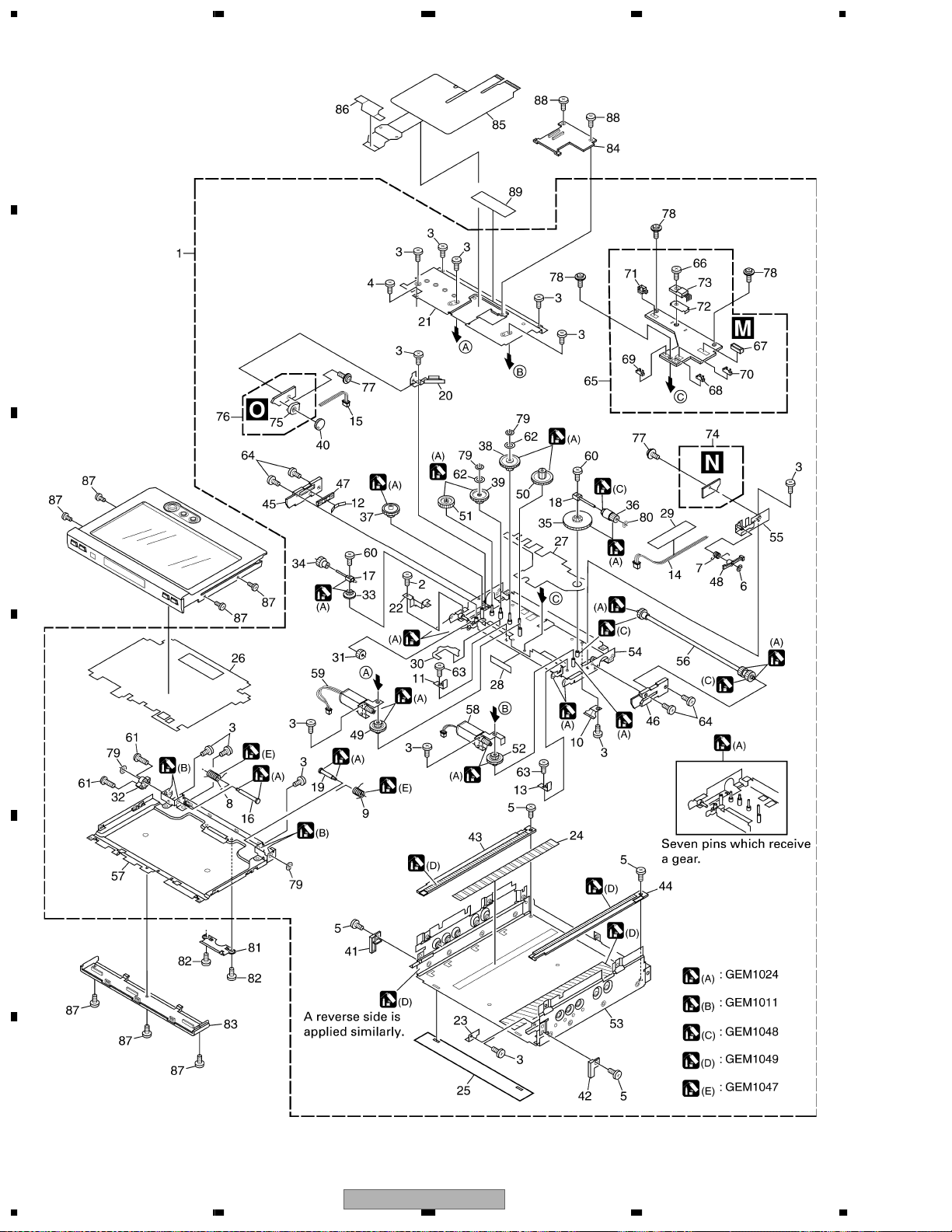
2.4 NAVIGATION UNIT (2)
A
B
C
D
E
F
18
1234
AVIC-N2/XU/UC

5678
NAVIGATION UNIT (2) SECTION PARTS LIST
Mark No. Description Part No.
1 Drive Unit CXB9508
2 Screw(M2x3) CBA1082
3 Screw(M2x2.5) CBA1250
4 Screw(M2x4) CBA1277
5 Screw(M2x1.5) CBA1615
6 Washer CBF1038
7 Spring CBH2645
8 Spring CBH2646
9 Spring CBH2647
10 Spring CBL1585
11 Spring CBL1586
12 Spring CBL1587
13 Spring CBL1642
14 Cord Assy CDE7047
15 Cord Assy CDE7213
16 Shaft CLA4270
17 Shaft CLA4305
18 Shaft CLA4306
19 Shaft CLA4309
20 Bracket CND1221
21 Case CND1229
22 Holder CND1318
23 Holder CND1449
24 Sheet CNM8522
25 Sheet CNM8037
26 Insulator CNM8048
27 Insulator CNM8158
28 Sheet CNM8159
29 Tape CNM8160
30 Insulator CNM8294
31 Gear CNR1664
32 Gear CNR1665
33 Gear CNR1677
34 Gear CNR1678
35 Gear CNR1679
36 Gear CNR1680
37 Gear CNR1688
38 Gear CNR1708
39 Gear CNR1709
40 Gear CNV7383
No. Description Part No.
Mark
51 Gear CNV7524
52 Gear CNV7529
53 Chassis Unit CXB9509
54 Frame Unit CXB9511
55 Holder Unit CXB9512
56 Shaft Unit CXB9513
57 Holder Unit CXB9514
58 Motor Unit(M3001)(Position) CXB9515
59 Motor Unit(M3002)(Angle) CXB9516
60 Screw CZB3082
61 Screw CZB3083
62 Washer CZB3084
63 Screw(M2x1.8) CZB3085
64 Screw(M2x4) CZB3088
65 Main Unit CZW3087
66 Screw BMZ26P050FTC
67 Connector(CN3801) CKS4068
68 Connector(CN3802) CKS4732
69 Connector(CN3803) CKS4732
70 Connector(CN3807) CKS4733
71 Connector(CN3809) CKS4733
72 Heat Sink CND1228
73 IC(IC3801) BA00AST
74 SW Unit CZW3088
75 Volume(VR3841) CCW1025
76 Volume Unit CZW3089
77 Screw IMS20P020FTC
78 Screw IMS20P030FZK
79 Washer YE15S
80 Washer CZB3089
81 Holder CND2813
82 Screw JFZ20P022FNI
83 Cover CNS7760
84 Holder CNV8569
85 Flexible PCB CNP7621
86 Shield CNM8969
87 Screw(M2x2) CBA1753
88 Screw(M2x3) CBA1797
89 Sheet CNM9201
A
B
C
D
E
41 Holder CNV7384
42 Holder CNV7385
43 Rack CNV7386
44 Rack CNV7387
45 Slider CNV7388
46 Slider CNV7389
47 Holder CNV7390
48 Arm CNV7391
49 Gear CNV7522
50 Gear CNV7523
56
AVIC-N2/XU/UC
F
7
8
19
1234
2.5 NAVIGATION UNIT (3)
A
B
C
D
E
F
20
1234
AVIC-N2/XU/UC

5678
NAVIGATION UNIT (3) SECTION PARTS LIST
Mark No. Description Part No.
1 Screw BPZ20P060FTC
2 Button(NAVI/AV) CAC8427
3 Button(NAVI MENU) CAC8428
4 Button(OPEN/CLOSE) CAC8430
5 Button(DISP,PGM)(UC model) CAC8504
Button(DISP,TA)(EW model) CAC8429
6 LCD CAW1870
7 FFC CDE7488
8 Holder CND2010
9 Holder CND2825
A
10 Insulator CNM8616
11 Spacer CNM8707
12 Sheet CNM8858
13 Cushion CNM9148
14 Lighting Conductor CNV8570
15 Touch Panel CSX1083
16 Screw(M2x2.5) CBA1615
17 FFC CDE7196
18 Holder CND2418
19 Sheet CNM7784
20 Insulator CNM8031
21 Sheet CNM8265
22 Conductor CNM8857
23 Monitor Unit(UC model) CWM9950
Monitor Unit(EW model) CWM9949
24 Connector(CN4801) CKS3991
25 Connector(CN4005) CKS4054
26 Connector(CN4301) CKS4054
27 •••••
28 Connector(CN5002) CKS4428
B
C
D
29 Connector(CN4003) CKS4595
30 Connector(CN5001) CKS4595
31 Connector(CN4681) CKS4675
32 Connector(CN4002) CKS4793
33 Connector(CN4701) CKS4818
34 LCD Panel CWX3056
35
Display Sub Grille Unit(UC model)
Display Sub Grille Unit(EW model)
56
CXC4634
CXC4633
AVIC-N2/XU/UC
E
F
7
8
21
1234
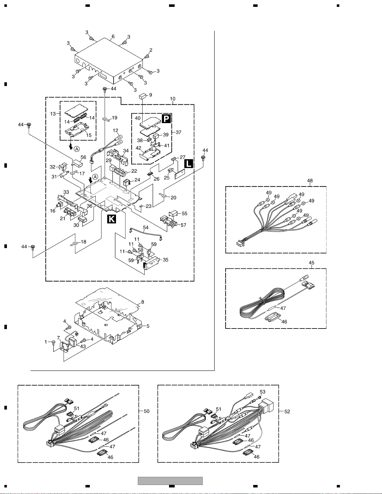
2.6 HIDEAWAY UNIT AND CORD ASSY
A
B
C
D
E
F
22
1234
AVIC-N2/XU/UC

5678
HIDEAWAY UNIT AND CORD ASSY SECTION PARTS LIST
Mark No. Description Part No.
1 Screw BMZ26P030FTC
2 Screw BMZ26P060FZK
3 Screw BSZ26P060FTC
4 Screw(M2.6x12) CBA1620
5 Chassis CNA2697
6 Case(UC model) CNB3154
Case(EW model) CNB3153
7 Holder CND2821
8 Insulator CNM8565
9 Gasket CNM8954
10 Mother Tuner Unit(UC model) CWM9946
Mother Tuner Unit(EW model) CWM9945
11 Screw BMZ26P060FTC
12 Cord Assy CDE7397
13 FM/AM Tuner Unit(UC model) CWE1651
FM/AM Tuner Unit(EW model) CWE1650
14 Connector(CN101,102) CKS4653
15 Holder CND1432
16 Pin Jack(CN1351) CKB1065
17 Terminal(CN1401) CKF1064
No. Description Part No.
Mark
47 Resistor RS1/2PMF102J
48 Cord Assy CDE7399
49 Cap CNV6727
50 Cord Assy(UC model) CDE7487
> 51 Fuse(10A) CEK1136
52 Cord Assy(EW model) CDE7486
53 Cap(EW model) CKX-003
54 Cord(EW model) CDH1332
55 Shield(EW model) CND2814
56 Shield(EW model) CND1964
57 Tuner Unit(Y1801)(EW model) CWE1674
58 Transistor(Q1907) 2SB1629
59 Transistor(Q1908,1909) 2SD2396
A
B
C
18 Terminal(CN1403) CKF1064
19 Terminal(CN1903) CKF1064
20 Terminal(CN1904) CKF1064
21 Pin Jack(CN1301) CKB1071
22 Pin Jack(CN1701) CKB1071
23 Connector(CN1950) CKS4822
24 Connector(CN1101) CKS3414
25 Connector(CN551) CKS5205
26 Connector(CN1841) CKS5205
27 Connector(CN552) CKS5204
28 •••••
29 Connector(CN1201) CKS4590
30 Connector(CN1001) CKS4646
31 Antenna Jack(CN1402) CKX1056
32 Holder CND2818
33 Holder CND1901
34 Holder CND1902
35 Holder CND2819
36 Holder CND2820
37 GPS Unit(UC model) CWX2960
GPS Unit(EW model) CWX2929
38 Connector(CN461) CKS4280
39 Connector(CN504) CKS4432
40 Shield CNC9192
41 Holder CNC9252
D
E
42 Shield CND1161
43 Fan Motor(M102) CXM1293
44 Screw ISS26P060FTC
45 Cord CDE6825
46 Cap CNS1472
56
AVIC-N2/XU/UC
F
7
8
23
1234
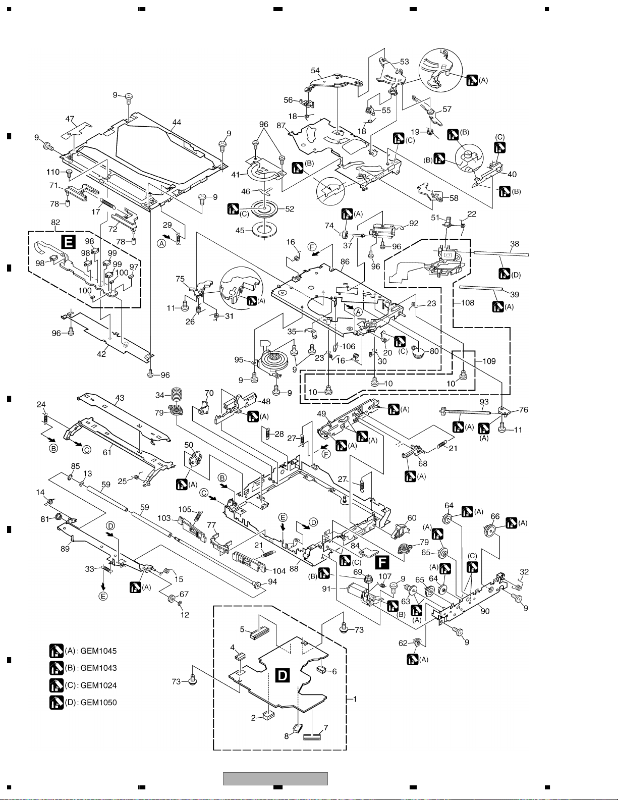
2.7 DVD MECHANISM MODULE
A
B
C
D
E
F
24
1234
AVIC-N2/XU/UC

5678
DVD MECHANISM MODULE SECTION PARTS LIST
Mark
No. Description Part No.
1 DVD Core Unit(MS3) CWX2941
2 Connector(CN1501) CKS4282
3 Connector(CN1401) CKS4052
4 Connector(CN1202) CKS4624
5 Connector(CN1611) CKS4052
6 Connector(CN1603) CKS4374
7 Connector(CN1101) CKS4625
8 Connector(CN1201) CKS4067
9 Screw BMZ20P020FTC
10 Screw(M2 x 3.5) CBA1571
11 Screw(M2 x 2.5) CBA1623
12 Washer CBF1038
13 Washer CBF1064
14 Spring CBH2586
15 Spring CBH2587
16 Spring CBH2588
17 Spring CBH2589
18 Spring CBH2590
19 Spring CBH2591
20 Spring CBH2592
21 Spring CBH2593
22 Spring CBH2594
23 Spring CBH2595
24 Spring CBH2596
25 Spring CBH2597
26 Spring CBH2598
27 Spring CBH2599
28 Spring CBH2600
29 Spring CBH2601
30 Spring CBH2602
31 Spring CBH2603
32 Spring CBH2604
33 Spring CBH2605
34 Spring CBH2711
35 Spring CBL1564
36 •••••
37 Shaft CLA3881
38 Shaft CLA4206
39 Shaft CLA4207
40 Lever CNC9933
41 Holder CNC9939
42 Holder CND2251
43 Holder CNC9941
44 Frame CND2250
45 Sheet CNM6883
46 Sheet CNM8283
47 Sheet CNM8643
48 Lever CNV8076
49 Lever CNV7155
50 Cam CNV7156
51 Rack CNV7157
52 Clamper CNV7158
53 Arm CNV7159
54 Arm CNV7160
55 Arm CNV7161
No. Description Part No.
Mark
* 57 Arm CNV7163
58 Arm CNV7164
59 Roller CNV7165
60 Arm CNV7166
61 Guide CNV8093
62 Gear CNV7169
63 Gear CNV7170
64 Gear CNV7171
65 Gear(Black) CNV7172
66 Gear CNV7173
67 Gear CNV7174
68 Rack CNV7175
69 Gear CNV7176
70 Arm CNV8077
71 Lever CNV7178
72 Lever CNV7179
73 Screw IMS20P030FTC
74 Gear CNV7181
75 Holder CNV7183
76 Holder CNV7184
77 Guide CNV7745
78 Roller CNV7344
79 Damper CNV7470
80 Damper CNV7471
81 Collar CNV7645
82 Compound Unit(A) CWX3154
83 •••••
84 Compound Unit(B) CWX3156
85 Washer YE20FTC
86 Chassis Unit CXC3629
87 Arm Unit CXB8681
88 Frame Unit CXB8683
89 Arm Unit CXC4701
90 Bracket Unit CXB8685
91 Motor Unit(LOADING)(M1) CXC4659
92 Motor Unit(CARRIAGE)(M2) CXC4314
93 Screw Unit CXB8689
94 Roller Unit CXB8690
95 Motor(SPINDLE)(M3) CXM1308
96 Screw JFZ20P018FTC
97 Photo-transistor(Q1299) CPT231SCTD
Spring Switch(S1201,1202,1203) CSN1069
98
99 Spring Switch(S1204,1205) CSN1070
100 Resistor(R1298,1299) RS1/16S0R0J
101 •••••
102 •••••
103 Arm CNV7742
104 Arm CNV7743
105 Spring CBH2710
106 Spring CBL1643
107 Spring CBH2712
108 Pickup Unit(Service)(Screw) GXX1234
109 Screw Assy CXX1750
110 Screw(M1.4 x 1.4) CBA1787
A
B
C
D
E
F
56 Arm CNV7162
56
AVIC-N2/XU/UC
7
8
25
7
T
I
S
I
S
1234
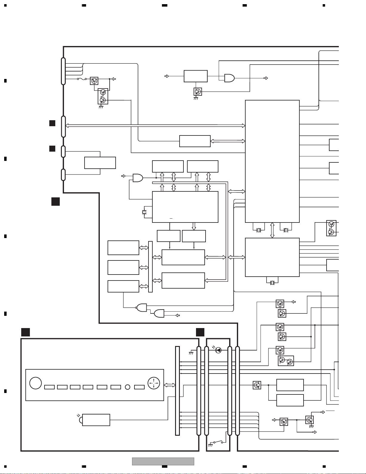
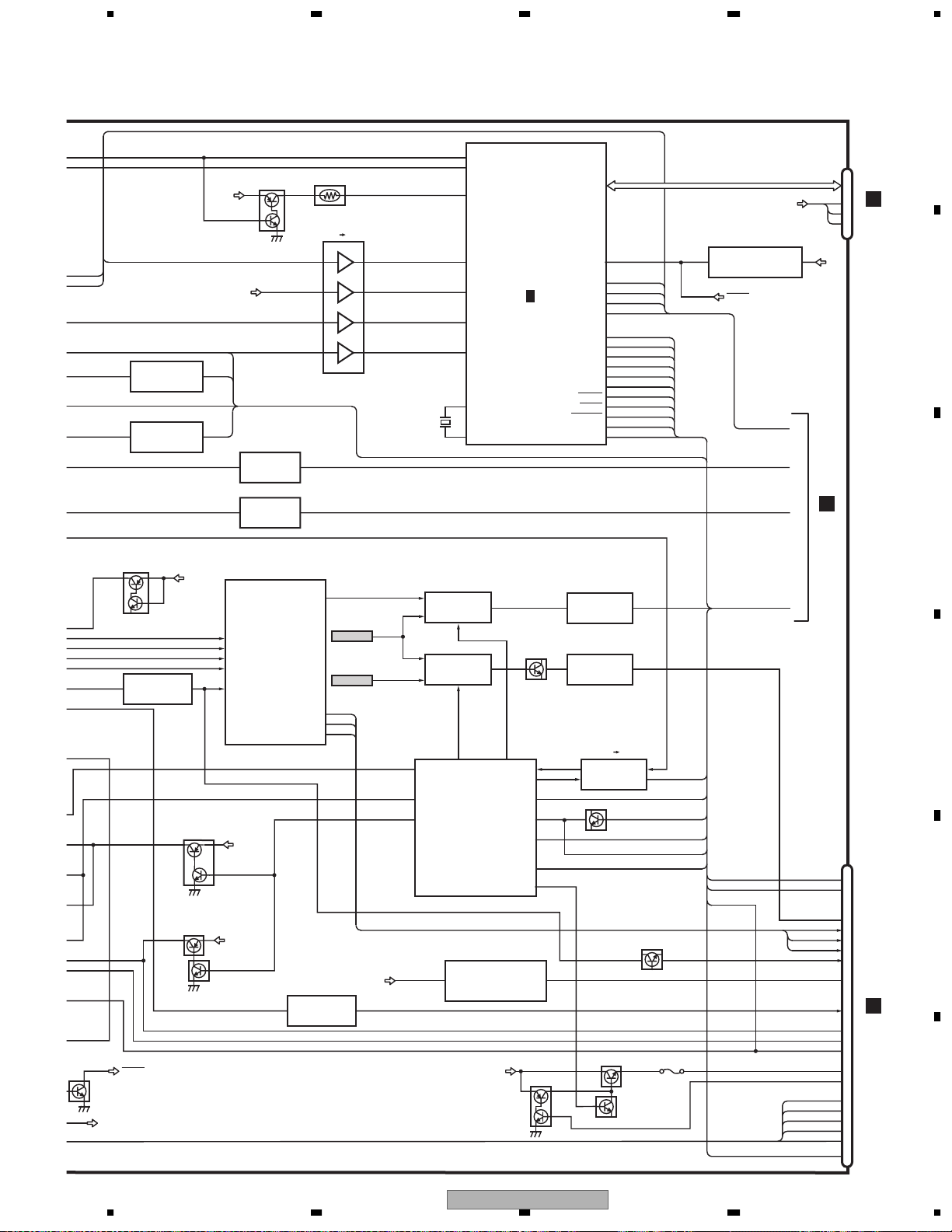
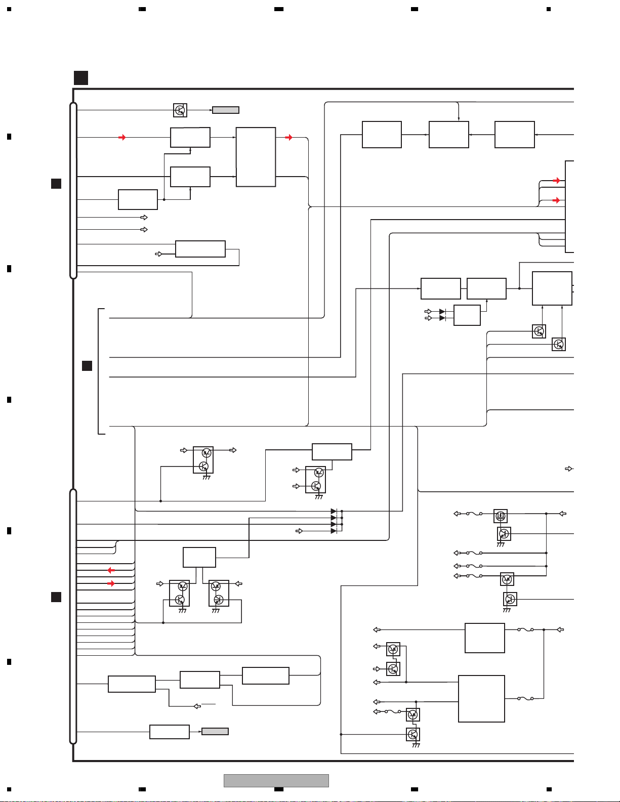
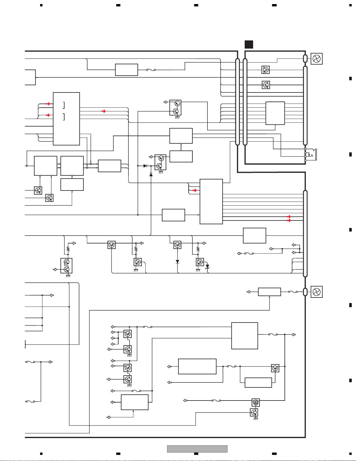
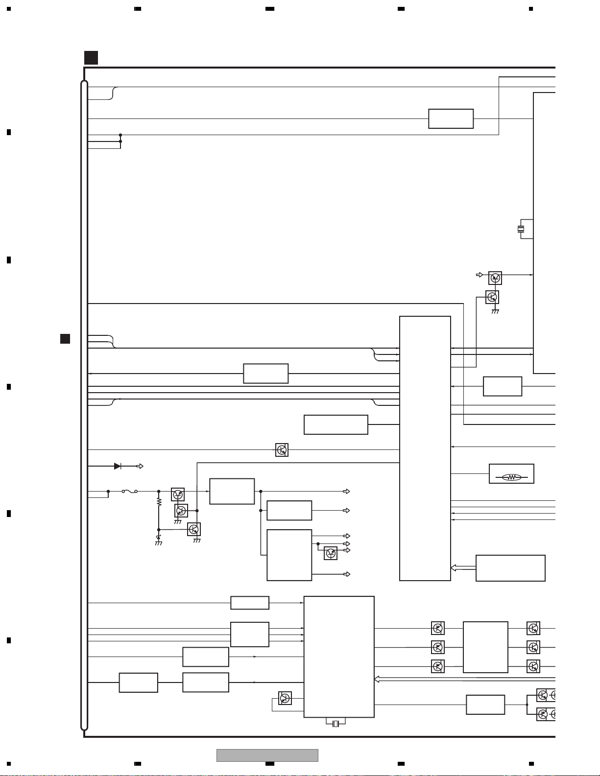
3. BLOCK DIAGRAM AND SCHEMATIC DIAGRAM
3.1 BLOCK DIAGRAM
A
CN692
CTOEX
4
EXTOC
TELE ATLAS/
DEBUG
5
CTOTA
7
TATOC
8
9
FU691
Q691
2SD1767
Q692
IMD3A
BACKUP2
CCD3
RESET DIRECT
IC 301
26
M51957BFP
5
Q301
DTC114EU
SYSRST
CN2
B
C
D
B
KEYBOARD PCB
E
(S5510) ENT
F
CN1401
CN1501
DIGITAL OUT
VOL
f
SRC
(S5504)
D
CN2551
D
1
CN2552
4
A
CC UNIT (1/2)
kqi nm
REAR
(S5505)
(S5508)
DIGI IN
2
IC 2551
TC7WT125FU
3
WIDE
ANGLE
(S5509)
(S5502,5503)
REMOCON
IC 5501
SBX3050-01
RST3
30,000MHZ
FLASH ROM
IC 110
PEH005A(UC)
PEH003A(EW)
FLASH ROM
IC 111
PEH006A(UC)
PEH004A(EW)
SRAM
IC 113
M5M5V216ATP-70HI
6
+
-
og
BAND
EJECT
(S5501)
(S5507)EQ(S5506)
3
IC 4
TC7SZ08FU
2
4
1
X1
IC 112
TC7SH00FUS1
4
IC 114
TC7SH08FUS1
p
11-14
SDRAM
IC 1
K4S561632E-TL75
37
13CKE
CKB
56
X1
UPD705103GM-180S1
57
X2
R/W
105 16 18
2
IC 102
TC7SH04FUS1
4
119
TC74LCX245FTS1
(DATA BUS BUFFER)
TC74LCX541FTS1
(ADDRESS BUS BUFFER)
1
2
2
4
1
(S5511)
TELE ATLAS/DEBUG
IC 691
UPD4721GSS1
SDRAM
IC 3
HY57V561620CLT-H
37
IC 2
XCS2,4-7
IC 101
TC74LCX08FT
S1
11
IC 103-106
IC 107-109
XCS_SRAM
SRAM_CSE
RST3
C
(ILMGND)
2
REAROFF
4
REARON
6
ILMG
8
ILMA
9
REM
7
KEY0
14
KEY1
13
KEY2
12
RDTB
5
RDTA
3
CN5501
TIP
TIMING GEN
PANEL PCB
2
4
6
8
9
7
14
13
12
5
3
CN5902
IC 302
TC7SH08FUS1
2
1
ANTON
CN5901
1
7
9
11
12
10
17
16
15
8
6
2
S5901
RESET
4
RST3
SYSTEM CONTROL
MICSNS
CTOSYS
CPUWDT
CPOGPS1
PBSNS
GPSTOC1
ADC_DATA
DAC_DATA
X3
AOUTR
AOUTG
AOUTB
DCLK0
CSYNC
DLED
Q2705
2SA1577
IC2701
IC2702
EXTAL1
S
GV
VDD5
Q2704
UMH1N
143,142,65
96
27
127
29
126
30
63
55
49
129
152 AOUTRED
147
143
202
204
207
ADC_GCNT0-2
125
ANTON1
IC 5
PD6336C
14
REM_IN
11
XCS_SRAM
44
SRAM_CSE XCCSTBY
XTAL0
EXTAL0
XTAL1
X2
30.000MHz
MB86291APFVS-G-DL
REM_IN
CN2701
DFLED
1
REAROFF
7
REARON
9
ILMG
11
ILMA
12
Q2701
DTC114TU
REM REM0
10
KEY0
17
KEY1
16
KEY2
15
RDT0
8
RDT1
6
RESET
2
58 60
33.8688MHz
IC 201
SCARLET
CLK OSCOUT
124 128
14.31818MHz
Q2714
2SA1576
Q2716
DTC124EU
Q2703
2SA1577
Q2702
DTC144EU
1,2
2
VDD
X202
TC7SH08FUS1
TC7SH14FUS1
Q602(1/2)
UMD2N
CTOSYS
CPUWDT
CTOGPS
PKBSNS
GPSTOC
XCCSTBY
AOUTGREEN
AOUTBLUE
FSC
OUTCSYNC
OVER
4
4
Q602(2/2)
UMD2N
RESETM
1,2
DISCSET
1,2
4
Q201
UMD2N
TC7SE
RESET
TC7
TC7
IC
26
1234
AVIC-N2/XU/UC
5678
A
,142,65
CTOSYS
CPUWDT
CTOGPS
PKBSNS
GPSTOC
XCCSTBY
AOUTRED
AOUTGREEN
AOUTBLUE
FSC
OUTCSYNC
OVER
N
REM0
Q602(2/2)
UMD2N
DISCSET
1,2
4
UMD2N
1,2
RESET
RESETM
IC604
TC7SH08FUS1
IC605
TC7SH08FUS1
Q201
IC757
TC7SET08FUS1
CCON
CCD3C
4
Q2706
IMD2A
Q2708
2SA1577
Q621
RST3
IMD2A
9,10 8
12,13 11
VDD5S
4
TC74VHCT08AFTS1
1,2
ADC
9 2 ONSEIMIC
IC 305
AK5381VT
DAC
411
IC 304
AK4351VT
RGB 75W DRIVER
NTSC ENCORDING
CVOUT
2
RIN
3
IC 751
GIN
4
CXA1645M
BIN
6
SCIN
10
SYNL
ROUT
GOUT
BOUT
BACKUP1
BACKUP1
Q2707
DTC144EU
1,2
TC7SZ08FU
TH601
3V 5V
4,5 6
1,2
IC602
DACOUTL
20
DVDV
from (2/2)
SELV
from (2/2)
23
22
21
IC758
3
DLED
REARON
ILMPWR
8.5V
4
SYSRST
NTEMPI
X601
10,000MHZ
CVOUT
DVDV
SELV
1
5
4
28
CCON
32
RSTOUT
MOTOR DRIVE
SYSTEM CONTROL
73
NTEMPI
7
DISC
DISC
18
RST3
RST3
22
RXN
RXN
30
CPUWDT
3
1
1
3
ARMSW
REAON
ILMPWR
CPUWDT
10
XOUT
12
XIN
REAR/FRONT
VIDEO SELECTOR LEVEL ADJ.
IC 756
NJM2235V
IC 753
NJM2235V
SYSTEM CONTROL
64
2
6
2
VFSEL
PD5937A
S-812C56AUA-C3K
37
IC 601
(2/2)
5.6V REG
UMF23N
BACKUP1
IC 810
Q830
VRSEL
XCCSTB
MUTESO
Q2713
IMD2A
IC 601 (1/2)
PD5937A
2/7
A
Q752
2SC4081
38
29
24
TSO
25
TSI
46
DSENS
51
19
AUPW
45
ILMDIM
POWER ON RESET
9
RESET
2
NFANCNT
MUTEGU
WCONT
WREMIN
51MUTE
AMPSTB
IRQPW
MUTNS
ASENS
BSENS
ILMSENS
ANTPW
NJM2561F1
4
NJM2561F1
62
53PTOH
ILMDIM
3Q830-E
NFANCNT
80
MUTEGU
62 WCONT
70 WREMIN
68
43
31
34
36
SELR
35
SELL
16
15
47
49
TELIN
61
IC 755
IC 754
3V 5V
IC 608
TC7WT125FU
Q601
2SC4081
Q2715
2SD1767
Q2717
DTC144EU
MUTE51
AMPSTB
IRQPW
MUTENS
NOSELR
NOSELL
ASENS
BSENS
ISENS
TELIN
ANTPW
2
2
Q751
2SC4081
1
S-80840CNMC-B8Z
RETV
HTOP
GNDISO
MUTESO
DSENS
AUPW
FU2701
RESET
FMONV
MTOH
HTOM
REM
MFLPW
IC 612
ONSEIMIC
DACOUTL
PWRMTR
A
B
C
D
RDT1
RDT0
CN609
2
A
(2/2)
CN608
HRX
HTX
MONVBS
ANB
ANG
ANR
CSYNC
SWAC56
ILMG
ILMA
MOREM
LCDBL
SBLPWR
RDTB
RDTA
KEY2
KEY1
KEY0
MFLPW
YS
VDD
3
2
1
24
25
39
37
36
35
33
20
27
17
18
22
19
31
30
29
10
9
8
26
M
CN3801
G
CN4002
B
C
D
E
F
56
AVIC-N2/XU/UC
7
8
27
T
A
T
4
4
3
3
Q
M
U
U
7
1
C
1234
A
A
CC UNIT (2/2)
CN607
VIDEO OUT
38
ANALOG LOUT
36
ANALOG ROUT
34
D
B
CN1611
17
18
20
24
21
29
MMUTE
VCONTB
VCONTA
SLVSTS
XRES
DISCSET
MUTE CONT
UMD2N
A
C
B
A
(1/2)
C
Q2401
ONSEIMIC
CONTB
CONTA
RST3
DACOUTL
Q754
2SC4081
MUTE
Q2402
DTC323TU
MUTE
Q2403
DTC323TU
1
IC309
2
TC7SH08FUS1
DVDV
to (1/2)
4
DVD BUFF.
9
DVD LPF
IC2407
NJM3403AV
6
ADC_GCNT0-2
ATTLPF,AMP
Q2604,2605,2607
RETL
14
&
RETR
1
IC2601(2/2)
8
NJM3403AV
DTC323TU
Q2603,2606,2608
UMD2N
LPF
ONSEIMUTE1
RESETM
IC2553
NJM2068V
5
DTC323TU
7
Q2408
UMD2N
MUTE
Q2409
MIC HPF
MIC AMP
IC2601(1/2)
NJM3403AV
MUTE
CONT
NOSELL
NOSELR
MUTENS
L,R SEP AMP
1,6
Q2414
DTC124EU
519
ELEC
SOU
42
DVDL
36
DVDR
SELL
43
35
SELR
20
MUTE
19
VST
18
VDT
17
VCK
IC2402
TC7W66FU
IC2552
NJM2068V
DTC1
IN
IN
IN
IN
M
S
D
CL
Q2
D
1,2
CPUWDT1
MUTE CONT
NJM2107F
MUTESO
OFMT
MUTEAMP
RESETM
IRQPW
IC2408
5
Q2410
UMD2N
43
DVD8
(300mA)
VCC5
CONTB
CCD5
AU85
8.5V
AUPW
FU807
AUPW
Q801
2SB1260
Q802
DTC114EU
Q807
2SB1260
DTC114EU
DSWBUP
PWRMTR
PWRVI
PWRFL
5V
8.5V
Q808
FU809
DTC144EU
FU808
FU806
FU801
2SA1834F5
8.0V REG
IC805
TPS5103IDB
Q811
RK4936
8.5V, 5V REG
28
IC803
TPS5102IDBT
18
Q815,819
RK4936
RSQ030P03
Q806
Q821
Q822
DTC114EU
Q805
DSENS
MFLPWR
FU802
FU804
I
BUP
B
BA
Q731
IMD3A
VDD5
D
CN731
MUTEVOL
17
MUTEAMP
18
VST
9
VDT
10
VCK
11
RETR
1
RETL
2
SELR
4
SELL
5
GNDISO
E
F
K
CN1001
6
21
22
23
24
25
12
13
14
26
16
7
BSENS
REM
MTOH
HTOM
HTOP
CTOGPS
GPSTOC
RETV
PTOH
RQ
SELV
4
TC7SH00FUS1
IC613
VDD
AMPSTB
3
NJM2137V
2
1
UMD2N
AMP
IC752
Q2421
4
TC7S04FU
Q2422
2SC4081
IC611
RESET
1
SELV
Q2419
UMD2N
to (1/2)
2
1
SWACPW
MBUP
4
IC603
TC7SH08FUS1
CCD5
AU85
RESETM
28
1234
AVIC-N2/XU/UC
5678
HPF
MP
(1/2)
03AV
1,6
Q2414
DTC124EU
5
ELECTRONIC VOLUME/
SOURCE SELECTOR
PML009A
42
DVDL
IN3_L
36
DVDR
IN3_R
SELL
43
IN4_L
35
SELR
IN4_R
20
MUTE
MUTE
19
VST
STB
18
VDT
DATA
17
VCK
CLK
L,R SEP AMP
IC2402
IC2552
7
1
Q2415
DTC124EU
TC7W66FU
NJM2068V
IC2401
MUTE
Q2417
Q2418
DTC323TU
Q2416
UMD2N
MUTE
NFANCNT
RR
11
RL
22
PR
12
PL
10
FL
24
FR
CONT
NAVI FAN
Q823-825
835
Q823,825,835
2SC4081
SWR
SWL
AUDIO/GUIDE
MIXAMP
IC2404
914
NJM2058V
61
Q824
2SB1184F5
RR23
RL
MBUP
FL
FU803
MIXIN
MBUP
Q2611
UMD2N
MUTE CONT
Q2427,2428
DTC124EU
Q2610
UMD2N
MUTERCA
GUIDE SP AMP
IC2403
2
TDA7052BT
4
MUTE
Q2420
DTC114EU
5
8
FRFR11
FL
RL
RR
12
14
15
22
AUDIO AMP
IC2405
PAL007A
MUTE
MICIN
MUTEGU
WCONT
WREMIN
SWL
SWR
MUTERCA
ONSP+
ONSP-
25
5
7
9
17
19
21
23
J
RELAY PCB
CN2802
CN2801CN691
CCFANCCFAN
20
20
MICSNSMICSNS
22
22
MIC
12
12
MUTEGU
4
4
WCONT
14
14
WREMIN
15
15
FL
FL
1
1
RL
RR
FR
RL
2
2
SWL
3
3
SWR
6
6
RR
7
7
FR
8
8
MUTERCA
10
10
ONSP+
16
16
ONSP-
17
17
B.REMOTEBREM
19
19
Q2801
2SC4081
Q2886
2SC4081
MUTE
Q2831-2833
Q2844-2846
DTC323TU
CCFAN
CN2803
GUIDEON
WREM SEL
WREM AN
BREM
MICR
MICL
PRE L
PRE R
2
17
19
18
14
15
FL
9
RL
5
1
3
RR
7
FR
11
13
3
2
FAN
MOTOR
EXTENSION
CN2804
B
GUIDE
SPEAKER
OUT
CN802
A
FL-3
FL+
FRFR+
RR+
RRRL+
RL-
1
3
5
7
8
6
4
2
C
DSENS
MFLPWR
FU802
FU804
BUP
Q828
IMX1
BUP
BACKUP2
BSENS
DSENS
VDD5
MFLPWR
PKBSNS
Q840
2SA1576
SD3VC
CCD3C
VDD33
CCD5C
SRVDD33
VCC33
CONTB
CCD25C
VCC18
CONTA
MUTE51
ISENS
Q951
DTC114EU
P. B
Q809
2SA1797
CCD3
Q810
DTC114EU
Q803
2SA1834F5
Q804
DTC114EU
FU811
IC801
31
PQ018EZ01ZP
2
CCD5
ILL
FU813
1.8VREG
BUP3C
VDD5
Q704
2SA1576
TELIN
5
DSWVDD
ASENS
VDD5
Q837
2SC4081
MUTE
3V REG
IC806
S-L2980A33MC-C6S
ACC
3.3V
2.5V
FU812
1,3
ANTPW
BACKUP1
3.3V,2.5V REG
28
TPS5102IDBT
18
FU814
DSENS
IC807
TPD1018F
6
Q839
UMD2N
FU810
BACKUP2
AUPW
IC804
Q816,820
RK4936
5.6V REG
3
S-812C52AUA-C3G
RSQ030P03
BACKUP2
11
IC808
Q832
DTC144EU
1
FAN DRIVE
Q971-973
Q971
IMX2
Q972
IMD3A
Q973
2SD1767
FU805
Q829
2SB1184F5
2
Q838
MBUP
BUP
CN971
FU971
A.ANT
MUTE
ACC
BUP
ILL
P. B
Vehicle
12
15
14
13
11
9
MOTOR
2
I/F
D
FAN
E
F
56
AVIC-N2/XU/UC
7
8
29
C
T
4
3
1234
G
A
B
MONITOR PCB
CN4002
VILMG
16
VILMA
17
REMCON
20
PWRFL
1
PWRFL
2
PWRFL
3
1,2
TC7SH08FU
IC4702
4
S1
X4701
4.97MHz
17
REM
L
CON
IC
PD6
22
X0
23
X1
VCC
LCDBL
18
76
77
78
9
8
10
63
64
60
62
13
MONITOR
SYSTEM
CONTROL
KEY1
KEY2
TXD
RXD
MFLPW
ROT0
ROT1
RESET
PE5413B
VDDSENS
MVIPW
LSWVDD
IC4601
TEMPSEN
Q4153(1/2)
Q4152(1/2)
Q4151(1/2)
LKYDTKEY0
LDPDT
DIMMER
INVPUL
INVBST
LSEN
PNLYV
PNLXV
PNLADX
PNLADY
11
12
30
DIMMER
5
44
43
2
LSEN
IC4901
NJM2903V
TEMP SENS
80
25
24
1
3
46-50
S-93C46BR0I-J8T1
Q4151-4156
UMZ1N
6
RGB AMP
2
IC 4151
NJM2138V
13
VCOM AMP
61
IC 4181
NJM082BV
C
KEY0
8
KEY1
A
9
KEY2
10
CN608
HRX
21
HTX
22
MFLPW
23
ROT0
25
ROT1
26
SWACPW
D
13
19
14
15
SWAC56
PWRVI
PWRVI
FU4831
VSW5V
Q4831
2SB1260
Q4833
2SC4617
Q4832
DTC114EK
4
V REG
IC4851
R1224N102H
Q4851
CPH6316
IC4212
TC7SH08FU
E
35
33
32
31
24
29
MONVBS
Q4111,4113,4121,4123,4131,4133
ANB
ANG
ANR
YS
CSYNC
TK15404AMI
FILTER
IC 4142
2SC4617
Q4101
2SC4617
2SA1774
1,2 4IC 4061
TC7SH08FUS1
1,232 4IC 4141
TC7SH08FUS1
Q4102
2SC4617
Q4112,4122,4132
2SA1774
FILTER
Q4103
FILTER
Q4101-4103
FILTER
Q4111-4113
Q4121-4123
Q4131-4133
2SC4617
F
1,2
S1
Q4603
2SC4617
REG.
IC4841
R1130H251B
REG.
IC4861
4
MAX1748EUES1
Q4002
RESET
IC4602
S-80835CNNB-B8U
12
7
15
Q4835
2SD1664
8
65
CVI1
BIN
GIN
TC90A64AF-P
RIN
FNAVI
HDIN
CDAO
CKIN
XO
82
OSD
IC 4001
54
53
52
93
18
72
74
XI
83
VCC(V33)
VCC(V25)
VCC(V18)
VCC(V8)
VCC(V5)
VCC(VM12)
ROUT
GOUT
BOUT
POLC
1
34
36
38
28
4741
Q
23JK
DTA1
4742
Q
DTC124EK
TH4601
EEP ROM
IC4651
7
1
14
UMT2N
10
20
18
76
PNLYV
PNLXV
PNLADX
PNLADY
Q4153(2/2)
Q4152(2/2)
Q4151(2/2)
Q4183
VLCD
KYDT
DPDT
X4001 42MHz
30
1234
AVIC-N2/XU/UC
 Loading...