

Page 1

Installation Manual
Manuel d’installation
NAVIGATION AV SYSTEM
SYSTEME DE NAVIGATION AV
SISTEMA DI NAVIGAZIONE AV
SISTEMA DE NAVEGACIÓN AV
NAVIGATIONS-/AV-SYSTEM
AV NAVIGATIESYSTEEM
AVIC-F60DAB
AVIC-F960DAB
AVIC-F960BT
English NederlandsDeutschEspañolItalianoFrançais
Page 2

Contents
Precautions
Your new product and this manual 3
Important safeguards 3
Connection
Precautions before connecting the
system 5
Before installing this product 5
To prevent damage 6
– Notice for the blue/white lead 6
Parts supplied 7
Connecting the power cord (1) 8
Connecting the power cord (2) 10
Connecting the system 12
Connecting to separately sold power
amp 13
Attaching identification labels to USB
cables 14
Connecting an iPhone with Lightning
connector 14
– Connecting via the USB port 14
– Connecting via the HDMI port 15
Connecting an iPhone with 30-pin
connector 15
– Connecting via the AUX input 15
– Connecting via the RGB input 16
Connecting the Android™ device 16
– Connecting an Android device with an
HDMI port 16
– Connecting an Android device with an
MHL port 17
Connecting the MirrorLink™ device 17
Securing the High Speed HDMI
Connecting a rear view camera 18
Connecting the external video
component 19
– Using AV input 19
– Using an AUX input 20
Connecting an HDMI device 21
R
Cable 18
Connecting the rear display 22
– When using a rear display connected to
rear video output 22
Installation
Precautions before installation 23
To avoid electromagnetic interference 23
Before installing 23
– For AVIC-F60DAB users 24
Installing this product 24
– Installation notes 24
– Parts supplied 25
– Before installing this product 25
– Installation with the holder 25
– Installation using the screw holes on
the side of this product 26
Installing the GPS aerial 27
– Installation notes 27
– Parts supplied 27
– When installing the aerial inside the
vehicle (on the dashboard or rear
shelf) 28
Installing the microphone 29
– Parts supplied 29
– Mounting on the sun visor 29
– Installation on the steering column 30
– Adjusting the microphone angle 30
After installation
After installing this product 31
2
Engb
Page 3
Precautions
Your new product and this
manual
! The navigation features of this product
(and the rear view camera option if purchased) are intended solely to aid you in
the operation of your vehicle. It is not a substitute for your attentiveness, judgement
and care when driving.
! Never use this product to route to hospi-
tals, police stations, or similar facilities in
an emergency. Please call the appropriate
emergency number.
! Do not operate this product, any applica-
tions, or the rear view camera option (if purchased) if doing so will divert your attention
in any way from the safe operation of your
vehicle. Always observe safe driving rules
and follow all existing traffic regulations. If
you experience difficulty in operating this
product or reading the display, park your
vehicle in a safe location and apply the
handbrake before making the necessary
adjustments.
! This manual explains how to install this
product in your vehicle. Operation of this
product is explained in the separate manuals.
! Do not install this product where it may (i)
obstruct the driver’s vision, (ii) impair the
performance of any of the vehicle’s operating systems of safety features, including
airbags, hazard lamp buttons, or (iii) impair
the driver’s ability to safely operate the vehicle. In some cases, it may not be possible
to install this product because of the vehicle type or the shape of the vehicle interior.
Section
01
English
Important safeguards
WARNING
Pioneer does not recommend that you install
this product yourself. This product is designed for professional installation only. We
recommend that only authorised Pioneer service personnel, who have special training
and experience in mobile electronics, set up
and install this product. NEVER SERVICE
THIS PRODUCT YOURSELF. Installing or
servicing this product and its connecting
cables may expose you to the risk of electric
shock or other hazards, and can cause damage to this product that is not covered by
warranty.
! Read this manual fully and carefully before
installing this product.
! Keep this manual handy for future refer-
ence.
! Pay close attention to all warnings in this
manual and follow the instructions carefully.
! This product may in certain circumstances
display inaccurate position of your vehicle,
the distance of objects shown on the
screen, and compass directions. In addition, the system has certain limitations, including the inability to identify one-way
streets, temporary traffic restrictions and
potentially unsafe driving areas. Please exercise your own judgement in the light of
actual driving conditions.
! As with any accessory in your vehicle’s in-
terior, this product should not divert your
attention from the safe operation of your
vehicle as it may result in serious injury or
death. If you experience difficulty in operating the system or reading the display,
please make adjustments while safely
parked.
! Please remember to wear your seat belt at
all times while operating your vehicle. If
you are in an accident, your injuries can be
considerably more severe if your seat belt
is not properly fastened.
Engb
3
Page 4

Section
01
Precautions
! Certain country and government laws may
prohibit or restrict the placement and use
of this product in your vehicle. Please comply with all applicable laws and regulations
regarding the use, installation and operation of this product.
4
Engb
Page 5
Connection
Section
02
Precautions before
connecting the system
WARNING
Do not take any steps to tamper with or disable the handbrake interlock system which
is in place for your protection. Tampering
with or disabling the handbrake interlock
system could result in serious injury or
death.
CAUTION
! If you decide to perform the installation
yourself, and have special training and experience in the mobile electronics installations, please carefully follow all of the
steps in the installation manual.
! Secure all wiring with cable clamps or
electrical tape. Do not allow any bare wiring to remain exposed.
! Do not directly connect the yellow lead of
this product to the vehicle battery. If the
lead is directly connected to the battery,
engine vibration may eventually cause
the insulation to fail at the point where
the wire passes from the passenger compartment into the engine compartment. If
the yellow lead’s insulation tears as a result of contact with metal parts, short-circuiting can occur, resulting in
considerable danger.
! It is extremely dangerous to allow cables
to become wound around the steering column or gearstick. Be sure to install this
product, its cables, and wiring away in
such so that they will not obstruct or hinder driving.
! Make sure that the cables and wires will
not interfere with or become caught in
any of the vehicle’s moving parts, especially the steering wheel, gearstick, handbrake, sliding seat tracks, doors, or any of
the vehicle’s controls.
! Do not route wires where they will be ex-
posed to high temperatures. If the insulation heats up, wires may become
damaged, resulting in a short circuit or
English
malfunction and permanent damage to
the product.
! Do not cut the GPS aerial cable to shorten
it or use an extension to make it longer.
Altering the aerial cable could result in a
short circuit or malfunction.
! Do not shorten any leads. If you do, the
protection circuit (fuse holder, fuse resistor or filter, etc.) may fail to work properly.
! Never feed power to other electronic pro-
ducts by cutting the insulation of the
power supply lead of this product and tapping into the lead. The current capacity of
the lead will be exceeded, causing overheating.
Before installing this product
! Use this unit with a 12-volt battery and ne-
gative earthing only. Failure to do so may
result in a fire or malfunction.
! To avoid shorts in the electrical system, be
sure to disconnect the (–) battery cable before installation.
Engb
5
Page 6
Section
02
Connection
To prevent damage
WARNING
! Use speakers over 50 W (output value)
and between 4 W to 8 W (impedance value).
Do not use 1 W to 3 W speakers for this
unit.
! The black lead is earth. Please earth this
lead separately from the earth of high-current products such as power amps. Do not
earth more than one product together
with the earth from another product. For
example, you must separately earth any
amp unit away from the earth of this product. Connecting earths together can
cause a fire and/or damage the products if
their earths became detached.
! When replacing the fuse, be sure to only
use a fuse of the rating prescribed on this
product.
! When disconnecting a connector, pull the
connector itself. Do not pull the lead, as
you may pull it out of the connector.
! This product cannot be installed in a vehi-
cle without ACC (accessory) position on
the ignition switch.
C
C
A
O
F
N
F
O
S
T
A
R
T
O
F
N
F
O
S
T
A
R
T
! Since a unique BPTL circuit is employed,
do not directly earth the * side of the
speaker lead or connect the * side of another side of the speaker lead together. Be
sure to connect the * side of the speaker
lead to the * side of the speaker lead on
this product.
Notice for the blue/white lead
! When the ignition switch is turned on (ACC
ON), a control signal is output through the
blue/white lead. Connect to an external
power amp’s system remote control terminal, the auto -aerial relay control terminal,
or the aerial booster power control terminal
(max. 300 mA 12 VDC). The control signal
is output through the blue/white lead, even
if the audio source is switched off.
! Be sure not to use this lead as the power
supply lead for the external power amps.
Such connection could cause excessive
current drain and malfunction.
! Be sure not to use this lead as the power
supply lead for the auto-aerial or aerial
booster. Such connection could cause excessive current drain and malfunction.
ACC position No ACC position
! To avoid short-circuiting, cover the discon-
nected lead with insulating tape. It is especially important to insulate all unused
speaker leads, which if left uncovered may
cause a short circuit.
! Attach the connectors of the same colour
to the corresponding coloured port, i.e.,
blue connector to the blue port, black to
black, etc.
! Refer to the owner’s manual for details on
connecting the power amp and other units,
then make connections accordingly.
6
Engb
Page 7
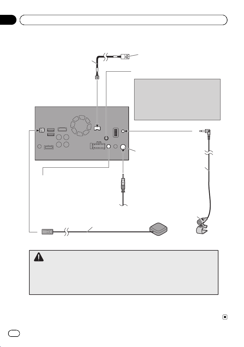
Connection
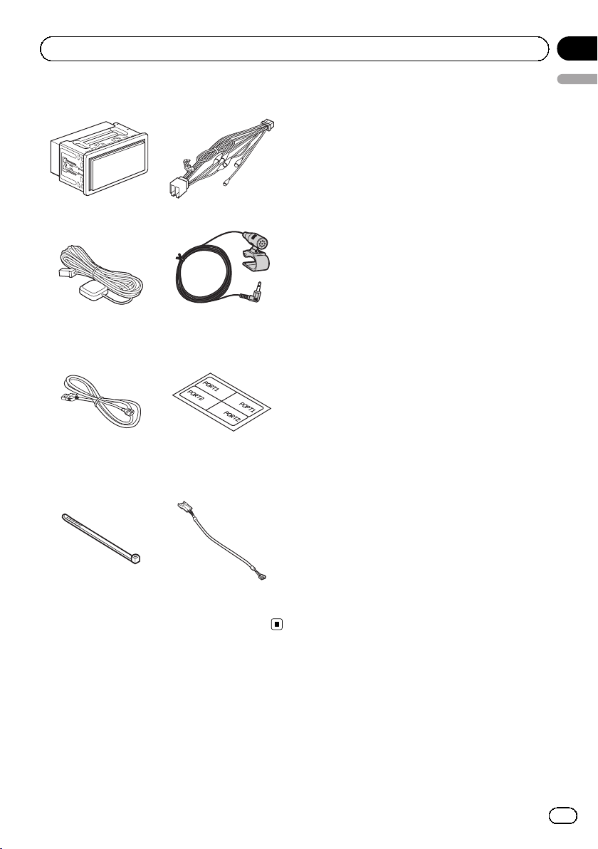
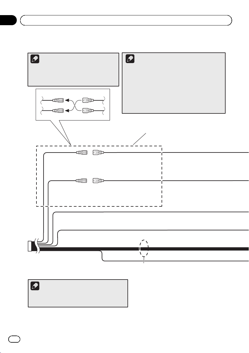
Parts supplied
This product Power cord
GPS aerial Microphone
Section
02
English
USB cable
(2 pcs.)
Lock tie Vehicle Bus conversion
USB cable identification labels
cable
Engb
7
Page 8
Section
02
Connection
Connecting the power cord (1)
Note
Depending on the types of vehicles, the
function of *2 and *4 may be different. In this
case, be sure to connect *1 to *4 and *3 to *2
as shown in the figure.
*2 *1
*4 *3
Yellow (*2)
Back-up
(or accessory)
Red (*4)
Accessory
(or back-up)
Yellow (*1)
To terminal supplied with
power regardless of ignition
switch position.
Red (*3)
To electric terminal controlled by
ignition switch (12 V DC) ON/OFF.
Orange/white
To lighting switch terminal.
Notes
· When a subwoofer (*5) is connected to this product
instead of a rear speaker, change the rear output
setting in the initial setting. (Refer to Operation
Manual.) The subwoofer output of this product is
monaural.
· When using a subwoofer of 70 W (2 Ω), be sure to
connect with violet and violet/black leads of this
product. Do not connect anything with green and
green/black leads.
Connect leads of the
same colour to each other.
8
Black (earth)
To vehicle (metal) body.
ISO connector
Note
In some vehicles, the ISO connector may be divided
into two. In this case, be sure to connect to both
connectors.
Engb
Speaker leads
White: Front left
White/black: Front left
Grey: Front right
Grey/black: Front right
Green: Rear left or Subwoofer (*5)
Green/black: Rear left or Subwoofer (*5)
Violet: Rear right or Subwoofer (*5)
Violet/black: Rear right or Subwoofer (*5)
Page 9
Connection
This product
Fuse (10 A)
Power cord
14 cm
Yellow/black (MUTE)
If you use equipment with a mute function, connect
that equipment to the Audio Mute lead. If not, keep
Power supply
the Audio Mute lead free of any connections.
Note
Audio source will be set to mute or attenuate, while the
following sounds will not be muted or attenuated. For details,
refer to Operation Manual.
— Voice guidance of the navigation
— Incoming ringtone and incoming voice of the mobile phone
that is connected to this product via Bluetooth wireless
technology
Section
02
English
Blue/white (*6)
The pin position of the ISO connector will differ
depending on the types of vehicles. Connect *6
and *7 when Pin 5 is an aerial control type. In
other types of vehicles, never connect *6 and *7.
Blue/white (*7)
To auto-aerial relay control terminal or
aerial booster power control terminal
(max. 300 mA 12 V DC).
Engb
9
Page 10
Section
02
Connection
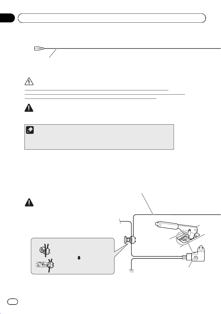
Connecting the power cord (2)
Pink (CAR SPEED SIGNAL INPUT)
This product is connected here to detect the distance the vehicle travels. Always connect the
vehicle’s speed detection circuit. Failure to make this connection will increase errors in the
vehicle’s location display.
WARNING
IMPROPER CONNECTION MAY RESULT IN SERIOUS DAMAGE OR INJURY INCLUDING
ELECTRICAL SHOCK, AND INTERFERENCE WITH THE OPERATION OF THE VEHICLE´S ANTILOCK
BRAKING SYSTEM, AUTOMATIC GEARBOX AND SPEEDOMETER INDICATION.
CAUTION
It is strongly suggested that the speed pulse wire be connected for accuracy of navigation
and better performance.
Note
The position of the speed detection circuit and the position of the handbrake switch vary
depending on the vehicle model. For details, consult your authorised Pioneer dealer or an
installation professional.
Light green (PARKING BRAKE)
Used to detect the ON/OFF status of the handbrake. This lead must be connected to the power supply side
of the handbrake switch.
If this connection is made incorrectly or omitted, certain functions of this product will be unusable.
WARNING
LIGHT GREEN LEAD AT POWER CONNECTOR IS
DESIGNED TO DETECT PARKED STATUS AND MUST
BE CONNECTED TO THE POWER SUPPLY SIDE OF THE
HANDBRAKE SWITCH. IMPROPER CONNECTION OR
USE OF THIS LEAD MAY VIOLATE APPLICABLE LAW
AND MAY RESULT IN SERIOUS INJURY OR DAMAGE.
Connection method
10
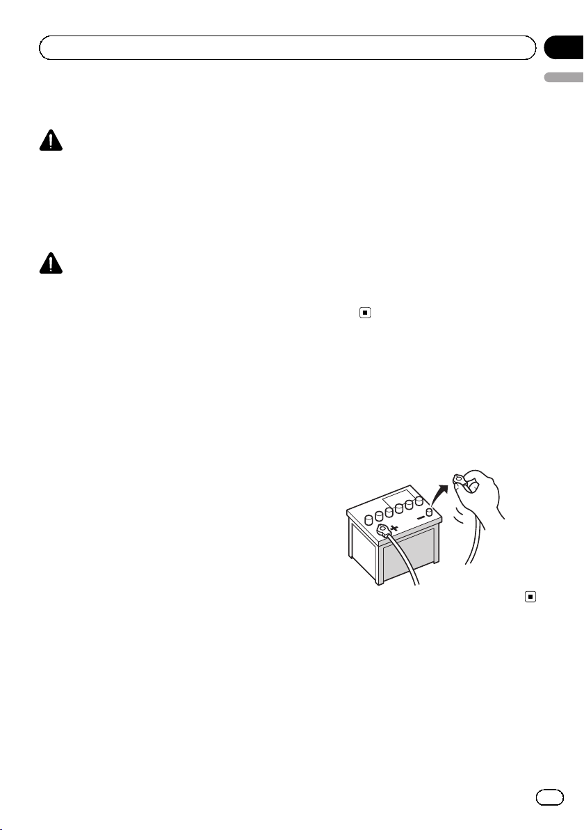
Engb
Clamp the lead of the power supply
side of the handbrake switch.
Clamp firmly with needle-nosed
pliers.
Power supply side
Earth side
Handbrake switch
Page 11
Connection
Section
02
English
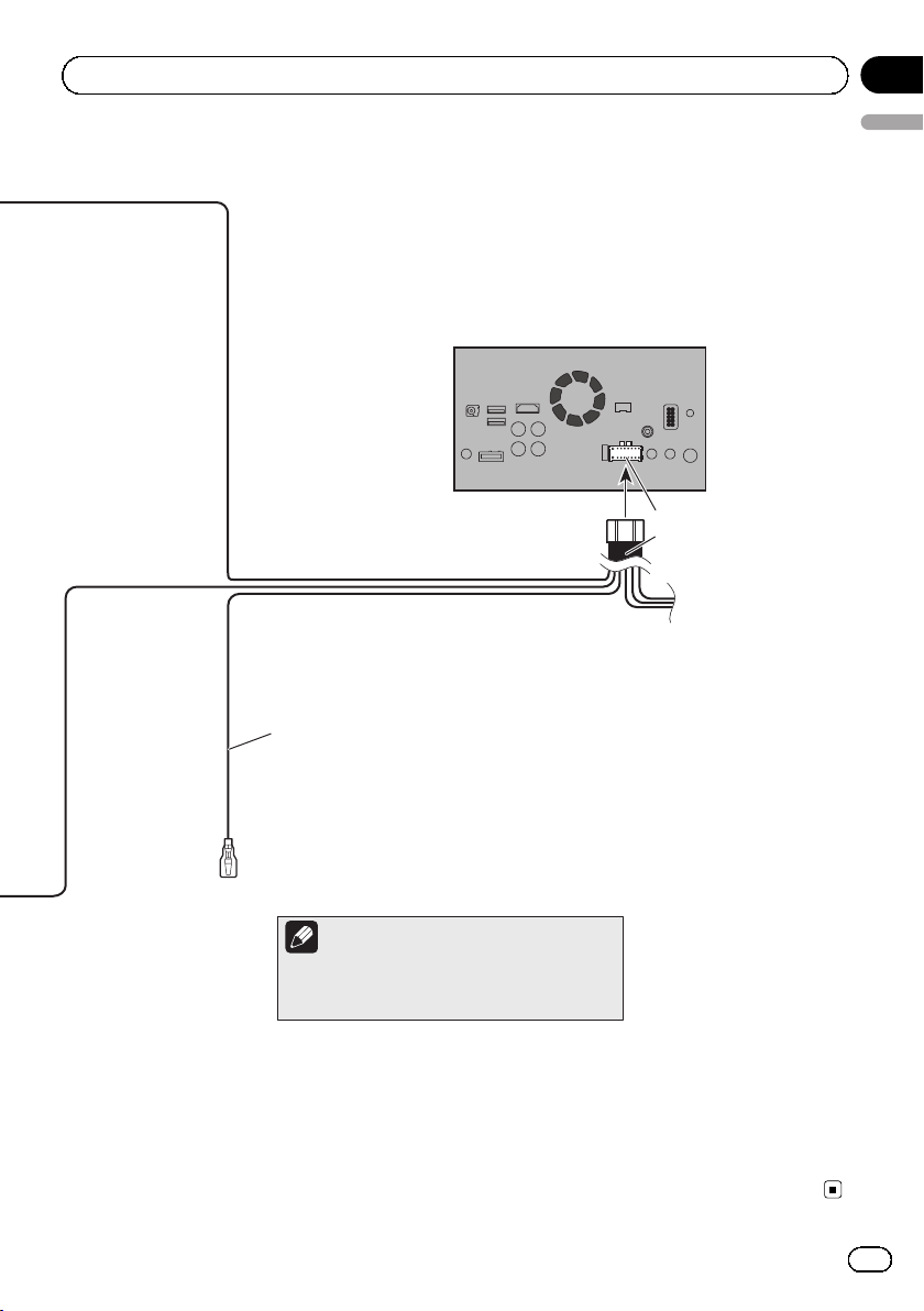
This product
Power supply
Power cord
Violet/white (REVERSE-GEAR SIGNAL INPUT)
This is connected so that this product can detect whether
the vehicle is moving forwards or backwards. Connect the
violet/white lead to the lead whose voltage changes when
the reverse gear is engaged. Unless connected, the sensor
may not detect your vehicle travelling forward/backward
properly, and thus the position of your vehicle detected by
the sensor may be misaligned from the actual position.
Note
When you use a rear view camera, please make
sure to connect this lead. Otherwise you cannot
switch to the rear view camera picture.
Engb
11
Page 12
Section
02
Connection
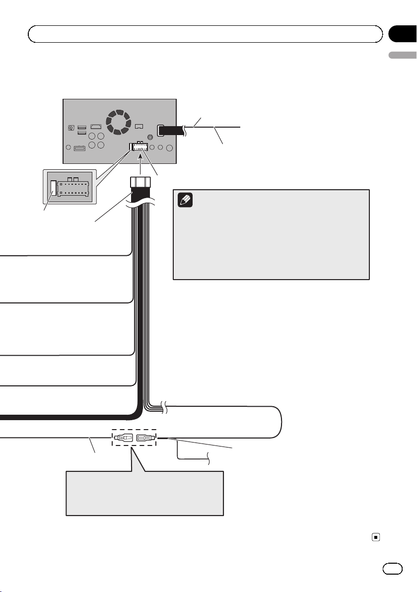
Connecting the system
Vehicle Bus
conversion cable
15.8 cm
This product
Wired remote input
Please refer to the instruction manual for
the Hard-wired remote control adapter
(sold separately).
3.55 m
Vehicle aerial
Vehicle Bus adapter input
Please refer to the instruction manual for
the Vehicle Bus adapter (sold separately).
(AVIC-F60DAB, AVIC-F960DAB)
DAB aerial input
CAUTION:
For improved Digital Radio reception, make sure
a Digital Radio antenna with phantom power
input (active type) is used. Pioneer recommends
using AN-DAB1 (sold separately). Current
consumption of Digital Radio antenna should
be 100 mA or less.
Aerial jack
4 m
Microphone
GPS aerial
12
WARNING
· To avoid the risk of accident and the potential violation of applicable laws, this product should
never be used while the vehicle is being driven except for navigation purposes. And, also rear
displays should not be in a location where it is a visible distraction to the driver.
· In some countries, the viewing of images on a display inside a vehicle even by persons other than
the driver may be illegal. Where such regulations apply they must be obeyed and this product’s
video source should not be used.
Engb
Page 13
Connection
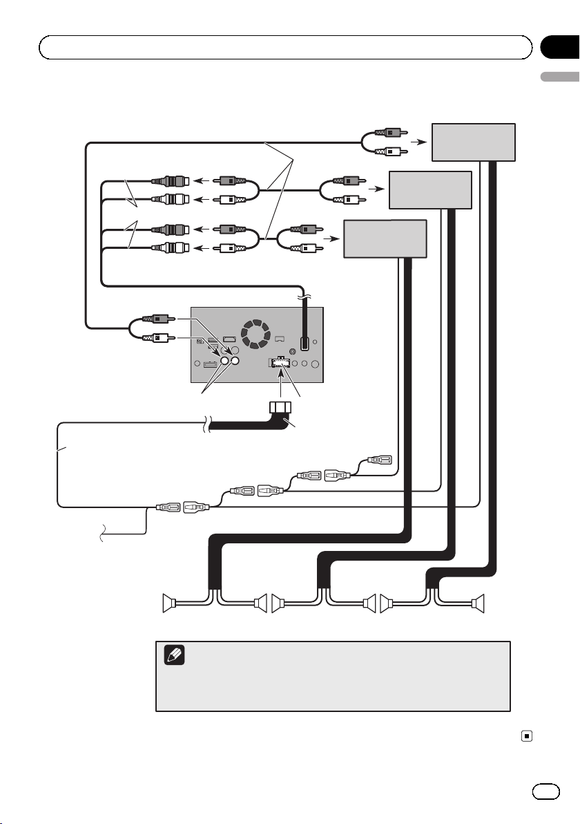
Connecting to separately sold power amp
RCA
Rear outputs
(REAR OUTPUT)
15 cm
Front outputs
(FRONT OUTPUT)
This product
cables
(sold separately)
Power amp
(sold separately)
Power amp
(sold separately)
Power amp
(sold separately)
Section
02
English
White, Red (SWL, SWR)
Blue/white
To system control terminal of the power amp
(max. 300 mA 12 V DC).
If your vehicle is
equipped with an
auto-aerial, connect
this lead to a power
amp.
Front speaker
Notes
· You can change the RCA output of the subwoofer depending on your subwoofer
system. (Refer to Operation Manual.)
· The subwoofer output of this product is monaural.
Power supply
Power cord
System remote control
Rear speaker
Subwoofer
Engb
13
Page 14
Section
02
Connection
Attaching identification
labels to USB cables
Attach identification labels to USB cables before installing this product in a vehicle.
1 Connect USB cables to the USB port 1
and 2 on the rear of this product.
2 Attach the identification labels corresponding to each port to the USB cables as
illustrated below.
Attach the “PORT 1” label to the USB cable
connected to the USB port 1.
Attach the “PORT 2” label to the USB cable
connected to the USB port 2.
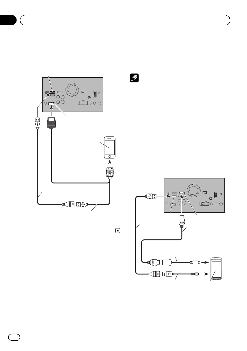
Connecting an iPhone with
Lightning connector
Notes
! For details on how to connect an external de-
vice using a separately sold cable, refer to the
manual for the cable.
! For details concerning the connection, opera-
tions and compatibility of iPhone, refer to Operation Manual.
Connecting via the USB port
The USB interface cable for iPod / iPhone (CDIU52) (sold separately) is required for the connection.
USB port 1
USB port 2
This product
14
iPhone with
Lightning connector
USB cable
1.5 m
USB interface cable for iPod / iPhone
(CD-IU52) (sold separately)
Engb
Page 15
Connection
Connecting via the HDMI port
The following cables are required for the connection.
! HDMI interface cable for iPod / iPhone
(CD-IH202) (sold separately)
! USB interface cable for iPod / iPhone (CD-
IU52) (sold separately)
! Lightning Digital AV Adapter (Apple Inc.
products) (sold separately)
USB port 1
This product
Section
02
English
Connecting an iPhone with
30-pin connector
Notes
! For details on how to connect an external de-
vice using a separately sold cable, refer to the
manual for the cable.
! For details concerning the connection, opera-
tions and compatibility of iPhone, refer to Operation Manual.
Connecting via the AUX input
The USB interface cable for iPod / iPhone (CDIU201V) (sold separately) is required for the
connection.
HDMI port
USB cable
1.5 m
High Speed HDMI
(Type A - A)
(supplied with CD-IH202)
Lightning Digital AV Adapter
(Apple Inc. products)
(sold separately)
USB interface cable for iPod / iPhone
(CD-IU52) (sold separately)
iPhone with
Lightning connector
®
Cable
Note
! When you connect the High Speed HDMI
Cable, use the lock tie to fix it securely.
= For details, refer to Securing the High
Speed HDMI
®
Cable on page 18.
USB port 1
USB port 2
USB cable
1.5 m
USB interface cable for iPod / iPhone
(CD-IU201V) (sold separately)
This product
AUX input
iPhone with
30-pin connector
Note
Connect the USB cable to USB port 1 when using
“aha” as the source.
®
Engb
15
Page 16
Section
02
Connection
Connecting via the RGB input
The USB interface cable for iPod / iPhone (CDIU201S) (sold separately) is required for the
connection.
USB port 1
USB cable
1.5 m
This product
RGB input
iPhone with
30-pin connector
Connecting the Android
™
device
App Connectivity Kit (CD-AH200) (sold separately) is required for the connection.
Notes
! For details on how to connect an external de-
vice using a separately sold cable, refer to the
manual for the cable.
! For details concerning the connection and op-
erations of Android device, refer to Operation
Manual.
! When you connect the High Speed HDMI
Cable, use the lock tie to fix it securely.
= For details, refer to Securing the High
Speed HDMI
®
Cable on page 18.
Connecting an Android device
with an HDMI port
This product
®
16
USB interface cable for iPod / iPhone
(CD-IU201S) (sold separately)
Engb
USB port 2
USB cable
1.5 m
Adapter cable
(HDMI Type A - D)
(supplied with CD-AH200)
USB - micro USB cable
(Type USB A - micro USB B)
(supplied with CD-AH200)
HDMI port
High Speed HDMI®
Cable (Type A - A)
(supplied with
CD-AH200)
Android device
Page 17
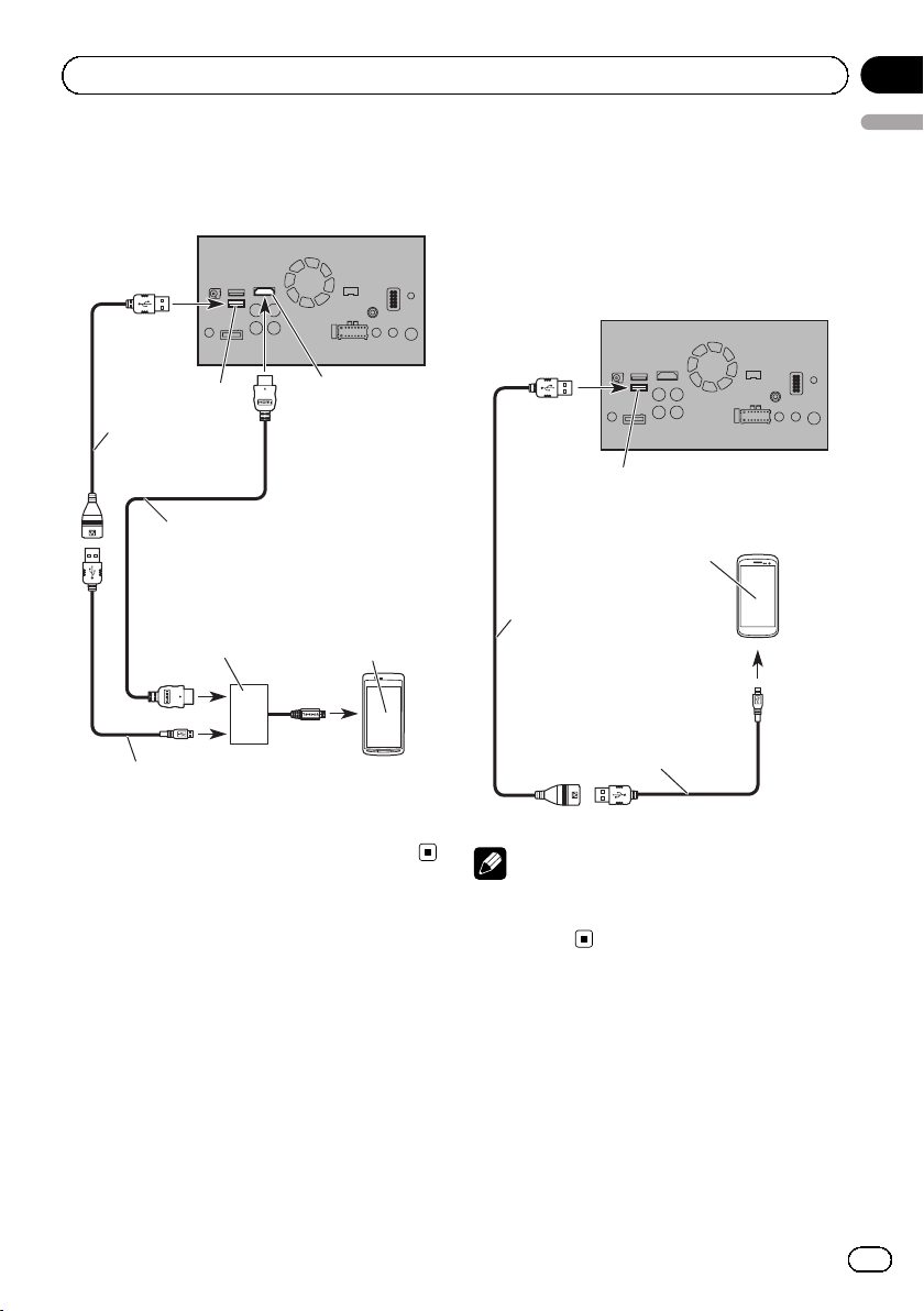
Connection
Connecting an Android device
with an MHL port
This product
Connecting the MirrorLink
device
The USB interface cable for use with Mirror-
™
Link
devices (CD-MU200) (sold separately) is
required for the connection.
This product
™
Section
02
English
USB port 2
USB cable
1.5 m
High Speed HDMI® Cable
(Type A - A)
(supplied with CD-AH200)
MHL adapter
(supplied with
CD-AH200)
USB - micro USB cable
(Type USB A - micro USB B)
(supplied with CD-AH200)
HDMI port
Android device
USB port 2
MirrorLink device
USB cable
1.5 m
USB - micro USB cable
(Type USB A - micro USB B)
(supplied with CD-MU200)
Note
For details on how to connect an external device
using a separately sold cable, refer to the manual
for the cable.
Engb
17
Page 18
Section
02
Connection
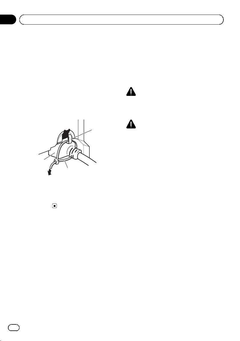
Securing the High Speed
®
HDMI
Be sure to fix the High Speed HDMI®Cable
with the lock tie, when you connect the external device with the High Speed HDMI
1 Insert the High Speed HDMI
the HDMI port.
2 Wrap the lock tie around the hook
above the HDMI port and the High Speed
HDMI
the High Speed HDMI
1 Hook
2 Lock tie
3 High Speed HDMI
p Do not tighten up the lock tie more than
Cable
®
®
Cable into
®
Cable, and then tighten it to secure
3
necessary.
®
Cable.
2
®
Cable
1
Cable.
Connecting a rear view camera
When this product is used with a rear view
camera, it is possible to automatically switch
from the video to rear view image when the
gearstick is moved to REVERSE (R). Camera
View mode also allows you to check what is
behind you while driving.
WARNING
USE INPUT ONLY FOR REVERSE OR MIRROR
IMAGE REAR VIEW CAMERA. OTHER USE MAY
RESULT IN INJURY OR DAMAGE.
CAUTION
! The screen image may appear reversed.
! The rear view camera is used as an aid to
keep an eye on trailers, or backing into a tight
parking spot. Do not use this function for entertainment purposes.
! Objects in rear view may appear closer or
more distant than in reality.
! Please note that the image area shown by the
rear view camera may differ slightly when fullscreen images are displayed when backing
and when checking the rear of the vehicle
while moving forward.
18
Engb
Page 19
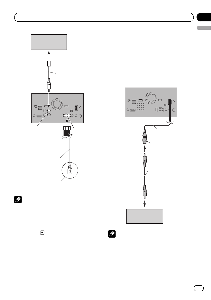
Connection
Rear view camera
(ND-BC6)
(sold separately)
To video output
Section
02
English
Connecting the external
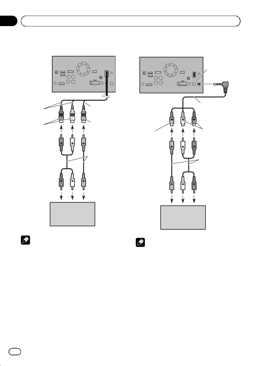
video component
Using AV input
You can connect an external video component
or external camera to this product.
RCA cable
(supplied with ND-BC6)
This product
Brown (BC IN)
Violet/white
(REVERSE-GEAR SIGNAL
INPUT)
For more details about the wiring, refer to Connecting
the power cord (2) on page 10.
Power supply
Power cord
Notes
! This mode is available when the rear view
camera setting is set to “On”. (For details,
refer to Operation Manual.)
! Connect this product to the rear view camera
only. Do not connect to any other
equipment.
Connecting an external camera
This product
15 cm
Yel low
(VIDEO INPUT
OR CAMERA
INPUT)
RCA cable
(sold separately)
To video output
External camera
(sold separately)
Note
This mode is available when the setting of AV
input is set to “Camera”. (For details, refer to Operation Manual.)
Engb
19
Page 20
Section
02
Connection
Connecting the video component
This product
23 cm
Red, white
(AUDIO INPUT)
External video
component
(sold separately)
15 cm
Yellow
(VIDEO INPUT
OR CAMERA
INPUT)
RCA cables
(sold separately)
To video outputTo audio outputs
Using an AUX input
This product
AUX input
Mini-jack AV cable
(CD-RM10)
(sold separately)
Yel low
To video output To audio outputs
External video
component
(sold separately)
Red, white
RCA cables
(sold separately)
Note
This mode is available when the setting of AV
input is set to “Source”. (For details, refer to Operation Manual.)
20
Engb
Notes
! This mode is available when the setting of
AUX input is set to “On”. (For details, refer to
Operation Manual.)
! When connecting an external video compo-
nent using a mini-jack AV cable, use a separately sold AUX extension cable as necessary.
Page 21
Connection
CAUTION
Be sure to use a mini-jack AV cable (CD-RM10)
(sold separately) for wiring. If you use other
cables, the wiring position might differ resulting
in disturbed images and sounds.
OK
L : Left audio (White)
L
GVR
R : Right audio (Red)
L
V : Video (Yellow)
GRV
G : Earth
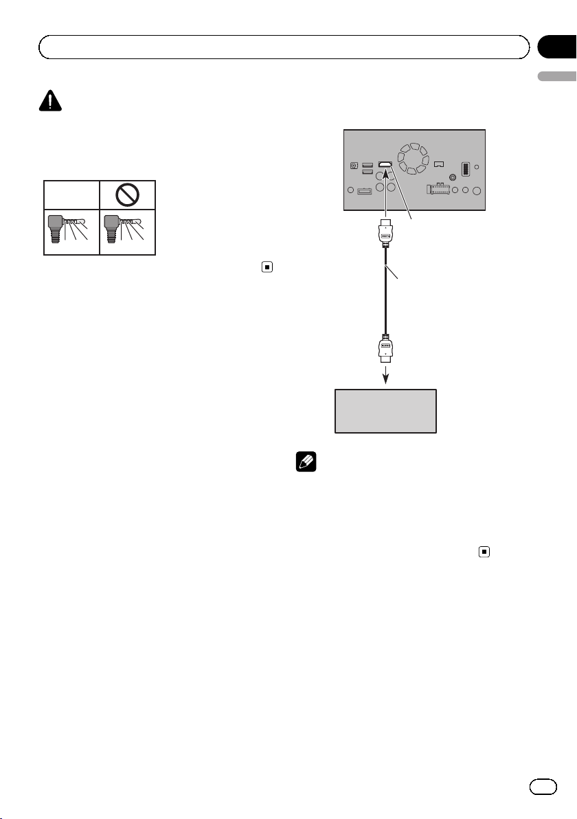
Connecting an HDMI device
This product
HDMI port
®
High Speed HDMI
Cable
(sold separately)
Section
02
English
HDMI device
(sold separat
ely)
Notes
! For details concerning the operations of HDMI
device, refer to Operation Manual.
! When you connect the High Speed HDMI
®
Cable, use the lock tie to fix it securely.
= For details, refer to Securing the High
Speed HDMI
®
Cable on page 18.
Engb
21
Page 22
Section
02
Connection
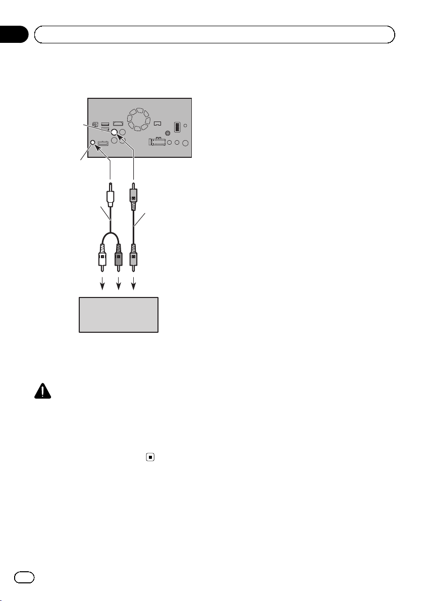
Connecting the rear display
Yellow (V OUT)
Rear audio
output
Mini pin plug cable
(sold separately)
RCA cable
(sold separately)
This product
To audio inputs
Rear display with
RCA input jacks
(sold separately)
To video input
When using a rear display
connected to rear video output
WARNING
NEVER install the rear display in a location
that enables the driver to watch the video
source while driving.
This product’s rear video output is for connection
of a display to enable passengers in the rear
seats to watch the video source.
22
Engb
Page 23
Installation
Section
03
Precautions before
installation
CAUTION
! Never install this product in places where,
or in a manner that:
— Could injure the driver or passengers if
the vehicle stops suddenly.
— May interfere with the driver’s opera-
tion of the vehicle, such as on the floor
in front of the driver’s seat, or close to
the steering wheel or gearstick.
! Make sure there is nothing behind the
dashboard or panelling when drilling
holes in them. Be careful not to damage
fuel lines, brake lines, electronic components, communication wires or power
cables.
! When using screws, do not allow them to
come into contact with any electrical lead.
Vibration may damage wires or insulation,
leading to a short circuit or other damage
to the vehicle.
! To ensure proper installation, be sure to
use the supplied parts in the manner specified. If any parts are not supplied with
this product, use compatible parts in the
manner specified after you have the parts’
compatibility checked by your dealer. If
parts other than supplied or compatible
ones are used, they may damage internal
parts of this product or they may work
loose and the product may become detached.
! It is extremely dangerous to allow cables
to become wound around the steering column or gearstick. Be sure to install this
product, its cables, and wiring away in
such so that they will not obstruct or hinder driving.
! Make sure that leads cannot get caught in
a door or the sliding mechanism of a seat,
resulting in a short circuit.
! Please confirm the proper function of
your vehicle’s other equipment after installation of this product.
! Do not install this product where it may (i)
English
obstruct the driver’s vision, (ii) impair the
performance of any of the vehicle’s operating systems or safety features, including airbags, hazard lamp buttons or (iii)
impair the driver’s ability to safely operate the vehicle.
! Install this product between the driver’s
seat and front passenger seat so that it
will not be hit by the driver or passenger if
the vehicle stops quickly.
! Never install this product in front of or
next to the place in the dashboard, door,
or pillar from which one of your vehicle’s
airbags would deploy. Please refer to your
vehicle’s owner’s manual for reference to
the deployment area of the frontal airbags.
! Failure to follow all of these precautions
may result in serious injury or death.
To avoid electromagnetic
interference
In order to prevent interference, set the following items as far as possible from this product,
other cables or leads:
! FM, MW/LW aerial and its lead
! DAB aerial and its lead (for AVIC-F60DAB
and AVIC-F960DAB)
! GPS aerial and its lead
In addition, you should lay or route each aerial
lead as far as possible from other aerial leads.
Do not bind, lay or route them together, or
cross them. Electromagnetic noise will increase the potential for errors in the vehicle’s
location display.
Before installing
! Consult with your nearest dealer if installa-
tion requires drilling holes or other modifi-
cations of the vehicle.
Engb
23
Page 24
Section
03
Installation
! Before making a final installation of this
product, temporarily connect the wiring to
confirm that the connections are correct
and the system works properly.
For AVIC-F60DAB users
Do not install this product in a position where
the opening of the LCD panel is obstructed by
any obstacles, such as the gearstick. Before
installing this product, be sure to leave sufficient space so that the LCD panel does not obstruct the gearstick when it is fully opened.
This may cause interference with the gearstick, or a malfunction of the mechanism of
this product.
Installing this product
Installation notes
! Do not install this product in places subject
to high temperatures or humidity, such as:
— Places close to a heater, vent or air con-
ditioner.
— Places exposed to direct sunlight, such
as on top of the dashboard.
— Places that may be exposed to rain,
such as close to the door or on the vehicle’s floor.
! Install this product in an area strong en-
ough to bear its weight. Choose a position
where this product can be firmly installed,
and install it securely. If this product is not
securely installed, the current location of
the vehicle cannot be displayed correctly.
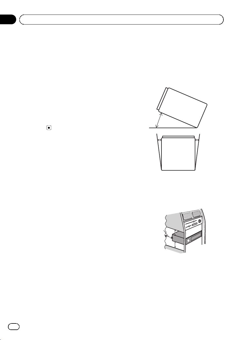
! Install this product horizontally on a sur-
face within 0 to 30 degrees tolerance (within 5 degrees to the left or right). Improper
installation of the unit with the surface
tilted more than these tolerances increases
the potential for errors in the vehicle’s location display, and might otherwise cause reduced display performance.
30°
5° 5°
! When installing, to ensure proper heat dis-
persal when using this unit, make sure you
leave ample space behind the rear panel
and wrap any loose cables so they are not
blocking the vents.
Leave ample
space
5 cm
5 cm
24
Engb
Page 25
1
Installation
Section
03
! The cords must not cover the area shown
in the figure below. This is necessary to
allow the amps and navigation mechanism
to dissipate heat.
Do not cover this area.
! The semiconductor laser will be damaged
if it overheats, so don’t install this product
anywhere hot — for instance, near a heater
outlet.
Parts supplied
Parts marked (*) are pre-installed.
English
Before installing this product
1 Remove the trim ring.
Extend top and bottom of the trim ring outwards to remove the trim ring.
1 Trim ring
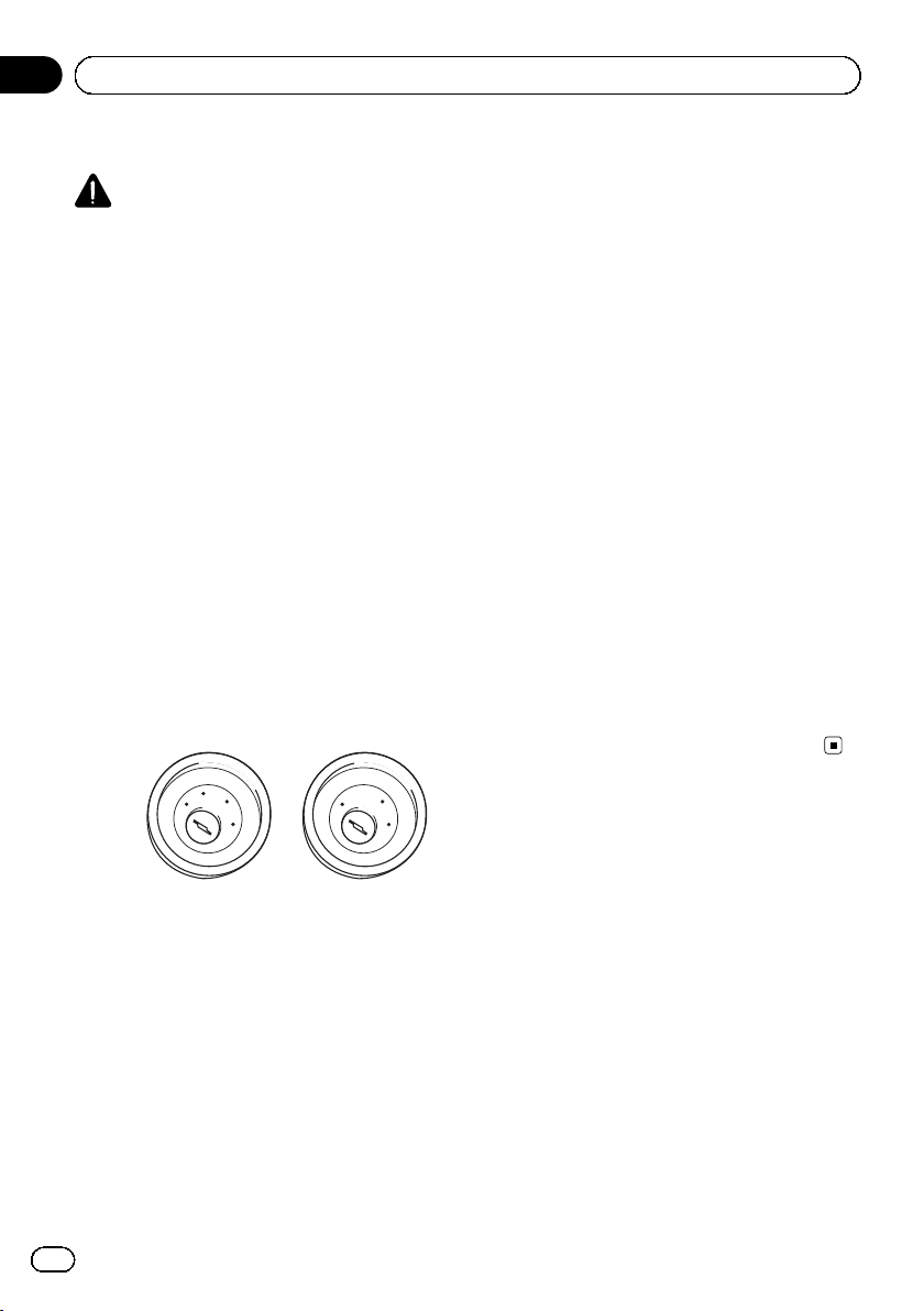
2 Insert the supplied extraction keys into
both sides of the unit until they click into
place.
3 Pull the unit out of the holder.
1
This product Holder*
Truss head screw
(5 mm × 8 mm)
(6 pcs.)
Trim ring* Extraction Key
Flush surface screw
(5 mm × 9 mm)
(6 pcs.)
(2 pcs.)
1 Extraction key
Installation with the holder
1 Install the holder into the dashboard.
2 Secure the mounting sleeve by using a
screwdriver to bend the metal tabs (90°)
into place.
1
2
Engb
25
Page 26
2
Section
03
Installation
1 Dashboard
2 Holder
3 Install this product into the holder.
1
1 Dashboard
4 Attach the trim ring.
Installation using the screw
holes on the side of this product
% Fastening this product to the factory
radio-mounting bracket.
Position this product so that its screw holes
are aligned with the screw holes of the bracket, and tighten the screws at three locations
on each side.
Use either the truss head screws (5 mm ×
8 mm) or flush surface screws (5 mm ×
9 mm), depending on the shape of the bracket’s screw holes.
If the pawl interferes with installation,
you may bend it down out of the way.
1
26
1
2
3
1 Trim ring
2 Groove
Attach the trim ring with the side with a
groove facing downward.
1 Factory radio-mounting bracket
2 Dashboard or console
3 Truss head screw or flush surface screw
Be sure to use the screws supplied with
this product.
Engb
Page 27
Installation
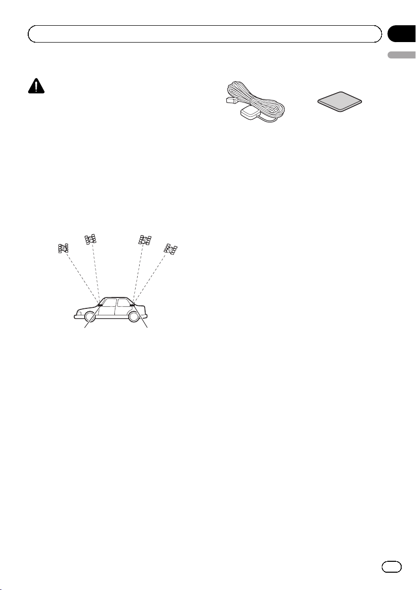
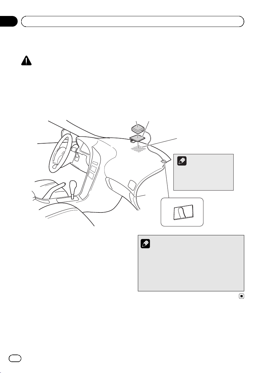
Installing the GPS aerial
CAUTION
Do not cut the GPS aerial lead to shorten it
or use an extension to make it longer. Altering the aerial cable could result in a short circuit or malfunction and permanent damage
to this product.
Installation notes
! The aerial should be installed on a level sur-
face where radio waves will be blocked as
little as possible. Radio waves cannot be received by the aerial if reception from the satellite is blocked.
Section
03
English
Parts supplied
GPS aerial Metal sheet
12
1 Dashboard
2 Rear shelf
! When installing the GPS aerial inside the
vehicle, be sure to use the metal sheet provided with your system. If this is not used,
the reception sensitivity will be poor.
! Do not cut the accessory metal sheet. This
would reduce the sensitivity of the GPS aerial.
! Take care not to pull the aerial lead when
removing the GPS aerial. The magnet attached to the aerial is very powerful, and
the lead may become detached.
! Do not paint the GPS aerial, as this may af-
fect its performance.
Engb
27
Page 28
3
Section
03
Installation
When installing the aerial inside the vehicle (on the dashboard or
rear shelf)
WARNING
Do not install the GPS aerial over any sensors or vents on the dashboard of the vehicle,
as doing so may interfere with the proper
functioning of such sensors or vents and may
compromise the ability of the metal sheet
under the GPS aerial to properly and securely affix to the dashboard.
12
Make sure the surface is
free of moisture, dust,
grime, oil, etc., before
affixing the metal sheet.
Note
The metal sheet contains a
strong adhesive which may
leave a mark on the surface
if it is removed.
1 GPS aerial
2 Metal sheet
Peel off the protective sheet on the rear.
3 Clamps
Use separately sold clamps to secure the lead
where necessary inside the vehicle.
Affix the metal sheet on the surface as level as
possible where the GPS aerial faces the window. Place the GPS aerial on the metal sheet.
(The GPS aerial is fastened with its magnet.)
28
Engb
Notes
! When attaching the metal sheet, do not cut
it into small pieces.
! Some models use window glass that does
not allow signals from GPS satellites to
pass through. On such models, install the
GPS aerial on the outside of the vehicle.
Page 29
Installation
Section
03
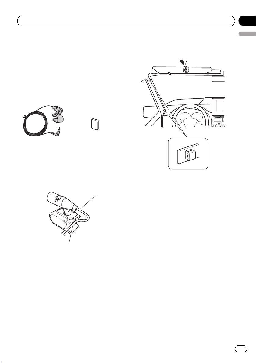
Installing the microphone
! Install the microphone in a place where its
direction and distance from the driver
make it easiest to pick up the driver’s voice.
! Be sure to turn off (ACC OFF) the product
before connecting the microphone.
Parts supplied
Microphone Double-sided tape
Mounting on the sun visor
1 Fit the microphone lead into the
groove.
1
2 Attach the microphone clip to the sun
English
visor.
1
2
1 Microphone clip
2 Clamps
Use separately sold clamps to secure the
lead where necessary inside the vehicle.
Install the microphone on the sun visor when
it is in the up position. It cannot recognise the
driver’s voice if the sun visor is in the down position.
1 Microphone lead
2 Groove
2
Engb
29
Page 30
Section
03
Installation
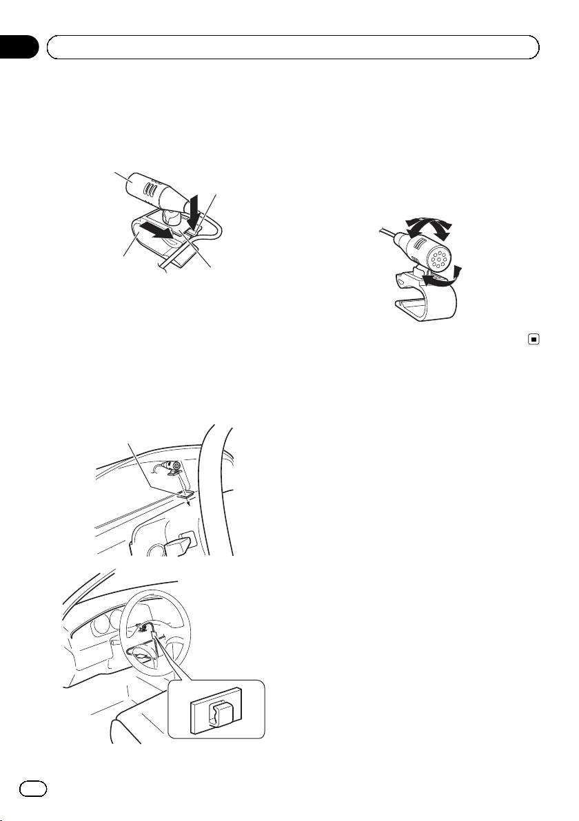
Installation on the steering column
1 Detach the microphone base from the
microphone clip by sliding the microphone
base while pressing the tab.
1
2
4
3
1 Microphone
2 Tab
3 Microphone base
4 Microphone clip
2 Mount the microphone on the steering
column.
Install the microphone on the steering column, keeping it away from the steering wheel.
1
1 Double-sided tape
2 Clamps
Use separately sold clamps to secure the
lead where necessary inside the vehicle.
Adjusting the microphone angle
The microphone angle can be adjusted.
30
2
Engb
Page 31

After installation
Section
04
After installing this product
1 Reconnect the negative (–) terminal of
the vehicle’s battery.
First, double-check that all connections are
correct and that this product is installed correctly. Reassemble all vehicle components
that you previously removed. Then reconnect
the negative (–) cable to the negative (–) terminal of the battery.
2 Start the engine.
3 Press the RESET button.
Press the RESET button on this product with a
pointed object such as the tip of a pen.
F60DAB
F960DAB F960BT
5 Drive down an unobstructed road until
English
the GPS starts receiving the signal normally.
Note
After installing this product, be sure to check at a
safe place that the vehicle is performing normally.
p Some of the settings and recorded contents
will not be reset.
4 Change the settings as desired.
= For details concerning operations, refer to
Operation Manual.
Engb
31
Page 32

Sommaire
Précautions
Votre nouveau produit et ce manuel 33
Importantes mesures de sécurité 33
Connexion
Précautions à prendre avant de brancher le
système 35
Avant d’installer ce produit 35
Pour éviter toute détérioration 36
– Remarque concernant le fil bleu/
blanc 36
Pièces fournies 37
Branchement du cordon d’alimentation
(1) 38
Branchement du cordon d’alimentation
(2) 40
Branchement du système 42
Connexion à un amplificateur de puissance
vendu séparément 43
Apposition d’étiquettes d’identification aux
câbles USB 44
Connexion d’un iPhone avec connecteur
Lightning 44
– Connexion via le port USB 44
– Connexion via le port HDMI 45
Connexion d’un iPhone avec connecteur à
30broches 45
– Connexion via l’entrée AUX 45
– Connexion via l’entrée RGB 46
Connexion d’un périphérique Android™ 46
– Connexion d’un périphérique Android
via un port HDMI 46
– Connexion d’un périphérique Android
via un port MHL 47
Connexion d’un périphérique
MirrorLink™ 47
Fixation du câble HDMI
Connexion d’une caméra de rétrovisée 48
Connexion d’un élément vidéo externe 49
R
haute vitesse 48
– Utilisation de l’entrée AV 49
– Utilisation d’une entrée AUX 50
Connexion d’un périphérique HDMI 51
Connexion de l’afficheur arrière 52
– Utilisation d’un écran arrière raccordé
à la sortie vidéo arrière 52
Installation
Précautions à prendre avant
l’installation 53
Pour éviter les parasites
électromagnétiques 53
Avant de procéder à l’installation 54
– Pour les utilisateurs de AVIC-
F60DAB 54
Installation de ce produit 54
– Remarques sur l’installation 54
– Pièces fournies 55
– Avant d’installer ce produit 56
– Installation avec le support 56
– Installation en utilisant les trous de vis
sur les côtés de ce produit 57
Installation de l’antenne GPS 58
– Remarques sur l’installation 58
– Pièces fournies 58
– Installation de l’antenne dans le
véhicule (sur le tableau de bord ou la
lunette arrière) 59
Installation du microphone 60
– Pièces fournies 60
– Installation sur le pare-soleil 60
– Installation sur la colonne de
direction 61
– Réglage de l’angle du microphone 61
Après l’installation
Après avoir installé ce produit 62
32
Fr
Page 33

Précautions
Section
01
Votre nouveau produit et
ce manuel
! La fonction de navigation de ce produit (et
la caméra de rétrovisée en option le cas
échéant) est uniquement destinée à vous
assister lors de la conduite de votre véhicule. Elle n’autorise en aucun cas un relâchement de votre attention, de votre
jugement et de votre vigilance pendant la
conduite.
! N’utilisez jamais ce produit pour joindre
des hôpitaux, postes de police ou établissements similaires en cas d’urgence. Appelez
le numéro d’urgence approprié.
! N’utilisez pas ce produit, n’importe quelle
application ou la caméra de rétrovisée en
option (le cas échéant) si celui-ci risque
d’une façon ou d’une autre de détourner
votre attention. Observez toujours les règles de sécurité et respectez toujours les
réglementations de la circulation routière
en vigueur. Si vous éprouvez des difficultés
à utiliser ce produit ou à lire l’écran, garez
votre véhicule en lieu sûr et serrez le frein à
main avant d’effectuer les réglages nécessaires.
! Ce manuel explique comment installer ce
produit dans votre véhicule. Le fonctionnement de ce produit est expliqué dans les
manuels séparés.
! N’installez pas ce produit dans un endroit
où il risque (i) d’entraver la visibilité du
conducteur, (ii) d’altérer le fonctionnement
de certains systèmes de commande des
dispositifs de sécurité du véhicule, y
compris les airbags ou les touches de feux
de détresse, ou (iii) d’empêcher le conducteur de conduire le véhicule en toute sécurité. Dans certains cas, il peut ne pas être
possible d’installer ce produit en raison du
type de véhicule ou de la forme de l’intérieur du véhicule.
Importantes mesures de
sécurité
AVERTISSEMENT
Pioneer vous recommande de ne pas installer ce produit vous-même. Ce produit doit
être exclusivement installé par un professionnel. Nous recommandons que seul le
personnel d’entretien Pioneer agréé, qui dispose d’une formation et d’une expérience
spéciales dans l’électronique mobile, configure et installe ce produit. N’INTERVENEZ
JAMAIS SUR CE PRODUIT VOUS-MÊME.
L’installation ou l’entretien de ce produit et
de ses câbles de connexion peut vous exposer à un risque de choc électrique ou à d’autres dangers, et peut entraîner des
dommages du produit non couverts par la garantie.
! Lisez attentivement le contenu de ce ma-
nuel avant d’installer ce produit.
! Conservez ce manuel à portée de main
pour vous y reporter ultérieurement.
! Tenez compte de tous les avertissements
formulés dans ce manuel et respectez soigneusement les consignes.
! Dans certaines circonstances, ce produit
peut ne pas afficher la position correcte de
votre véhicule, la distance des objets affichés à l’écran et les directions. Le système
présente en outre certaines restrictions, notamment l’incapacité d’identifier les rues à
sens unique, des limitations temporaires
du trafic et des zones potentiellement dangereuses. Adoptez les mesures nécessaires
en fonction des conditions de conduite
réelles.
! Comme tout autre accessoire intérieur de
votre véhicule, ce produit ne doit pas vous
distraire de la bonne conduite de votre véhicule au risque d’entraîner des blessures
graves voire mortelles. Si vous éprouvez
des difficultés à utiliser le système ou à lire
l’afficheur, procédez aux réglages lorsque
le véhicule à l’arrêt.
Français
33
Fr
Page 34

Section
01
Précautions
! Veillez à toujours porter votre ceinture de
sécurité sur la route. En cas d’accident, le
port de la ceinture peut réduire considérablement la gravité des blessures.
! Certaines lois nationales ou gouvernemen-
tales peuvent interdire ou restreindre l’emplacement et l’utilisation de ce produit
dans votre véhicule. Veuillez vous conformer à toutes les lois et réglementations en
vigueur concernant l’utilisation, l’installation et le fonctionnement de ce produit.
34
Fr
Page 35

Connexion
Section
02
Précautions à prendre avant
de brancher le système
AVERTISSEMENT
N’essayez pas de modifier ou désactiver le
système de verrouillage du frein à main, lequel est installé pour votre protection. La modification ou la désactivation du système de
verrouillage du frein à main peut entraîner
des blessures graves, voire mortelles.
ATTENTION
! Si vous décidez de réaliser l’installation
vous-même, et possédez une expérience
spéciale en installation d’électronique automobile, veuillez suivre attentivement
toutes les étapes du manuel d’installation.
! Attachez tous les fils avec des colliers ou
des serre-câbles. Ne laissez aucun fil à nu.
! Ne raccordez pas directement le fil jaune
conducteur de ce produit à la batterie du
véhicule. Si ce fil conducteur est directement raccordé à la batterie, les vibrations
du moteur peuvent finir par user les câbles au niveau de la jonction avec l’habitacle et provoquer un défaut d’isolation. Si
l’isolation du fil conducteur jaune se déchire sous l’effet du contact avec des pièces métalliques, il peut en résulter un
court-circuit extrêmement dangereux.
! Il est extrêmement dangereux de laisser
les câbles s’enrouler autour de la colonne
de direction ou du levier de vitesse. Assurez-vous d’installer ce produit, ses câbles
et les fils de telle façon qu’ils n’obstruent
ni ne gênent la conduite.
! Veillez à ce que la trajectoire des câbles et
des fils n’interfère pas avec les pièces en
mouvement du véhicule. Fixez les câbles
de manière à les empêcher d’être happés
par, notamment, le volant, le levier de vitesse, le frein à main, les glissières de
siège, les portes, ou tout autre élément de
commande du véhicule.
! La trajectoire des fils ne doit pas être ex-
posée à des températures élevées. Si l’isolation chauffe, les fils risquent d’être
endommagés, ce qui peut entraîner un
court-circuit ou un dysfonctionnement, et
endommager de manière irrémédiable le
produit.
! Ne coupez pas le câble de l’antenne GPS
et n’utilisez pas de rallonge. Une telle modification pourrait provoquer un court-circuit ou un dysfonctionnement.
! Ne raccourcissez aucun fil conducteur.
Vous risqueriez autrement de provoquer
un dysfonctionnement du circuit de protection (porte-fusibles, résistance de fusible ou filtre, etc.).
! N’utilisez jamais le cordon d’alimentation
de ce produit pour raccorder d’autres appareils électriques. La capacité du cordon
serait dépassée, ce qui provoquerait une
surchauffe.
Avant d’installer ce produit
! Utilisez cet appareil uniquement avec une
batterie de 12 V, avec pôle négatif à la
masse. Sinon, cela pourrait entraîner un incendie ou un mauvais fonctionnement.
! Afin d’éviter tout risque de court-circuit, dé-
branchez le câble de la borne négative (–)
de la batterie avant de commencer la pose.
Français
35
Fr
Page 36

Section
02
Connexion
Pour éviter toute
détérioration
AVERTISSEMENT
! Utilisez des haut-parleurs de plus de 50 W
(valeur de sortie) et avec une impédance
comprise entre 4 W et 8 W.N’utilisez pas de
haut-parleurs 1 W à3W avec cet appareil.
! Le câble noir est mis à la masse. Veuillez
mettre à la masse ce câble séparément de
la masse des produits haute tension tels
que les amplificateurs de puissance. Ne
reliez pas plus d’un produit à la masse
d’un autre produit. Par exemple, vous
devez relier à la masse chaque unité d’amplificateur séparément de la masse de ce
produit. Le fait de raccorder les masses
ensemble risque de provoquer un incendie et/ou d’endommager les produits, si
les fils de masse se déconnectent.
! Lors du remplacement du fusible, veillez à
utiliser seulement un fusible du calibre indiqué sur ce produit.
! Pour débrancher un connecteur, tirez le
connecteur proprement dit et non son fil
pour éviter de l’arracher.
! Ce produit ne peut pas être installé dans
un véhicule qui ne possède pas de position
ACC (accessoire) sur le commutateur d’al-
lumage.
C
C
A
O
F
N
F
O
Position ACC Pas de position
S
T
A
R
T
! Pour éviter les courts-circuits, recouvrez les
fils déconnectés de ruban isolant. Il est particulièrement important d’isoler tous les fils
conducteurs de haut-parleurs non utilisés
pour éviter tout risque de court-circuit.
! Raccordez les connecteurs de même cou-
leur au port de couleur correspondant,
O
F
N
F
O
ACC
S
T
A
R
T
c’est-à-dire le connecteur bleu au port bleu,
le noir au noir, etc.
! Pour raccorder l’amplificateur de puis-
sance à d’autres unités, veuillez vous reporter au mode d’emploi concerné.
! Un circuit BPTL unique étant employé, ne
reliez pas directement l’extrémité du câble
de haut-parleur * ou ne reliez pas les extrémités des fils conducteurs de haut-parleur * ensemble. Veillez à relier l’extrémité
* du câble de haut-parleur à l’extrémité *
du câble de haut-parleur de ce produit.
Remarque concernant le fil
bleu/blanc
! Lorsque le commutateur d’allumage est
sur Marche (ACC ON), un signal de
commande est émis par le biais du fil bleu/
blanc. Raccordez-le à une borne de
commande à distance du système d’amplificateur de puissance externe, à la prise de
commande de relais de l’antenne automatique du véhicule ou au terminal de
commande d’alimentation de l’amplificateur d’antenne (max. 300 mA 12 VCC). Le signal de commande est émis par le biais du
fil bleu/blanc, même si la source audio est
désactivée.
! Assurez-vous de ne pas utiliser ce fil
comme câble d’alimentation pour les amplificateurs de puissance externes. Une
telle connexion pourrait causer un appel de
courant excessif et un mauvais fonctionnement.
! Assurez-vous de ne pas utiliser ce fil
comme câble d’alimentation pour l’antenne automatique ou l’amplificateur d’antenne. Une telle connexion pourrait causer
un appel de courant excessif et un mauvais
fonctionnement.
36
Fr
Page 37

Connexion
Pièces fournies
Ce produit Cordon d’alimentation
Antenne GPS Microphone
Section
02
Français
Câble USB
(2 pièces)
Attache de blocage Câble de conversion du
Étiquettes d’identification des câbles USB
bus du véhicule
37
Fr
Page 38

Section
02
Connexion
Branchement du cordon d’alimentation (1)
Remarque
En fonction des types de véhicules, la fonction
de *2 et *4 peut être différente. Dans ce cas,
veillez à connecter *1 à *4 et *3 à *2 comme
illustré dans la figure.
*2 *1
*4 *3
Jaune (*2)
Secours
(ou accessoire)
Rouge (*4)
Accessoire
(ou secours)
Jaune (*1)
Vers la borne fournie avec
l’alimentation quelle que soit la
position du contacteur d’allumage.
Rouge (*3)
Vers la borne électrique
commandée par le contacteur
d’allumage (12 VCC) ON/OFF.
Orange/blanc
Vers la borne du contacteur d’éclairage.
Remarques
· Lorsqu’un haut-parleur d’extrêmes graves (*5) est
connecté à ce produit à la place d’un haut-parleur
arrière, modifiez la sortie arrière dans le réglage initial.
(Reportez-vous au Manuel de fonctionnement.) La sortie
du haut-parleur d’extrêmes graves de ce produit est
monoaurale.
· Lors de l’utilisation d’un haut-parleur d’extrêmes graves
de 70 W (2 Ω), veillez à le connecter sur les fils violet et
violet/noir de ce produit. Ne rien connecter sur les fils
vert et vert/noir.
Connectez ensemble les
fils de même couleur.
38
Connecteur ISO
Remarque
Sur certains véhicules, le
connecteur ISO peut
être divisé endeux. Dans ce
cas, assurez-vous
defaire le raccordement sur les
deuxconnecteurs.
Fr
Noir (masse)
Vers la carrosserie (métal) du véhicule.
Câbles de liaison aux haut-parleurs
Blanc: Avant gauche
Blanc/Noir: Avant gauche
Gris: Avant droit
Gris/Noir: Avant droit
Vert: Arrière gauche ou haut-parleur d’extrêmes graves (*5)
Vert/Noir: Arrière gauche ou haut-parleur d’extrêmes graves (*5)
Violet: Arrière droit ou haut-parleur d’extrêmes graves (*5)
Violet/Noir: Arrière droit ou haut-parleur d’extrêmes graves (*5)
Page 39

Connexion
Ce produit
Section
02
14 cm
Français
Jaune/noir (MUTE)
Si vous utilisez un équipement avec une fonction
silence, connectez cet équipement sur le fil Audio Mute.
Dans le cas contraire, ne rien connecter sur ce fil.
Alimentation
Fusible (10 A)
Cordon d’alimentation
La position de la broche du connecteur ISO varie en
fonction des types de véhicules. Connectez *6 et *7
lorsque la broche 5 est du type commande
d’antenne. Dans les autres types de véhicules, ne
jamais connecter *6 et *7.
Bleu/blanc (*6)
Remarque
La source audio sera coupée ou atténuée, alors que les sons
suivants ne seront ni coupés ni atténués. Pour en savoir plus,
reportez-vous au Manuel de fonctionnement.
— Guidage vocal de la navigation
— La tonalité de sonnerie entrante et la voix entrante du
téléphone portable connecté à ce produit via la technologie
sans fil Bluetooth
Bleu/blanc (*7)
Vers la borne de commande de relais
de l’antenne automatique ou la borne
de commande d’alimentation de
l’amplificateur d’antenne
(300 mA 12 VCC max.).
39
Fr
Page 40

Section
02
Connexion
Branchement du cordon d’alimentation (2)
Rose (CAR SPEED SIGNAL INPUT)
Ce produit est connecté ici pour détecter la distance parcourue par le véhicule. Toujours
connecter le circuit de détection de vitesse du véhicule. Ne pas procéder à cette connexion
augmente les erreurs dans l’afficheur d’emplacement du véhicule.
AVERTISSEMENT
UN RACCORDEMENT INCORRECT PEUT ÊTRE À L’ORIGINE DE DÉGÂT OU BLESSURE GRAVE,
NOTAMMENT UNE ÉLECTROCUTION ET UNE INTERFÉRENCE AVEC LE FONCTIONNEMENT DU SYSTÈME
DE FREINAGE ANTIBLOCAGE DU VÉHICULE, DE LA BOÎTE DE VITESSES AUTOMATIQUE ET DE
L’AFFICHAGE DU COMPTEUR DE VITESSE.
ATTENTION
Il est vivement conseillé de connecter le fil de vitesse pour une navigation plus précise et
de meilleurs performances.
Remarque
La position du circuit de détection de vitesse et la position du contacteur de frein à main
varient selon le modèle du véhicule. Pour plus de détails, contactez votre revendeur
Pioneer agréé ou un installateur professionnel.
Vert clair (PARKING BRAKE)
Usato per rilevare lo stato ON/OFF del freno di stazionamento. Questo cavetto deve essere collegato al lato
alimentazione dell’interruttore del freno di stazionamento.
Si cette connexion est incorrecte ou omise, certaines fonctions de ce produit ne pourront pas être
utilisées.
AVERTISSEMENT
LE FIL VERT CLAIR DU CONNECTEUR D’ALIMENTATION
EST CONÇU POUR DÉTECTER L’ÉTAT DE
STATIONNEMENT ET DOIT ÊTRE BRANCHÉ CÔTÉ
ALIMENTATION ÉLECTRIQUE DU CONTACTEUR
DE FREIN À MAIN. UNE CONNEXION OU UNE
UTILISATION INAPPROPRIÉE DE CE FIL PEUT ÊTRE
ILLÉGALE À L’ÉGARD DE LA LOI EN VIGUEUR ET
RISQUE D’ENTRAÎNER DES BLESSURES SÉRIEUSES OU
DES DOMMAGES.
Méthode de raccordement
Fixez le fil côté alimentation du
contacteur du frein à main.
Fixez solidement les pinces à bec
fin.
40
Fr
Côté alimentation électrique
Côté terre
Contacteur de frein à main
Page 41

Connexion
Section
02
Français
Ce produit
Alimentation
Cordon d’alimentation
Violet/blanc (REVERSE-GEAR SIGNAL INPUT)
Il est connecté afin que ce produit puisse détecter si le
véhicule avance ou recule. Connectez le fil violet/blanc sur le
fil dont la tension varie lorsque la marche arrière est
enclenchée. S’il n’est pas connecté, le capteur peut
ne pas détecter correctement la marche avant/arrière de
votre véhicule, et la position de votre véhicule détectée par le
capteur peut donc ne pas correspondre à la position réelle.
Remarque
Lorsque vous utilisez une caméra de rétrovisée,
veillez à connecter ce fil. Dans le cas contraire,
vous ne pouvez pas afficher l’image de la caméra
de rétrovisée.
41
Fr
Page 42

Section
02
Connexion
Branchement du système
Câble de conversion du
bus du véhicule
15,8 cm
Ce produit
Entrée de commande à distance câblée
Reportez-vous au manuel d’instructions
de l’adaptateur de commande à distance
câblée (vendu séparément).
Entrée d’adaptateur du bus du véhicule
Reportez-vous au manuel d’instructions de
l’adaptateur du bus du véhicule (vendu
séparément).
(AVIC-F60DAB, AVIC-F960DAB)
Entrée d’antenne DAB
AVERTISSEMENT :
Pour une réception radio numérique améliorée,
assurez-vous qu’une antenne radio numérique
avec entrée d’alimentation fantôme (type actif)
est utilisée. Pioneer recommande l’utilisation de
AN-DAB1 (vendu séparément).
La consommation actuelle de l’antenne Radio
numérique ne doit pas dépasser 100 mA.
Prise d’antenne
4 m
42
Antenne du véhicule
Antenne GPS
3,55 m
Microphone
AVERTISSEMENT
· Pour éviter le risque d’un accident et une possible infraction aux lois en vigueur, ce produit
ne doit en aucun cas être utilisé alors que le véhicule roule sauf à des fins de navigation.
Par ailleurs, les écrans arrière ne doivent pas être placés là où ils pourraient représenter
une distraction pour le conducteur.
· Dans certains pays, le fait de regarder des images sur un afficheur dans une voiture est
illégal, même s’il s’agit d’autres personnes que le conducteur. Lorsqu’il existe de telles règles,
vous devez vous y conformer et la source vidéo de ce produit ne doit pas être utilisée.
Fr
Page 43

Connexion
Connexion à un amplificateur de puissance vendu séparément
Amplificateur de puissance
Sorties arrière
(REAR OUTPUT)
15 cm
Sorties avant
(FRONT OUTPUT)
Ce produit
Câbles RCA
(vendus séparément)
Amplificateur de puissance
(vendu séparément)
Amplificateur de puissance
(vendu séparément)
(vendu séparément)
Section
02
Français
Blanc, rouge (SWL, SWR)
Bleu/blanc
Vers la borne de commande du système
d’amplificateur de puissance (300 mA 12 VCC max.).
Commande à distance du système
Si votre véhicule est
équipé d’une antenne
automatique,
connectez ce fil à un
amplificateur de
puissance.
Haut-parleur avant Haut-parleur arrière
Remarques
· Vous pouvez modifier la sortie RCA du haut-parleur d’extrêmes graves en fonction
de votre système de haut-parleur d’extrêmes graves. (Reportez-vous au Manuel de
fonctionnement.)
· La sortie du haut-parleur d’extrêmes graves de ce produit est monaurale.
Alimentation
Cordon d’alimentation
Haut-parleur d’extrêmes graves
43
Fr
Page 44

Section
02
Connexion
Apposition d’étiquettes
d’identification aux câbles
USB
Apposez les étiquettes d’identification aux câbles USB avant d’installer ce produit dans un
véhicule.
1 Connectez les câbles USB aux ports
USB 1 et 2 situés à l’arrière de ce produit.
2 Apposez les étiquettes d’identification
correspondant à chaque port aux câbles
USB comme illustré ci-dessous.
Apposez l’étiquette “PORT 1” au câble USB
connecté au port USB 1.
Apposez l’étiquette “PORT 2” au câble USB
connecté au port USB 2.
Connexion d’un iPhone
avec connecteur Lightning
Remarques
! Pour en savoir plus sur la connexion d’un péri-
phérique externe à l’aide d’un câble vendu séparément, reportez-vous au manuel du câble.
! Pour en savoir plus sur la connexion, le fonc-
tionnement et la compatibilité d’un iPhone, reportez-vous au Manuel de fonctionnement.
Connexion via le port USB
Le câble d’interface USB pour iPod / iPhone
(CD-IU52) (vendu séparément) est nécessaire
pour la connexion.
Port USB 1
Port USB 2
Ce produit
44
iPhone avec
connecteur Lightning
Câble USB
1,5 m
Câble d’interface USB pour iPod / iPhone
(CD-IU52) (vendu séparément)
Fr
Page 45

Connexion
Section
02
Connexion via le port HDMI
Les câbles suivants sont nécessaires pour la
connexion.
! Câble d’interface HDMI pour iPod / iPhone
(CD-IH202) (vendu séparément)
! Câble d’interface USB pour iPod / iPhone
(CD-IU52) (vendu séparément)
! Adaptateur Lightning AV numérique (pro-
duits Apple Inc.) (vendu séparément)
Port USB 1
Câble USB
1,5 m
Câble HDMI
(Type A - A)
(fourni avec CD-IH202)
®
haute vitesse
iPhone avec
connecteur Lightning
Ce produit
Port HDMI
= Pour en savoir plus, reportez-vous à la
page 48, Fixation du câble HDMI
®
haute
vitesse.
Connexion d’un iPhone avec
connecteur à 30broches
Remarques
! Pour en savoir plus sur la connexion d’un péri-
phérique externe à l’aide d’un câble vendu séparément, reportez-vous au manuel du câble.
! Pour en savoir plus sur la connexion, le fonc-
tionnement et la compatibilité d’un iPhone, reportez-vous au Manuel de fonctionnement.
Connexion via l’entrée AUX
Le câble d’interface USB pour iPod / iPhone
(CD-IU201V) (vendu séparément) est nécessaire pour la connexion.
Port USB 1
Ce produit
Français
Adaptateur Lightning
AV numérique
(produits Apple Inc.)
(vendu séparément)
Câble d’interface USB pour iPod / iPhone
(CD-IU52) (vendu séparément)
Remarque
! Lorsque vous connectez le câble HDMI
haute vitesse, utilisez l’attache de blocage
pour le fixer fermement.
Port USB 2
Câble USB
1,5 m
Câble d’interface USB pour iPod / iPhone
(CD-IU201V) (vendu séparément)
®
Entrée AUX
iPhone avec
connecteur à
30 broches
Remarque
Connectez le câble USB au port USB 1 lors de l’utilisation de “aha” comme source.
45
Fr
Page 46

Section
02
Connexion
Connexion via l’entrée RGB
Le câble d’interface USB pour iPod / iPhone
(CD-IU201S) (vendu séparément) est nécessaire pour la connexion.
Port USB 1
Entrée RGB
Câble USB
1,5 m
Ce produit
iPhone avec
connecteur à
30 broches
Connexion d’un
périphérique Android
Le kit de connexion aux applications (CDAH200) (vendu séparément) est nécessaire
pour la connexion.
Remarques
! Pour en savoir plus sur la connexion d’un péri-
phérique externe à l’aide d’un câble vendu séparément, reportez-vous au manuel du câble.
! Pour en savoir plus sur la connexion et le
fonctionnement du périphérique Android, reportez-vous au Manuel de fonctionnement.
! Lorsque vous connectez le câble HDMI
haute vitesse, utilisez l’attache de blocage
pour le fixer fermement.
= Pour en savoir plus, reportez-vous à la
page 48, Fixation du câble HDMI
tesse.
Connexion d’un périphérique
Android via un port HDMI
™
®
®
haute vi-
Ce produit
46
Câble d’interface USB pour iPod / iPhone
(CD-IU201S) (vendu séparément)
Fr
Port USB 2
Câble USB
1,5 m
Câble d’adaptateur (HDMI Type A - D)
(fourni avec CD-AH200)
Câble USB - micro USB
(Type USB A - micro USB B)
(fourni avec CD-AH200)
Câble HDMI® haute
vitesse (Type A - A)
(fourni avec CD-AH200)
Port HDMI
Appareil Android
Page 47

Connexion
Section
02
Connexion d’un périphérique
Android via un port MHL
Ce produit
Port USB 2
Câble USB
1,5 m
Câble HDMI® haute
vitesse (Type A - A)
(fourni avec CD-AH200)
Adaptateur MHL
(fourni avec CD-AH200)
Câble USB - micro USB
(Type USB A - micro USB B)
(fourni avec CD-AH200)
Port HDMI
Appareil Android
Connexion d’un
périphérique MirrorLink
Le câble d’interface USB utilisé avec les périphériques MirrorLink
parément) est nécessaire pour la connexion.
Port USB 2
Câble USB
1,5 m
Câble USB - micro USB
(Type USB A - micro USB B)
(fourni avec CD-MU200)
™
(CD-MU200) (vendu sé-
Appareil MirrorLink
™
Ce produit
Français
Remarque
Pour en savoir plus sur la connexion d’un périphérique externe à l’aide d’un câble vendu séparément, reportez-vous au manuel du câble.
Fr
47
Page 48

Section
02
Connexion
Fixation du câble HDMI
®
haute vitesse
Veillez à fixer le câble HDMI®haute vitesse à
l’aide de l’attache de blocage lorsque vous
connectez un périphérique externe à l’aide du
câble HDMI
1 Insérez le câble HDMI
dans le port HDMI.
2 Enroulez l’attache de blocage autour
du crochet situé au-dessus du port HDMI et
du câble HDMI
la afin de fixer le câble HDMI
tesse.
1 Crochet
2 Attache de blocage
3 Câble HDMI
p Ne serrez pas l’attache de blocage plus que
®
haute vitesse.
3
nécessaire.
®
haute vitesse
®
haute vitesse, puis serrez-
®
haute vitesse
®
haute vi-
1
2
Connexion d’une caméra
de rétrovisée
Quand ce produit est utilisé avec une caméra
de rétrovisée, il est possible de commuter automatiquement entre le signal vidéo et l’image
de rétrovisée quand le levier de vitesse est
placé sur la position REVERSE (R). Le mode
Vue Caméra vous permet également de vérifier ce qu’il y a derrière le véhicule quand vous
conduisez.
AVERTISSEMENT
UTILISEZ L’ENTRÉE UNIQUEMENT POUR LA
MARCHE ARRIÈRE OU L’IMAGE INVERSÉE DE
LA CAMÉRA DE RÉTROVISÉE. TOUTE AUTRE
UTILISATION PEUT ENTRAÎNER DES BLESSURES CORPORELLES OU UNE DÉTÉRIORATION
DE L’APPAREIL.
ATTENTION
! L’image de l’écran peut apparaître inversée.
! La caméra de rétrovisée est à utiliser en tant
qu’aide pour surveiller une caravane, ou pour
se garer en marche arrière dans un emplacement de parking un peu étroit. N’utilisez pas
cette fonction dans un but de divertissement.
! Les objets dans la caméra de rétrovisée peu-
vent paraître plus proches ou plus éloignés
qu’en réalité.
! Veuillez noter que la zone de l’image affichée
par la caméra de rétrovisée peut légèrement
différer selon que les images plein écran sont
affichées en marche arrière, ou que vous vérifiez ce qui se passe à l’arrière du véhicule en
marche avant.
48
Fr
Page 49

Connexion
Section
02
Caméra de rétrovisée
(ND-BC6)
(vendu séparément)
Vers la sortie vidéo
Marron (BC IN)
Alimentation
Cordon d’alimentation
Violet/blanc
(REVERSE-GEAR SIGNAL
INPUT)
Câble RCA
(fourni avec ND-BC6)
Ce produit
Connexion d’un élément
vidéo externe
Utilisation de l’entrée AV
Vous pouvez connecter un élément vidéo externe ou une caméra externe à ce produit.
Connexion d’une caméra externe
Ce produit
15 cm
Jaune
(VIDEO INPUT OR
CAMERA INPUT)
Câble RCA
(vendu séparément)
Français
Pour en savoir plus à propos des raccordements, reportez-vous à la page 40, Branchement du cordon d’ali-
mentation (2).
Remarques
! Ce mode est disponible lorsque le réglage de
la caméra de rétrovisée est placé sur “Act”.
(Pour en savoir plus, reportez-vous au Manuel
de fonctionnement.)
! Ne branchez que ce produit sur la caméra de
rétrovisée. N’y raccordez aucun autre
appareil.
Vers la sortie vidéo
Caméra externe
(vendue séparément)
Remarque
Ce mode est disponible lorsque le réglage de l’entrée AV est défini sur “Caméra“. (Pour en savoir
plus, reportez-vous au Manuel de fonctionnement.)
Fr
49
Page 50

Section
02
Connexion
Connexion d’un composant vidéo
Ce produit
23 cm
Rouge, blanc
(AUDIO INPUT)
Vers les sorties
audio
Élément vidéo externe
(vendu séparément)
15 cm
Jaune
(VIDEO INPUT
OR CAMERA
INPUT)
Câbles RCA
(vendu
séparément)
Vers la sortie
vidéo
Utilisation d’une entrée AUX
Ce produit
Entrée AUX
Câble AV mini-jack
(CD-RM10) (vendu
séparément)
Jaune
Vers la sortie
vidéo
Élément vidéo externe
(vendu séparément)
Rouge, blanc
Câbles RCA
(vendu
séparément)
Vers les sorties
audio
Remarque
Ce mode est disponible lorsque le réglage de l’entrée AV est défini sur “Source”. (Pour en savoir
plus, reportez-vous au Manuel de fonctionnement.)
50
Fr
Remarques
! Ce mode est disponible lorsque le réglage de
l’entrée AUX est défini sur “Act”. (Pour en savoir plus, reportez-vous au Manuel de fonctionnement.)
! Lors de la connexion d’un élément vidéo ex-
terne à l’aide d’un câble AV mini-jack, utilisez
un câble d’extension AUX vendu séparément
si nécessaire.
Page 51

Connexion
Section
02
ATTENTION
Veillez à utiliser un câble AV mini-jack (CD-RM10)
(vendu séparément) pour le raccordement. Si
vous utilisez un autre type de câble, la position
du raccordement pourrait différer, entraînant une
déformation du son et des images.
OK
L : Audio gauche (blanc)
L
GVR
R : Audio droite (rouge)
L
V : Vidéo (jaune)
GRV
G : Masse
Connexion d’un
périphérique HDMI
Ce produit
Port HDMI
®
Câble HDMI
vitesse (vendu
séparément)
Appareil HDMI
(vendu séparément)
Remarques
! Pour en savoir plus sur le fonctionnement du
périphérique HDMI, reportez-vous au Manuel
de fonctionnement.
! Lorsque vous connectez le câble HDMI
haute vitesse, utilisez l’attache de blocage
pour le fixer fermement.
= Pour en savoir plus, reportez-vous à la
page 48, Fixation du câble HDMI
vitesse.
haute
®
®
haute
Français
51
Fr
Page 52

Section
02
Connexion
Connexion de l’afficheur
arrière
Jaune (V OUT)
Sortie audio arrière
Câble connecteur
mini-prise (vendu
séparément)
Ce produit
Câble RCA
(vendu
séparément)
Vers les entrées
audio
Écran arrière avec
prises d’entrée RCA
(vendu séparément)
Vers la entrée
vidéo
Utilisation d’un écran arrière
raccordé à la sortie vidéo arrière
AVERTISSEMENT
NE JAMAIS installer l’écran arrière dans un
endroit permettant au conducteur de regarder la source vidéo en conduisant.
La sortie vidéo arrière de ce produit permet de
connecter un afficheur permettant aux passagers
occupant les sièges arrière de visionner la source
vidéo.
52
Fr
Page 53

Installation
Section
03
Précautions à prendre
avant l’installation
ATTENTION
! Ne jamais installer ce produit dans un en-
droit ou de telle sorte qu’il :
— risque de blesser le conducteur ou les
passagers en cas d’arrêt brusque.
— puisse interférer avec les commandes
de manœuvre du conducteur tel que
sur le plancher, en face du siège
conducteur, ou à proximité du volant
ou du levier de vitesse.
! Assurez-vous que rien ne se trouve der-
rière le tableau de bord ou une cloison
avant d’y percer des trous. Veillez à ne pas
endommager les tubulures de carburant
et de frein, les composants électroniques,
les câbles de communication ou d’alimentation.
! Si vous utilisez des vis, veillez à ce qu’el-
les n’entrent pas en contact avec un fil
conducteur électrique. Les vibrations peuvent endommager les fils ou l’isolation, en
entraînant un court-circuit ou d’autres
dommages sur le véhicule.
! Pour garantir une installation correcte, as-
surez-vous d’utiliser les pièces fournies de
la façon spécifiée. Si certaines pièces ne
sont pas fournies avec cet appareil, utilisez des pièces compatibles de la façon
spécifiée après avoir fait vérifier la compatibilité par votre revendeur. Si d’autres
pièces que les pièces fournies ou compatibles sont utilisées, elles peuvent endommager les pièces internes de ce produit ou
être mal assujetties, et le produit peut se
détacher.
! Il est extrêmement dangereux de laisser
les câbles s’enrouler autour de la colonne
de direction ou du levier de vitesse. Assurez-vous d’installer ce produit, ses câbles
et les fils de telle façon qu’ils n’obstruent
ni ne gênent la conduite.
! Assurez-vous qu’aucun fil conducteur ne
puisse se coincer dans une porte ou le mé-
canisme de coulissement d’un siège, car
ceci pourrait provoquer un court-circuit.
! Vérifiez le bon fonctionnement des autres
équipements du véhicule après l’installation de ce produit.
! N’installez pas ce produit dans un endroit
où il risque (i) d’entraver la visibilité du
conducteur, (ii) d’altérer le fonctionnement de certains systèmes de commande
ou dispositifs de sécurité, y compris les
airbags ou les touches de commande des
feux de détresse, ou (iii) d’empêcher le
conducteur de conduire le véhicule en
toute sécurité.
! Installez ce produit entre le siège conduc-
teur et le siège passager avant afin qu’il
ne puisse pas être percuté par le conducteur ou le passager avant en cas de freinage brusque.
! N’installez jamais ce produit devant ou à
côté d’un endroit sur le tableau de bord,
une portière ou un pilier, à partir duquel
un des airbags du véhicule doit se déployer. Veuillez vous reporter au mode
d’emploi du véhicule pour en savoir plus
sur les zones de déploiement des airbags
frontaux.
! Des blessures graves voire mortelles peu-
vent découler du non-respect de ces précautions.
Pour éviter les parasites
électromagnétiques
Pour éviter toute interférence, placez les éléments suivants le plus loin possible de ce produit, d’autres câbles ou de fils conducteurs :
! Antenne FM, PO/GO et son fil conducteur
! Antenne DAB et son fil (pour AVIC-F60DAB
et AVIC-F960DAB)
! Antenne GPS et son fil conducteur
Français
53
Fr
Page 54

Section
03
Installation
De plus, vous devez placer ou acheminer le fil
d’antenne aussi loin que possible des autres
fils d’antenne. Ne les attachez, ne les placez
ou ne les acheminez pas ensemble, ni ne les
croisez. Le bruit électromagnétique augmentera les risques d’erreurs d’affichage de l’emplacement du véhicule.
Avant de procéder à
l’installation
! Consultez le concessionnaire le plus pro-
che si l’installation nécessite de percer des
trous ou toute autre modification du véhicule.
! Avant d’installer ce produit définitivement,
connectez le câblage provisoirement pour
vous assurer que les connexions sont correctes et que le système fonctionne normalement.
Pour les utilisateurs de AVICF60DAB
N’installez pas ce produit dans une position
où l’ouverture du panneau LCD serait gênée
par des obstacles, le levier de vitesse par
exemple. Avant d’installer ce produit, veillez à
laisser un espace suffisant afin que le panneau LCD ne gêne pas l’ utilisation du levier de
vitesse lorsqu’il est complètement ouvert. Ceci
pourrait entraîner une interférence avec le levier de vitesse ou un dysfonctionnement du
mécanisme de ce produit.
— En plein soleil, comme sur le dessus du
tableau de bord.
— Endroits susceptibles d’être exposés à
la pluie, près de la portière ou sur le
plancher du véhicule par exemple.
! Installez ce produit dans une zone suffi-
samment solide pour supporter son poids.
Choisissez un endroit où le produit puisse
être fixé de manière sûre et installez-le solidement. Une mauvaise fixation du produit
peut entraîner un dysfonctionnement de la
localisation du véhicule.
! Installez ce produit horizontalement sur
une surface avec une tolérance de 0 à 30
degrés (dans une plage de 5 degrés vers la
gauche ou la droite). Une mauvaise installation de l’unité avec une inclinaison de la
surface supérieure à cette marge de tolérance risque d’accroître le potentiel d’erreurs dans l’affichage de l’emplacement, et
de réduire les performances d’affichage.
30°
5° 5°
Installation de ce produit
Remarques sur l’installation
! N’installez pas ce produit dans un endroit
soumis à des températures élevées ou à
l’humidité. Par exemple :
— À proximité du chauffage, de la ventila-
tion ou de la climatisation.
54
Fr
Page 55

Installation
! Lors de l’installation de l’appareil, laissez
suffisamment d’espace derrière le panneau
arrière pour permettre une dissipation correcte de la chaleur et enroulez tout câble
gênant de façon qu’il n’obstrue pas les orifices de ventilation.
Vis à tête bombée
(5 mm × 8 mm)
(6 pièces)
Vis à tête plate
(5 mm × 9 mm)
(6 pièces)
Section
03
Français
Laissez suffisamment
d’espace
5 cm
5 cm
! Les câbles ne doivent pas traverser la zone
indiquée dans la figure ci-dessous, afin que
la chaleur dégagée par les amplificateurs
et le mécanisme de navigation puisse se
dissiper librement.
Ne pas couvrir cette zone.
! Le laser semi-conducteur sera endommagé
en cas de surchauffe. N’installez donc pas
ce produit à un endroit chaud, à proximité
d’une sortie de chauffage par exemple.
Pièces fournies
Les pièces indiquées par un astérisque (*)
sont pré-installées.
Anneau de garniture* Clé de démontage
(2 pièces)
Ce produit Support*
55
Fr
Page 56

1
Section
03
Installation
Avant d’installer ce produit
1 Retirez l’anneau de garniture.
Étirez vers l’extérieur la partie supérieure et inférieure de l’anneau de garniture pour le retirer.
1 Anneau de garniture
2 Insérez les clés de démontage fournies
dans les deux côtés de l’appareil jusqu’au
déclic.
3 Tirez l’appareil hors du support.
1
2 Fixez le manchon de montage en utilisant un tournevis pour courber les pattes
métalliques (90°) en place.
1
2
1 Tableau de bord
2 Support
3 Installez ce produit dans le support.
1
1 Clé de démontage
Installation avec le support
1 Installez le support sur le tableau de
bord.
56
Fr
1 Tableau de bord
Page 57

2
Installation
Section
03
4 Attachez l’anneau de garniture.
1
2
1 Anneau de garniture
2 Fente
Fixez l’anneau de garniture côté fente orientée vers le bas.
Installation en utilisant les trous
de vis sur les côtés de ce produit
% Fixez ce produit au support de montage
radio d’usine.
Positionnez ce produit de sorte que les trous
des vis soient alignés avec ceux du support,
puis serrez les vis aux trois emplacements de
chaque côté.
Utilisez les vis à tête bombée (5 mm × 8 mm)
ou les vis à tête plate (5 mm × 9 mm), en fonction de la forme des trous de vis du support.
Si le cliquet interfère avec l’installation,
vous pouvez le replier complètement vers
le bas.
1
Français
3
1 Support de montage radio d’usine
2 Tableau de bord ou console
3 Vis à tête bombée ou vis à tête plate
Veillez à utiliser les vis fournies avec ce produit.
57
Fr
Page 58

Section
03
Installation
Installation de l’antenne GPS
ATTENTION
Ne coupez pas le câble d’antenne GPS pour
le raccourcir et n’utilisez pas d’extension
pour le rallonger. Le fait d’intervenir sur le
câble d’antenne risque d’entraîner un courtcircuit ou un dysfonctionnement et d’endommager de manière irrémédiable ce produit.
Remarques sur l’installation
! L’antenne doit être installée sur une sur-
face plane bien réceptive aux ondes radio.
Les ondes radio ne peuvent pas être captées correctement par l’antenne si la réception des satellites est gênée.
12
Pièces fournies
Antenne GPS Plaque métallique
1 Tableau de bord
2 Lunette arrière
! Si vous installez l’antenne GPS à l’intérieur
du véhicule, utilisez la plaque métallique
fournie avec le système. La sensibilité de
réception sera faible si elle n’est pas utilisée.
! Ne coupez pas la plaque métallique, car la
sensibilité de l’antenne GPS en serait réduite.
! Ne tirez pas le fil pour retirer l’antenne
GPS. Celle-ci est fixée à l’aide d’un aimant
très puissant. Vous risqueriez d’arracher le
fil.
! Aucune peinture ne doit être appliquée sur
l’antenne GPS afin de ne pas réduire ses
performances.
58
Fr
Page 59

3
Installation
Installation de l’antenne dans le véhicule (sur le tableau de bord
ou la lunette arrière)
AVERTISSEMENT
N’installez pas l’antenne GPS par dessus un
capteur ou une bouche d’air du tableau de
bord du véhicule, car cela pourrait perturber
le fonctionnement normal du capteur ou de
la bouche d’air et compromettre la capacité
de la plaque métallique sous l’antenne GPS
d’assurer une fixation correcte et sûre sur le
tableau de bord.
12
Assurez-vous que la surface ne
présente pas d’humidité, de
poussière, de saleté, d’huile ou
autre avant d’y fixer la plaque
métallique.
Remarque
La plaque métallique est
pourvue d’une bande
adhésive résistante,
susceptible de laisser une
marque sur la surface
lorsqu’elle est retirée.
Section
03
Français
1 Antenne GPS
2 Plaque métallique
Décollez la pellicule protectrice à l’arrière.
3 Serre-fils
Utilisez des serre-fils vendus séparément pour
fixer le fil conducteur aux endroits nécessaires
dans le véhicule.
Fixez la plaque métallique sur une surface
aussi plate que possible située de manière à
ce que l’antenne GPS soit orientée vers une
vitre. Posez l’antenne GPS sur la plaque métallique. (L’antenne GPS est immobilisée par son
propre aimant.)
Remarques
! Lors de la fixation de la plaque métallique,
ne la coupez pas en petits morceaux.
! Les vitres de certains modèles de véhicules
ne laissent pas passer les signaux des satellites GPS. Dans ce cas, installez l’antenne GPS à l’extérieur du véhicule.
59
Fr
Page 60

Section
03
Installation
Installation du microphone
! Installez le microphone dans un endroit
permettant une bonne réception de la voix
du conducteur.
! Éteignez ce produit (ACC OFF) avant de
connecter le microphone.
Pièces fournies
Microphone Bande adhésive à
double face
Installation sur le pare-soleil
1 Insérez le fil du microphone dans la
fente.
1
2 Fixez l’agrafe pour micro au pare-soleil.
1
2
1 Agrafe pour micro
2 Serre-fils
Utilisez des serre-fils vendus séparément
pour fixer le fil conducteur aux endroits nécessaires dans le véhicule.
Installez le microphone sur le pare-soleil lorsqu’il est en position relevée. La reconnaissance vocale est impossible lorsque le paresoleil est en position abaissée.
1 Fil du microphone
2 Fente
60
Fr
2
Page 61

Installation
Installation sur la colonne de
direction
1 Retirez la base du microphone de l’agrafe pour micro en faisant glisser la base
du microphone tout en enfonçant la languette.
1
2
Section
03
2
Français
4
3
1 Microphone
2 Languette
3 Base du microphone
4 Agrafe pour micro
2 Montez le microphone sur la colonne
de direction.
Installez le microphone sur la colonne de direction, à distance du volant.
1
1 Bande adhésive à double face
2 Serre-fils
Utilisez des serre-fils vendus séparément
pour fixer le fil conducteur aux endroits nécessaires dans le véhicule.
Réglage de l’angle du microphone
L’angle du microphone peut être ajusté.
61
Fr
Page 62

Section
04
Après l’installation
Après avoir installé ce produit
1 Raccordez à nouveau la borne négative
(–) de la batterie du véhicule.
Vérifiez une nouvelle fois que toutes les connexions ont été bien faites et que ce produit est
correctement installé. Remettez en place les
éléments démontés du véhicule, puis rebranchez le câble négatif (–) sur la borne négative
(–) de la batterie.
2 Mettez le moteur en marche.
3 Appuyer sur le bouton RESET.
Appuyez sur le bouton RESET de ce produit à
l’aide d’un objet pointu comme la pointe d’un
stylet.
F60DAB
F960DAB F960BT
5 Roulez sur une route sans obstacle jusqu’à ce que le GPS commence à recevoir le
signal normalement.
Remarque
Une fois l’installation terminée, vérifiez le bon
fonctionnement du véhicule dans un endroit
sécurisé.
p Certains réglages et contenus enregistrés
ne sont pas réinitialisés.
4 Modifiez les réglages si nécessaire.
= Pour en savoir sur leur fonctionnement, re-
portez-vous au Manuel de fonctionnement.
62
Fr
Page 63

Sommario
Precauzioni
Il nuovo prodotto e il presente manuale 64
Misure di sicurezza importanti 64
Connessione
Precauzioni prima di collegare il sistema 66
Prima di installare questo prodotto 66
Per evitare danni 67
– Informazione sul cavetto blu/
bianco 67
Parti in dotazione 68
Collegamento del cavo di alimentazione
(1) 70
Collegamento del cavo di alimentazione
(2) 72
Collegamento del sistema 74
Collegamento a un amplificatore in vendita
separatamente 75
Applicazione di etichette identificative ai cavi
USB 76
Collegamento di un iPhone con connettore
Lightning 76
– Collegamento tramite la porta
USB 76
– Collegamento tramite la porta
HDMI 77
Collegamento di un iPhone con connettore a
30 pin 77
– Collegamento tramite l’ingresso
AUX 77
– Collegamento tramite l’ingresso
RGB 78
Collegamento dei dispositivi Android™ 78
– Collegamento di un dispositivo Android
ad una porta HDMI 78
– Collegamento di un dispositivo Android
ad una porta MHL 79
Collegamento dei dispositivi
MirrorLink™ 79
Fissaggio del cavo HDMI
velocità 80
Collegamento di una telecamera di visione
posteriore 80
R
ad alta
Collegamento di un componente video
esterno 81
– Uso di un ingresso AV 81
– Uso dell’ingresso AUX 82
Collegamento di un dispositivo HDMI 83
Collegamento del display posteriore 84
– Quando si utilizza un display posteriore
collegato a un’uscita video
posteriore 84
Installazione
Precauzioni prima dell’installazione 85
Per evitare disturbi elettromagnetici 85
Prima dell’installazione 86
– Per gli utenti di AVIC-F60DAB 86
Installazione del prodotto 86
– Note sull’installazione 86
– Parti in dotazione 87
– Prima di installare questo prodotto 87
– Installazione con il supporto 87
– Installazione usando i fori delle viti sul
lato del prodotto 88
Installazione dell’antenna GPS 90
– Note sull’installazione 90
– Parti in dotazione 90
– Quando si installa l’antenna all’interno
del veicolo (sul cruscotto o sul piano
portaoggetti posteriore) 91
Installazione del microfono 92
– Parti in dotazione 92
– Montaggio sul parasole 92
– Installazione sulla colonna di
sterzo 93
– Regolazione dell’angolazione del
microfono 93
Dopo l’installazione
Dopo l’installazione del prodotto 94
Italiano
63
It
Page 64

Sezione
01
Precauzioni
Il nuovo prodotto e il
presente manuale
! Le caratteristiche di navigazione di questo
prodotto (e la telecamera di visione posteriore, se acquistata) sono da considerare
soltanto come un ausilio alla conduzione
del proprio veicolo. Non devono mancare
attenzione, giudizio e cautela del conducente durante la guida.
! Non utilizzare mai il prodotto per raggiun-
gere ospedali, stazioni di polizia o altre destinazioni simili in un’emergenza.
Chiamare l’apposito numero di emergenza.
! Questo prodotto, le applicazioni o la teleca-
mera di visione posteriore opzionale (se acquistata) non devono essere usati qualora
ciò possa in qualunque modo distrarre l’attenzione del conducente dalla guida in sicurezza del veicolo. È necessario osservare
sempre le regole per la guida in sicurezza e
seguire scrupolosamente la segnaletica
stradale esistente. In caso di difficoltà nell’uso del prodotto o nella lettura dello
schermo, per prima cosa arrestare il veicolo in un luogo sicuro, innestare il freno di
stazionamento e solo allora procedere con
le necessarie regolazioni.
! Questo manuale illustra l’installazione del
prodotto nel veicolo. Il funzionamento del
prodotto è illustrato in altri manuali.
! Non installare questo prodotto dove può (i)
ostruire la visione del conducente, (ii) compromettere le prestazioni di un qualunque
sistema operativo sul veicolo o le funzioni
di sicurezza, inclusi airbag, pulsanti delle
luci di emergenza oppure (iii) compromettere la capacità del conducente di condurre
in sicurezza il veicolo. In alcuni casi, è possibile che non si possa installare questo
prodotto a causa del tipo di veicolo o della
forma dell’interno del veicolo.
Misure di sicurezza importanti
AVVERTENZA
Pioneer raccomanda di non installare personalmente il prodotto. Questo prodotto è progettato per essere installato esclusivamente
da tecnici specializzati. Consigliamo che solo
il personale di manutenzione autorizzato
Pioneer, dotato di addestramento speciale ed
esperienza nell’elettronica mobile, si occupi
del montaggio e dell’installazione di questo
prodotto. NON TENTARE MAI DI ESEGUIRE
PERSONALMENTE LA MANUTENZIONE DI
QUESTO PRODOTTO. L’installazione o la
manutenzione di questo prodotto e dei suoi
cavi di collegamento può esporre al rischio di
scosse elettriche o altri pericoli, e può causare danni al prodotto che non sono coperti da
garanzia.
! Leggere completamente e con attenzione
questo manuale prima di installare il prodotto.
! Conservare questo manuale a portata di
mano per riferimenti futuri.
! Fare attenzione a tutti gli avvertimenti in
questo manuale e seguire attentamente le
istruzioni.
! Questo prodotto può in alcuni casi visualiz-
zare informazioni non precise sulla posizione del veicolo, la distanza degli oggetti
mostrati sullo schermo e le direzioni della
bussola. Inoltre il sistema ha alcuni limiti
inerenti, come l’incapacità di individuare
vie a senso unico, limitazioni temporanee
del traffico e zone di guida potenzialmente
pericolose. Usare il proprio giudizio in base
alle condizioni di guida effettive.
! Come per altri accessori all’interno del vei-
colo, il prodotto non deve distrarre il conducente da una guida sicura del veicolo,
poiché potrebbero verificarsi incidenti con
conseguenti lesioni gravi o morte del conducente. Se si hanno difficoltà nel controllo
del sistema o nella lettura dello schermo,
eseguire le regolazioni dopo aver parcheggiato in un luogo sicuro.
64
It
Page 65

Precauzioni
! Ricordare di allacciare sempre la cintura di
sicurezza durante l’uso dell’automobile. In
caso di incidenti, le lesioni possono essere
molto più gravi se la cintura di sicurezza
non è allacciata correttamente.
! Le legislazioni di alcuni Paesi e governi
possono impedire o limitare il montaggio e
l’uso di questo prodotto nel veicolo. Conformarsi a tutte le leggi e i regolamenti applicabili riguardo ad uso, installazione e
funzionamento di questo prodotto.
Sezione
01
Italiano
65
It
Page 66

Sezione
02
Connessione
Precauzioni prima di
collegare il sistema
AVVERTENZA
Non manomettere in alcun modo o disabilitare il sistema di interblocco di sicurezza del
freno a mano che è necessario per proteggere
il conducente. In caso di manomissione o disabilitazione di tale sistema, è possibile che
incidenti con conseguenti lesioni gravi o
morte del conducente.
ATTENZIONE
! Se si decide di eseguire l’installazione da
soli e si ha particolare addestramento ed
esperienza nelle installazioni elettroniche
mobili, è necessario seguire attentamente
tutti i passi indicati nel manuale d’installazione.
! Fissare tutti i fili con morsetti per cavi o
nastro isolante. Non lasciare esposto
alcun filo nudo.
! Non collegare direttamente il cavo giallo
di questo prodotto alla batteria del veicolo. Se il cavo viene collegato direttamente
alla batteria, le vibrazioni del motore possono causare il cedimento dell’isolamento
nel punto in cui il cavo passa dall’abitacolo al vano motore. Se l’isolamento del
cavo giallo si lacera, il contatto con le
parti metalliche può causare cortocircuiti,
con corrispondenti gravi pericoli.
! I cavi potrebbero costituire una seria fonte
di pericolo qualora si attorcigliassero alla
colonna dello sterzo o alla leva del cambio. L’apparecchio, i relativi cavi e ogni
altro collegamento devono essere sistemati in modo che non ostruiscano o impediscano la guida in sicurezza del veicolo.
! Assicurarsi che i cavi e i fili non interferi-
scano o rimangano impigliati in una qualsiasi delle parti mobili del veicolo,
specialmente il volante, la leva del cambio, il freno a mano, le guide di scorrimento dei sedili, le porte e qualunque
comando del veicolo.
! Non posare i fili lungo percorsi in cui risul-
tano esposti a temperature elevate. Se l’isolamento si scalda, il filo può
danneggiarsi e causare cortocircuiti o
malfunzionamenti e danni permanenti al
prodotto.
! Non tagliare il cavo dell’antenna GPS per
accorciarlo e non usare una prolunga per
allungarlo. Un’alterazione del cavo dell’antenna può causare un cortocircuito.
! Non accorciare alcun cavo. Facendolo, il
circuito di protezione (portafusibile, resistore fusibile o filtro, ecc.) potrebbe non
funzionare più correttamente.
! Mai alimentare altri prodotti elettronici ta-
gliando l’isolamento del cavetto di alimentazione del prodotto e attingendo al
cavetto. La capacità di corrente del cavetto verrebbe ecceduta, causando surriscaldamenti.
Prima di installare questo
prodotto
! Utilizzare questa unità solo con una batte-
ria da 12 volt e una messa a terra negativa.
Se queste specifiche non verranno rispettate, potrebbe scaturirne un incendio o un
malfunzionamento.
! Per evitare cortocircuiti nell’impianto elet-
trico, accertarsi di scollegare il cavo della
batteria (–) prima di iniziare l’installazione.
66
It
Page 67

Connessione
Sezione
02
Per evitare danni
AVVERTENZA
! Utilizzare diffusori con potenza superiore
a 50 W (valore di uscita) e tra 4 W e8W (va-
lore di impedenza). Non utilizzare diffusori con valori tra 1 W e3W per questa unità.
! Il cavetto nero è il cavo di terra. Si prega
di eseguire la messa a terra di questo cavetto separatamente dalla messa a terra
di prodotti a corrente elevata, come gli
amplificatori di alimentazione. Non mettere a massa un prodotto insieme alla
messa a terra di un altro prodotto. Per
esempio, si deve mettere a massa separatamente ciascuna unità amplificatore a
una certa distanza dalla massa del prodotto. Collegando le masse insieme si può
causare un incendio e/o danni ai prodotti
se le loro masse si staccano.
! Quando si sostituisce il fusibile, assicurar-
si di usare soltanto un fusibile con le caratteristiche prescritte per questo
prodotto.
! Quando si scollega un connettore, tirare
afferrando il connettore. Non tirare afferrando il cavo, perché si potrebbe strappare
dal connettore.
! L’apparecchio non può essere installato
nei veicoli la cui chiave di accensione sia
priva della posizione ACC (accessori).
C
C
A
O
F
N
F
O
Posizione ACC Nessuna posizione
S
T
A
R
T
O
F
N
F
O
ACC
S
T
A
R
T
! Fissare i connettori dello stesso colore alla
corrispondente porta colorata, cioè il connettore blu alla porta blu, il nero a quella
nera, ecc.
! Fare riferimento al manuale dell’utente per
i dettagli sul collegamento dell’amplificatore e di altre unità, quindi eseguire i collegamenti secondo quanto previsto.
! Poiché è impiegato un unico circuito BPTL,
non mettere direttamente a massa il lato *
del cavetto diffusore o collegare i lati * dei
cavetti diffusore insieme. Assicurarsi di collegare il lato * del cavetto diffusore al lato
* del cavetto diffusore sul prodotto.
Informazione sul cavetto blu/
bianco
! Quando l’interruttore di accensione è atti-
vato (ACC ON), viene emesso un segnale di
controllo attraverso il cavo blu/bianco. Collegare a un morsetto per il controllo remoto
del sistema di un amplificatore esterno la
presa a relè dell’antenna automatica o la
presa dell’amplificatore d’antenna (max.
300 mA 12 V CC). Il segnale di controllo
viene emesso attraverso il cavo blu/bianco,
anche se la sorgente audio è disattivata.
! Questo cavetto non deve essere usato per
fornire alimentazione elettrica all’amplificatore esterno. In caso contrario si creerebbe
un assorbimento eccessivo di corrente e
un malfunzionamento.
! Questo cavetto non deve essere usato per
fornire alimentazione elettrica all’antenna
automatica o all’amplificatore d’antenna.
In caso contrario si creerebbe un assorbimento eccessivo di corrente e un malfunzionamento.
Italiano
! Per evitare cortocircuiti, coprire con nastro
isolante il cavo staccato. È particolarmente
importante isolare tutti i cavi dei diffusori
inutilizzati, che se vengono lasciati scoperti
possono causare cortocircuiti.
67
It
Page 68

Sezione
02
Connessione
Parti in dotazione
Questo prodotto Cavo di alimentazione
Antenna GPS Microfono
Cavo USB
(2 pezzi)
Fascetta di bloccaggio Cavo di conversione
68
It
Etichette identificative
del cavo USB
Bus per veicolo
Page 69

Connessione
Sezione
02
Italiano
69
It
Page 70

Sezione
02
Connessione
Collegamento del cavo di alimentazione (1)
Nota
A seconda del tipo di veicolo, la funzione di 2*
e 4* potrebbe essere diversa. In questo caso,
accertarsi di collegare 1* a 4* e 3* a 2* come
mostrato in figura.
*2 *1
*4 *3
Giallo (*2)
Riserva
(o accessorio)
Rosso (*4)
Accessorio
(o riserva)
Giallo (*1)
Al terminale alimentato,
indipendentemente dalla posizione
dell’interruttore della chiave di avviamento.
Rosso (*3)
Collegare al terminale controllato
dall’interruttore ON/OFF della chiave di
avviamento (12 V CC).
Arancione/bianco
Al terminale dell’interruttore di illuminazione.
Note
· Se si collega un subwoofer (*5) a questo prodotto
invece di un diffusore posteriore, è necessario
regolare l’impostazione dell’uscita posteriore nelle
impostazioni iniziali. (Fare riferimento al Manuale di
funzionamento). L’uscita subwoofer di questo
prodotto è mono.
· Se si usa un subwoofer da 70 W (2 Ω), assicurarsi di
collegarlo ai fili viola e viola/nero di questo prodotto.
Non collegare niente ai fili verde e verde/nero.
Collegare insieme i cavi
dello stesso colore.
70
Nero (terra)
Alla scocca del veicolo (in metallo).
Connettore ISO
Nota
In alcuni veicoli, il connettore ISO può essere
diviso in due. In questo caso, effettuare il
collegamento a entrambi i connettori.
It
Cavi diffusore
Bianco: anteriore sinistro
Bianco/Nero: anteriore sinistro
Grigio: anteriore destro
Grigio/Nero: anteriore destro
Verde: posteriore sinistro o subwoofer(*5)
Verde/Nero: posteriore sinistro o subwoofer(*5)
Violetto: posteriore destro o subwoofer(*5)
Violetto/Nero: posteriore destro o subwoofer(*5)
Page 71

Connessione
Questo prodotto
Fusibile (10 A)
Cavo di alimentazione
Sezione
02
14 cm
Giallo/nero (MUTE)
Se si utilizza un apparecchio dotato di funzione
di silenziamento, collegarlo al cavo di silenziamento
audio. In caso contrario, non collegare questo cavo.
Alimentazione
Italiano
Nota
La sorgente audio viene disattivata o attenuata, mentre i
seguenti suoni restano attivi e non vengono attenuati. Per
ulteriori informazioni, vedere il Manuale di funzionamento.
— Guida vocale della navigazione
— Tono delle chiamate in arrivo e volume della voce delle
chiamate in arrivo del telefono cellulare collegato a questo
prodotto mediante tecnologia wireless Bluetooth.
Blu/bianco (*6)
La posizione dei pin del connettore ISO sarà diversa a
seconda del tipo di veicolo. Collegare *6 e *7 quando il
Pin 5 è del tipo controllo antenna. In un altro tipo di
veicolo, non collegare mai *6 e *7.
Blu/bianco (*7)
Al terminale di controllo del relè dell’antenna
automatica o al terminale di alimentazione di
potenza dell’antenna (max. 300mA 12 V CC).
71
It
Page 72

Sezione
02
Connessione
Collegamento del cavo di alimentazione (2)
Rosa (CAR SPEED SIGNAL INPUT)
Va collegato al prodotto per consentire la rilevazione della distanza dei veicoli in movimento.
Collegare sempre il circuito di rilevamento della velocità del veicolo. In caso contrario, aumenterà
la possibilità di errori nella visualizzazione della posizione del veicolo.
AVVERTENZA
UNA CONNESSIONE IMPROPRIA PUÒ CAUSARE GRAVI DANNI O LESIONI, COMPRESE SCOSSE
ELETTRICHE E INTERFERENZE CON IL FUNZIONAMENTO DEL SISTEMA ANTIBLOCCAGGIO DEI
FRENI DEL VEICOLO, DEL CAMBIO AUTOMATICO E DELLE INDICAZIONI DELT ACHIMETRO.
ATTENZIONE
Si consiglia di collegare il cavo degli impulsi di velocità per una maggiore precisione del
sistema di navigazione e migliori prestazioni.
Nota
La posizione del circuito di rilevamento della velocità e la posizione dell’interruttore del
freno di stazionamento possono variare in base al modello del veicolo. Per i dettagli,
rivolgersi al proprio rivenditore autorizzato Pioneer oppure a un tecnico installatore.
Verde chiaro (PARKING BRAKE)
Usato per rilevare lo stato ON/OFF del freno di stazionamento. Questo cavetto deve essere collegato al lato
alimentazione dell’interruttore del freno di stazionamento.
Se questo collegamento non viene eseguito o viene eseguito in modo non corretto, alcune funzioni
di questo prodotto non potranno essere utilizzate.
AVVERTENZA
IL CAVO VERDE CHIARO VERSO IL CONNETTORE DI
ALIMENTAZIONE È PROGETTATO PER RILEVARE LO
STATO DI PARCHEGGIO E DEVE ESSERE COLLEGATO
AL LATO ALIMENTAZIONE DELL’INTERRUTTORE DEL
FRENO DI STAZIONAMENTO. UNA CONNESSIONE
ERRATA O UN USO IMPROPRIO DI QUESTO CAVO
POSSONO VIOLARE LELEGGI APPLICABILI E
CAUSARE GRAVI LESIONI O DANNI.
Metodo di connessione
Fissare i cavi del lato alimentazione
dell’interruttore del freno di
stazionamento.
Fissare fermamente con delle pinze
a becco.
72
It
Lato alimentazione
Lato messa a terra
Interruttore del freno di stazionamento
Page 73

Connessione
Sezione
02
Questo prodotto
Italiano
Alimentazione
Cavo di alimentazione
Violetto/bianco (REVERSE-GEAR SIGNAL INPUT)
Va collegato per consentire al prodotto di rilevare quando il
veicolo si sta spostando in avanti o indietro. Collegare il
cavetto viola/bianco al cavetto la cui tensione cambia
quando è inserita la retromarcia. Se non è collegato, il
sensore potrebbe non rilevare correttamente
lo spostamento in avanti o indietro del veicolo, pertanto la
posizione del veicolo rilevata dal sensore potrebbe non
corrispondere alla posizione effettiva.
Nota
Quando si utilizza una telecamera di visione
posteriore, accertarsi di collegare questo cavetto.
In caso contrario, non sarà possibile passare alla
visualizzazione della telecamera di visione
posteriore.
73
It
Page 74

Sezione
02
Connessione
Collegamento del sistema
Cavo di conversione
Bus per veicolo
15,8 cm
Questo prodotto
Ingresso telecomando cablato
Fare riferimento al manuale di istruzioni per
informazioni sull’adattatore per telecomando
cablato (venduto separatamente).
3,55 m
(AVIC-F60DAB, AVIC-F960DAB)
Ingresso antenna DAB
Jack antenna
Antenna del veicolo
Ingresso adattatore Bus per veicolo
Fare riferimento al manuale di istruzioni per
informazioni sull’adattatore Bus per veicolo
(venduto separatamente).
ATTENZIONE:
Per ottenere una ricezione radio digitale
controllare di utilizzare un’antenna radio
digitale con ingresso di alimentazione phantom
(tipo attivo). Pioneer consiglia di usare AN-DAB1
(venduto separatamente). Il consumo di corrente
dell’antenna radio digitale dovrebbe essere
100 mA o inferiore.
4 m
Microfono
Antenna GPS
74
AVVERTENZA
· Per evitare il rischio di incidenti e potenziali violazioni della normativa in vigore, questo prodotto
non deve essere mai utilizzato durante la guida del veicolo, tranne che per la funzione di
navigazione. Inoltre, il display posteriore deve essere posizionato in maniera tale che non sia una
distrazione visibile per il conducente.
· In alcuni Paesi la visione di immagini su un display installato all’interno di un veicolo, anche da
persone che non siano il conducente, può essere illegale. Ove tali regolamentazioni siano in vigore
è necessario osservarle ed è necessario non utilizzare la sorgente video del prodotto.
It
Page 75

Connessione
Collegamento a un amplificatore in vendita separatamente
Amplificatore di potenza
Uscite posteriori
(REAR OUTPUT)
15 cm
Uscite anteriori
(FRONT OUTPUT)
Questo prodotto
Cavi RCA
(venduti separatamente)
Amplificatore di potenza
(venduto separatamente)
Amplificatore di potenza
(venduto separatamente)
(venduto separatamente)
Sezione
02
Italiano
Bianco, Rosso (SWL, SWR)
Blu/bianco
Al terminale di controllo del sistema dell’amplificatore
di potenza (max. 300 mA 12 V CC).
Telecomando sistema
Se il veicolo è dotato
di un’antenna
automatica,
collegare questo
cavetto
all’amplificatore.
Diffusore anteriore
Note
· In base al sistema subwoofer in uso, sarà possibile cambiare l’uscita RCA del
subwoofer (vedere il manuale d’istruzioni).
· L’uscita subwoofer di questo prodotto è mono.
Alimentazione
Cavo di alimentazione
Diffusore posteriore
Subwoofer
75
It
Page 76

Sezione
02
Connessione
Applicazione di etichette
identificative ai cavi USB
Applicare etichette identificative ai cavi USB
prima di installare questo prodotto in un veicolo.
1 Collegare i cavi USB alle porte USB 1 e 2
sul retro di questo prodotto.
2 Applicare le etichette identificative corrispondenti a ogni porta ai cavi USB, come
indicato nell’immagine in basso.
Applicare l’etichetta “PORT 1” al cavo USB
collegato alla porta USB 1.
Applicare l’etichetta “PORT 2” al cavo USB
collegato alla porta USB 2.
Collegamento di un iPhone
con connettore Lightning
Note
! Per dettagli su come collegare un dispositivo
esterno utilizzando un cavo venduto separatamente, consultare il manuale fornito con il
cavo.
! Per i dettagli sul collegamento, le operazioni e
la compatibilità dell’iPhone, consultare il Manuale di funzionamento.
Collegamento tramite la porta USB
Per il collegamento è necessario il cavo di interfaccia USB per iPod / iPhone (CD-IU52)
(venduto separatamente).
Porta USB 1
Porta USB 2
Questo prodotto
76
iPhone con connettore
Lightning
Cavo USB
1,5 m
Cavo d’interfaccia USB per iPod / iPhone
(CD-IU52) (venduto separatamente)
It
Page 77

Connessione
Sezione
02
Collegamento tramite la porta
HDMI
Per il collegamento sono necessari i cavi seguenti.
! Cavo d’interfaccia HDMI per iPod / iPhone
(CD-IH202) (venduto separatamente)
! Cavo d’interfaccia USB per iPod / iPhone
(CD-IU52) (venduto separatamente)
! Adattatore da Lightning ad AV digitale (pro-
dotti Apple Inc.) (venduto separatamente)
Porta USB 1
Cavo USB
1,5 m
Cavo HDMI
(tipo A - A)
(fornito con CD-IH202)
®
ad alta velocità
Questo prodotto
Porta HDMI
iPhone con connettore
Lightning
Collegamento di un iPhone
con connettore a 30 pin
Note
! Per dettagli su come collegare un dispositivo
esterno utilizzando un cavo venduto separatamente, consultare il manuale fornito con il
cavo.
! Per i dettagli sul collegamento, le operazioni e
la compatibilità dell’iPhone, consultare il Manuale di funzionamento.
Collegamento tramite
l’ingresso AUX
Per il collegamento è necessario il cavo di interfaccia USB per iPod / iPhone (CD-IU201V)
(venduto separatamente).
Porta USB 1
Porta USB 2
Questo prodotto
Ingresso AUX
Italiano
Adattatore da Lightning ad
AV digitale
(prodotti Apple Inc.)
(venduto separatamente)
Cavo d’interfaccia USB per iPod / iPhone
(CD-IU52) (venduto separatamente)
Nota
®
! Quando si collega il cavo HDMI
ad alta velocità, utilizzare la fascetta di bloccaggio per fissarlo saldamente.
= Per ulteriori dettagli, vedere Fissaggio del
cavo HDMI
®
ad alta velocità a pagina 80.
Cavo USB
1,5 m
Cavo d’interfaccia USB per iPod / iPhone
(CD-IU201V) (venduto separatamente)
iPhone con
connettore a 30 pin
Nota
Collegare il cavo USB alla porta USB 1 quando si
utilizza “aha” come sorgente.
It
77
Page 78

Sezione
02
Connessione
Collegamento tramite
l’ingresso RGB
Per il collegamento è necessario il cavo di interfaccia USB per iPod / iPhone (CD-IU201S)
(venduto separatamente).
Questo prodottoPorta USB 1
Ingresso RGB
iPhone con connettore a
30 pin
Cavo USB
1,5 m
Collegamento dei
dispositivi Android
Per il collegamento è necessario il kit di collegamento per applicazioni (CD-AH200) (venduto separatamente).
Note
! Per dettagli su come collegare un dispositivo
esterno utilizzando un cavo venduto separatamente, consultare il manuale fornito con il
cavo.
! Per i dettagli sul collegamento e il funziona-
mento dei dispositivi Android, consultare il
Manuale di funzionamento.
! Quando si collega il cavo HDMI
cità, utilizzare la fascetta di bloccaggio per fissarlo saldamente.
= Per ulteriori dettagli, vedere Fissaggio del
cavo HDMI
Collegamento di un dispositivo
Android ad una porta HDMI
®
ad alta velocità a pagina 80.
™
®
ad alta velo-
Questo prodotto
78
Cavo d’interfaccia USB per iPod / iPhone
(CD-IU201S) (venduto separatamente)
It
Porta USB 2
Cavo USB
1,5 m
Cavo adattatore
(HDMI tipo A - D) (fornito con CD-AH200)
Cavo USB - micro USB
(tipo USB A - micro USB B)
(fornito con CD-AH200)
Porta HDMI
Cavo HDMI® ad alta
velocità
(tipo A - A)
(fornito con CD-AH200)
Dispositivo Android
Page 79

Connessione
Sezione
02
Collegamento di un dispositivo
Android ad una porta MHL
Questo prodotto
Porta USB 2
Cavo USB
1,5 m
Cavo HDMI® ad alta velocità
(tipo A - A) (fornito con CD-AH200)
Adattatore MHL
(fornito con CD-AH200)
Cavo USB - micro USB
(tipo USB A - micro USB B)
(fornito con CD-AH200)
Porta HDMI
Dispositivo Android
Collegamento dei
dispositivi MirrorLink
Per il collegamento è necessario il cavo di interfaccia USB da utilizzare con dispositivi Mir-
™
rorLink
separatamente).
(CD-MU200) (venduto
Porta USB 2
Dispositivo MirrorLink
Cavo USB
1,5 m
Cavo USB - micro USB
(tipo USB A - micro USB B)
(fornito con CD-MU200)
™
Questo prodotto
Italiano
Nota
Per dettagli su come collegare un dispositivo
esterno utilizzando un cavo venduto separatamente, consultare il manuale fornito con il
cavo.
79
It
Page 80

Sezione
02
Connessione
Fissaggio del cavo HDMI
®
ad alta velocità
Assicurarsi di fissare il cavo HDMI®ad alta velocità con la fascetta di bloccaggio quando si
collega il dispositivo esterno con il cavo
®
HDMI
ad alta velocità.
®
1 Inserire il cavo HDMI
nella porta HDMI.
2 Avvolgere la fascetta di bloccaggio attorno al gancio situato sopra la porta HDMI
e il cavo HDMI
®
ad alta velocità, quindi serrarlo per fissare il cavo HDMI
cità.
3
1 Gancio
2 Fascetta di bloccaggio
3 Cavo HDMI
p Non serrare la fascetta di bloccaggio più
del necessario.
®
ad alta velocità
ad alta velocità
®
2
ad alta velo-
1
Collegamento di una
telecamera di visione
posteriore
Quando al prodotto si collega una telecamera
di visione posteriore, innestando REVERSE
(R) si può passare automaticamente dall’immagine video a quella trasmessa dalla telecamera stessa. Durante la guida, la modalità
Vista videocamera permette inoltre di mantenere sotto controllo l’area dietro il veicolo.
AVVERTENZA
USARE SOLTANTO L’INGRESSO PER LA TELECA-
MERA DI VISIONE POSTERIORE DI RETROMARCIA O LO SPECCHIO RETROVISORE. ALTRI
UTILIZZI POTREBBERO PROVOCARE GRAVI LESIONI E DANNI.
ATTENZIONE
! L’immagine dello schermo può apparire inver-
tita.
! La telecamera di visione posteriore è un ausi-
lio per mantenere la visione su un rimorchio o
parcheggiare in spazi stretti. Non usare questa funzione per scopi di intrattenimento.
! Gli oggetti nella visione posteriore possono
apparire più vicini o più distanti rispetto alla
realtà.
! Si noti che l’area dell’immagine mostrata
dalla telecamera di visione posteriore può differire leggermente quando sono visualizzate
immagini a tutto schermo durante la retromarcia e quando si controlla la parte posteriore del veicolo procedendo in avanti.
80
It
Page 81

Connessione
Sezione
02
Telecamera di visione posteriore
Marrone (BC IN)
Cavo di alimentazione
Viola/bianco
(REVERSE-GEAR SIGNAL
INPUT)
Per ulteriori informazioni sul cablaggio si prega di vedere la sezione Collegamento del cavo di alimentazione
(2) a pagina 72.
(ND-BC6)
(venduta separatamente)
All’uscita video
Cavo RCA
(fornito con ND-BC6)
Questo prodotto
Alimentazione
Note
! Questa modalità è disponibile quando la tele-
camera di visione posteriore è impostata a
“On”. (Per i dettagli, vedere il Manuale di funzionamento.)
! Collegare il prodotto solo alla telecamera di vi-
sione posteriore. Non collegare a nessun altro
tipo di apparecchio.
Collegamento di un
componente video esterno
Uso di un ingresso AV
È possibile collegare un componente video
esterno o una fotocamera esterna a questo
prodotto.
Collegamento di una fotocamera esterna
Questo prodotto
Italiano
15 cm
Giallo
(VIDEO INPUT OR
CAMERA INPUT)
Cavo RCA
(venduto separatamente)
All’uscita video
Telecamera esterna
(venduta separatamente)
Nota
Questa modalità è disponibile quando l’ingresso
AV è impostato su “Videocam.”. (Per i dettagli,
vedere il Manuale di funzionamento.)
81
It
Page 82

Sezione
02
Connessione
Collegamento di un componente video
Questo prodotto
23 cm
Rosso, bianco
(AUDIO INPUT)
Componente video
esterno
(venduto separatamente)
15 cm
Giallo
(VIDEO INPUT
OR CAMERA
INPUT)
Cavi RCA
(venduto
separatamente)
All’uscita videoAlle uscite audio
Uso dell’ingresso AUX
Questo prodotto
Ingresso AUX
Cavo AV con
mini-spinotto
(CD-RM10)
(venduto
separatamente)
Giallo
All’uscita video Alle uscite audio
Componente video
esterno
(venduto separatamente)
Rosso, bianco
Cavi RCA
(venduto
separatamente)
Nota
Questa modalità è disponibile quando l’ingresso
AV è impostato su “Origine”. (Per i dettagli, vedere il Manuale di funzionamento.)
82
It
Note
! Questa modalità è disponibile quando l’in-
gresso AUX è impostato su “On”. (Per i dettagli, vedere il Manuale di funzionamento.)
! Per collegare un componente video esterno
con un cavo AV con mini-spinotto, utilizzare
un cavo di prolunga AUX (venduto separatamente).
Page 83

Connessione
Sezione
02
ATTENZIONE
Per il cablaggio, assicurarsi di usare un cavo AV
con mini-spinotto (CD-RM10) (venduto separatamente). Se si usano altri cavi vi è la possibilità
che la posizione di cablaggio possa variare e che
le immagini e i suoni risultino disturbati.
OK
L
GVR
L : Audio lato
sinistro(Bianco)
R : Audio lato destro
(Rosso)
L
V : Video (Giallo)
GRV
G : Terra
Collegamento di un
dispositivo HDMI
Questo prodotto
HDMI
Port a
®
mente)
a
ad alta
®
ad alta velo-
Cavo HDMI
velocità
(venduto separatamente)
Dispositivo HDMI
(venduto separat
Note
! Per i dettagli sul funzionamento dei dispositivi
HDMI, consultare il Manuale di funzionamento.
! Quando si collega il cavo HDMI
cità, utilizzare la fascetta di bloccaggio per fissarlo saldamente.
= Per ulteriori dettagli, vedere Fissaggio del
cavo HDMI
®
ad alta velocità a pagina 80.
Italiano
83
It
Page 84

Sezione
02
Connessione
Collegamento del display
posteriore
Giallo (V OUT)
Uscita audio
posteriore
Questo prodotto
Cavo mini plug
(venduto
separatamente)
Agli ingressi
audio
Display posteriore con
connettori d’ingresso RCA
(venduto separatamente)
Cavo RCA
(venduto
separatamente)
All’ingresso
video
Quando si utilizza un display
posteriore collegato a un’uscita
video posteriore
AVVERTENZA
Non installare MAI il display posteriore in un
luogo che permetta al conducente di guardare la sorgente video mentre guida.
L’uscita video posteriore di questo prodotto è per
il collegamento di un display per permettere ai
passeggeri sui sedili posteriori di guardare la sorgente video.
84
It
Page 85

Installazione
Sezione
03
Precauzioni prima
dell’installazione
ATTENZIONE
! Non installare mai questo produtto in luo-
ghi dove, o in maniera che:
— Possa ferire il conducente o i passeg-
geri se il veicolo si arresta improvvisamente.
— Possa interferire con le azioni del con-
ducente del veicolo, come sul pavimento di fronte al sedile del conducente o
vicino al volante o alla leva del cambio.
! Assicurarsi che non vi sia nulla dietro il
cruscotto o i pannelli quando si trapanano
fori in queste parti. Prestare attenzione a
non danneggiare linee del carburante,
linee dei freni, componenti elettronici, fili
di comunicazione o cavi di alimentazione.
! Quando si usano viti, non permettere che
vengano in contatto con nessun cavo elettrico. Le vibrazioni possono danneggiare i
fili o l’isolamento, causando cortocircuiti
o altri danni al veicolo.
! Per assicurare un’installazione corretta,
usare i pezzi in dotazione nel modo specificato. Qualora dovesse mancare qualche
pezzo, utilizzare pezzi compatibili in base
alle istruzioni fornite, dopo averne verificato la compatibilità con il rivenditore. Se
si usa qualsiasi pezzo diverso da quelli in
dotazione oppure uno non compatibile, ne
possono risultare danni alle parti interne
di questo prodotto o il pezzo può allentarsi causando il distaccamento del prodotto.
! I cavi potrebbero costituire una seria fonte
di pericolo qualora si attorcigliassero alla
colonna dello sterzo o alla leva del cambio. L’apparecchio, i relativi cavi e ogni
altro collegamento devono essere sistemati in modo che non ostruiscano o impediscano la guida in sicurezza del veicolo.
! Assicurarsi che i fili non possano rimanere
schiacciati da una portiera o dal meccani-
smo di scorrimento dei sedili, causando
cortocircuiti.
! Verificare che le altre apparecchiature del
veicolo funzionino correttamente dopo
aver installato il prodotto.
! Il prodotto non deve essere installato ove
possa (i) ostruire la visibilità del conducente, (ii) compromettere le prestazioni
del sistema operativo o delle funzioni di
sicurezza del veicolo, compresi gli airbag
e pulsanti delle luci di emergenza o (iii)
compromettere la capacità del conducente di guidare il veicolo in sicurezza.
! Installare il prodotto tra il sedile del con-
ducente e il sedile del passeggero anteriore in modo che non venga colpito dal
conducente o dal passeggero se il veicolo
si arresta bruscamente.
! Il prodotto non deve essere installato in
un punto del cruscotto, delle portiere o
dei montanti in cui potrebbe interferire
con l’apertura degli airbag. Per informazioni sull’ingombro di apertura degli airbag frontali si raccomanda di consultare il
manuale del veicolo.
! La mancata applicazione di queste pre-
cauzioni può causare lesioni gravi o morte.
Per evitare disturbi
elettromagnetici
Per impedire eventuali interferenze, posizionare i seguenti apparecchi il più lontano possibile da questo prodotto, altri cavi o cavetti:
! Antenna FM, MW/LW e il suo filo
! Antenna DAB e il suo filo (per AVIC-
F60DAB e AVIC-F960DAB)
! Antenna GPS e il suo filo
Inoltre si deve posare o indirizzare ciascun
cavo antenna quanto più possibile lontano da
altri cavi antenna. Non fascettarli, posarli, indirizzarli insieme o farli incrociare. Il disturbo
elettromagnetico aumenterà la possibilità di
errori nella visualizzazione della posizione del
veicolo.
Italiano
85
It
Page 86

Sezione
03
Installazione
Prima dell’installazione
! Rivolgersi al più vicino rivenditore se l’in-
stallazione richiede la trapanatura di fori o
altre modifiche del veicolo.
! Prima di eseguire l’installazione definitiva
di questo prodotto, collegare temporaneamente i cablaggi per verificare che i collegamenti siano corretti e che il sistema
funzioni correttamente.
Per gli utenti di AVIC-F60DAB
Non installare questo prodotto in una posizione dove l’apertura del pannello LCD è ostruita
da qualsiasi ostacolo, come la leva del cambio. Prima di installare questo prodotto, si
prega di lasciare spazio sufficiente in modo
che il pannello LCD non ostruisca la leva del
cambio quando è completamente aperto. Questo potrebbe causare interferenze con la leva
del cambio, o un malfunzionamento del meccanismo del prodotto.
Installazione del prodotto
Note sull’installazione
! Non installare il prodotto in una posizione
in cui sia soggetto a temperature elevate o
umidità, come:
— Posizioni vicine ad un riscaldatore, una
bocchetta o un condizionatore d’aria.
— In luoghi dove batte direttamente il sole,
come sul cruscotto.
— Posizioni che possono essere esposte
alla pioggia, come vicino alla portiera o
sul pavimento del veicolo.
! Installare questo prodotto in una zona ab-
bastanza resistente da poterne sostenere il
peso. Scegliere un luogo dove questo prodotto può essere installato saldamente, e
installarlo in maniera sicura. Se questo pro dotto non è installato correttamente, la posizione corrente del veicolo non può essere
visualizzata in maniera corretta.
! Installare il prodotto orizzontalmente su
una superficie con una tolleranza tra 0 e 30
gradi (entro 5 gradi a destra o a sinistra).
L’installazione non corretta dell’unità, con
la superficie inclinata maggiormente rispetto a queste tolleranze, può aumentare
la possibilità di errori nella visualizzazione
della posizione e potrebbe anche comportare una riduzione delle prestazioni di visualizzazione.
30°
5° 5°
! Per assicurare un’adeguata dispersione del
calore dell’apparecchio nel corso del suo
utilizzo, durante l’installazione si raccomanda di lasciare ampio spazio dietro il
pannello posteriore e di avvolgere i cavi allentati affinché non ostruiscano le bocche
di ventilazione.
Lasciare ampio spazio
5 cm
5 cm
86
It
Page 87

1
Installazione
Sezione
03
! I cavi non devono coprire la zona mostrata
nella figura sotto. Ciò è necessario per consentire agli amplificatori e al meccanismo
di navigazione di dissipare il calore.
Non coprire questa zona.
! Il laser semiconduttore si danneggia se
viene surriscaldato; pertanto non installare
il prodotto in luoghi caldi, per esempio vicino alla presa di un radiatore.
Parti in dotazione
Le parti contrassegnate con (*) sono pre-installate.
Prima di installare questo prodotto
1 Rimuovere la cornice di finitura.
Per rimuovere la cornice di finitura occorre tirarne verso l’esterno le parti superiore e inferiore.
Italiano
1 Cornice di finitura
2 Inserire le chiavi di estrazione fornite in
entrambi i lati dell’unità fino a quando si
saranno fissate con un clic.
3 Estrarre l’unità dal supporto.
1
Questo prodotto Supporto*
Vite a testa tonda
(5 mm × 8 mm)
(6 pezzi)
Cornice di finitura* Chiave di estrazione
Vite a testa piatta
(5 mm × 9 mm)
(6 pezzi)
(2 pezzi)
1 Chiave di estrazione
Installazione con il supporto
1 Installare il supporto nel cruscotto.
87
It
Page 88

Sezione
03
Installazione
2 Assicurare la fascetta di montaggio utilizzando un cacciavite per piegare le linguette metalliche (90°) in posizione.
1
2
1 Cruscotto
2 Supporto
3 Installare il prodotto nel supporto.
1
1 Cruscotto
4 Fissare la cornice di finitura.
1
2
1 Cornice di finitura
2 Scanalatura
Fissare la cornice di finitura con il lato che
presenta la scanalatura verso il basso.
Installazione usando i fori delle
viti sul lato del prodotto
% Fissare il prodotto alla staffa di montaggio radio predisposta in fabbrica.
Posizionare il prodotto in modo che i fori delle
viti siano allineati ai fori delle viti sulla staffa,
quindi serrare le viti nelle tre posizioni per
ogni lato.
Usare le viti a testa tonda (5 mm × 8 mm) o le
viti a testa piatta (5 mm × 9 mm), a seconda
della forma dei fori della vite della staffa.
88
It
Page 89

2
Installazione
Se la linguetta ostacola l'installazione,
piegarla verso il basso.
1
3
1 Staffa di montaggio radio predisposta in
fabbrica
2 Cruscotto o console
3 Vite a testa tonda o vite a testa piatta
Assicurarsi di utilizzare le viti fornite con
questo prodotto.
Sezione
03
Italiano
89
It
Page 90

Sezione
03
Installazione
Installazione dell’antenna GPS
ATTENZIONE
Non tagliare il cavetto dell’antenna GPS per
accorciarlo e non usare una prolunga per allungarlo. L’alterazione del cavo dell’antenna
può causare cortocircuiti o malfunzionamenti
e danni permanenti al prodotto.
Note sull’installazione
! L’antenna deve essere installata su una su-
perficie piana dove le onde radio siano
bloccate il meno possibile. Le onde radio
non possono essere ricevute dall’antenna
se la ricezione dal satellite è bloccata.
12
1 Cruscotto
2 Portaoggetti posteriore
! Quando si installa l’antenna GPS all’inter-
no del veicolo, assicurarsi di usare la lastra
metallica in dotazione al sistema. Se non
se ne fa uso, la sensibilità di ricezione è
scadente.
! Non tagliare la lastra metallica in dotazio-
ne. Questo riduce la sensibilità dell’antenna GPS.
! Fare attenzione a non tirare il cavo dell’an-
tenna quando si rimuove l’antenna GPS. Il
magnete applicato all’antenna è molto potente e il cavo potrebbe staccarsi.
! Non pitturare l’antenna GPS, perché que-
sto può interferire con le sue prestazioni.
Parti in dotazione
Antenna GPS Lastra metallica
90
It
Page 91

3
Installazione
Quando si installa l’antenna all’interno del veicolo (sul cruscotto o
sul piano portaoggetti posteriore)
AVVERTENZA
Non installare l’antenna GPS su eventuali
sensori o aperture presenti sul cruscotto del
veicolo poiché ciò potrebbe interferire con il
corretto funzionamento di tali sensori e aperture e compromettere il corretto fissaggio
della placca metallica dell’antenna GPS al
cruscotto.
12
Assicurarsi che la superficie
sia priva di umidità, polvere,
sporco, olio, ecc. prima di
applicare la lastra metallica.
Nota
La lastra metallica contiene
un forte adesivo che può
lasciare un segno sulla
superficie se viene rimosso.
Sezione
03
Italiano
1 Antenna GPS
2 Lastra metallica
Togliere il foglio protettivo sul retro.
3 Morsetti
Usare dei morsetti (venduti separatamente)
per fissare il cavo nei punti necessari all’interno del veicolo.
Applicare la lastra metallica ad una superficie
più piana possibile dove l’antenna GPS sia rivolta verso il finestrino. Collocare l’antenna
GPS sulla lastra metallica. (L’antenna GPS
viene trattenuta dal suo magnete.)
Note
! Quando si fissa la lastra metallica, evitare
di tagliarla in pezzi piccoli.
! Alcuni modelli usano per i finestrini un
vetro che non lascia passare i segnali dai
satelliti GPS. Per tali modelli, installare l’antenna GPS all’esterno del veicolo.
91
It
Page 92

Sezione
03
Installazione
Installazione del microfono
! Installare il microfono in un luogo dove la
sua direzione e distanza dal conducente
rendano facile il rilevamento della voce.
! Accertarsi di spegnere il prodotto (ACC
OFF) prima di collegare il microfono.
Parti in dotazione
Microfono Nastro a doppio lato
Montaggio sul parasole
1 Adattare il cavo del microfono nella fessura.
1
2
2 Fissare il morsetto del microfono al parasole.
1
2
1 Morsetto del microfono
2 Morsetti
Usare dei morsetti (venduti separatamente)
per fissare il cavo nei punti necessari all’interno del veicolo.
Installare il microfono sul parasole quando si
trova in posizione alzata. Non è in grado di riconoscere la voce del conducente se è in posizione abbassata.
1 Cavo del microfono
2 Fessura
92
It
Page 93

Installazione
Installazione sulla colonna di
sterzo
1 Scollegare la base del microfono dal
morsetto facendola scorrere mentre si
preme la linguetta.
1
2
Sezione
03
2
4
3
1 Microfono
2 Linguetta
3 Base del microfono
4 Morsetto del microfono
2 Montare il microfono sulla colonna di
sterzo.
Installare il microfono sulla colonna di sterzo,
tenendolo lontano dal volante.
1
1 Nastro a doppio lato
2 Morsetti
Usare dei morsetti (venduti separatamente)
per fissare il cavo nei punti necessari all’interno del veicolo.
Regolazione dell’angolazione
del microfono
L’angolo del microfono è regolabile.
Italiano
93
It
Page 94

Sezione
04
Dopo l’installazione
Dopo l’installazione del
prodotto
1 Ricollegare il terminale negativo (–)
della batteria del veicolo.
Innanzitutto controllare due volte che tutti i
collegamenti siano corretti e che questo prodotto sia installato correttamente. Rimontare
tutti i componenti del veicolo precedentemente rimossi. Quindi ricollegare il cavo negativo
(–) al terminale negativo (–) della batteria.
2 Avviare il motore.
3 Premere il pulsante RESET.
Premere il pulsante RESET del prodotto utilizzando un oggetto appuntito come la punta di
una penna o uno strumento simile.
F60DAB
5 Percorrere una strada senza ostacoli
fino a quando il GPS non inizia a ricevere il
segnale normalmente.
Nota
Dopo avere installato questo prodotto, assicurarsi
di controllare in una posizione sicura che il veicolo stia funzionando normalmente.
F960DAB F960BT
p Alcune impostazioni e alcuni contenuti re-
gistrati non verranno reimpostati.
4 Cambiare le impostazioni in base alle
proprie esigenze.
= Per maggiore informazioni sulle operazioni,
vedere il Manuale di funzionamento.
94
It
Page 95

Índice
Precauciones
Su nuevo producto y este manual 96
Precauciones importantes 96
Conexión
Precauciones antes de conectar el
sistema 98
Antes de instalar este producto 98
Para impedir daños 99
– Aviso para el cable conductor azul/
blanco 99
Piezas suministradas 100
Conexión del cable de alimentación (1) 102
Conexión del cable de alimentación (2) 104
Conexión del sistema 106
Conexión al amplificador de potencia que se
vende por separado 107
Colocación de etiquetas de identificación en
los cables USB 108
Conexión de un iPhone con conector
Lightning 108
– Conexión mediante el puerto
USB 108
– Conexión mediante el puerto
HDMI 109
Conexión de un iPhone con conector de 30
clavijas 109
– Conexión mediante la entrada
AUX 109
– Conexión mediante la entrada
RGB 110
Conexión de dispositivos Android™ 110
– Conexión de un dispositivo Android
con un puerto HDMI 110
– Conexión de un dispositivo Android
con un puerto MHL 111
Conexión de un dispositivo
MirrorLink™ 111
Fijación del cable HDMI
velocidad 112
Conexión de una cámara de retrovisor 112
Conexión del componente de vídeo
externo 113
R
de alta
– Utilización de la entrada AV 113
– Utilización de una entrada AUX 114
Conexión de un dispositivo HDMI 115
Conexión de la pantalla trasera 116
– Uso de una pantalla trasera conectada
a la salida de vídeo trasera 116
Instalación
Precauciones antes de la instalación 117
Para impedir que se produzcan
interferencias electromagnéticas 117
Antes de la instalación 118
– Para usuarios de AVIC-F60DAB 118
Instalación de este producto 118
– Notas acerca de la instalación 118
– Piezas suministradas 119
– Antes de instalar este producto 120
– Instalación con el soporte 120
– Instalación utilizando los orificios de
tornillo del lateral de este
producto 121
Instalación de la antena GPS 122
– Notas acerca de la instalación 122
– Piezas suministradas 122
– Cuando instale la antena en el interior
del vehículo (en el tablero de
instrumentos o en la bandeja
trasera) 123
Instalación del micrófono 124
– Piezas suministradas 124
– Montaje en el parasol 124
– Instalación en la columna de
dirección 125
– Ajuste del ángulo del micrófono 125
Después de la instalación
Después de instalar este producto 126
Español
95
Es
Page 96

Sección
01
Precauciones
Su nuevo producto y este
manual
! Las funciones de navegación de este pro-
ducto (y la opción de cámara de retrovisor,
si dispone de ella) están pensadas únicamente para ayudarle en la conducción de
su vehículo. Bajo ningún concepto deben
considerarse como un sustituto de su atención, buen juicio y cuidado durante la conducción.
! Nunca utilice este producto para guiarse
hasta hospitales, comisarías de policía o
instalaciones parecidas si se produce una
emergencia. En tal caso, llame al número
de emergencias correspondiente.
! No utilice el producto, las aplicaciones ni
la opción de cámara de retrovisor (si dispone de ella) si hacerlo puede distraerle e impedirle que conduzca de manera segura.
Cumpla siempre las normas de seguridad
relativas a la conducción y respete todas
las regulaciones de tráfico existentes. Si
tiene problemas a la hora de utilizar este
producto o leer la pantalla, aparque el vehículo en un lugar seguro y ponga el freno
de mano antes de realizar los ajustes necesarios.
! Este manual explica cómo instalar este pro-
ducto en su vehículo. El funcionamiento
del mismo se explica en otros manuales.
! No instale este producto en un lugar que
pueda (i) impedir la visión del conductor,
(ii) afectar al rendimiento de cualquier otro
sistema del vehículo o función de seguridad, como los airbags, los botones de las
luces de advertencia, o (iii) impedir que se
pueda conducir de forma segura. En algunos casos, es posible que no pueda instalarse este producto debido al tipo de
vehículo o a la forma del interior del
vehículo.
Precauciones importantes
ADVERTENCIA
Pioneer aconseja que no realice usted mismo
la instalación del producto. Este producto se
ha diseñado para que su instalación la realice
únicamente un instalador profesional. Recomendamos que sólo el personal de servicio
autorizado de Pioneer, que cuenta con formación especializada y experiencia en el campo
de la electrónica móvil, instale y configure
este producto. NUNCA EFECTÚE EL MANTENIMIENTO DE ESTE PRODUCTO USTED
MISMO. La instalación o el mantenimiento
del producto y de los cables de conexión asociados puede exponerle al riesgo de una descarga eléctrica u otros peligros y puede
ocasionar daños en el producto que no cubre
la garantía.
! Lea completa y detenidamente este manual
antes de instalar este producto.
! Guarde este manual al alcance de la mano
para utilizarlo como referencia en el futuro.
! Ponga mucha atención a todas las adver-
tencias de este manual y siga cuidadosamente las instrucciones.
! En determinadas circunstancias, es posi-
ble que este producto muestre la posición
de su vehículo, la distancia de los objetos
que aparecen en la pantalla y las direcciones de la brújula de un modo impreciso.
Asimismo, el sistema tiene ciertas limitaciones, incluida la incapacidad de identificar calles de un solo sentido,
restricciones de tráfico temporales y zonas
de conducción posiblemente inseguras.
Emplee su propio criterio en vista de las
condiciones reales de conducción.
96
Es
Page 97

Precauciones
! Al igual que con cualquier otro accesorio
del interior, el producto nunca deberá distraerle ni poner en peligro la conducción
segura de su vehículo, ya que podrían producirse lesiones graves o incluso la muerte. Si encuentra dificultades al utilizar el
sistema o al leer la pantalla, realice los
ajustes necesarios con el vehículo estacionado en un lugar seguro.
! Recuerde ponerse siempre el cinturón de
seguridad cuando conduzca su vehículo.
En el caso de sufrir un accidente, sus lesiones pueden ser mucho más graves si no
tiene bien puesto el cinturón de seguridad.
! Algunas leyes nacionales o gubernamenta-
les pueden prohibir o limitar la ubicación y
el uso de este producto en su vehículo.
Cumpla con todas las leyes y normativas
aplicables en cuanto al uso, la instalación y
el funcionamiento de este producto.
Sección
01
Español
97
Es
Page 98

Sección
02
Conexión
Precauciones antes de
conectar el sistema
ADVERTENCIA
No trate de forzar ni desactivar el sistema de
interbloqueo del freno de mano que está activado para su protección. Si trata de forzarlo o
desactivarlo, podrían producirse lesiones
graves o incluso la muerte.
PRECAUCIÓN
! Si decide efectuar la instalación usted
mismo y cuenta con formación especializada y experiencia en la instalación de sistemas electrónicos móviles, siga con
cuidado todos los pasos descritos en el
manual de instalación.
! Asegure todo el cableado con abrazaderas
de cables o cinta para usos eléctricos. No
permita que el cableado pelado permanezca descubierto.
! No enchufe directamente el cable amarillo
de este producto a la batería del vehículo.
Si lo hace, puede que la vibración del
motor acabe provocando un problema relacionado con el aislamiento en el punto
por donde el cable cruza del compartimiento del pasajero al compartimiento
del motor. Si se rompe el aislamiento del
cable amarillo como resultado del contacto con partes metálicas, puede producirse
un cortocircuito y generar por tanto un peligro considerable.
! Es extremadamente peligroso que los ca-
bles se enrollen en la columna de dirección o en la palanca de cambios.
Asegúrese de instalar este producto, los
cables y los hilos de tal manera que no dificulten ni entorpezcan la conducción.
! Asegúrese de que los cables y los hilos no
afecten a las piezas móviles del vehículo
ni queden atrapados en las mismas, especialmente el volante, la palanca de cambios, el freno de mano, los asientos
deslizantes, las puertas o cualquier control del vehículo.
! No enrute cables que vayan a estar some-
tidos a altas temperaturas. Si se calienta
el aislamiento, los cables pueden resultar
dañados y, como consecuencia, puede
producirse un cortocircuito o una avería y
el producto puede sufrir un deterioro permanente.
! No corte el cable de la antena GPS para
reducir su longitud ni utilice una extensión para alargarlo. La alteración del cable
de la antena puede causar un cortocircuito
o un error de funcionamiento.
! No acorte ningún cable. En el caso de que
lo haga, el circuito de protección (el portafusibles, la resistencia de fusible o el filtro, etc.) puede que no funcione
correctamente.
! Nunca suministre alimentación a otros
productos electrónicos cortando el aislamiento del cable de alimentación del producto y tomando corriente de él. La
capacidad nominal del cable se excederá
y causará recalentamiento.
Antes de instalar este
producto
! Utilice esta unidad solamente con una ba-
tería de 12 voltios y puesta a tierra negativa.
De lo contrario, podrá ocasionar un incendio o un fallo de funcionamiento.
! Para evitar cortocircuitos en el sistema
eléctrico, asegúrese de desconectar el
cable de la batería (–) antes de la instalación.
98
Es
Page 99

Conexión
Sección
02
Para impedir daños
ADVERTENCIA
! Utilice altavoces con capacidad superior a
50 W (valor de salida) y entre 4 W a8W
(valor de impedancia). No utilice altavoces de 1 W a3W para esta unidad.
! El cable negro es de conexión a tierra. Co-
necte este cable a una toma de tierra distinta de productos de alta tensión, como
por ejemplo, amplificadores de potencia.
No conecte a tierra más de un componente junto con la conexión a tierra de otro
componente. Por ejemplo, debe conectar
a tierra por separado cualquier unidad de
amplificador y este producto. La conexión
conjunta a tierra de uno y otro puede ocasionar un incendio y/o dañar los productos si se desprende la conexión a tierra de
cada uno de ellos.
! Al sustituir el fusible, asegúrese de utili-
zar exclusivamente un fusible del régimen
nominal descrito en este producto.
! Cuando desconecte un conector, tire del
propio conector. No tire del cable porque
podría sacarlo del conector.
! No se puede instalar este producto en un
vehículo sin la posición ACC (accesorio)
en el interruptor de encendido.
C
C
A
O
F
N
F
O
Posición ACC Sin pos ición ACC
S
T
A
R
T
! Para evitar cortocircuitos, cubra el conduc-
tor desconectado con cinta aislante. Es especialmente importante aislar todos los
cables de altavoz que no se usen, ya que si
no se recubren pueden llegar a provocar
un cortocircuito.
! Acople los conectores de un color determi-
nado al puerto correspondiente del mismo
O
F
N
F
O
S
T
A
R
T
color, es decir, el conector azul al puerto
azul, el conector negro al puerto negro, etc.
! Consulte el manual del propietario para ob-
tener información sobre la conexión del
amplificador de potencia y de otras unidades y, a continuación, realice las conexiones en consecuencia.
! Dado que se utiliza un único circuito BPTL,
no conecte a tierra directamente el lado *
del cable del altavoz o conecte el lado * de
la otra parte del cable del altavoz de forma
conjunta. Asegúrese de conectar el lado *
del cable del altavoz al lado * del cable del
altavoz en este producto.
Aviso para el cable conductor
azul/blanco
! Al conectar el interruptor de encendido
(ACC ON), se envía una señal de control
por el cable azul/blanco. Conéctelo al terminal de control remoto del sistema externo de amplificadores de potencia, al
terminal de control de relé de la antena
automática, o al terminal de control de potencia del amplificador de antena (máx.
300 mA 12 V cc). La señal de control se
envía por el cable azul/blanco, aunque la
fuente de audio esté desconectada.
! Asegúrese de no utilizar este cable conduc-
tor como el cable conductor del suministro
de energía para los amplificadores de potencia externos. Tal conexión podría causar
un drenaje excesivo de corriente y un fallo
de funcionamiento.
! Asegúrese de no utilizar este cable conduc-
tor como el cable conductor del suministro
de energía para la antena automática o el
amplificador de antena. Tal conexión podría
causar un drenaje excesivo de corriente y
un fallo de funcionamiento.
Español
99
Es
Page 100

Sección
02
Conexión
Piezas suministradas
Este producto Cable de alimentación
Antena GPS Micrófono
Cable USB
(2 piezas)
Presilla de sujeción Cable de conversión
100
Es
Etiquetas de identificación del cable USB
para bus del vehículo
 Loading...