

Page 1

INSTALLATION MANUAL
MANUEL D’INSTALLATION
GPS NAVIGATION AUDIO SYSTEM
SISTEMA DE AUDIO Y NAVEGACIÓN GPS
GPS-NAVIGATIONS-AUDIOSYSTEM
SYSTEME AUDIO ET NAVIGATION GPS
SISTEMA AUDIO DI NAVIGAZIONE GPS
GPS NAVIGATIE- EN AUDIOSYSTEEM
AVIC-F3210BT
Some wiring and installation are described in the
separate installation manual.
En el manual de instalación independiente se describe
parte del proceso de cableado e instalación.
Gewisse Verkabelungs- und Installationsarbeiten sind in
der separaten Einbauanleitung beschrieben.
Certains câblages et procédés d’installation sont décrits
dans le manuel d’installation séparé.
Alcuni dati di cablaggio e installazione sono descritti nel
Manuale d’installazione separato.
Sommige bedradings- en installatie-informatie staat in
de afzonderlijke installatiehandleiding.
English NederlandsItalianoFrançaisDeutschEspañol
Page 2

Contents
IMPORTANT INFORMATION
ABOUT YOUR NEW NAVIGATION SYSTEM
AND THIS MANUAL 3
IMPORTANT SAFEGUARDS
PLEASE READ ALL OF THESE
INSTRUCTIONS REGARDING YOUR
NAVIGATION SYSTEM AND RETAIN THEM
FOR FUTURE REFERENCE 4
Connecting the system
Precautions before connecting the
system 5
Before installing this product 5
To prevent damage 5
– Notice for the blue/white lead 6
Parts supplied 6
Connecting the system 7
USB connection 8
– Using the USB connector in the
drawer 8
– Using the supplied USB cable 8
When connecting to separately sold power
amp 10
Installation
Precautions before installation 11
To guard against electromagnetic
interference 11
Before installing 11
Installing the navigation system 12
– Installation notes 12
Concealing the metal brackets 13
Fixing the detachable device 13
Installing the GPS aerial 14
– Installation notes 14
– Parts supplied 14
– When installing the aerial inside the
vehicle (on the dashboard or rear
shelf) 15
Installing the microphone 16
– Parts supplied 16
– Mounting on the sun visor 16
– Installation on the steering column 17
– Adjusting the microphone angle 17
After installation
After installing this navigation system 18
2
Engb
Page 3

IMPORTANT INFORMATION
ABOUT YOUR NEW
NAVIGATION SYSTEM AND
THIS MANUAL
! The navigation features of this product are
intended solely to aid you in the operation
of your vehicle. It is not a substitute for
your attentiveness, judgement and care
when driving.
! Never use this navigation system to route
to hospitals, police stations, or similar facilities in an emergency. Please call the appropriate emergency number.
! Do not operate this navigation system if
doing so in any way will divert your attention from the safe operation of your vehicle.
Traffic restrictions and advisories currently
in force should always take precedence
over guidance given by this product. Always obey current traffic restrictions, even
if this product provides contrary advice.
! This manual explains how to install this na-
vigation system in your vehicle. However,
some wiring and installation are described
in the separate installation manual. Operation of this navigation system is explained
in a separate manual.
! Do not install this product where it may (i)
obstruct the driver’s vision, (ii) impair the
performance of any of the vehicle’s operating systems of safety features, including
airbags, hazard lamp buttons or (iii) impair
the driver’s ability to safely operate the vehicle. In some cases, it may not be possible
to install this product because of the vehicle type or the shape of the vehicle interior.
Section
01
English
Engb
3
Page 4

Section
02
IMPORTANT SAFEGUARDS
WARNING
Pioneer does not recommend that you install
your navigation system yourself. We recommend that only authorised Pioneer service
personnel, who have special training and experience in mobile electronics, set up and install this product. NEVER SERVICE THIS
PRODUCT YOURSELF. Installing or servicing this product and its connecting cables
may expose you to the risk of electric shock
or other hazards, and can cause damage to
the navigation system that is not covered by
warranty.
PLEASE READ ALL OF THESE
INSTRUCTIONS REGARDING
YOUR NAVIGATION SYSTEM
AND RETAIN THEM FOR
FUTURE REFERENCE
1 Read this manual fully and carefully before in-
stalling your navigation system.
2 Keep this manual handy for future reference.
3 Pay close attention to all warnings in this
manual and follow the instructions carefully.
4 The first time the system is started up, the
message “Preparing to start up system...
please wait” may be displayed since battery
power remaining may be quite low. If you see
this message, do not operate the unit until
after the message “Ready to start up sys-
tem.” is displayed.
5 This navigation system may in certain circum-
stances display erroneous information regard-
ing the position of your vehicle, the distance
of objects shown on the screen, and compass
directions. In addition, the system has certain
limitations, including the inability to identify
one-way streets, temporary traffic restrictions
and potentially unsafe driving areas. Please
exercise your own judgement in the light of
actual driving conditions.
6 As with any accessory in your vehicle’s inter-
ior, the navigation system should not divert
your attention from the safe operation of your
vehicle. If you experience difficulty in operating the system or reading the display, please
make adjustments while safely parked.
7 Please remember to wear your seat belt at all
times while operating your vehicle. If you are
ever in an accident, your injuries can be considerably more severe if your seat belt is not
properly fastened.
8 Certain country and government laws may
prohibit or restrict the placement and use of
this system in your vehicle. Please comply
with all applicable laws and regulations regarding the use, installation and operation of
your navigation system.
4
Engb
Page 5
Connecting the system
Precautions before
connecting the system
CAUTION
! If you decide to perform the installation
yourself, and have special training and experience in the mobile electronics installations, please carefully follow all of the
steps in the installation manual.
! Secure all wiring with cable clamps or
electrical tape. Do not allow any bare wiring to remain exposed.
! It is extremely dangerous to allow the
cables to become wound around the steering column or gearstick. Be sure to install
this product, its cables, and wiring away
in such a way that they will not obstruct
or hinder driving.
! Make sure that the cables and wires are
routed and secured so they will not interfere with or become caught in any of the
vehicle’s moving parts, especially the
steering wheel, gearstick, handbrake, sliding seat tracks, doors, or any of the vehicle’s controls.
! Do not route wires where they will be ex-
posed to high temperatures. If the insulation heats up, wires may become
damaged, resulting in a short circuit or
malfunction and permanent damage to
the product.
! Do not cut the GPS aerial cable to shorten
it or use an extension to make it longer.
Altering the aerial cable could result in a
short circuit or malfunction.
! Do not shorten any leads. If you do, the
protection circuit (fuse holder, fuse resistor or filter, etc.) may fail to work properly.
! Never feed power to other electronic pro-
ducts by cutting the insulation of the
power supply lead of the navigation system and tapping into the lead. The current
capacity of the lead will be exceeded,
causing overheating.
Before installing this product
! Use this unit with a 12-volt battery and ne-
gative earthing only. Failure to do so may
result in a fire or malfunction.
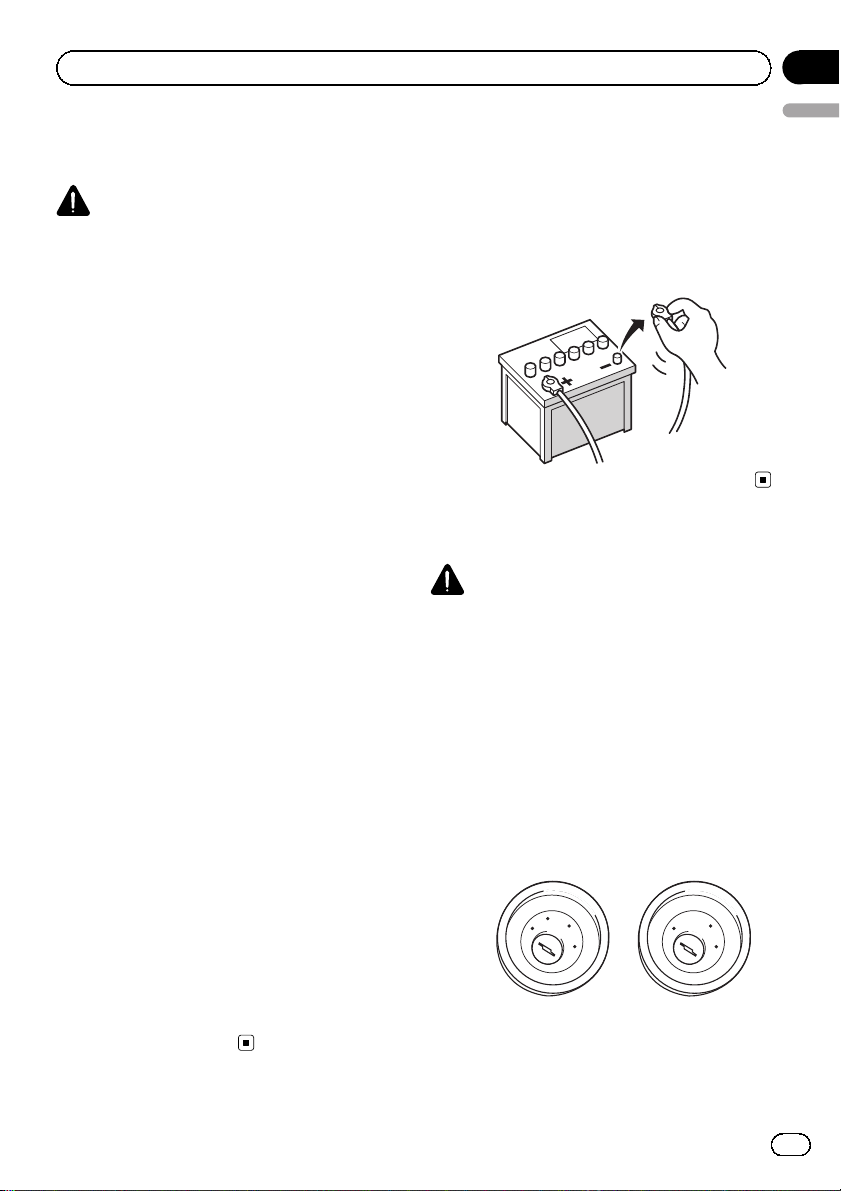
! To avoid shorts in the electrical system, be
sure to disconnect the (–) battery cable before beginning installation.
To prevent damage
WARNING
! Use speakers over 50 W (output value)
and between 4 W to 8 W (impedance value).
Do not use 1 W to 3 W speakers for this
unit.
! When replacing the fuse, be sure to only
use a fuse of the rating prescribed on this
product.
! When disconnecting a connector, pull the
connector itself. Do not pull the lead, as
you may pull it out of the connector.
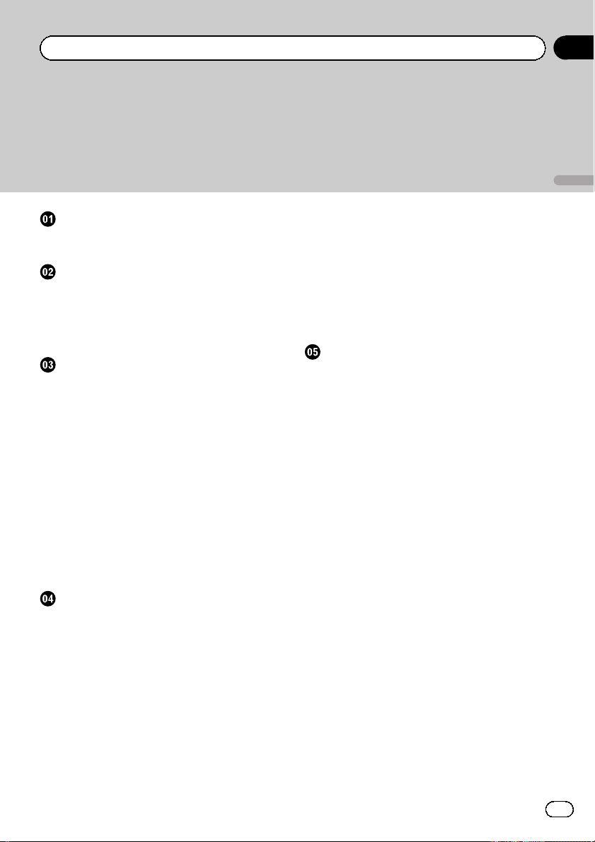
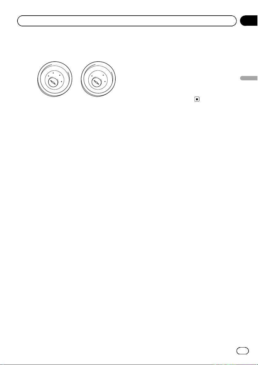
! This product cannot be installed in a vehi-
cle without ACC (accessory) position on
the ignition switch.
C
C
A
O
F
N
F
O
ACC position No ACC position
S
T
A
R
T
O
F
N
F
O
S
T
A
R
T
Section
03
English
Engb
5
Page 6
Section
03
Connecting the system
! To avoid short-circuiting, cover the discon-
nected lead with insulating tape. It is espe-
cially important to insulate all unused
speaker leads, which if left uncovered may
cause a short circuit.
! Refer to the owner’s manual for details on
connecting the power amp and other units,
then make connections accordingly.
! Since a unique BPTL circuit is employed,
do not directly earth the * side of the
speaker lead or connect the * sides of the
speaker leads together. Be sure to connect
the * side of the speaker lead to the *
side of the speaker lead on this navigation
system.
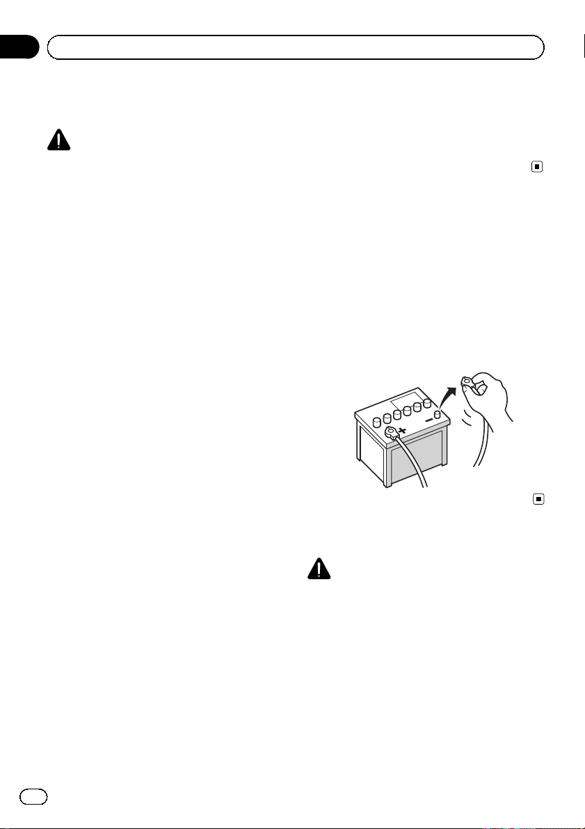
Notice for the blue/white lead
! When this unit is turned on, a control sig-
nal is output through the blue/white cable.
Connect it to an external power amp’s sys-
tem remote control or the vehicle’s auto-
aerial relay control terminal (max. 300 mA,
12 V DC). If the vehicle is equipped with a
glass aerial, connect the cable to the aerial
booster power supply terminal.
! Never connect the blue/white cable to an
external power amp’s power terminal. Also,
never connect it to the power terminal of
the auto aerial. Otherwise, battery drain or
malfunction may result.
! Be sure not to use this lead as the power
supply lead for the auto-aerial or aerial
booster. Such connection could cause ex-
cessive current drain and malfunction.
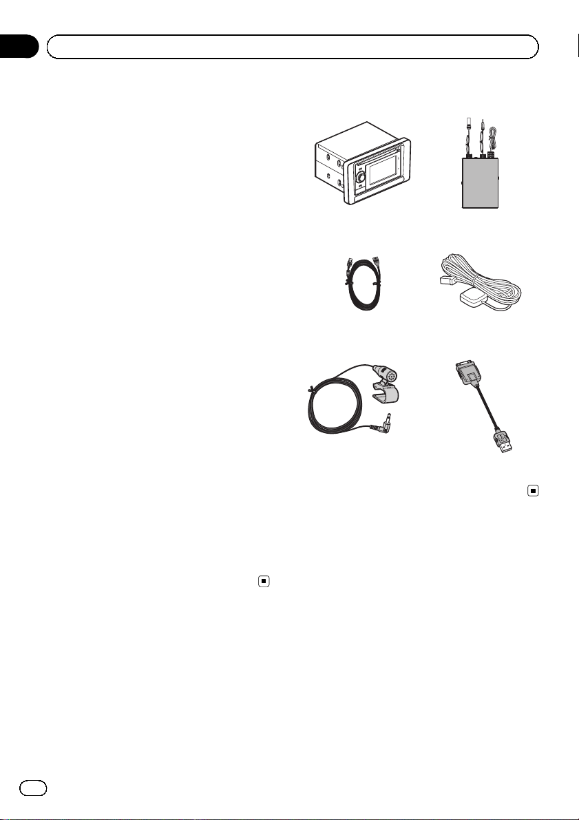
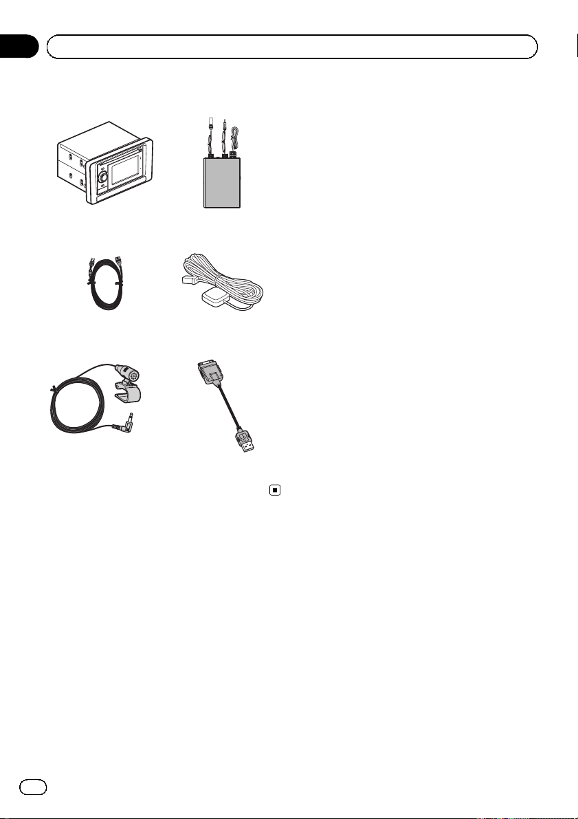
Parts supplied
Navigation unit RDS-TMC tuner
USB cable GPS aerial
Microphone USB interface cable for
iPod
6
Engb
Page 7
Connecting the system
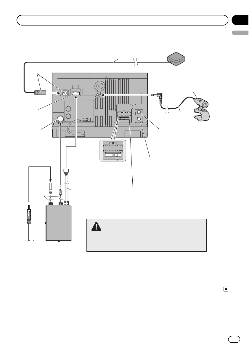
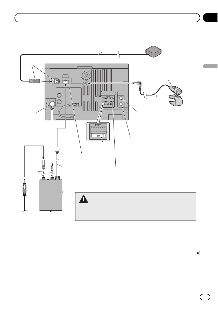
Connecting the system
Green
Navigation unit
Section
03
English
3.55 m
GPS aerial
Microphone
Expansion port
Aerial jack
30 cm
Vehicle
aerial
RDS-TMC tuner
AUX jack
Use a stereo mini plug cable
to connect with auxiliary
device.
WIRED REMOTE INPUT
Please see the Instruction
Manual for the Wired Remote
Control Adapters (sold separately).
1 m
Fuse (10 A)
Power cord
For connection, refer to the wiring and installation
manual separately supplied.
WARNING
To avoid the risk of accident and the potential violation of
applicable laws, this product should never be used while
the vehicle is being driven except for navigation purposes.
4 m
Engb
7
Page 8
Section
03
Connecting the system
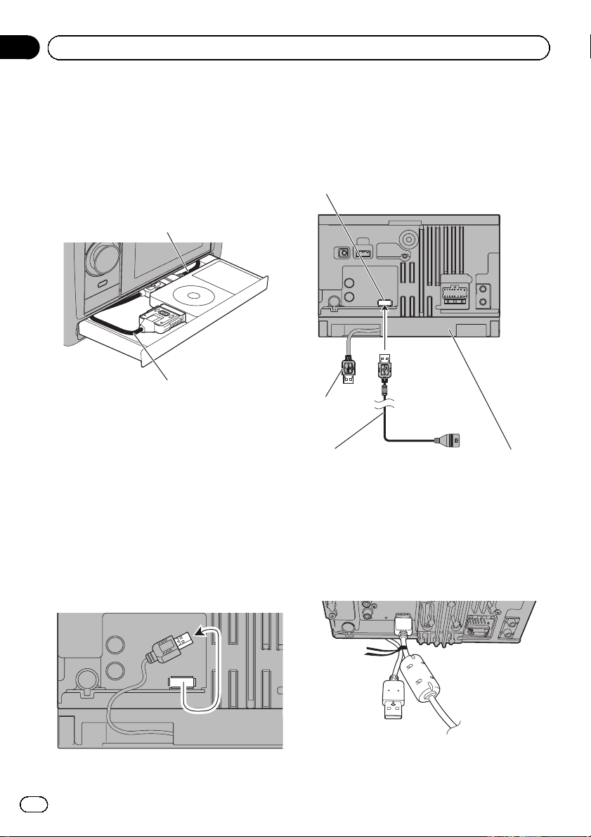
USB connection
Using the USB connector in the
drawer
You can connect either the USB interface
cable for iPod or an appropriate USB storage
device using the USB connector in the drawer.
USB connector
USB interface cable for iPod (supplied)
= For details, refer to Operation Manual.
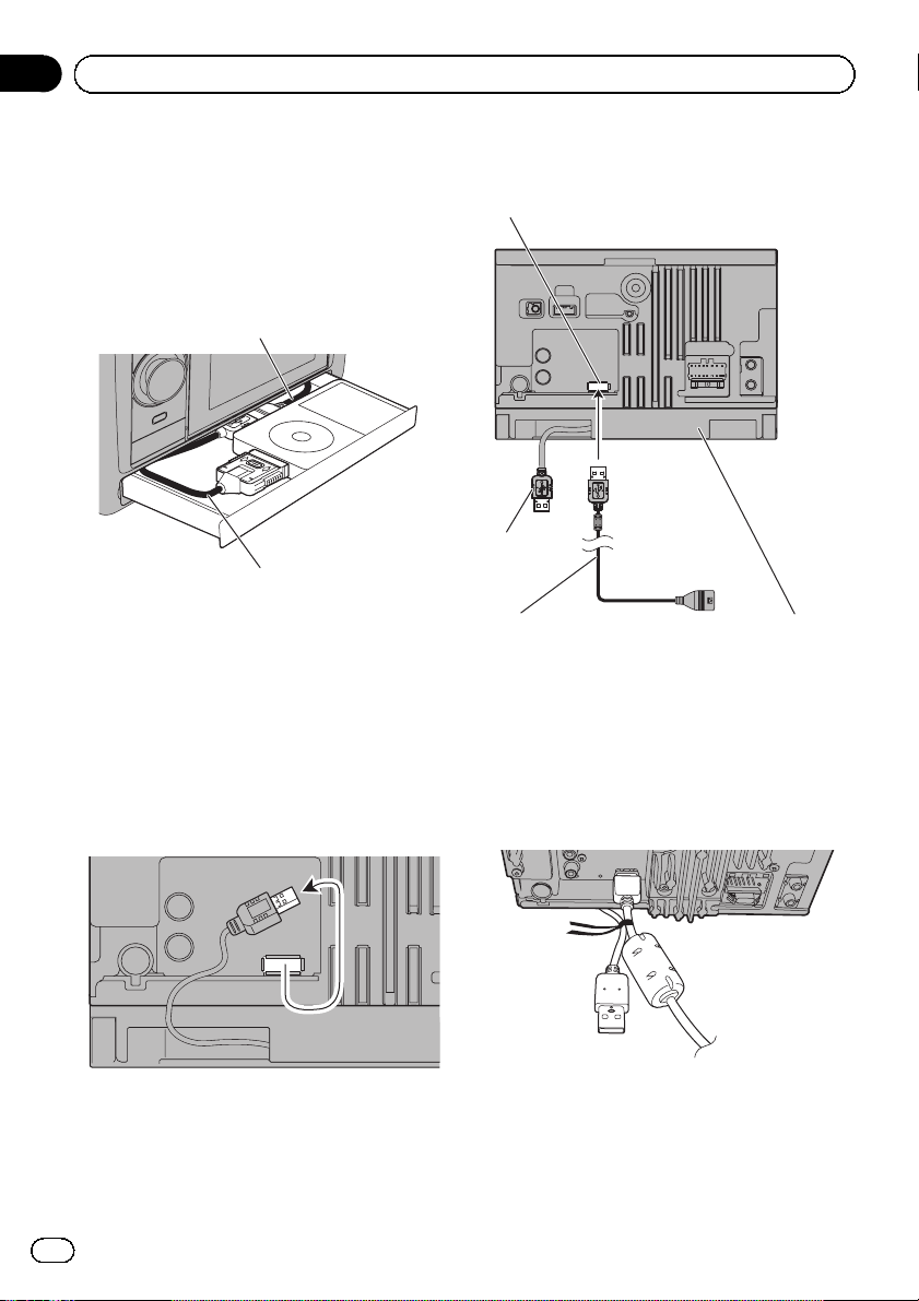
Using the supplied USB cable
If the drawer cannot be used due to the dimensions of the iPod or USB storage device, you
can connect them using the USB cable supplied.
1 Unplug the fixed USB cable from the
USB port on the rear.
2 Connect the supplied USB cable to the
USB port.
USB port
Not used.
1.5 m
USB cable (supplied) Navigation unit
3 Tie together the fixed USB cable and
the supplied USB cable with the twist tie.
Use the twist tie that came around the supplied USB cable to bind the two USB cables
together.
p To prevent the fixed USB cable from becom-
ing entangled by anything at the rear, bind
it to the other USB cable.
p When the fixed USB cable on the rear is un-
plugged, the USB connector in the drawer
will not work.
8
Engb
Page 9
Connecting the system
Section
03
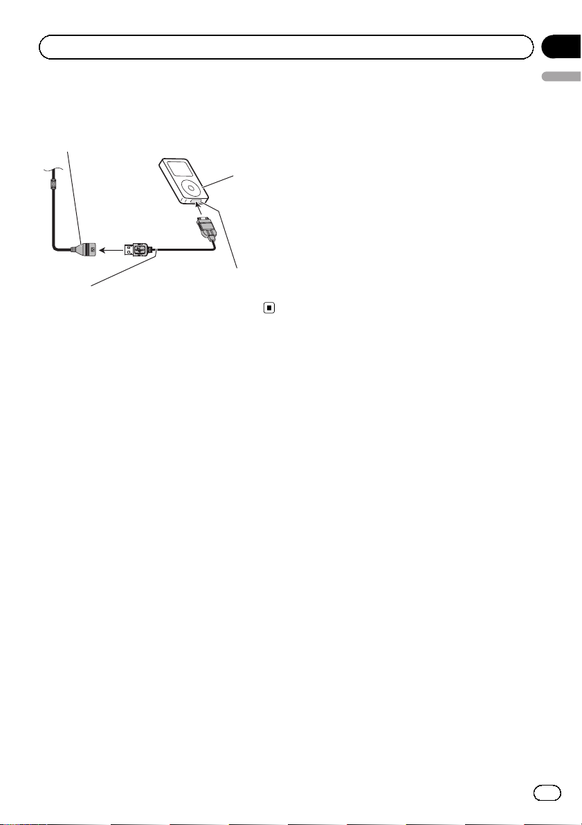
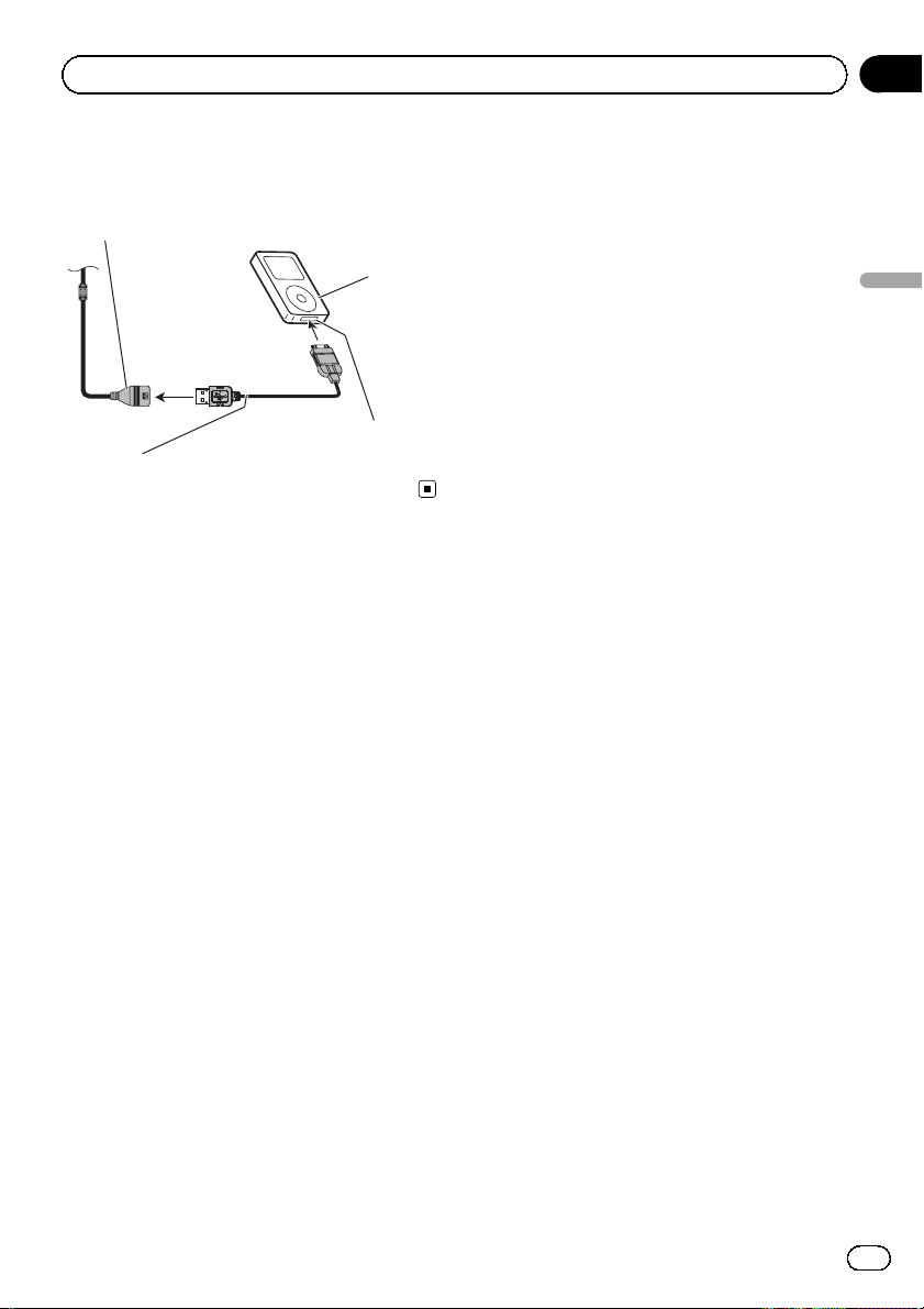
4 Connect either the USB interface cable
for iPod or an appropriate USB storage device to the USB connector.
USB connector
iPod with
Dock connector
7.5 cm
Dock connector port
USB interface cable for iPod (supplied)
English
Engb
9
Page 10
Section
03
Connecting the system
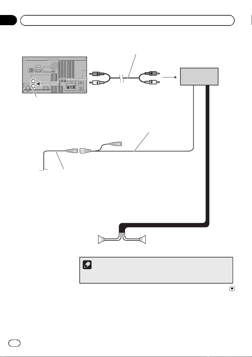
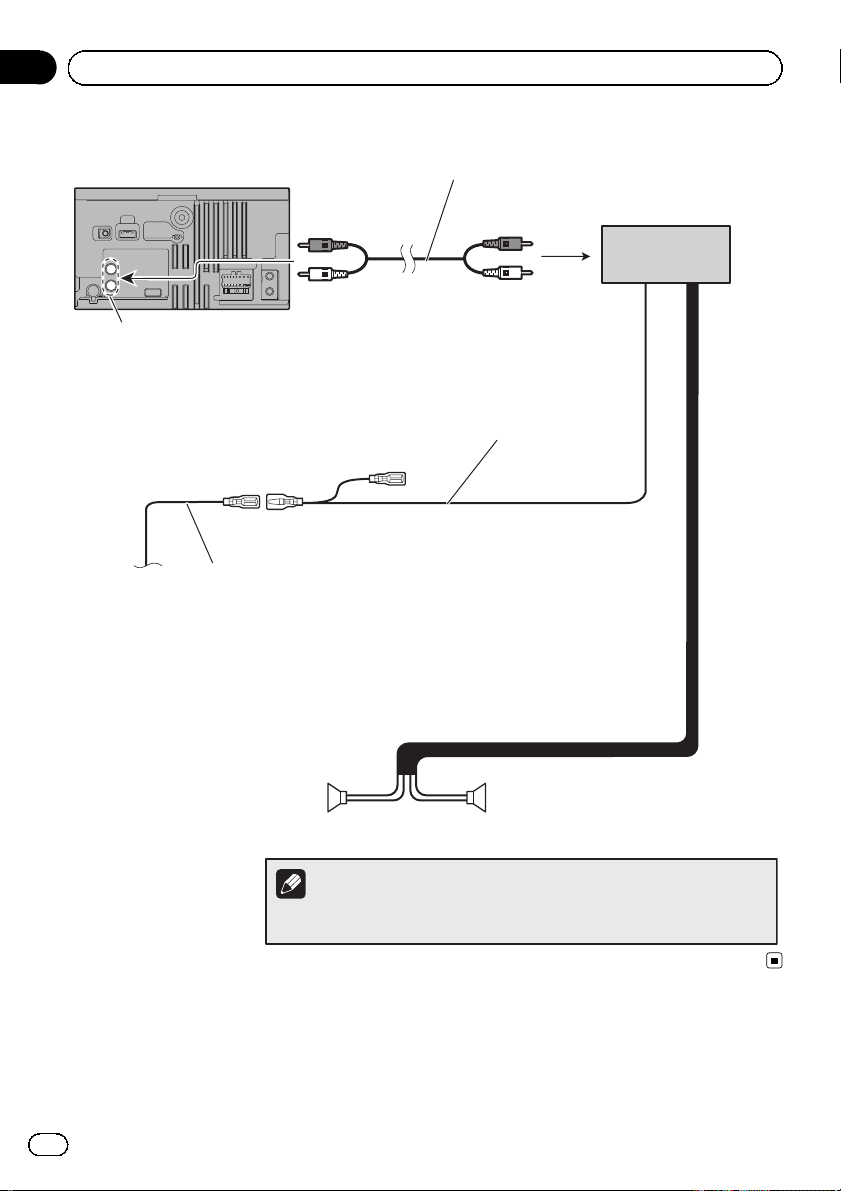
When connecting to separately sold power amp
Navigation unit
Rear or Subwoofer output
Blue/white
To system control terminal of the power amp (max. 300 mA 12 V DC).
For connection, refer to the wiring and installation manual
separately supplied.
RCA cable
(sold separately)
System remote control
Power amp
(sold separately)
10
Engb
Rear speaker or
Subwoofer
Rear speaker or
Subwoofer
Left Right
Note
You can change the RCA output of the subwoofer depending on your subwoofer
system. (Refer to Operation Manual.)
Page 11

Installation
Section
04
Precautions before
installation
CAUTION
! Never install this product in places where,
or in a manner that:
— It could injure the driver or passengers
if the vehicle stops suddenly.
— It may interfere with the driver’s opera-
tion of the vehicle, such as on the floor
in front of the driver’s seat, or close to
the steering wheel or gearstick.
! Make sure there is nothing behind the
dashboard or panelling when drilling
holes in them. Be careful not to damage
fuel lines, brake lines, electronic components, communication wires or power
cables.
! When using screws, do not allow them to
come into contact with any electrical lead.
Vibration may damage wires or insulation,
leading to a short circuit or other damage
to the vehicle.
! To ensure proper installation, be sure to
use the supplied parts in the manner specified. If any parts are not supplied with
this product, use compatible parts in the
manner specified after you have the parts’
compatibility checked by your dealer. If
parts other than supplied or compatible
ones are used, they may damage internal
parts of this product or they may work
loose and the product may become detached.
! It is extremely dangerous to allow the
cables to become wound around the steering column or gearstick. Be sure to install
this product, its cables, and wiring away
in such a way that they will not obstruct
or hinder driving.
! Make sure that leads cannot get caught in
a door or the sliding mechanism of a seat,
resulting in a short circuit.
! Please confirm the proper function of
your vehicle’s other equipment following
installation of the navigation system.
! Do not install this navigation system
English
where it may (i) obstruct the driver’s vision, (ii) impair the performance of any of
the vehicle’s operating systems or safety
features, including airbags, hazard lamp
buttons or (iii) impair the driver’s ability
to safely operate the vehicle.
! Install the navigation system between the
driver’s seat and front passenger seat so
that it will not be hit by the driver or passenger if the vehicle stops quickly.
! Never install the navigation system in
front of or next to the place in the dash,
door, or pillar from which one of your vehicle’s airbags would deploy. Please refer to
your vehicle’s owner’s manual for reference to the deployment area of the frontal
airbags.
To guard against
electromagnetic interference
In order to prevent interference, set the following items as far as possible from this navigation system, other cables or leads:
! FM, MW/LW aerial and its lead
! GPS aerial and its lead
In addition you should lay or route each aerial
lead as far as possible from other aerial leads.
Do not bind them together, lay or route them
together, or cross them. Such electromagnetic
noise will increase the potential for errors in
the location display.
Before installing
! Consult with your nearest dealer if installa-
tion requires the drilling of holes or other
modifications of the vehicle.
! Before making a final installation of this
product, temporarily connect the wiring to
confirm that the connections are correct
and the system works properly.
Engb
11
Page 12
Section
04
Installation
Installing the navigation
system
Installation notes
! Do not install the navigation system in
places subject to high temperatures or humidity, such as:
— Places close to a heater, vent or air con-
ditioner.
— Places exposed to direct sunlight, such
as on top of the dashboard.
— Places that may be exposed to rain,
such as close to the door or on the vehicle’s floor.
! Install this navigation system in an area
strong enough to bear its weight. Choose a
position where this navigation system can
be firmly installed, and install it securely. If
this navigation system is not securely installed, the current location of the vehicle
cannot be displayed correctly.
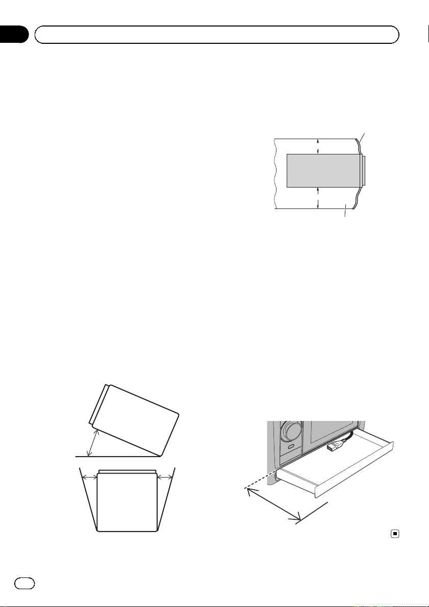
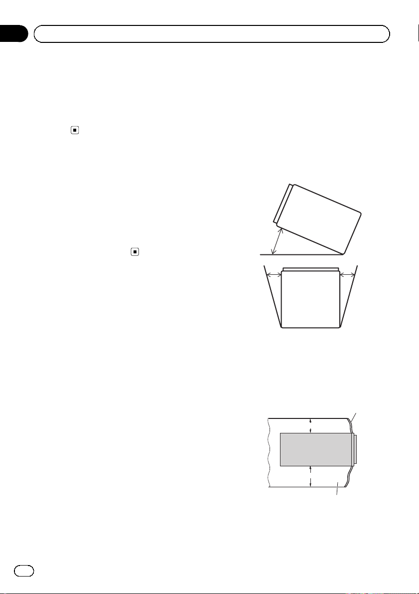
! Install the navigation unit horizontally on a
surface within 0 degrees to 30 degrees tolerance (within 10 degrees to the left or
right). Improper installation of the unit with
the surface tilted more than these tolerances increases the potential for errors in
the location display, and might otherwise
cause reduced display performance.
! When installing, to ensure proper heat dis-
persal when using this unit, make sure you
leave ample space behind the rear panel
and wrap any loose cables so they are not
blocking the vents.
Dashboard
5 cm
10 cm
Leave ample space
! The semiconductor laser will be damaged
if it overheats, so don’t install the navigation unit anywhere hot —for instance, near
a heater outlet.
! Do not install this navigation system where
it is difficult to remove the detachable device from the head unit or open the drawer
due to being encumbered by the gear stick
or any other objects. Before installing this
navigation system, be sure to leave sufficient space so that the detachable device
or the drawer does not prevent the operation of the gear stick when the detachable
device is detached or the drawer opened.
Otherwise, these may cause interference
with the gear stick, or a malfunction of the
detaching mechanism.
12
30°
10° 10°
9 cm to 10 cm
Engb
Page 13

Installation
Concealing the metal brackets
Use the supplied self-adhesive sheets to hide
the metal brackets inside that are visible from
the front panel slits.
Section
04
English
Self-adhesive sheet
(4 pcs.)
1 Peel the release paper off the sheets.
2 Attach the sheets at the top and bottom on both sides of the panel as illustrated below.
Fixing the detachable device
A fixing screw is used for the in-store display.
2 Fix the detachable device to the head
unit using the fixing screw.
3 Reattach the side brackets and tighten
the screws.
Fixing screw
(1 pc.)
1 Remove the side brackets.
Loosen the screws to remove the side brackets.
Engb
13
Page 14
Section
04
Installation
Installing the GPS aerial
CAUTION
Do not cut the GPS aerial lead to shorten it
or use an extension to make it longer. Altering the aerial cable could result in a short circuit or malfunction and permanent damage
to the navigation system.
Installation notes
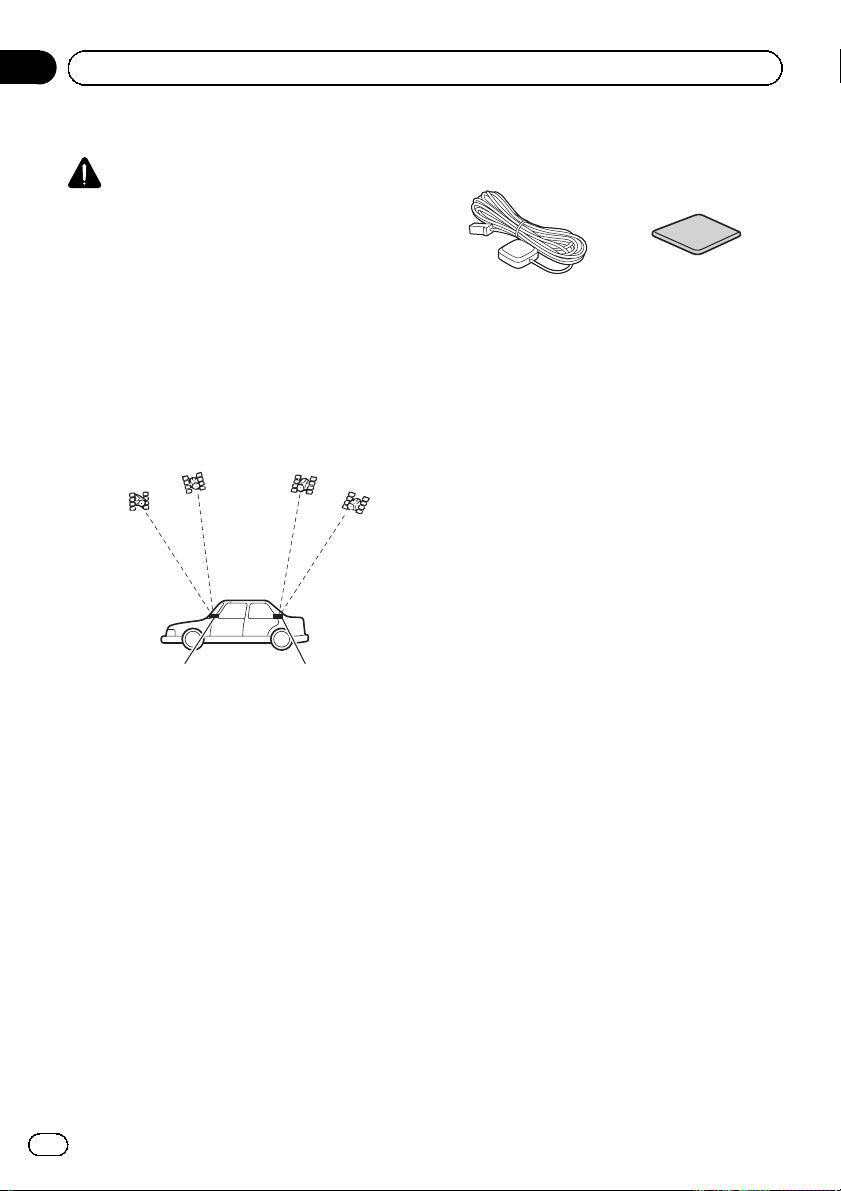
! The aerial should be installed on a level sur-
face where radio waves will be blocked as
little as possible. Radio waves cannot be received by the aerial if reception from the satellite is blocked.
Dashboard Rear shelf
! When installing the GPS aerial inside the
vehicle, be sure to use the metal sheet provided with your system. If this is not used,
the reception sensitivity will be poor.
! Do not cut the accessory metal sheet. This
would reduce the sensitivity of the GPS aerial.
! Take care not to pull the aerial lead when
removing the GPS aerial. The magnet attached to the aerial is very powerful, and
the lead may become detached.
! Do not paint the GPS aerial, as this may af-
fect its performance.
Parts supplied
GPS aerial Metal sheet
14
Engb
Page 15
Installation
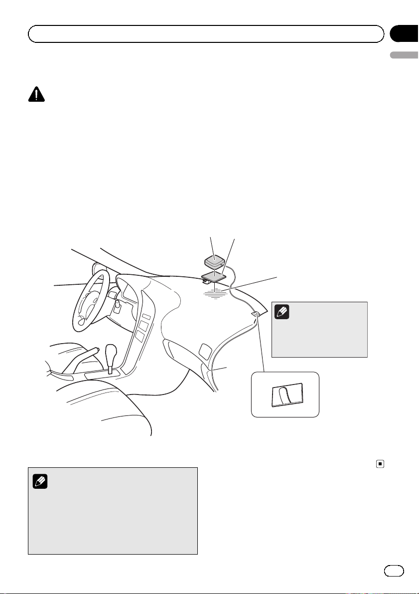
When installing the aerial inside the vehicle (on the dashboard or
rear shelf)
WARNING
Do not install the GPS aerial over any sensors or vents on the dashboard of the vehicle,
as doing so may interfere with the proper
functioning of such sensors or vents and may
compromise the ability of the metal sheet
under the GPS aerial to properly and securely affix to the dashboard.
Affix the metal sheet on as level a surface as
possible where the GPS aerial faces the window. Place the GPS aerial on the metal sheet.
(The GPS aerial is fastened with its magnet.)
GPS aerial
Metal sheet
Peel off the protective sheet
on the rear.
Make sure the surface is
free of moisture, dust,
grime, oil, etc., before
affixing the metal sheet.
Section
04
English
Notes
! When attaching the metal sheet, do not cut
it into small pieces.
! Some models use window glass that does
not allow signals from GPS satellites to
pass through. On such models, install the
GPS aerial on the outside of the vehicle.
Note
The metal sheet contains a
strong adhesive which may
leave a mark on the surface if
it is removed.
Clamps
Use separately sold clamps
to secure the lead where necessary
inside the vehicle.
Engb
15
Page 16
Section
04
Installation
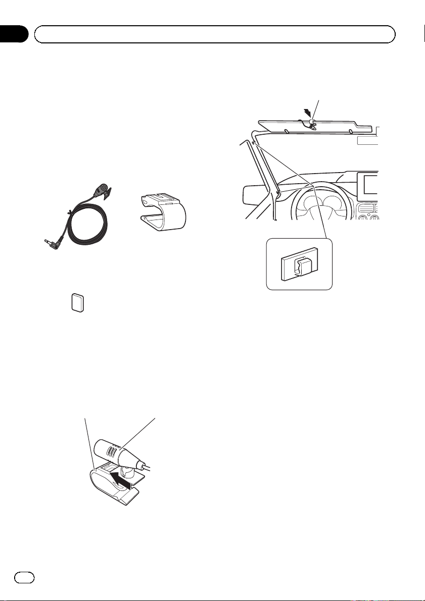
Installing the microphone
! Install the microphone in a place where its
direction and distance from the driver
make it easiest to pick up the driver’s voice.
! Make sure to connect the microphone to
the navigation system after the system is
turned off. (ACC OFF)
Parts supplied
Microphone Microphone clip
Double-sided tape
Mounting on the sun visor
1 Install the microphone in the microphone clip.
Microphone clip Microphone
2 Attach the microphone clip to the sun
visor.
Microphone clip
Clamps
Use separately sold clamps
to secure the lead where necessary inside the vehicle.
Install the microphone on the sun visor when
it is in the up position. It cannot recognise the
driver’s voice if the sun visor is in the down position.
16
Engb
Page 17
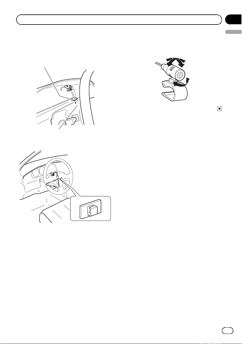
Installation
Installation on the steering column
% Mount the microphone on the steering
column.
Double-sided tape
Install the microphone on the
steering column, keeping it away
from the steering wheel.
Section
04
English
Adjusting the microphone angle
The microphone angle can be adjusted.
Clamps
Use separately sold
clamps to secure the
lead where necessary inside the vehicle.
Engb
17
Page 18
Section
05
After installation
After installing this
navigation system
1 Reconnect the negative (–) terminal of
the vehicle’s battery.
First, double-check that all connections are
correct and that this product is installed correctly. Reassemble all vehicle components
that you previously removed. Then reconnect
the negative (–) cable to the negative (–) terminal of the battery.
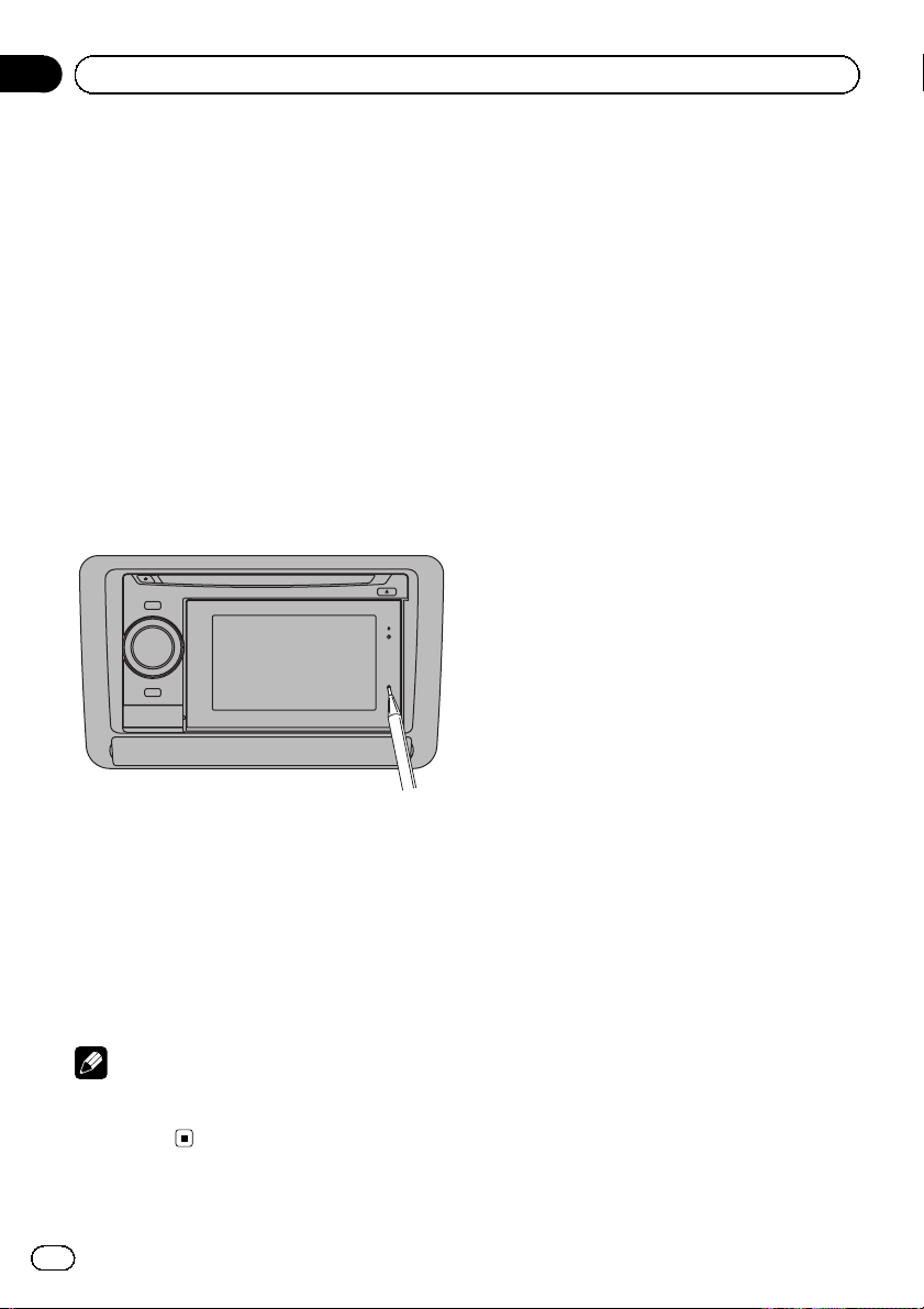
2 Start the engine.
3 Press the RESET button while the detachable device is attached.
Press the RESET button on the navigation unit
with a pointed object such as the tip of a pen.
4 Make the following settings.
= For details concerning operations, refer to
Operation Manual.
1 Set the language.
2 Drive an unobstructed road until the GPS
starts receiving the signal normally.
3 Make some necessary adjustments.
! Setting the time
! Change other settings as you prefer
Note
After installing this navigation system, be sure to
check at a safe place that the vehicle is performing normally.
18
Engb
Page 19
Índice
Español
INFORMACIÓN IMPORTANTE
ACERCA DE SU NUEVO SISTEMA DE
NAVEGACIÓN Y ESTE MANUAL 20
PRECAUCIONES IMPORTANTES
LEA TODAS ESTAS INSTRUCCIONES
RELACIONADAS CON SU SISTEMA DE
NAVEGACIÓN Y GUÁRDELAS PARA
EMPLEARLAS COMO REFERENCIA EN EL
FUTURO 21
Conexión del sistema
Precauciones antes de conectar el
sistema 22
Antes de instalar este producto 22
Para impedir daños 22
– Aviso para el cable conductor azul/
blanco 23
Partes suministradas 24
Conexión del sistema 25
Conexión USB 26
– Utilización del conector USB del
compartimiento 26
– Utilización del cable USB
suministrado 26
Conexión al amplificador de potencia que se
vende por separado 28
Instalación
Precauciones antes de la instalación 29
Para impedir que se produzcan
interferencias electromagnéticas 29
Antes de la instalación 30
Instalación del sistema de navegación 30
– Notas acerca de la instalación 30
Cómo ocultar los soportes metálicos 31
Fijación del dispositivo extraíble 31
Instalación de la antena GPS 33
– Notas acerca de la instalación 33
– Partes suministradas 33
– Cuando instale la antena en el interior
del vehículo (en el salpicadero o en la
bandeja trasera) 34
Instalación del micrófono 35
– Partes suministradas 35
– Montaje en el parasol 35
– Instalación en la columna de
dirección 36
– Ajuste del ángulo del micrófono 37
Después de la instalación
Después de instalar este sistema de
navegación 38
19
Es
Page 20

Sección
01
INFORMACIÓN IMPORTANTE
ACERCA DE SU NUEVO
SISTEMA DE NAVEGACIÓN Y
ESTE MANUAL
! Las funciones de navegación de este pro-
ducto están pensadas únicamente para
ayudarle en el manejo de su vehículo. De
ninguna forma deben considerarse como
un sustituto de su atención, buen juicio y
cuidado durante la conducción.
! Nunca utilice este sistema de navegación
para guiarse hasta hospitales, comisarías
de policía o instalaciones parecidas si se
produce una emergencia. En tal caso,
llame al número de emergencias correspondiente.
! No active el sistema de navegación si al ha-
cerlo deja de prestar atención y pone en peligro el manejo seguro de su vehículo. Las
limitaciones y consejos sobre el tráfico
existentes en cada momento deben tomarse siempre con prioridad respecto a la guía
que proporciona este producto. Haga caso
siempre de las limitaciones de tráfico existentes en cada momento, aunque este producto aconseje lo contrario.
! Este manual explica cómo instalar este sis-
tema de navegación en su vehículo. Sin
embargo, en el manual de instalación independiente se describe parte del proceso de
cableado e instalación. El funcionamiento
de este sistema de navegación se explica
en un manual independiente.
! No instale este producto en puntos en los
que pueda (i) dificultar la visión del conductor, (ii) comprometer el funcionamiento
de alguno de los sistemas de seguridad del
vehículo, como los airbags, los botones de
los indicadores de peligro, o (iii) comprometer la capacidad del conductor para manejar el vehículo con seguridad. En
algunos casos, es posible que este producto no pueda instalarse debido al tipo de vehículo o a la forma del interior del
vehículo.
20
Es
Page 21

PRECAUCIONES IMPORTANTES
Sección
02
ADVERTENCIA
Pioneer aconseja que no realice usted mismo
la instalación del sistema de navegación. Recomendamos que sólo el personal de servicio
autorizado de Pioneer, que cuenta con formación especializada y experiencia en el campo
de la electrónica móvil, instale y configure
este producto. NUNCA EFECTÚE EL MANTENIMIENTO DE ESTE PRODUCTO USTED
MISMO. La instalación o el mantenimiento
del producto y de los cables de conexión asociados puede exponerle al riesgo de una descarga eléctrica u otros peligros, y puede
ocasionar daños en el sistema de navegación
que no cubre la garantía.
LEA TODAS ESTAS
INSTRUCCIONES
RELACIONADAS CON SU
SISTEMA DE NAVEGACIÓN Y
GUÁRDELAS PARA
EMPLEARLAS COMO
REFERENCIA EN EL FUTURO
1 Lea completa y detenidamente este manual
antes de instalar su sistema de navegación.
2 Guarde al alcance de la mano este manual
para utilizarlo como referencia en el futuro.
3 Ponga mucha atención a todas las adverten-
cias de este manual y siga cuidadosamente
las instrucciones.
4 La primera vez que se inicie el sistema, podría
aparecer el sistema “Preparing to start up
system...please wait”, dado que la carga res-
tante en la batería podría ser muy reducida. Si
aparece este mensaje, no efectúe ninguna acción hasta que no se muestre el mensaje
“Ready to start up system.”.
5 En ciertas circunstancias, este sistema de na-
vegación puede mostrar una información
errónea de la posición de su vehículo, la distancia de los objetos mostrados en la pantalla
y las direcciones de la brújula. Además, el sis-
tema tiene ciertas limitaciones, incluyendo la
incapacidad de identificar calles de una dirección, restricciones temporales de tráfico y
zonas donde la conducción pueda resultar peligrosa. Haga uso de su buen juicio en función de las condiciones de conducción reales.
6 Al igual que con cualquier otro accesorio del
interior, el sistema de navegación nunca deberá distraerle ni poner en peligro el manejo seguro de su vehículo. Si encuentra dificultades
al utilizar el sistema o al leer la pantalla, haga
los ajustes necesarios con el vehículo estacionado en un lugar seguro.
7 Recuerde ponerse siempre el cinturón de se-
guridad cuando maneje su vehículo. En el
caso de sufrir un accidente, sus lesiones pueden ser mucho más graves si no tiene bien
puesto su cinturón de seguridad.
8 Algunos países y leyes gubernamentales pue-
den prohibir o limitar la ubicación y el uso de
este sistema en su vehículo. Cumpla con
todas las leyes y normas pertinentes en cuanto al uso, la instalación y el funcionamiento
del sistema de navegación.
Español
21
Es
Page 22
Sección
03
Conexión del sistema
Precauciones antes de
conectar el sistema
PRECAUCIÓN
! Si decide efectuar la instalación usted
mismo y cuenta con formación especializada y experiencia en la instalación de sistemas electrónicos móviles, siga con
cuidado todos los pasos descritos en el
manual de instalación.
! Asegure todo el cableado con abrazaderas
de cables o cinta para usos eléctricos. No
permita que el cableado pelado permanezca descubierto.
! Es extremamente peligroso permitir que
los cables queden enrollados alrededor de
la columna de la dirección o palanca de
cambio. Asegúrese de instalar este producto, sus cables y hilos alejados, de
forma que no obstruyan o impidan la conducción del vehículo.
! Asegúrese de que todos los cables estén
enrutados y sujetos de manera que no entorpezcan o queden atrapados con alguna
de las partes móviles del vehículo, en especial con el volante, la palanca de cambio, el freno de mano, las guías de los
asientos deslizantes, las puertas o con alguno de los controles del vehículo.
! No enrute cables que vayan a estar some-
tidos a altas temperaturas. Si se calienta
el aislamiento, los cables pueden resultar
dañados y, como consecuencia, puede
producirse un cortocircuito o una avería y
el producto puede sufrir un deterioro permanente.
! No corte el cable de la antena GPS para
reducir su longitud ni utilice una extensión para alargarlo. La alteración del cable
de la antena puede causar un cortocircuito.
! No acorte ningún cable. En el caso de que
lo haga, el circuito de protección (el portafusibles, la resistencia de fusible o el filtro, etc.) puede que no funcione
correctamente.
! Nunca suministre alimentación a otros
productos electrónicos cortando el aislamiento del cable de alimentación del sistema de navegación y tomando corriente
de él. La capacidad nominal del cable se
excederá y causará un recalentamiento.
Antes de instalar este
producto
! Utilice esta unidad solamente con una ba-
tería de 12 voltios y puesta a tierra negativa.
De lo contrario, podrá ocasionar un incendio o un fallo de funcionamiento.
! Para evitar cortocircuitos en el sistema
eléctrico, asegúrese de desconectar el
cable de la batería (–) antes de comenzar
con la instalación.
Para impedir daños
ADVERTENCIA
! Utilice altavoces con capacidad superior a
50 W (valor de salida) y entre 4 W a8W
(valor de impedancia). No utilice altavoces de 1 W a3W para esta unidad.
! Al sustituir el fusible, asegúrese de utili-
zar exclusivamente un fusible del régimen
nominal descrito en este producto.
! Cuando desconecte un conector, tire del
propio conector. No tire del cable porque
podría sacarlo del conector.
22
Es
Page 23
Conexión del sistema
Sección
03
! No se puede instsalar este producto en un
vehículo sin la posición ACC (accesorio)
en el interruptor de encendido.
C
C
A
O
F
N
F
O
Posición ACC Sin posición ACC
S
T
A
R
T
O
F
N
F
O
S
T
A
R
T
! Para evitar cortocircuitos, cubra el conduc-
tor desconectado con cinta aislada. Es especialmente importante aislar todos los
cables de altavoz que no se usen, ya que si
no se recubren pueden llegar a provocar
un cortocircuito.
! Consulte el manual del propietario para ob-
tener información sobre la conexión del
amplificador de potencia y de otras unidades y, a continuación, realice las conexiones de manera acorde.
! Como se utiliza un circuito BPTL único, no
conecte directamente a tierra el extremo *
del cable del altavoz, ni conecte juntos los
extremos * de los cables de los altavoces.
Asegúrese de conectar el extremo * del
cable del altavoz al extremo * del cable
del altavoz de este sistema de navegación.
modo, nunca lo conecte al terminal de alimentación de la antena automática. De lo
contrario, podría agotar carga de batería o
producirse fallos de funcionamiento.
! Asegúrese de utilizar este cable conductor
como el cable conductor del suministro de
energía para la antena automática o amplificador de antena. Tal conexión podría causar un drenaje excesivo de corriente y un
fallo de funcionamiento.
Español
Aviso para el cable conductor
azul/blanco
! Al encender esta unidad se emite una
señal de control a través del cable azul/
blanco. Conéctelo al control remoto de un
sistema de amplificación de potencia externo, o al terminal de control de relé de antena automática del vehículo (max. 300 mA,
12 V cc). Si el vehículo está equipado con
una antena para cristal, conecte el cable al
terminal de suministro eléctrico del amplificador de antena.
! No conecte nunca el cable azul/blanco a
un terminal de alimentación de un amplificador de potencia externo. Del mismo
23
Es
Page 24
Sección
03
Conexión del sistema
Partes suministradas
Unidad de navegación Sintonizador RDS-TMC
Cable USB Antena GPS
24
Micrófono Cable de interfaz USB
para iPod
Es
Page 25
Conexión del sistema
Conexión del sistema
Verd e
Unidad de navegación
Sección
03
3,55 m
Antena GPS
Español
Micrófono
4 m
Toma para
antena
30 cm
Antena del
vehículo
Sintonizador
RDS-TMC
Toma AU X
Utilice un cabo con mini
clavija estéreo para conectar
el dispositivo auxiliar.
WIRED REMOTE INPUT
Consulte el manual de instrucciones
para los adaptadores de control remoto
por cable (se venden por separado).
Puerto de expansión
1 m
Fusible (10 A)
Cable de alimentación
Para el proceso de conexión, consulte el
manual de cableado e instalación
independiente suministrado.
ADVERTENCIA
Para evitar el riesgo de accidente y la violación potencial de las leyes
aplicables, nunca se debe utilizar este producto durante la
conducción del vehículo, excepto para los propósitos de navegación.
25
Es
Page 26
Sección
03
Conexión del sistema
Conexión USB
Utilización del conector USB del
compartimiento
Puede utilizar tanto el cable de interfaz USB
para iPod o un dispositivo de almacenamiento
USB correspondiente utilizando el conector
USB del compartimiento.
Conector USB
Cable de interfaz USB para iPod (suministrado)
= Para obtener los detalles, consulte el Ma-
nual de operación.
Utilización del cable USB
suministrado
Si no es posible utilizar el compartimiento debido a las dimensiones del iPod o el dispositivo de almacenamiento USB, podrá
conectarlos utilizando el cable USB suministrado.
1 Desconecte el cable USB fijo del puerto
USB de la parte trasera.
p Cuando se desconecte el cable USB fijo de
la parte trasera, el conector USB del compartimiento no funcionará.
2 Conecte el cable USB suministrado al
puerto USB.
Puerto USB
No se
utiliza.
1,5 m
Cable USB (suministrado) Unidad de navegación
3 Enlace juntos el cable USB fijo y el cable
USB suministrado con la abrazadera.
Utilice la abrazadera que incluye el cable USB
suministrado para enlazar los dos cables
USB.
p Para impedir que el cable USB fijo se enre-
de con algún elemento de la parte trasera,
únalo al otro cable USB.
26
Es
Page 27
Conexión del sistema
4 Conecte el cable de interfaz USB para
iPod o un dispositivo de almacenamiento
USB adecuado al conector USB.
Conector USB
iPod con Conector
de acoplamiento
7,5 cm
Puerto de conector
de acoplamiento
Cable de interfaz USB para iPod (suministrado)
Sección
03
Español
27
Es
Page 28
Sección
03
Conexión del sistema
Conexión al amplificador de potencia que se vende por separado
Unidad de navegación
Salida de Altavoz trasero o Altavoz de graves
Azul/blanco
Al terminal de control del sistema del amplificador de potencia
(máx. 300 mA 12 V CC).
Para el proceso de conexión, consulte el manual de cableado e
instalación independiente suministrado.
Cable RCA
(se vende por separado)
Amplificador de
potencia (se vende
por separado)
Control remoto de sistema
28
Izquierda Derecha
Altavoz trasero o
Altavoz de graves
Altavoz trasero o
Altavoz de graves
Nota
Se puede cambiar la salida RCA del altavoz de graves dependiendo del sistema
de altavoz de graves. (Consulte el Manual de operación.)
Es
Page 29

Instalación
Sección
04
Precauciones antes de la
instalación
PRECAUCIÓN
! Nunca instale este producto en lugares en
los que, o de manera que:
— Pueda lesionar al conductor o a los pa-
sajeros si el vehículo se detiene bruscamente.
— Pueda entorpecer el manejo del ve-
hículo por parte del conductor, por
ejemplo en el piso delante del asiento
del conductor o cerca del volante o de
la palanca de cambio.
! Asegúrese de que no haya nada detrás del
tablero de instrumentos u otros paneles al
taladrar agujeros en ellos. Tenga cuidado
de no dañar conductos de combustible,
tuberías de freno, componentes electrónicos, cables de alimentación y de comunicaciones.
! Cuando utilice tornillos no permita que
éstos entren en contacto con ningún cable
eléctrico. La vibración puede deteriorar
los cables o el aislamiento y provocar un
cortocircuito u otros daños en el vehículo.
! Para asegurar una instalación apropiada,
utilice las piezas suministradas de la
forma especificada. Si no se suministran
piezas con este producto, utilice piezas
compatibles de la forma especificada después de haber comprobado a través de su
distribuidor la compatibilidad de dichas
piezas. Si utiliza otras piezas que no
hayan sido suministradas o las que no
sean compatibles, éstas podrán estropear
las piezas internas del producto, o podrán
aflojarse y hacer que se desprenda el producto.
! Es extremamente peligroso permitir que
los cables queden enrollados alrededor de
la columna de la dirección o palanca de
cambio. Asegúrese de instalar este producto, sus cables y hilos alejados, de
forma que no obstruyan o impidan la conducción del vehículo.
! Asegúrese de que los cables no queden
atrapados en una puerta ni en el mecanismo de deslizamiento de un asiento porque
puede producirse un cortocircuito.
! Después de instalar el sistema de navega-
ción, compruebe que todos los demás
equipos de su vehículo funcionan correctamente.
! No instale este sistema de navegación en
puntos en los que pueda (i) dificultar la visión del conductor, (ii) comprometer el
funcionamiento de alguno de los sistemas
de seguridad del vehículo, como los airbags, los botones de los indicadores de
peligro, o (iii) comprometer la capacidad
del conductor para manejar el vehículo
con seguridad.
! Instale el sistema de navegación entre el
asiento del conductor y el asiento del pasajero delantero de manera que no sufra
ningún golpe por parte del conductor o
del pasajero en el caso de que el vehículo
frene bruscamente.
! No instale nunca el sistema de navega-
ción en la frente o cerca del sitio en el tablero de instrumentos, puerta o pilar
donde un airbag del vehículo podría desplegarse. Consulte el manual del propietario de su vehículo para las referencias
acerca de las áreas de despliegue de los
airbags delanteros.
Para impedir que se
produzcan interferencias
electromagnéticas
Para evitar interferencias, instale los siguientes elementos lo más lejos posible del sistema
de navegación, así como de otros cables:
! La antena FM, MW/LW y su cable
! La antena GPS y su cable
Español
29
Es
Page 30
Sección
04
Instalación
Además debería colocar o enrutar cada cable
de antena lo más alejado posible de otros cables de antena. No los ate, ni los coloque o enrute juntos, ni tampoco los cruce. El ruido
electromagnético aumentará las posibilidades
de que se produzcan errores en la pantalla de
situación.
Antes de la instalación
! Consulte con su distribuidor si la instala-
ción requiere del taladro de orificios u otras
modificaciones del vehículo.
! Antes de realizar la instalación final de este
producto, conecte el cableado temporalmente y asegúrese de que todo está conectado correctamente y que el sistema
funciona debidamente.
Instalación del sistema de
navegación
Notas acerca de la instalación
! No instale el sistema de navegación en lu-
gares en los que pueda estar expuesto a
altas temperaturas o a humedad, como por
ejemplo:
— Lugares cercanos a un calefactor, con-
ducto de ventilación o aire acondicionado.
— Lugares expuestos a la luz solar directa
tales como el salpicadero.
— Lugares que pudieran verse expuestos a
lluvia, como por ejemplo cerca de una
puerta o en el suelo del vehículo.
! Instale este sistema de navegación en una
zona que sea lo bastante resistente para
soportar su peso. Elija un lugar donde este
sistema de navegación se pueda instalar
bien e instálelo de forma segura. Si el sistema de navegación no está bien instalado,
no se mostrará correctamente la ubicación
actual del vehículo.
! Instale la unidad de navegación de forma
horizontal sobre una superficie dentro de
un margen de tolerancia de 0 grados a 30
grados (en un margen de 10 grados a la izquierda o a la derecha). La incorrecta instalación de la unidad, con la superficie
inclinada más de lo que se indica en estas
instrucciones, aumenta la posibilidad de
que se produzcan errores en la visualización de ubicación, y podría a su vez mermar el rendimiento de la pantalla.
30°
10° 10°
! Cuando instale, para asegurar la dispersión
apropiada del calor durante el uso de esta
unidad, asegúrese de dejar un amplio espacio por detrás del panel trasero y enrolle
cualesquiera cables sueltos de modo que
no bloque en las aberturas de ventilación.
Salpicadero
5 cm
10 cm
Deje un amplio espacio
30
Es
Page 31

Instalación
Sección
04
! El láser de semiconductor quedará dañado
si se sobrecalienta, por tanto no instale la
unidad de navegación en ningún sitio con
calor (por ejemplo, cerca de una salida de
calefacción).
! No instale este sistema de navegación en
un lugar en el que resulte complicado retirar el dispositivo extraíble de la unidad principal o abrir el compartimiento, debido a
las obstrucciones que pudieran presentar
la palanca de cambios o cualquier otro objeto. Antes de instalar este sistema de navegación, asegúrese de dejar espacio
suficiente para que el dispositivo extraíble
o el compartimiento no impida el funcionamiento de la palanca de cambios, al retirar
el dispositivo extraíble o abrir el compartimiento. De lo contrario, podrían interferir
con el movimiento de la palanca de cambios, o provocar fallos de funcionamiento
del mecanismo de retirada.
Cómo ocultar los soportes
metálicos
Utilice las hojas autoadhesivas suministradas
para ocultar los soportes de metal interiores
que pueden verse desde las hendiduras del
panel frontal.
Hoja autoadhesiva
(4 piezas.)
1 Retire el papel de liberación de las
hojas.
2 Coloque las hojas en la parte superior e
inferior, a ambos lados del panel, tal y
como se indica a continuación.
Español
De 9 cm a 10 cm
Fijación del dispositivo
extraíble
Se utiliza un tornillo de fijación para su uso en
expositores de tiendas.
31
Es
Page 32

Sección
04
Instalación
Tornillo de fijación
(1 pieza)
1 Retire los soportes laterales.
Afloje los tornillos para retirar los soportes laterales.
2 Fije el dispositivo extraíble a la unidad
principal por medio del tornillo de fijación.
3 Vuelva a fijar los soportes laterales y
apriete los tornillos.
32
Es
Page 33

Instalación
Sección
04
Instalación de la antena GPS
PRECAUCIÓN
No corte el cable de la antena GPS para reducir su longitud, ni utilice una extensión para
alargarlo. La alteración del cable de la antena
puede provocar un cortocircuito o una avería
y daños permanentes al sistema de navegación.
Notas acerca de la instalación
! La antena debe instalarse en una superfi-
cie nivelada donde las ondas de radio queden bloqueadas lo menos posible. Las
ondas de radio no podrán ser recibidas por
la antena si la emisión desde el satélite
queda bloqueada.
Salpicadero Bandeja trasera
! Cuando instale la antena GPS en el interior
del vehículo, asegúrese de utilizar la hoja
de metálica proporcionada con su sistema.
Si ésta no se utiliza, la sensibilidad de la recepción no será apropiada.
! No corte la hoja de metálica suministrada
para hacerla más pequeña. Esto podría reducir la sensibilidad de la antena GPS.
! Tenga cuidado de no tirar del cable de la
antena cuando quite la antena GPS. El
imán colocado en la antena es muy potente y es posible que el cable se desprenda.
! No pinte la antena GPS ya que puede alte-
rar su rendimiento.
Partes suministradas
Español
Antena GPS Hoja de metal
33
Es
Page 34

Sección
04
Instalación
Cuando instale la antena en el interior del vehículo (en el
salpicadero o en la bandeja trasera)
ADVERTENCIA
No instale la antena GPS sobre sensores o
aberturas de ventilación en el tablero de instrumentos del vehículo, ya que eso puede interferir con el funcionamiento apropiado de
tales sensores o aberturas de ventilación y
puede comprometer la habilidad de adherencia apropiada y segura de la hoja de metal
por debajo de la antena GPS en el tablero de
instrumentos.
Fije la hoja de metal en una superficie lo más
plana posible y donde la antena GPS apunte
hacia la ventana. Ponga la antena GPS en la
hoja de metal. (La antena GPS se fija mediante su imán.)
Antena GPS
Hoja de metal
Desenganche la hoja de
protección de la parte trasera.
Asegurese de que la
superficie no tenga
humedad, polvo, suciedad,
aceite, etc., antes de fijar la
hoja de metal.
34
Nota
La hoja de metal contiene un
adhesivo fuerte que puede
dejar una marca en la
superficie si se quita.
Abrazaderas
Utilice abrazaderas vendidas
separadamente para asegurar
el cable en el interior del vehiculo
donde sea necesario.
Es
Page 35

Instalación
Sección
04
Notas
! Cuando monte la hoja de metal, no la corte
en piezas pequeñas.
! Algunos modelos utilizan ventanas con un
tipo de cristal que no permiten el paso de
las señales procedentes de satélites GPS.
Para tales modelos, instale la antena GPS
en el exterior del vehículo.
Instalación del micrófono
! Instale el micrófono de tal forma que esté
correctamente orientado y a la distancia
correcta del conductor y resulte fácil recoger la voz del conductor.
! Asegúrese de conectar el micrófono al sis-
tema de navegación una vez que el sistema
está apagado. (ACC OFF)
Partes suministradas
Micrófono Clip del micrófono
Cinta de doble cara
Español
Montaje en el parasol
1 Instale el micrófono en el clip del micrófono.
Clip del micrófono Micrófono
Es
35
Page 36

Sección
04
Instalación
2 Fije el clip del micrófono al parasol.
Clip del micrófono
Abrazaderas
Utilice abrazaderas vendidas separadamente para
asegurar el cable en el interior del vehiculo donde sea
necesario.
Instale el micrófono en el parasol cuando éste
esté plegado hacia arriba. No puede reconocer la voz del conductor si el parasol está bajado.
Instalación en la columna de
dirección
% Monte el micrófono en la columna de
dirección.
Cinta de doble cara
Instale el micrófono en la columna de dirección, manteniéndolo
alejado del volante.
36
Abrazaderas
Utilice abrazaderas vendidas separadamente para
asegurar el cable en el interior del vehiculo donde
sea necesario.
Es
Page 37

Instalación
Ajuste del ángulo del micró fono
Se puede ajustar el angulo del microfono.
Sección
04
Español
37
Es
Page 38

Sección
05
Después de la instalación
Después de instalar este
sistema de navegación
1 Vuelva a conectar el terminal negativo
(–) de la batería del vehículo.
Primero, cerciórese de que todas las conexiones estén bien hechas y de que este producto
esté instalado correctamente. Vuelva a instalar
todos los componentes del vehículo que extrajo previamente. Y luego vuelva a conectar el
cable negativo (–) al borne negativo (–)dela
batería.
2 Ponga en marcha el motor.
3 Pulse el botón RESET con el dispositivo
extraíble conectado.
Pulse el botón RESET de la unidad de navegación con un objeto puntiagudo como, por
ejemplo, la punta de un bolígrafo.
Nota
Tras instalar este sistema de navegación, asegúrese de comprobar en un lugar seguro que el vehículo funciona con normalidad.
4 Realice los siguientes ajustes.
= Para los detalles acerca de las operaciones,
consulte el Manual de operación.
1 Ajuste el idioma.
2 Conduzca a través de una carretera despe-
jada hasta que el GPS comience a recibir la
señal de forma normal.
3 Realice los ajustes necesarios.
! Ajuste la hora
! Cambie el resto de ajustes según desee
38
Es
Page 39

Inhalt
WICHTIGE INFORMATION
ÜBER IHR NEUES NAVIGATIONSSYSTEM
UND DIESE ANLEITUNG 40
WICHTIGE SICHERHEITSHINWEISE
BITTE LESEN SIE DIESE ANLEITUNG ZUM
NAVIGATIONSSYSTEM AUFMERKSAM
DURCH UND BEWAHREN SIE DIE
ANLEITUNG FÜR SPÄTERES
NACHSCHLAGEN AUF 41
Anschluss des Systems
Vor dem Anschließen des Systems zu
beachten 42
Vor dem Einbau dieses Produkts 42
Zur Vermeidung von Schäden 43
– Anmerkung zum blau/weißen
Kabel 43
Mitgelieferte Teile 44
Anschluss des Systems 45
USB-Anschluss 46
– Verwenden des USB-Anschlusses in
der Lade 46
– Verwenden des mitgelieferten USB-
Kabels 46
Beim Anschluss an den separat erhältlichen
Leistungsverstärker 48
Einbau
Vor der Installation zu beachten 49
Zur Vermeidung elektromagnetischen
Rauschens 49
Vor dem Einbau 50
Einbau des Navigationssystems 50
– Hinweise zum Einbau 50
Verbergen der Metallbügel 51
Befestigen der abnehmbaren Einheit 51
Einbau der GPS-Antenne 53
– Hinweise zur Befestigung 53
– Mitgelieferte Teile 53
– Einbau der Antenne im
Fahrzeuginnenraum (auf dem
Armaturenbrett oder der
Hutablage) 54
Einbau des Mikrofons 55
– Mitgelieferte Teile 55
– Montage an der Sonnenblende 55
– Montage auf der Lenksäule 56
– Anpassen des Mikrofonwinkels 57
Nach dem Einbau
Nach dem Einbau dieses
Navigationssystems 58
Deutsch
De
39
Page 40

Abschnitt
01
WICHTIGE INFORMATION
ÜBER IHR NEUES
NAVIGATIONSSYSTEM UND
DIESE ANLEITUNG
! Die Eigenschaften dieses Produktes dienen
nur zu Ihrer Unterstützung beim Fahren
Ihres Fahrzeugs. Es ist keinesfalls ein Ersatz für Ihre Aufmerksamkeit und Umsicht
beim Fahren.
! Benutzen Sie dieses Navigationssystem
nie, um im Notfall zu einem Krankenhaus,
einer Polizeiwache oder ähnlichen Einrichtungen zu navigieren. Rufen Sie in solchen
Fällen immer die entsprechende Notrufnummer an.
! Bedienen Sie dieses Navigationssystem
niemals während der Fahrt, wenn dadurch
Ihre Aufmerksamkeit von der sicheren Bedienung des Fahrzeugs abgelenkt wird. Aktuelle Verkehrsbeschränkungen und
-hinweise haben Vorrang vor den Angaben
dieses Produkts. Beachten Sie stets die vorhandenen Verkehrsbeschränkungen, selbst
wenn dieses Produkt Ihnen das Gegenteil
vorgibt.
! Diese Anleitung erklärt den Einbau des Na-
vigationssystems in Ihren Wagen. Gewisse
Verkabelungs- und Installationsarbeiten
sind jedoch in der separaten Einbauanleitung beschrieben. Die Bedienung des Navigationssystems ist in einer separaten
Anleitung beschrieben.
! Bauen Sie dieses Produkt nicht an Orten
ein, wo es (i) die Sicht des Fahrers beeinträchtigt, (ii) die Leistung der eingebauten
Sicherheitssysteme einschließlich Airbags
und Warnleuchtenschalter beeinträchtigt
oder (iii) den Fahrer bei der sicheren Bedienung des Fahrzeugs einschränkt. Manchmal kann dieses Produkt auf Grund des
Fahrzeugtyps oder der Gestaltung des Fahrzeuginterieurs evtl. nicht eingebaut
werden.
40
De
Page 41

WICHTIGE SICHERHEITSHINWEISE
Abschnitt
02
WARNUNG
Pioneer empfiehlt, das Navigationssystem
nicht selbst einzubauen. Dieses Produkt sollte nur von autorisierten Pioneer-Mitarbeitern
eingebaut werden, die entsprechend ausgebildet sind und Erfahrung im Bereich mobiler
Elektronik haben. FÜHREN SIE WARTUNGSARBEITEN AN DIESEM PRODUKT
NIEMALS SELBST DURCH. Beim Einbau
oder Warten des Produkts und der Anschlusskabel besteht die Gefahr eines elektrischen Schlags und anderer Gefahren.
Außerdem können dabei Beschädigungen
am Navigationssystem entstehen, die nicht
durch die Gewährleistung abgedeckt sind.
BITTE LESEN SIE DIESE
ANLEITUNG ZUM
NAVIGATIONSSYSTEM
AUFMERKSAM DURCH UND
BEWAHREN SIE DIE
ANLEITUNG FÜR SPÄTERES
NACHSCHLAGEN AUF
1 Lesen Sie diese Anleitung vor dem Einbau
Ihres Navigationssystems aufmerksam und
vollständig durch.
2 Bewahren Sie die Anleitung für späteres
Nachschlagen auf.
3 Beachten Sie alle Warnungen in dieser Anlei-
tung und folgen Sie den hier gegebenen Anweisungen genauestens.
4 Beim erstmaligen Hochfahren des Systems
wird möglicherweise die Meldung “Startvor-
gang wird vorbereitet ... bitte warten.” an-
gezeigt, da der Akku unter Umständen stark
entladen ist. Sollte diese Meldung erscheinen,
warten Sie vor der Bedienung des Geräts, bis
die Meldung “Bereit für Startvorgang.” angezeigt wird.
5 Es kann vorkommen, dass dieses Navigations-
system die Position des Fahrzeugs, die Entfernung der auf dem Bildschirm angezeigten
Objekte und die Kompassrichtung nicht korrekt anzeigt. Darüber hinaus funktioniert das
System nur innerhalb bestimmter Grenzen
und erkennt z. B. keine Einbahnstraßen, vorübergehende Verkehrsbeschränkungen oder
potenziell gefährliche Streckenabschnitte. Beurteilen Sie die Verkehrssituation unter Beachtung der herrschenden Bedingungen immer
selbst.
6 Wie alles andere Zubehör im Innenraum des
Fahrzeugs sollte das Navigationssystem Ihre
Aufmerksamkeit niemals von der sicheren Bedienung Ihres Fahrzeugs ablenken. Falls
Schwierigkeiten hinsichtlich der Bedienung
des Geräts auftreten oder das angezeigte Bild
schlecht erkennbar ist, sollten weitere Einstellungen erst nach dem sicheren Parken des
Fahrzeugs vorgenommen werden.
7 Beachten Sie bitte, beim Fahren stets den Si-
cherheitsgurt anzulegen. Nicht korrekt angeschnallte Insassen sind bei einem Unfall einer
wesentlich höheren Verletzungsgefahr ausgesetzt.
8 Gewisse nationale und behördliche Vorschrif-
ten können den Einbau und die Benutzung
von Navigationssystemen in Fahrzeugen einschränken. Bitte beachten Sie die jeweils gültigen Gesetze und Richtlinien beim Einbau
und Betrieb Ihres Navigationssystems.
Deutsch
De
41
Page 42

Abschnitt
03
Anschluss des Systems
Vor dem Anschließen des
Systems zu beachten
VORSICHT
! Wenn Sie den Einbau selbst vornehmen
möchten und über die dafür erforderlichen
Kenntnisse und Erfahrungen verfügen, befolgen Sie bitte sorgfältig alle Schritte in
dieser Einbauanleitung.
! Alle Kabel mit Kabelklemmen oder Iso-
lierband befestigen. Es dürfen keine offenliegenden Drähte vorhanden sein.
! Um die Lenksäule oder den Gangschalthe-
bel gewickelte Kabel sind extrem gefährlich. Dieses Produkt und seine Kabel so
einbauen, dass der sichere Betrieb des
Fahrzeugs nicht gestört oder behindert
wird.
! Die Kabel müssen so verlegt und befes-
tigt werden, dass sie die Bewegungen von
beweglichen Fahrzeugteilen, insbesondere des L enkrads, des Schalthebels, der
Handbremse, der Sitzführungsschienen,
der Türen und der Schalter nicht beeinträchtigen oder sich in solchen Komponenten verfangen.
! Die Kabel so verlegen, dass sie keinen
hohen Temperaturen ausgesetzt werden.
Ein Erhitzen der Isolierung kann zu einer
Beschädigung der Kabel führen und einen
Kurzschluss, eine Fehlfunktion oder einen
dauerhaften Schaden am Produkt verursachen.
! Die GPS-Antennenkabel nicht abschnei-
den, um es zu kürzen, oder mit einem Verlängerungskabel verlängern, da beides zu
einem Kurzschluss oder einer Fehlfunktion führen kann.
! Kabel sollten grundsätzlich nicht gekürzt
werden. Durch Kürzen der Kabel kann es
eventuell zu einem Versagen der Sicherheitsschaltung kommen (Sicherungshalter, Sicherungswiderstand oder Filter,
usw.).
! Niemals durch Anzapfen der Versorgungs-
leitung des Navigationssystems Strom an
andere elektronische Produkte abgreifen.
Derartige Eingriffe führen zum Überschreiten der Stromkapazität und Überhitzen des Kabels.
! Unsachgemäßer Einbau kann zum Erlö-
schen der Garantie des Fahrzeugherstellers führen.
! Beachten Sie alle Vorschriften und Si-
cherheitshinweise des Kfz-Herstellers,
insbesondere die Vorschriften zu
Alarmanlage, Wegfahrsperre und Airbag!
Vor dem Einbau dieses
Produkts
! Das Gerät darf nur an ein 12-V-Bordnetz mit
Minus an Masse angeschlossen werden.
Nichtbeachtung dieses Punkts kann einen
Brand oder eine Betriebsstörung zur Folge
haben.
! Um Kurzschlüsse im elektrischen System
zu verhindern, ist unbedingt vor dem Einbau das Minus-Batteriekabel (–) abzutrennen.
42
De
Page 43

Anschluss des Systems
Abschnitt
03
Zur Vermeidung von Schäden
WARNUNG
! Verwenden Sie Lautsprecher mit mehr als
50 W (Belastbarkeit) und 4 W bis 8 W (Impedanz). Verwenden Sie keine Lautsprecher
mit 1 W bis 3 W für dieses Gerät.
! Achten Sie beim Sicherungswechsel dar-
auf, ausschließlich Sicherungen zu verwenden, deren Anschlusswerte den
Angaben am Produkt entsprechen.
! Beim Abziehen eines Steckers stets am
Stecker ziehen, niemals am Kabel. Andernfalls kann das Kabel aus dem Stecker herausgezogen werden.
! Dieses Produkt kann nur in Fahrzeuge ein-
gebaut werden, deren Zündschalter eine
ACC-Position (für Zubehör) aufweisen.
C
C
A
O
F
N
F
O
ACC-Stellung Keine
S
T
A
R
T
! Um einen Kurzschluss zu vermeiden, abge-
trennte Kabel mit Isolierband umwickeln.
Besonders wichtig ist es, alle nicht genutzten Lautsprecherkabel zu isolieren, damit
diese keinen Kurzschluss verursachen.
! Einzelheiten zum Anschluss des Leistungs-
verstärkers und anderer Geräte siehe Benutzerhandbuch. Die Anschlüsse
entsprechend ausführen.
! Wegen des eingebauten BPTL-Schaltkrei-
ses die “*”-Seite des Lautsprecherkabels
nicht direkt erden oder die “ *” -Seiten zweier Lautsprecherkabel verbinden. Die
“*”-Seite des Lautsprecherkabels muss
mit der “*”-Seite des Lautsprecherkabels
des Navigationssystems verbunden werden.
O
F
N
F
O
T
ACC-Stellung
S
T
A
R
Anmerkung zum blau/weißen
Kabel
! Beim Einschalten des Geräts wird ein Steu-
ersignal über das blau/weiße Kabel ausgegeben. Das Kabel kann mit dem SystemFernbedienungsanschluss eines externen
Leistungsverstärkers oder dem Relaissteuerungsanschluss der automatischen Antenne des Fahrzeugs verbunden werden
(max. 300 mA, 12 V DC). Wenn das Fahrzeug mit einer Glasantenne ausgestattet
ist, wird das Kabel an den Stromversorgungsanschluss des Antennenverstärkers
angeschlossen.
! Das blau/weiße Kabel darf nicht an den
Stromversorgungsanschluss eines externen Leistungsverstärkers angeschlossen
werden. Es darf auch nicht mit dem Stromversorgungsanschluss der automatischen
Antenne verbunden werden. Dies kann
eine Entleerung der Batterie oder eine
Funktionsstörung zur Folge haben.
! Dieses Kabel darf nicht als Stromversor-
gungskabel für die automatische Antenne
oder den Antennenverstärker verwendet
werden. So ein Anschluss könnte zu extrem
hohem Stromverbrauch und Fehlfunktionen führen.
Deutsch
De
43
Page 44

Abschnitt
03
Anschluss des Systems
Mitgelieferte Teile
Navigationseinheit RDS-TMC-Tuner
USB-Kabel GPS-Antenne
44
Mikrofon USB-Schnittstellenka-
bel für iPod
De
Page 45

Anschluss des Systems
Anschluss des Systems
Grün
Antennenbuchse
Navigationseinheit
Erweiterungssteckplatz
3,55 m
Sicherung (10 A)
Abschnitt
03
GPS-Antenne
Mikrofon
4 m
Deutsch
AUX-Buchse
Verwenden Sie ein
Stereo-Ministeckerkabel für den
Anschluss eines externen Geräts.
WIRED REMOTE INPUT
Siehe die Bedienungsanleitung für die
Adapter der verdrahteten
Fernbedienung (separat erhältlich).
30 cm
RDS-TMC-Tuner
Fahrzeugantenne
1 m
Netzkabel
Anweisungen zum Anschluss siehe separate
Verkabelungs- und Einbauanleitung.
WARNUNG
Zur Vermeidung von Unfallgefahren und der möglichen Verletzung
geltenden Rechts sollte dieses Produkt außer zu
Navigationszwecken nicht während der Fahrt verwendet werden.
De
45
Page 46

Abschnitt
03
Anschluss des Systems
USB-Anschluss
Verwenden des USBAnschlusses in der Lade
Sie können entweder das USB-Schnittstellenkabel für iPod oder ein geeignetes USB-Speichermedium an den USB-Anschluss in der
Lade anschließen.
USB-Anschluss
USB-Schnittstellenkabel für iPod (mitgeliefert)
= Einzelheiten siehe Bedienungsanleitung.
Verwenden des mitgelieferten
USB-Kabels
Falls die Lade wegen der Größe des iPod oder
USB-Speichermediums nicht verwendet werden kann, können Sie solche Geräte über das
mitgelieferte USB-Kabel anschließen.
1 Trennen Sie das feste USB-Kabel vom
USB-Port an der Rückseite ab.
2 Schließen Sie das mitgelieferte USBKabel an den USB-Port an.
USB-Port
Nicht
verwendet.
1,5 m
USB-Kabel (mitgeliefert) Navigationseinheit
3 Bündeln Sie das feste USB-Kabel und
das mitgelieferte USB-Kabel mit Hilfe des
Kabelbinders.
Verwenden Sie zum Bündeln der beiden USBKabel den Kabelbinder, der um das mitgelieferte USB-Kabel gelegt war.
p Das feste USB-Kabel sollte mit dem Kabel-
binder am anderen USB-Kabel befestigt
werden, damit es sich nicht in Teilen hinter
dem Gerät verheddert.
p Nach Abtrennen des festen USB-Kabels an
der Rückseite arbeitet der USB-Anschluss
in der Lade nicht mehr.
46
De
Page 47

Anschluss des Systems
4 Schließen Sie entweder das USBSchnittstellenkabel für iPod oder ein geeignetes USB-Speichermedium an den USBAnschluss an.
USB-Anschluss
iPod mit
Dock-Anschluss
Abschnitt
03
7,5 cm
Dock-Anschlussport
USB-Schnittstellenkabel für iPod (mitgeliefert)
Deutsch
De
47
Page 48

Abschnitt
03
Anschluss des Systems
Beim Anschluss an den separat erhältlichen Leistungsverstärker
Navigationseinheit
Ausgang für hinteren
Lautsprecher oder Subwoofer
Blau/weiß
Zum Systemsteueranschluss des Leistungsverstärkers
(max. 300 mA 12 V DC).
Anweisungen zum Anschluss siehe separate
Verkabelungs- und Einbauanleitung.
RCA-Kabel
(separat erhältlich)
Leistungsverstärker
(separat erhältlich)
Systemfernbedienung
48
De
Links
Hinterer
Lautsprecher oder
Subwoofer
Hinweis
Sie können den Cinch-Ausgang des Subwoofers je nach Ihrem Subwoofer-System
ändern. (Siehe Bedienungsanleitung.)
Rechts
Hinterer
Lautsprecher oder
Subwoofer
Page 49

Einbau
Abschnitt
04
Vor der Installation zu
beachten
VORSICHT
! Dieses Produkt niemals an folgenden
Orten oder in folgender Weise einbauen:
— Plätze, an denen das Gerät bei einem
plötzlichen Bremsmanöver Fahrer oder
Mitfahrer verletzen kann.
— Plätze, an denen es die Bedienung des
Fahrzeugs behindern kann, wie z. B.
auf dem Fußboden vor dem Fahrersitz
oder dicht am Lenkrad oder Schalthebel.
! Vergewissern Sie sich vor dem Bohren
von Löchern in Armaturenbrett oder sonstige Verkleidungen, dass sich dahinter
keine Gegenstände befinden. Achten Sie
darauf, dass Sie keine Kraftstoff- oder
Bremsleitungen, elektronische Komponenten, Kommunikationsleitungen oder
Stromkabel beschädigen.
! Bei der Verwendung von Schrauben dar-
auf achten, dass diese keine elektrischen
Kabel berühren. Kabel oder Isolierungen
können durch Vibrationen beschädigt
werden, was zu Kurzschlüssen oder anderen Beschädigungen des Fahrzeugs führen kann.
! Um einen korrekten Einbau zu gewährlei-
sten, sind die mitgelieferten Teile entsprechend der jeweiligen Anleitung zu
verwenden. Im Falle von Teilen, die nicht
mit dem Produkt geliefert werden, sind
auf die angegebene Weise kompatible
Teile zu verwenden, die vom Händler auf
Tauglichkeit geprüft wurden. Die Verwendung von Teilen, die nicht zum Lieferumfang gehören bzw. nicht kompatibel sind,
kann zur Beschädigung von internen Teilen des Produkts führen, und es besteht
darüber hinaus die Gefahr, dass diese
Teile sich lösen und den vorschriftsmäßig
festen Sitz des Produkts lockern.
! Um die Lenksäule oder den Gangschalthe-
bel gewickelte Kabel sind extrem gefähr-
lich. Dieses Produkt und seine Kabel so
einbauen, dass der sichere Betrieb des
Fahrzeugs nicht gestört oder behindert
wird.
! Vergewissern Sie sich, dass sich die
Kabel nicht in der Tür oder im Sitzverstellmechanismus verfangen und dadurch
einen Kurzschluss auslösen können.
! Vergewissern Sie sich nach dem Einbau
des Navigationssystems, dass alle anderen Vorrichtungen des Fahrzeugs ordnungsgemäß funktionieren.
! Bauen Sie dieses Navigationssystem
nicht an Orten ein, wo es (i) die Sicht des
Fahrers beeinträchtigt, (ii) die Leistung
der eingebauten Sicherheitssysteme einschließlich Airbags und Warnleuchtenschalter beeinträchtigt oder (iii) den
Fahrer bei der sicheren Bedienung des
Fahrzeugs einschränkt.
! Installieren Sie das Navigationssystem
zwischen Fahrer- und Beifahrersitz, so
dass Fahrer oder Beifahrer bei einer scharfen Bremsung nicht dagegen stoßen.
! Bauen Sie das Navigationssystem nie-
mals im Bereich des Armaturenbretts,
einer Tür oder einer Säule ein, in dem sich
bei einem Aufprall ein Airbag entfaltet.
Einzelheiten zum Entfaltungsbereich der
Frontairbags finden Sie im Benutzerhandbuch Ihres Fahrzeugs.
Zur Vermeidung
elektromagnetischen
Rauschens
Um Störeinflüsse zu vermeiden sind die folgenden Bauteile so weit wie möglich von dem
Navigationssystem, anderen Kabeln oder Leitungen zu installieren:
! Radioantenne (UKW, MW/LW) und Anten-
nenkabel
! GPS-Antenne und Antennenkabel
Deutsch
De
49
Page 50

Abschnitt
04
Einbau
Zusätzlich sollten Sie jedes Antennenkabel so
weit wie möglich entfernt von anderen Antennenkabeln verlegen. Binden Sie Antennenkabel nicht zusammen und verlegen Sie sie
nicht zusammen oder über Kreuz. Elektromagnetisches Rauschen erhöht die Fehlerwahrscheinlichkeit in der Ortsanzeige.
Vor dem Einbau
! Wenden Sie sich an Ihren Fachhändler,
wenn zum Einbau des Geräts Löcher gebohrt oder andere Veränderungen an Ihrem
Auto vorgenommen werden müssen.
! Ehe Sie die Installation dieses Produkts ab-
schließen, schließen Sie die Kabel provisorisch an und vergewissern sich, dass die
Verbindungen korrekt hergestellt werden
und das System ordnungsgemäß
arbeitet.
Einbau des
Navigationssystems
Hinweise zum Einbau
! Bauen Sie das Navigationssystem nicht an
Plätzen ein, wo hohe Temperaturen oder
Feuchtigkeit herrschen können, wie z.B.:
— Plätze in der Nähe einer Heizung, Lüf-
tung oder Klimaanlage.
— Plätze mit direkter Sonnenbestrahlung,
wie z. B. auf dem Armaturenbrett.
— Plätze, die Regen ausgesetzt sind, wie z.
B. in Türnähe oder auf dem Fahrzeugboden.
! Montieren Sie dieses Navigationssystem
an einem Ort, der stabil genug ist, sein Gewicht zu tragen. Wählen Sie eine Position,
an der dieses Navigationssystem sicher
montiert werden kann und bauen Sie es
fest ein. Wenn das Navigationssystem
nicht fest montiert ist, kann der aktuelle
Standort des Fahrzeugs nicht korrekt angezeigt werden.
! Installieren Sie die Navigationseinheit hori-
zontal auf einer Fläche innerhalb einer Toleranz von max. 0 Grad bis 30 Grad ein (mit
max. 10 Grad nach links oder rechts). Eine
nicht vorschriftsgemäße Montage der Einheit, bei der die Fläche außerhalb dieser Toleranz liegt, erhöht die Gefahr einer
falschen Standortanzeige und einer verminderten Anzeigeleistung.
30°
10° 10°
! Damit die bei Betrieb dieses Geräts entwik-
kelte Wärme richtig abgeleitet werdenkann,
sorgen Sie beim Einbau dafür, dass ausreichend Platz hinter der Rückwand bleibt,
und wickeln Sie lockere Kabel so, dass diesekeine Öffnungen blockieren können.
Armaturenbrett
5 cm
10 cm
Reichlich Platz lassen
! Der Halbleiter-Laser wird beschädigt, wenn
er überhitzt wird, also bauen Sie die Navigationseinheit nirgends ein, wo es heiß ist,
z. B. in der Nähe der Heizungsausgänge.
50
De
Page 51

Einbau
Abschnitt
04
! Installieren Sie dieses Navigationssystem
nicht in einer Position, in der das Entfernen
der abnehmbaren Einheit vom Hauptgerät
oder das Öffnen der Lade durch den Schalthebel oder andere Gegenstände behindert
wird. Achten Sie vor der Installation des
Navigationssystems darauf, ausreichend
Platz zu lassen, so dass ein Entfernen der
abnehmbaren Einheit oder Öffnen der Lade
die Bedienung des Schalthebels nicht behindert. Ansonsten kann es zu Störungen
beim Schalten oder einer Fehlfunktion des
Mechanismus für die abnehmbare Einheit
führen.
9 cm bis 10 cm
Verbergen der Metallbügel
Verdecken Sie die Metallbügel im Inneren, die
durch die Schlitze der Frontplatte sichtbar
sind, mit den beiliegenden Selbstklebefolien.
2 Bringen Sie die Folien wie nachstehend
abgebildet oben und unten an beiden
Seite der Frontplatte an.
Deutsch
Befestigen der
abnehmbaren Einheit
Für die Ausstellung im Geschäftsraum wird
eine Bundschraube verwendet.
Bundschraube
(1 Stück)
1 Entfernen Sie die Seitenbügel.
Lösen Sie die Schrauben, um die Seitenbügel
zu entfernen.
Selbstklebefolie
(4 Stück)
1 Ziehen Sie das Schutzpapier von den
Folien ab.
De
51
Page 52

Abschnitt
04
Einbau
2 Befestigen Sie die abnehmbare Einheit
mit der Bundschraube am Hauptgerät.
3 Bringen Sie die Seitenbügel wieder an
und ziehen Sie die Schrauben an.
52
De
Page 53

Einbau
Abschnitt
04
Einbau der GPS-Antenne
VORSICHT
Das GPS-Antennenkabel darf nicht verkürzt
oder verlängert werden. Veränderungen am
Antennenkabel können zu einem Kurzschluss oder einer Funktionsstörung und
dauerhaften Beschädigung des Navigationssystems führen.
Hinweise zur Befestigung
! Die Antenne ist auf einer ebenen Fläche zu
befestigen, die für Funkwellen gut zugänglich sein sollte. Der Empfang der Signale
durch die Antenne ist nur möglich, wenn
die vom Satelliten gesendeten Signale
nicht blockiert werden.
Armaturenbrett Hutablage
! Bei der Befestigung der GPS-Antenne im
Fahrzeuginnenraum unbedingt das mitgelieferte Metallblech verwenden, da sich andernfalls kein guter Empfang erzielen lässt.
! Das Metallblech nicht kleiner schneiden,
da hierdurch die Empfangsempfindlichkeit
der GPS-Antenne geschwächt wird.
! Beim Entfernen der GPS-Antenne nicht am
Antennenkabel ziehen. Der an der Antenne
angebrachte Magnet ist stark, wodurch
sich das Kabel lösen Könnte.
! Die GPS-Antenne nicht lackieren, um eine
Minderung der Antennenleistung zu vermeiden.
Mitgelieferte Teile
GPS-Antenne Metallblech
Deutsch
De
53
Page 54

Abschnitt
04
Einbau
Einbau der Antenne im Fahrzeuginnenraum (auf dem
Armaturenbrett oder der Hutablage)
WARNUNG
Installieren Sie die GPS-Antenne nicht über
Sensoren oder Öffnungen am Armaturenbrett des Fahrzeugs, da anderenfalls der
sachgemäße Betrieb dieser Sensoren oder
Öffnungen beeinträchtigt werden könnte.
Außerdem könnte es in diesem Fall ggf.
schwierig sein, das unter der GPS-Antenne
befindliche Blech korrekt und sicher am Armaturenbrett zu befestigen.
Das Metallblech auf einer möglichst ebenen
Fläche befestigen, an der die GPS-Antenne
zum Fenster gerichtet ist. Die GPS-Antenne
auf dem Metallblech platzieren. (Die Befestigung erfolgt durch Magnethaftung.)
GPS-Antenne
Metallblech
Die Schutzfolie an der
Unterseite abziehen.
Vor dem Aufkleben des
Metallblechs darauf achten,
dass die Befestigungsfläche
frei von Feuchtigkeit, Staub,
Schmutz, Öl usw. ist.
54
Hinweis
Das Metallblech ist mit einem
starken Kleber versehen, der
beim Entfernen des Bleches
Rückstände auf der
Befestigungsfläche
hinterlassen kann.
Kabelklemmen
Die getrennten erhaltlichen
Kabelklemmen im
Fahrzeuginnenraum verlegen.
De
Page 55

Einbau
Abschnitt
04
Hinweise
! Beim Einbau des Metallblechs keine ande-
ren Bauteile beschädigen.
! Einige Modelle verwenden Glas, das Signa-
le von GPS-Satelliten nicht durchlässt. Bei
solchen Modellen die GPS-Antenne außen
am Fahrzeug anbauen.
Einbau des Mikrofons
! Bauen Sie das Mikrofon so ein, dass die
Richtung und der Abstand zum Fahrer
ideal sind, um die Stimme des Fahrers optimal zu empfangen.
! Schalten Sie das Navigationssystem aus,
bevor Sie das Mikrofon anschließen. (ACC
OFF)
Mitgelieferte Teile
Deutsch
Mikrofon Mikrofon-Clip
Doppelseitiges Klebe-
band
Montage an der Sonnenblende
1 Montieren Sie das Mikrofon im Mikrofon-Clip.
Mikrofon-Clip Mikrofon
De
55
Page 56

Abschnitt
04
Einbau
2 Befestigen Sie den Mikrofon-Clip an
der Sonnenblende.
Mikrofon-Clip
Kabelklemmen
Die getrennten erhaltlichen
Kabelklemmen im Fahrzeuginnenraum verlegen.
Montieren Sie das Mikrofon auf der nach oben
gerichteten Sonnenblende. Bei heruntergeklappter Sonnenblende wird die Stimme des
Fahrers nicht erkannt.
Montage auf der Lenksäule
% Montieren Sie den Mikrofon auf der
Lenksäule.
Doppelseitiges Klebeband
Montieren Sie den Mikrofon auf
der Lenksäule, aber halten Sie
ihn weg vom Lenkrad.
Kabelklemmen
Die getrennten erhaltlichen Kabelklemmen im
Fahrzeuginnenraum verlegen.
56
De
Page 57

Einbau
Anpassen des Mikrofonwinkels
Der Mikrofonwinkel kann eingestellt werden.
Abschnitt
04
Deutsch
De
57
Page 58

Abschnitt
05
Nach dem Einbau
Nach dem Einbau dieses
Navigationssystems
1 Schließen Sie den Minuspol (–) wieder
an die Fahrzeugbatterie an.
Vergewissern Sie sich, dass alle Anschlüsse in
Ordnung sind und dieses Produkt korrekt eingebaut ist. Hiernach alle zuvor ausgebauten
Fahrzeugteile wieder befestigen. Anschließend
das Minus-Batteriekabel (–) wieder an den Minuspol (–) der Fahrzeugbatterie anschließen.
2 Den Motor anlassen.
3 Drücken Sie die RESET-Taste, während
die abnehmbare Einheit angebracht ist.
Drücken Sie die RESET-Taste am Navigationsgerät mit einem spitzen Gegenstand, beispielsweise der Spitze eines Kugelschreibers.
Hinweis
Nach dem Einbau dieses Navigationssystems an
einem sicheren Ort die korrekte Funktion des
Fahrzeugs überprüfen.
4 Nehmen Sie die folgenden Einstellungen vor.
= Einzelheiten zu Bedienfunktionen siehe Be-
dienungsanleitung.
1 Stellen Sie die Sprache ein.
2 Fahren Sie auf einer freien Straße, bis das
GPS-Signal normal empfangen wird.
3 Nehmen Sie erforderliche Einstellungen
vor.
! Einstellen der Uhrzeit
! Ändern anderer Einstellungen je nach
Bevorzugung
58
De
Page 59

Sommaire
INFORMATION IMPORTANTE
A PROPOS DE VOTRE NOUVEAU SYSTEME
DE NAVIGATION ET DE CE MANUEL 60
IMPORTANTES MESURES DE
SECURITE
VEUILLEZ LIRE TOUTES LES EXPLICATIONS
RELATIVES A VOTRE SYSTEME DE
NAVIGATION ET LES CONSERVER POUR
VOUS Y REFERER PAR LA SUITE 61
Branchement du système
Précautions à prendre avant de brancher le
système 62
Avant de raccorder ce produit 62
Pour éviter toute détérioration 62
– Remarque concernant le câble bleu/
blanc 63
Pièces fournies 63
Branchement du système 64
Connexion USB 65
– Utilisation du connecteur USB dans le
tiroir 65
– Utilisation du câble USB fourni 65
Branchement d’un amplificateur de
puissance vendu séparément 67
Installation
Précautions à prendre avant
l’installation 68
Pour protéger le système de navigation
contre les parasites
électromagnétiques 68
Avant de procéder à l’installation 69
Installation du système de navigation 69
– Remarques sur l’installation 69
Dissimuler les supports métalliques 70
Fixation du périphérique amovible 70
Installation de l’antenne GPS 72
– Remarques sur l’installation 72
– Pièces fournies 72
– Installation de l’antenne dans le
véhicule (sur planche de bord ou
lunette arrière) 73
Installation du microphone 74
– Pièces fournies 74
– Installation sur le pare-soleil 74
– Installation sur la colonne de
direction 75
– Réglage de l’angle du microphone 76
Après l’installation
Après installation de ce système de
navigation 77
Français
59
Fr
Page 60

Section
01
INFORMATION IMPORTANTE
A PROPOS DE VOTRE NOUVEAU
SYSTEME DE NAVIGATION ET
DE CE MANUEL
! La fonction de navigation de ce produit est
uniquement destinée à vous assister lors
de la conduite de votre véhicule. Elle n’autorise en aucun cas un relâchement de
votre attention, de votre jugement et de
votre vigilance pendant la conduite.
! N’utilisez jamais le présent système de na-
vigation en cas d’urgence pour vous rendre
àl’hôpital ou dans une station de police.
Veuillez le cas échéant appeler le numéro
d’urgence du service concerné.
! N’utilisez jamais le présent système de na-
vigation s’il risque de perturber votre attention et de nuire à une conduite sécurisée
de votre véhicule. Les restrictions en vigueur en matière de circulation doivent
toujours avoir la priorité sur les indications
de guidage données par ce produit. Respectez toujours le code de la route et les
restrictions en matière de circulation,
même en cas d’indication contraire du produit.
! Ce manuel explique comment installer le
système de navigation dans votre véhicule.
Cependant, certains câblages et procédés
d’installation sont décrits dans le manuel
d’installation séparé. Le fonctionnement du
système de navigation est expliqué dans un
manuel séparé.
! N’installez pas ce produit à un endroit où il
risque (i) d’entraver la visibilité du conducteur, (ii) de réduire l’efficacité des systèmes
de commande des fonctions de sécurité du
véhicule, y compris les airbags, les boutons
de commande des feux de détresse ou (iii)
d’empêcher le conducteur de conduire en
toute sécurité le véhicule. Dans certains
cas, l’installation de ce produit s’avère impossible en raison du type de véhicule ou
de la forme de l’habitacle du véhicule.
60
Fr
Page 61

IMPORTANTES MESURES DE SECURITE
Section
02
AVERTISSEMENT
Pioneer vous déconseille d’installer vousmême votre système de navigation. Nous
vous recommandons de confier l’installation
uniquement à un personnel de service
Pioneer agréé, qui a été spécialement formé
et est expérimenté en matière de systèmes
électroniques mobiles, de montage et d’installation de ce type de produit. NE TENTEZ
JAMAIS D’EFFECTUER VOUS-MÊME L’EN-
TRETIEN OU DE DEPANNER CE SYSTEME
DE NAVIGATION. L’installation ou l’entretien
de ce produit et des câbles de raccordement
vous exposent à des décharges électriques
ou autres dangers, et risquent de provoquer
des détériorations du système de navigation
non couvertes par la garantie.
VEUILLEZ LIRE TOUTES LES
EXPLICATIONS RELATIVES A
VOTRE SYSTEME DE
NAVIGATION ET LES
CONSERVER POUR VOUS Y
REFERER PAR LA SUITE
1 Lisez attentivement le contenu du présent ma-
nuel avant d’installer votre système de navigation.
2 Conservez ce manuel à portée de main pour
vous y référer ultérieurement.
3 Tenez compte de tous les avertissements for-
mulés dans ce manuel et respectez soigneusement les consignes.
4 Lors de la première mise en service du sys-
tème, il se peut que le message “Le système
est en train de démarrer... attendez s'il
vous plaît.” s’affiche, en raison du possible
faible niveau restant de la batterie. Si ce message apparaît, n’utilisez pas l’appareil tant
que le message “Le système est prêt à dé-
marrer.” ne s’affiche pas.
5 Dans certaines circonstances, ce système de
navigation peut afficher des informations erronées à propos de la position de votre véhicule,
de la distance des objets affichés sur l’écran
et des directions de la boussole. En outre, le
système comporte certaines limitations, telles
que l’incapacité de signaler les rues à sens
unique, les restrictions temporaires à la circulation et les zones où la circulation peut devenir dangereuse. Veuillez faire appel à votre
propre jugement en fonction de la situation
réelle.
6 Comme tout autre accessoire de l’habitacle,
le système de navigation ne doit pas détourner votre attention ni nuire à la sécurité de la
conduite. Si vous éprouvez des difficultés à
utiliser le système ou à lire l’écran, effectuez
les réglages nécessaires après vous être garé
dans un endroit sûr.
7 Veillez à toujours attacher votre ceinture de
sécurité sur la route. En cas d’accident, le
port de la ceinture peut réduire considérablement la gravité des blessures.
8 Certaines lois nationales ou gouvernementa-
les peuvent interdire ou restreindre l’emplacement et l’utilisation de ce système dans votre
véhicule. Veuillez vous conformer à toutes les
lois et régulations en vigueur concernant l’utilisation, l’installation et le fonctionnement de
votre système de navigation.
Français
61
Fr
Page 62

Section
03
Branchement du système
Précautions à prendre avant
de brancher le système
ATTENTION
! Si vous décider de réaliser l’installation
vous-même, et possédez une expérience
spéciale en installation d’électronique automobile, veuillez suivre attentivement
toutes les étapes du manuel d’installation.
! Attachez tous les fils avec des colliers ou
des serre-câbles. Ne laissez aucun fil à nu.
! Il est extrêmement dangereux de laisser
les câbles s’enrouler autour de la colonne
de direction ou du levier de vitesse. Assurez-vous d’installer ce produit, ses câble
et les raccordement de telle façon qu’ils
n’obstrue pas ni gêne la conduite.
! Veillez à ce que la trajectoire des câbles et
des fils n’interfère pas avec les pièces en
mouvement du véhicule. Fixez les câbles
de manière à les empêcher d’être happés
par, notamment, le volant, le levier de vitesse, le frein à main, les glissières de
siège, les portes, ou tout autre élément de
commande du véhicule.
! La trajectoire des fils ne doit pas être ex-
posée à des températures élevées. Si l’isolation s’échauffe, les fils risquent d’être
endommagés, ce qui peut entraîner un
court-circuit ou un dysfonctionnement, et
endommager définitivement le produit.
! Ne coupez pas le câble de l’antenne GPS
et n’utilisez pas de prolongateur. Une telle
modification pourrait provoquer un courtcircuit ou un dysfonctionnement.
! Ne raccourcissez aucun fil conducteur.
Vous risquez sinon de provoquer un dysfonctionnement du circuit de protection
(porte-fusibles, résistance de fusible ou
filtre, etc.).
! N’utilisez jamais le cordon d’alimentation
du système d’alimentation pour raccorder
d’autres appareils électriques. La capacité
du cordon serait dépassée, ce qui provoquerait une surchauffe.
Avant de raccorder ce produit
! Utilisez cet appareil avec une batterie de
12 V, avec pôle négatif à la masse. Sinon,
cela pourrait entraîner un incendie, ou un
mauvais fonctionnement.
! Afin d’éviter tout risque de court-circuit, dé-
branchez le câble de la borne négative (–)
de la batterie avant de commencer la pose.
Pour éviter toute
détérioration
AVERTISSEMENT
! Utilisez des haut-parleur de plus de 50 W
(valeur de sortie) et avec une impédance
comprise entre 4 W et 8 W.N’utilisez pas de
haut-parleur 1 W et 3 W avec cet appareil.
! Lors du remplacement du fusible, veillez à
utiliser seulement un fusible du calibre indiqué sur ce produit.
! Pour débrancher un connecteur, tirez le
connecteur proprement dit et non son fil
pour éviter de l’arracher.
! Ce produit ne peut pas être installé dans
un véhicule qui ne possède pas de position
ACC (accessoire) sur le commutateur d’allumage.
C
C
A
O
F
N
F
O
Position ACC Pas de position
S
T
A
R
T
O
F
N
F
O
ACC
S
T
A
R
T
62
Fr
Page 63

Branchement du système
Section
03
! Pour éviter les courts-circuits, recouvrez les
fils déconnectés par du ruban isolant. Il est
particulièrement important d’isoler tous les
fils conducteurs de haut-parleur dénudés
pour éviter tout risque de court-circuit.
! Pour raccorder l’ amplificateur de puis-
sance à d’autres unités, veuillez vous reporter au manuel d’utilisation concerné.
! Un circuit BPTL unique étant employé, ne
reliez pas directement l’extrémité du fil
conducteur de haut-parleur * ou ne reliez
pas les extrémités des fils conducteurs de
haut-parleur * ensemble. Veillez à relier
l’extrémité * du fil conducteur de haut-parleur à l’extrémité * du fil conducteur de
haut-parleur de ce système de navigation.
Remarque concernant le câble
bleu/blanc
! Le signal de commande est sorti par le
câble bleu/blanc quand cet appareil est
sous tension. Connectez-le à la prise du
système de commande à distance d’un amplificateur extérieur ou à la prise se
commande de relais de l’antenne automatique du véhicule (max. 300 mA, 12 V CC).
Si le véhicule est muni d’une antenne de
pare-brise, connectez le câble à la prise d’alimentation de l’amplificateur d’antenne.
! Ne connectez jamais le câble bleu/blanc à
la prise d’alimentation d’un amplificateur
extérieur. De plus, ne le connectez jamais à
la prise d’alimentation de l’antenne automatique. Sinon, la batterie pourrait se décharger ou un mauvais fonctionnement
pourrait se produire.
! Assurez-vous de ne pas utiliser ce câble
comme câble d’alimentation pour l’antenne automatique ou l’amplificateur d’antenne. Un telle connexion pourrait causer
un appel de courant excessif et un mauvais
fonctionnement.
Pièces four nies
Unité de navigation Tuner RDS-TMC
Câble USB Antenne GPS
Français
Microphone Câble d’interface USB
pour iPod
63
Fr
Page 64

Section
03
Branchement du système
Branchement du système
Vert
Unité de navigation
3,55 m
Antenne GPS
Microphone
4 m
Prise d’antenne
30 cm
Antenne
du véhicule
Tuner RDS-TMC
Prise AUX
Utilisez un câble à mini
fiches pour connecter un
appareil auxiliaire.
WIRED REMOTE INPUT
Veuillez consulter le manuel d’utilisation pour
en savoir plus sur les adaptateurs de commande
à distance câblés (vendus séparément).
1 m
Fusible (10 A)
Port d’extension
Cordon d’alimentation
Pour le raccordement, reportez-vous au manuel de
câblage et d’installation fourni séparément.
AVERTISSEMENT
Pour éviter tout risque d’accident et de violation potentielle des
lois en vigueur, ce produit ne dois jamais être utilisé pendant la
conduite, sauf à des fins de navigation.
64
Fr
Page 65

Branchement du système
Section
03
Connexion USB
Utilisation du connecteur USB
dans le tiroir
Vous pouvez connecter le câble d’interface
USB pour l’iPod ou un périphérique de stockage USB compatible au moyen du connecteur USB dans le tiroir.
Connecteur USB
Câble d’interface USB pour iPod (fourni)
= Pour en savoir plus, consultez le Manuel de
fonctionnement.
Utilisation du câble USB fourni
S’il est impossible d’utiliser le tiroir en raison
des dimensions de l’iPod ou du périphérique
de stockage USB, vous pouvez les connecter
au moyen du câble USB fourni.
1 Débranchez le câble USB fixe du port
USB à l’arrière.
2 Branchez le câble USB fourni sur le port
USB.
Port USB
Non utilisé.
1,5 m
Câble USB (fourni) Unité de navigation
3 Reliez ensemble le câble USB fixe et le
câble USB fourni avec le lien torsadé.
Utilisez le lien torsadé enroulé autour du câble
USB fourni pour attacher ensemble les deux
câbles USB.
p Pour empêcher le câble USB fixe de s’em-
mêler dans un élément à l’arrière, attachezle à l’ autre câble USB.
Français
p Une fois le câble USB fixe à l’arrière dé-
branché, le connecteur USB dans le tiroir
est inopérant.
65
Fr
Page 66

Section
03
Branchement du système
4 Branchez le câble d’interface USB pour
l’iPod ou un périphérique de stockage USB
compatible sur le connecteur USB.
Connecteur USB
7,5 cm
Port du connecteur de fixation
Câble d’interface USB pour iPod (fourni)
iPod avec
Connecteur
de fixation
66
Fr
Page 67

Branchement du système
Branchement d’un amplificateur de puissance vendu
séparément
Unité de navigation
Sortie arrière ou de haut-parleur d’extrêmes graves
Bleu/blanc
A la borne de commande d’ensemble de l’amplificateur de puissance
(max. 300 mA 12 V c.c.).
Pour le raccordement, reportez-vous au manuel de câblage et
d’installation fourni séparément.
Câble RCA
(vendu séparément)
Amplificateur de
puissance (vendu
séparément)
Commande à distance du système
Section
03
Français
Haut-parleur arrière ou
Gauche Droit
haut-parleur
d’extrêmes graves
Vous pouvez changer la sortie Cinch (RCA) du haut-parleur d’extrêmes graves
en fonction de votre système de haut-parleur d’extrême graves. (Reportez-vous
au Manuel de fonctionnement.)
Remarque
Haut-parleur arrière ou
haut-parleur
d’extrêmes graves
67
Fr
Page 68

Section
04
Installation
Précautions à prendre
avant l’installation
ATTENTION
! Ne jamais installer ce produit à un endroit
ou de telle sorte qu’il :
— risque de blesser le conducteur ou les
passagers en cas d’arrêt brusque.
— puisse interférer avec les commandes
de manoeuvre du conducteur tel que
sur le sol, en face du siège conducteur,
ou à proximité du volant ou du levier
de vitesse.
! Assurez-vous que rien ne se trouve der-
rière le tableau de bord ou une cloison
avant d’y percer des trous. Veillez à ne pas
endommager les tubulures de carburant
et de frein, les composants électroniques,
les câbles de communication ou d’alimentation.
! Si vous utilisez des vis, veillez à ce qu’el-
les n’entrent pas en contact avec un
conducteur électrique. Les vibrations peuvent endommager les câbles ou l’isolation, en entraînant un court-circuit ou
d’autres dommages sur le véhicule.
! Pour assurer une installation correcte, as-
surez-vous d’utiliser les pièces fournies de
la façon spécifiée. Si certaines pièces ne
sont pas fournies avec cet appareil, utilisez des pièces compatibles de façon spécifiée après avoir fait vérifier la
compatibilité par votre revendeur. Si d’autres pièces que les pièces fournies ou
compatibles sont utilisées, elle peuvent
endommager les pièces internes de cet
appareil ou peuvent être mal assujetties
et l’appareil peut se détacher.
! Il est extrêmement dangereux de laisser
les câbles s’enrouler autour de la colonne
de direction ou du levier de vitesse. Assurez-vous d’installer ce produit, ses câble
et les raccordement de telle façon qu’ils
n’obstrue pas ni gêne la conduite.
! Assurez-vous qu’aucun fil ou conducteur
n’est coincé dans une porte ou le méca-
nisme de coulissement d’un siège, car
ceci pourrait provoquer un court-circuit.
! Vérifiez le bon fonctionnement des autres
équipements du véhicule après l’installation du système de navigation.
! N’installez pas ce système de navigation
à un endroit où il risque (i) d’entraver la visibilité du conducteur, (ii) de réduire l’efficacité des systèmes de commande des
fonctions de sécurité du véhicule, y
compris les airbags, les boutons de
commande des feux de détresse ou (iii)
d’empêcher le conducteur de conduire le
véhicule en toute sécurité.
! Installez le système de navigation entre le
siège conducteur et le siège passager
avant afin qu’il ne puisse pas être percuté
par le conducteur ou le passager avant en
cas de freinage brusque.
! N’installez jamais le système de naviga-
tion devant ou à côté d’un endroit sur le
tableau de bord, une portière ou un pilier,
à partir duquel un des coussins de sécurité gonflable du véhicule doit se déployer. Veuillez vous reporter au mode
d’emploi du véhicule pour en savoir plus
sur les zones de déploiement des cousins
de sécurité gonflable frontaux.
Pour protéger le système de
navigation contre les parasites
électromagnétiques
Pour éviter toute interférence, placez les éléments suivants le plus loin possible de ce système de navigation, d’autres câbles ou de
cordons :
! Antenne FM, PO/GO et son cordon
! Antenne GPS et son cordon
68
Fr
Page 69

Installation
Section
04
En outre, chaque câble d’antenne doit toujours être posé ou acheminé le plus loin possible des autres câbles d’antenne. Les câbles
ne doivent pas être regroupés en faisceau,
posés ensemble ou se croiser. Les parasites
électromagnétiques ainsi engendrés risquent
d’accroître le potentiel d’erreurs au niveau de
l’affichage de la localisation.
Avant de procéder à
l’installation
! Consultez le concessionnaire le plus pro-
che si l’installation nécessite le percement
de trous ou toute autre modification du véhicule.
! Avant d’installer ce produit définitivement,
connectez le câblage provisoirement pour
vous assurer que les connexions sont correctes et que le système fonctionne
normalement.
Installation du système de
navigation
Remarques sur l’installation
! N’installez pas le système de navigation
dans un endroit soumis à des températures
élevées ou à l’humidité. Par exemple :
— A proximité du chauffage, de la ventila-
tion ou de la climatisation.
— En plein soleil, comme sur le dessus du
tableau de bord.
— Endroits susceptibles d’être exposés à
la pluie, près de la portière ou sur le sol
du véhicule par exemple.
! Installez ce système de navigation dans
une zone suffisamment solide pour supporter son poids. Choisissez un endroit où le
système de navigation puisse être fixé de
manière sûre et installez-le. Une mauvaise
fixation du système de navigation peut entraîner un dysfonctionnement de la localisation du véhicule.
! Installez l’unité de navigation horizontale-
ment sur une surface avec une tolérance
de 0 degrés à 30 degrés (dans une plage de
10 degrés vers la gauche ou la droite). Une
mauvaise installation de l’unité avec une
inclinaison de la surface supérieure audelà de cette marge de tolérance risque
d’accroître le potentiel d’erreurs dans l’affichage de l’emplacement, et risque de réduire les performances d’affichage.
30°
10° 10°
Français
! Lors de l’installation de l’appareil, laissez
suffisamment d’espace derrière le panneau
arrière pour permettre une dissipation correcte de la chaleur et pliez tout câble gênant de façon qu’il n’obstrue pas les
orifices de ventilation.
Tableau de bord
5 cm
10 cm
Laissez suffisamment d’espace
! Une surchauffe peut provoquer la détério-
ration du laser semi-conducteur. Evitez
donc d’installer l’unité de navigation à
proximité d’une source de chaleur, une
bouche d’air par exemple.
69
Fr
Page 70

Section
04
Installation
! N’installez pas ce système de navigation
dans un endroit où il serait difficile de retirer le périphérique amovible de l’unité principale ou d’ouvrir le tiroir en raison de
l’encombrement provoqué par le levier de
vitesse ou d’autres objets. Avant d’installer
ce système de navigation, laissez assez
d’espace pour que le périphérique amovible ou le tiroir n’empêche pas le fonctionnement du levier de vitesse lorsque le
périphérique amovible est retiré ou le tiroir
ouvert. Sinon, un espace insuffisant pourrait gêner le levier de vitesse ou provoquer
un dysfonctionnement du mécanisme de
retrait.
9 cm à 10 cm
1 Décollez le papier antiadhérent des
feuillets.
2 Collez les feuillets en haut et en bas des
deux côtés du panneau conformément à
l’illustration ci-dessous.
Fixation du périphérique
amovible
Une vis de fixation est utilisée pour l’affichage
en magasin.
Dissimuler les supports
métalliques
Utilisez les feuillets autocollants fournis pour
masquer les supports métalliques à l’intérieur
qui sont visibles depuis les interstices du panneau avant.
Feuillet autocollant
(4 pièces.)
70
Fr
Vis de fixation
(1 pièce)
1 Retirer les supports latéraux.
Desserrez les vis pour retirer les supports latéraux.
Page 71

Installation
2 Fixez le périphérique amovible à l’unité
principale avec la vis de fixation.
3 Remettez les supports latéraux en
place et serrez les vis.
Section
04
Français
71
Fr
Page 72

Section
04
Installation
Installation de l’antenne GPS
ATTENTION
Ne coupez pas le câble d’antenne GPS pour
le raccourcir et n’utilisez pas d’extension
pour le rallonger. Le fait d’intervenir sur le
câble d’antenne risque d’entraîner un courtcircuit ou un dysfonctionnement et d’endommager définitivement le système de navigation.
Remarques sur l’installation
! L’antenne doit être installée sur une sur-
face plane bien réceptive aux ondes radio.
Les ondes radio ne peuvent pas être captées correctement par l’antenne si la réception des satellites est gênée.
Planche de bord Lunette arrière
! Si vous installez l’antenne GPS à l’intérieur
du véhicule, utilisez la plaque métallique
fournie avec le système. La sensibilité de
réception sera faible si elle n’est pas utilisée.
! Ne coupez pas la plaque métallique car la
sensibilité de l’antenne GPS en serait réduite.
! Ne tirez pas le câble pour déplacer l’an-
tenne GPS. Celle-ci est fixée à l’aide d’un aimant très puissant. Vous risqueriez
d’arracher le câble.
! Aucune peinture ne doit être appliquée sur
l’antenne GPS afin de ne pas réduire ses
performances.
Pièces fournies
Antenne GPS Plaque métallique
72
Fr
Page 73

Installation
Installation de l’antenne dans le véhicule (sur planche de bord ou
lunette arrière)
AVERTISSEMENT
N'installez pas l'antenne GPS par-dessus un
capteur ou une bouche d'air du tableau de
bort du véhicule, car cela pourrait interférer
avec la fonctionnement normal du capteur ou
de la bouche d'air et compromettre la capacité de la feuille métallique sous l'antenne
GPS d'assurer une fixation correcte et sûre
sur le tableau de bort.
Fixez la plaque métallique sur une surface
aussi plate que possible située de manière à
ce que l’antenne GPS soit orientée vers une
vitre. Posez l’antenne GPS sur la plaque métallique. (L’antenne GPS est immobilisée par son
propre aimant.)
Antenne GPS
Plaque métallique
Décollez la pellicule
protectrice à l’arrière.
Vérifiez que la surface de
fixation est bien sèche et
qu’elle est exempte de
poussière, d’huile, etc.
Section
04
Français
Remarque
La plaque métallique contient
un adhésif fort qui peut
laisser une marque sur la
surface après son retrait.
Serre-fils
Utilisez des serre-fils vendus
separement pour fixer le fil
conducteur aux endroits necessaires
dans le vehicule.
73
Fr
Page 74

Section
04
Installation
Remarques
! Lors de la fixation de la plaque métallique,
ne la coupez pas en petits morceaux.
! Les vitres de certains modèles de véhicules
ne laissent pas passer les signaux des satellites GPS. Dans ce cas, installez l’antenne GPS à l’extérieur du véhicule.
Installation du microphone
! Installez le microphone à un emplacement
permettant une bonne réception de la voix
du conducteur.
! Eteignez le système avant de connecter le
microphone (ACC OFF).
Pièces fournies
Microphone Agrafe pour micro
Bande adhésive à
double face
74
Installation sur le pare-soleil
1 Installez le microphone dans l’agrafe
pour micro.
Agrafe pour micro Microphone
Fr
Page 75

Installation
Section
04
2 Fixez l’agrafe pour micro au pare-soleil.
Agrafe pour micro
Serre-fils
Utilisez des serre-fils vendus
separement pour fixer le fil
conducteur aux endroits necessaires dans le vehicule.
Installez le microphone sur le pare-soleil lorsqu’il est en position relevée. La reconnaissance vocale est impossible lorsque le paresoleil est en position relevée.
Installation sur la colonne de
direction
% Montez le microphone sur la colonne
de direction.
Bande adhésive à double face
Installez le microphone sur la colonne de direction, à distance du
volant.
Français
Serre-fils
Utilisez des serre-fils vendus separement pour
fixer le fil conducteur aux
endroits necessaires
dans le vehicule.
Fr
75
Page 76

Section
04
Installation
Réglage de l’angle du microphone
L’angle du microphone peut être.
76
Fr
Page 77

Après l’installation
Après installation de ce
système de navigation
1 Raccordez à nouveau la borne négative
(–) de la batterie du véhicule.
Vérifiez une nouvelle fois que toutes les connexions ont été bien faites et que ce produit est
correctement installé. Remettez en place les
éléments démontés du véhicule, puis rebranchez le câble négatif (–) sur la borne négative
(–) de la batterie.
2 Mettez le moteur en marche.
3 Appuyez sur le bouton RESET alors que
le périphérique amovible est en place.
Avec la pointe d’un stylo-bille par exemple, appuyez sur le bouton RESET de l’unité de navigation.
Section
05
Français
4 Faites les réglages suivants.
= Pour en savoir sur leur fonctionnement, re-
portez-vous au Manuel de fonctionnement.
1 Réglez la langue.
2 Roulez sur une route sans obstacle jusqu’à
ce que le GPS commence à recevoir le si-
gnal normalement.
3 Réalisez les réglages nécessaires.
! Réglage de l’heure
! Changez les autres réglages selon vos
préférences
Remarque
Une fois l’installation terminée, vérifiez le bon
fonctionnement du véhicule dans un endroit
sécurisé.
77
Fr
Page 78

Sommario
INFORMAZIONI IMPORTANTI
USO DEL NUOVO SISTEMA DI
NAVIGAZIONE E DEL PRESENTE
MANUALE 79
MISURE DI SICUREZZA IMPORTANTI
LEGGERE TUTTE LE PRESENTI ISTRUZIONI
RIGUARDANTI IL SISTEMA DI
NAVIGAZIONE E CONSERVARLE PER
RIFERIMENTI FUTURI 80
Collegamento del sistema
Precauzioni prima di collegare il sistema 81
Prima di installare questo prodotto 81
Per evitare danni 81
– Informazione sul cavetto blu/
bianco 82
Pezzi in dotazione 83
Collegamento del sistema 84
Connessione USB 85
– Uso del connettore USB all’interno del
cassetto 85
– Uso del cavo USB fornito in
dotazione 85
Quando si collega ad un amplificatore in
vendita separatamente 87
Installazione
Precauzioni prima dell’installazione 88
Per proteggere l’unità di navigazione da
disturbi elettromagnetici 88
Prima dell’installazione 89
Installazione del sistema di navigazione 89
– Note sull’installazione 89
Nascondere le staffe metalliche 90
Fissaggio del dispositivo rimovibile 90
Installazione dell’antenna GPS 92
– Note sull’installazione 92
– Pezzi in dotazione 92
– Quando si installa l’antenna all’interno
del veicolo (sul cruscotto o sul piano
portaoggetti posteriore) 93
Installazione del microfono 94
– Pezzi in dotazione 94
– Montaggio sul parasole 94
– Installazione sulla colonna di
sterzo 95
– Regolazione dell’angolazione del
microfono 96
Dopo l’installazione
Dopo l’installazione di questo sistema di
navigazione 97
78
It
Page 79

INFORMAZIONI IMPORTANTI
USO DEL NUOVO SISTEMA
DI NAVIGAZIONE E DEL
PRESENTE MANUALE
! Le caratteristiche di navigazione di questo
prodotto sono da considerare soltanto
come un ausilio alla conduzione del Vostro
veicolo. Non devono mancare attenzione,
giudizio e cautela del conducente durante
la guida.
! Non utilizzare mai il sistema di navigazione
per raggiungere ospedali, stazioni di polizia
o altre destinazioni simili in un’emergenza.
Chiamare l’apposito numero di emergenza.
! Non utilizzare questo sistema di navigazio-
ne se ciò può in qualunque modo distrarre
la Vostra attenzione dalla conduzione sicura del Vostro veicolo. Le limitazioni del traffico e gli avvisi attualmente in vigore
devono sempre avere la precedenza sulla
guida fornita da questo prodotto. Rispettare
sempre le limitazioni del traffico in vigore,
anche se questo prodotto fornisce indicazioni contrarie.
! Questo manuale illustra l’installazione del
sistema di navigazione nel veicolo. Tuttavia,
alcuni dati di cablaggio e installazione
sono descritti nel Manuale d’installazione
separato. Il funzionamento del sistema di
navigazione è illustrato in un manuale separato.
! Non installare questo prodotto dove può (i)
ostruire la visione del conducente, (ii) compromettere le prestazioni di un qualunque
sistema operativo sul veicolo o le funzioni
di sicurezza, inclusi airbag, pulsanti delle
luci di emergenza oppure (iii) compromettere la capacità del conducente di condurre
in sicurezza il veicolo. In alcuni casi, è possibile che non si possa installare questo
prodotto a causa del tipo di veicolo o della
forma dell’interno del veicolo.
Sezione
01
Italiano
79
It
Page 80

Sezione
02
MISURE DI SICUREZZA IMPORTANTI
AVVERTENZA
Pioneer raccomanda di non installare personalmente il sistema di navigazione. Consigliamo che solo il personale di manutenzione
autorizzato Pioneer, dotato di addestramento
speciale ed esperienza nell’elettronica mobile, si occupi del montaggio e dell’installazione di questo prodotto. NON TENTARE MAI
DI ESEGUIRE PERSONALMENTE LA MANUTENZIONE DI QUESTO PRODOTTO.
L’installazione o la manutenzione di questo
prodotto e dei suoi cavi di collegamento può
esporre al rischio di scosse elettriche o altri
pericoli, e può causare danni al sistema di navigazione che non sono coperti da garanzia.
LEGGERE TUTTE LE PRESENTI
ISTRUZIONI RIGUARDANTI IL
SISTEMA DI NAVIGAZIONE E
CONSERVARLE PER
RIFERIMENTI FUTURI
1 Leggere completamente e con attenzione que-
sto manuale prima di installare il sistema di
navigazione.
2 Conservare questo manuale a portata di
mano per riferimenti futuri.
3 Fare attenzione a tutti gli avvertimenti in que-
sto manuale e seguire attentamente le istruzioni.
4 Alla prima accensione del sistema potrebbe
essere visualizzato il messaggio “Preparing
to start up system...please wait” poiché il li-
vello della batteria potrebbe essere basso. Se
viene visualizzato questo messaggio, non accendere l’unità finché non viene visualizzato il
messaggio “Ready to start up system.”.
5 Questo sistema di navigazione può in alcuni
casi visualizzare informazioni errate sulla posizione del veicolo, la distanza degli oggetti mostrati sullo schermo e le direzioni della
bussola. Inoltre il sistema ha alcuni limiti inerenti, come l’incapacità di individuare vie a
senso unico, limitazioni temporanee del traffi-
co e zone di guida potenzialmente pericolose.
Usare il proprio giudizio in base alle condizioni di guida effettive.
6 Come per altri accessori all’interno del veico-
lo, il sistema di navigazione non deve distrarre
il conducente da una guida sicura del veicolo.
Se si hanno difficoltà nel controllo del sistema
o nella lettura dello schermo, eseguire le regolazioni dopo aver parcheggiato in un luogo sicuro.
7 Ricordare di allacciare sempre la cintura di si-
curezza durante l’uso dell’automobile. In caso
di incidenti, le lesioni possono essere molto
più gravi se la cintura di sicurezza non è allacciata correttamente.
8 Le legislazioni di alcuni Paesi e governi posso-
no impedire o limitare il montaggio e l’uso di
questo sistema nel veicolo. Conformarsi a
tutte le leggi e i regolamenti applicabili riguardo ad uso, installazione e funzionamento del
sistema di navigazione.
80
It
Page 81

Collegamento del sistema
Sezione
03
Precauzioni prima di
collegare il sistema
ATTENZIONE
! Se decidete di eseguire l’installazione da
soli ed avete particolare addestramento
ed esperienza nelle installazioni elettroniche mobili, siete pregati di seguire attentamente tutti i passi nel manuale di
installazione.
! Fissare tutti i fili con morsetti cavo o na-
stro isolante. Non lasciare esposto alcun
filo nudo.
! I cavi potrebbero costituire una seria fonte
di pericolo qualora si attorcigliassero alla
colonna dello sterzo o alla leva del cambio. L’apparecchio, i relativi cavi e ogni
altro collegamento devono essere sistemati in modo che non ostruiscano o impediscano la guida in sicurezza del veicolo.
! Assicurarsi che i cavi e i fili seguano un
percorso e siano fissati in modo da non interferire o rimanere impigliati in una qualsiasi delle parti mobili del veicolo,
specialmente il volante, la leva del cambio, il freno a mano, le guide di scorrimento dei sedili, le porte e qualunque
comando del veicolo.
! Non posare i fili lungo percorsi in cui risul-
tano esposti a temperature elevate. Se l’isolamento si scalda, il filo può
danneggiarsi e causare cortocircuiti o
malfunzionamenti e danni permanenti al
prodotto.
! Non tagliare il cavo dell’antenna GPS per
accorciarlo e non usare una prolunga per
allungarlo. Un’alterazione del cavo antenna può causare un cortocircuito.
! Non accorciare alcun cavo. Facendolo ciò,
il circuito di protezione (portafusibile, resistore fusibile o filtro, ecc.) può non funzionare più correttamente.
! Mai alimentare altri prodotti elettronici ta-
gliando l’isolamento del cavo di alimentazione del sistema di navigazione e
attingendo al cavo. La capacità di corrente
del cavo verrebbe ecceduta, causando surriscaldamenti.
Prima di installare questo
prodotto
! Utilizzare questa unità solo con una batte-
ria da 12 volt e una messa a terra negativa.
Se queste specifiche non verranno rispettate, potrebbe scaturirne un incendio o un
malfunzionamento.
! Per evitare cortocircuiti nell’impianto elet-
trico, accertarsi di scollegare il cavo della
batteria (–) prima di iniziare l’installazione.
Per evitare danni
AVVERTENZA
! Utilizzare diffusori con potenza superiore
a 50 W (valore di uscita) e tra 4 W e8W (va-
lore di impedenza). Non utilizzare diffusori con valori tra 1 W e3W per questa unità.
! Quando si sostituisce il fusibile, assicurar-
si di usare soltanto un fusibile con le caratteristiche prescritte su questo prodotto.
! Quando si scollega un connettore, tirare
afferrando il connettore. Non tirare afferrando il cavo, perché si potrebbe strappare
dal connettore.
Italiano
81
It
Page 82

Sezione
03
Collegamento del sistema
! L’apparecchio non può essere installato
nei veicoli la cui chiave di accensione sia
priva della posizione ACC (accessori).
C
C
A
O
F
N
F
O
Posizione ACC Nessuna posizione
S
T
A
R
T
O
F
N
F
O
ACC
S
T
A
R
T
! Per evitare cortocircuiti, coprire con nastro
isolante il cavo staccato. È particolarmente
importante isolare tutti i cavi dei diffusori
inutilizzati, che se vengono lasciati scoperti
possono causare cortocircuiti.
! Fare riferimento al manuale dell’utente per
i dettagli sul collegamento di amplificatore
ed altre unità, quindi eseguire i collegamenti secondo quanto previsto.
! Poiché è impiegato un unico circuito BPTL,
non mettere direttamente a massa il lato *
del cavo diffusore o collegare i lati * dei
cavi diffusore insieme. Assicurarsi di collegare il lato * del cavo diffusore al lato *
del cavo diffusore sul sistema di navigazione.
dell’antenna automatica. In caso contrario
la batteria si scaricherebbe o non funzionerebbe correttamente.
! Questo cavetto non deve essere usato per
fornire alimentazione elettrica all’antenna
automatica o all’amplificatore d’antenna.
In caso contrario si creerebbe un assorbimento eccessivo di corrente e un malfunzionamento.
Informazione sul cavetto blu/
bianco
! Quando lo si accende, l’apparecchio invia
attraverso il cavo blu/bianco un segnale di
controllo. Esso va collegato al controllo remoto di sistema dell’amplificatore esterno
oppure alla presa di controllo del relé dell’antenna automatica installata sul veicolo
(massimo 300 mA, 12 V CC). Se il veicolo è
provvisto di un’antenna da vetro il cavo
deve essere collegato alla presa di alimentazione del relativo booster.
! Non si deve collegare il cavo blu/bianco
alla presa di alimentazione di un amplificatore esterno. Non lo si deve collegare neppure alla presa di alimentazione
82
It
Page 83

Collegamento del sistema
Pezzi in dotazione
Sezione
03
Unità di navigazione Sintonizzatore RDS-
TMC
Cavo USB Antenna GPS
Microfono Cavo di interfaccia
USB per iPod
Italiano
83
It
Page 84

Sezione
03
Collegamento del sistema
Collegamento del sistema
Verd e
Presa d’antenna
30 cm
Unità di navigazione
1 m
3,55 m
Fusibile (10 A)
Porta di espansione
Antenna GPS
Microfono
4 m
Presa AUX
Per il collegamento a un apparecchio
ausiliario si deve usare un cavo
provvisto di mini spinotto stereo.
WIRED REMOTE INPUT
Per informazioni sugli adattatori per
controllo remoto cablato (venduti
separatamente) si prega di vedere il
relativo manuale di istruzioni.
Cavo di alimentazione
Per il collegamento, vedere il manuale di cablaggio
e installazione fornito separatamente.
84
Antenna
del veicolo
It
Sintonizzatore
RDS-TMC
AVVERTENZA
Per evitare gli incidenti e la violazione delle leggi applicabili
questo apparecchio non deve mai essere usato mentre il
veicolo è in marcia eccetto che per scopi di navigazione.
Page 85

Collegamento del sistema
Sezione
03
Connessione USB
Uso del connettore USB
all’interno del cassetto
È possibile collegare il cavo di interfaccia USB
per iPod o una periferica di archiviazione USB
appropriata utilizzando il connettore USB all’interno del cassetto.
Connettore USB
Cavo di interfaccia USB per iPod (fornito in dotazione)
= Per i dettagli, vedere il Manuale di funzio-
namento.
Uso del cavo USB fornito in
dotazione
Se non è possibile utilizzare il cassetto a
causa delle dimensioni dell’iPod o della periferica di archiviazione USB, è possibile effettuare la connessione mediante il cavo USB
fornito in dotazione.
1 Scollegare il cavo USB fisso dalla porta
USB sul retro.
p Quando il cavo USB fisso posto sul retro
viene scollegato, il connettore USB presente nel cassetto non funziona.
2 Collegare il cavo USB in dotazione alla
porta USB.
Porta USB
Non
utilizzato.
1,5 m
Cavo USB (fornito in dotazione)
Unità di navigazione
3 Legare assieme il cavo USB fisso e il
cavo USB fornito in dotazione con il laccetto.
Usare il laccetto fornito con il cavo USB per legare assieme i due cavi USB.
p Per evitare che il cavo USB fisso si impigli
con altri oggetti sul retro, legarlo all’altro
cavo USB.
Italiano
85
It
Page 86

Sezione
03
Collegamento del sistema
4 Collegare il cavo di interfaccia USB per
iPod o una periferica di archiviazione USB
appropriata al connettore USB.
Connettore USB
7,5 cm
Porta connettore per dock
Cavo di interfaccia USB per iPod (fornito in dotazione)
iPod con
Connettore
per dock
86
It
Page 87

Collegamento del sistema
Quando si collega ad un amplificatore in vendita separatamente
Unità di navigazione
Uscita per diffusore posteriore o subwoofer
Blu/bianco
Al morsetto controllo sistema dell’amplificatore (max. 300 mA 12 V CC).
Per il collegamento, vedere il manuale di cablaggio e installazione
fornito separatamente.
Cavo RCA
(venduto separatamente)
Amplificatore
(venduto
separatamente)
Controllo remoto sistema
Sezione
03
Diffusore posteriore
Sinistra Destra
o subwoofer
A seconda del subwoofer installato è possibile cambiarne l’uscita RCA (si prega
di vedere il Manuale di funzionamento).
Nota
Italiano
Diffusore posteriore
o subwoofer
87
It
Page 88

Sezione
04
Installazione
Precauzioni prima
dell’installazione
ATTENZIONE
! Non installare mai questo sistema di navi-
gazione in luoghi dove, o in maniera che:
— Possa ferire il conducente o i passeg-
geri se il veicolo si arresta improvvisamente.
— Possa interferire con le azioni del con-
ducente del veicolo, come sul pavimento di fronte al sedile del conducente o
vicino al volante o alla leva del cambio.
! Assicurarsi che non vi sia nulla dietro il
cruscotto o i pannelli quando si trapanano
fori in queste parti. Prestare attenzione a
non danneggiare linee del carburante,
linee dei freni, componenti elettronici, fili
di comunicazione o cavi di alimentazione.
! Quando si usano viti, non permettere che
vengano in contatto con nessun cavo elettrico. Le vibrazioni possono danneggiare i
fili o l’isolamento, causando cortocircuiti
o altri danni al veicolo.
! Per assicurare un’installazione corretta,
usare i pezzi in dotazione nel modo specificato. Qualora dovesse mancare qualche
pezzo, utilizzare pezzi compatibili in base
alle istruzioni fornite, dopo aver verificato
la compatibilità dei pezzi con il rivenditore. Se si usa qualsiasi pezzo diverso da
quelli in dotazione oppure quello non
compatibile, ne possono risultare danni
alle parti interne di questo prodotto o il
pezzo può allentarsi causando il distaccamento del prodotto.
! I cavi potrebbero costituire una seria fonte
di pericolo qualora si attorcigliassero alla
colonna dello sterzo o alla leva del cambio. L’apparecchio, i relativi cavi e ogni
altro collegamento devono essere sistemati in modo che non ostruiscano o impediscano la guida in sicurezza del veicolo.
! Assicurarsi che i fili non possano rimanere
schiacciati da una portiera o dal meccani-
smo di scorrimento dei sedili, causando
cortocircuiti.
! Verificare che le altre apparecchiature del
veicolo funzionino correttamente dopo
aver installato il sistema di navigazione.
! Non installare questo sistema di naviga-
zione dove può (i) ostruire la visione del
conducente, (ii) compromettere le prestazioni di un qualunque sistema operativo
sul veicolo o le funzioni di sicurezza, inclusi airbag, pulsanti delle luci di emergenza oppure (iii) compromettere la
capacità del conducente di condurre in sicurezza il veicolo.
! Installare il sistema di navigazione tra il
sedile del conducente e il sedile del passeggero anteriore in modo che non venga
colpito dal conducente o dal passeggero
se il veicolo si arresta bruscamente.
! Il sistema di navigazione non deve essere
installato in un punto della plancia, delle
portiere o dei montanti in cui potrebbe interferire con l’apertura degli airbag. Per
informazioni sull’ingombro di apertura
degli airbag frontali si raccomanda di consultare il manuale del veicolo.
Per proteggere l’unità di
navigazione da disturbi
elettromagnetici
Per impedire eventuali interferenze, posizionare i seguenti apparecchi il più lontano possibile da questo sistema di navigazione, altri cavi
o fili:
! antenna FM, MW/LW e suo filo
! antenna GPS e suo filo
Inoltre si deve posare o indirizzare ciascun
cavo antenna quanto più possibile lontano da
altri cavi antenna. Non fascettarli, posarli, indirizzarli insieme o farli incrociare. Questo disturbo elettromagnetico aumenterà la
possibilità di errori nel display della posizione.
88
It
Page 89

Installazione
Sezione
04
Prima dell’installazione
! Rivolgersi al più vicino rivenditore se l’in-
stallazione richiede la trapanatura di fori o
altre modifiche del veicolo.
! Prima di eseguire l’installazione definitiva
di questo prodotto, collegare temporaneamente i cablaggi per verificare che i collegamenti siano corretti e che il sistema
funzioni correttamente.
Installazione del sistema di
navigazione
Note sull’installazione
! Non installare il sistema di navigazione in
una posizione in cui sia soggetto a temperature elevate o umidità, come:
— Posizioni vicine ad un riscaldatore, una
bocchetta o un condizionatore d’aria.
— In luoghi dove batte direttamente il sole,
come sul cruscotto.
— Posizioni che possono essere esposti
alla pioggia, come vicino alla portiera o
sul pavimento del veicolo.
! Installare questo sistema di navigazione in
una zona abbastanza forte da poterne sostenere il peso. Scegliere un luogo dove
questo sistema di navigazione può essere
installato saldamente, e installarlo in maniera sicura. Se questo sistema di navigazione non è installato correttamente,
l’attuale posizione del veicolo non può essere visualizzata in maniera corretta.
! Installare l’unità di navigazione orizzontal-
mente su una superficie con una tolleranza
tra 0 e 30 gradi (entro 10 gradi a destra o a
sinistra). L’installazione non corretta dell’unità, con la superficie inclinata maggiormente rispetto a queste tolleranze, può
aumentare la possibilità di errori nella visualizzazione della posizione e potrebbe
anche comportare una riduzione delle prestazioni di visualizzazione.
30°
10° 10°
! Per assicurare un’adeguata dispersione del
calore dell’apparecchio nel corso del suo
utilizzo, durante l’installazione si raccomanda di lasciare ampio spazio dietro il
pannello posteriore e di avvolgere i cavi allentati affinché non ostruiscano le bocche
di ventilazione.
Cruscotto
5 cm
Italiano
10 cm
Lasciare ampio spazio
! Il laser semiconduttore si danneggia se
viene surriscaldato, pertanto non installare
l’unità di navigazione in luoghi caldi, per
esempio vicino alla presa di un radiatore.
89
It
Page 90

Sezione
04
Installazione
! Non installare questo sistema di navigazio-
ne in un punto in cui lo scollegamento del
dispositivo rimovibile dall’unità principale o
l’apertura del cassetto siano impediti dalla
leva del cambio o da altri oggetti. Prima di
installare questo sistema di navigazione,
accertarsi di lasciare spazio sufficiente affinché il dispositivo rimovibile o il cassetto
non ostacolino l’utilizzo della leva del cambio quando il dispositivo viene scollegato o
il cassetto è aperto. In caso contrario, potrebbero esservi delle interferenze con la
leva del cambio o verificarsi malfunzionamenti del meccanismo di scollegamento.
Da 9 cm a 10 cm
Nascondere le staffe
metalliche
Usare i fogli autoadesivi forniti in dotazione
per nascondere le staffe metalliche interne visibili dalle fessure del pannello frontale.
2 Attaccare i fogli nella parte superiore e
inferiore su entrambi i lati del pannello
come illustrato qui di seguito.
Fissaggio del dispositivo
rimovibile
Per l’uso dimostrativo nei negozi è usata una
vite di fissaggio.
Vite di fissaggio
(1 pezzo)
1 Rimuovere le staffe laterali.
Allentare le viti per rimuovere le staffe laterali.
Foglio autoadesivo
(4 pezzi.)
1 Rimuovere la pellicola dai fogli.
90
It
Page 91

Installazione
2 Fissare il dispositivo rimovibile all’unità
principale mediante la vite di fissaggio.
3 Rimontare le staffe laterali e serrare le
viti.
Sezione
04
Italiano
91
It
Page 92

Sezione
04
Installazione
Installazione dell’antenna GPS
ATTENZIONE
Non tagliare il cavo dell’antenna GPS per accorciarlo e non usare una prolunga per allungarlo. L’alterazione del cavo dell’antenna può
causare cortocircuiti o malfunzionamenti e
danni permanenti al sistema di navigazione.
Note sull’installazione
! L’antenna deve essere installata su una su-
perficie piana dove le onde radio siano
bloccate il meno possibile. Le onde radio
non possono essere ricevute dall’antenna
se la ricezione dal satellite è bloccata.
Cruscotto Piano portaoggetti
posteriore
! Quando si installa l’antenna GPS all’inter-
no del veicolo, assicurarsi di usare la lastra
metallica in dotazione al sistema. Se non
se ne fa uso, la sensibilità di ricezione è
scadente.
! Non tagliare la lastra metallica in dotazio-
ne. Questo riduce la sensibilità dell’antenna GPS.
! Fare attenzione a non tirare il cavo dell’an-
tenna quando si rimuove l’antenna GPS. Il
magnete applicato all’antenna è molto potente e il cavo potrebbe staccarsi.
! Non pitturare l’antenna GPS, perché que-
sto può interferire con le sue prestazioni.
Pezzi in dotazione
Antenna GPS Lastra metallica
92
It
Page 93

Installazione
Quando si installa l’antenna all’interno del veicolo (sul cruscotto o
sul piano portaoggetti posteriore)
AVVERTENZA
Non installare l’antenna GPS su eventuali
sensori o aperture presenti sul cruscotto del
veicolo poiché ciò potrebbe interferire con il
corretto funzionamento di tali sensori e aperture e compromettere il corretto fissaggio
della placca metallica dell’antenna GPS al
cruscotto.
Applicare la lastra metallica ad una superficie
più piana possibile dove l’antenna GPS sia rivolta verso il finestrino. Collocare l’antenna
GPS sulla lastra metallica. (L’antenna GPS
viene trattenuta dal suo magnete.)
Antenna GPS
Lastra metallica
Togliere il foglio
protettivo sul retro.
Assicurarsi che la superficie
sia priva di umidità, polvere,
sporco, olio, ecc. prima di
applicare la lastra metallica.
Sezione
04
Nota
La lastra metallica contiene
un forte adesivo che può
lasciare un segno sulla
superficie se viene rimosso.
Morsetti
Usare dei morsetti (da reperire in
commercio) per fissare il cavo nei
punti necessari all’interno del
veicolo.
Italiano
93
It
Page 94

Sezione
04
Installazione
Note
! Quando fissate la lastra metallica, non ta-
gliatela in pezzi piccoli.
! Alcuni modelli usano per i finestrini un
vetro che non lascia passare i segnali dai
satelliti GPS. Per tali modelli, installare l’antenna GPS all’esterno del veicolo.
Installazione del microfono
! Installare il microfono in un luogo dove la
sua direzione e distanza dal conducente
rendano facile il rilevamento della voce del
conducente.
! Accertarsi di collegare il microfono al siste-
ma di navigazione dopo che il sistema si è
spento. (ACC OFF)
Pezzi in dotazione
Microfono Morsetto del microfono
Nastro a doppio lato
94
Montaggio sul parasole
1 Installare il microfono nel morsetto del
microfono.
Morsetto del microfono Microfono
It
Page 95

Installazione
Sezione
04
2 Fissare il morsetto del microfono al parasole.
Morsetto del microfono
Morsetti
Usare dei morsetti (da reperire in commercio) per fissare il cavo nei punti
necessari all’interno del veicolo.
Installare il microfono sul parasole quando si
trova in posizione alzata. Non è in grado di riconoscere la voce del conducente se è in posizione abbassata.
Installazione sulla colonna di
sterzo
% Montare il microfono sulla colonna di
sterzo.
Nastro a doppio lato
Installare il microfono sulla colonna di sterzo, tenendolo lontano dal volante.
Italiano
Morsetti
Usare dei morsetti (da reperire in commercio) per
fissare il cavo nei punti
necessari all’interno del
veicolo.
95
It
Page 96

Sezione
04
Installazione
Regolazione dell’angolazione
del microfono
L’angolo del microfono è regolabile.
96
It
Page 97

Dopo l’installazione
Sezione
05
Dopo l’installazione di questo
sistema di navigazione
1 Ricollegare il terminale negativo (–)
della batteria del veicolo.
Innanzitutto controllare due volte che tutti i
collegamenti siano corretti e che questo prodotto sia installato correttamente. Rimontare
tutti i componenti del veicolo precedentemente rimossi. Quindi ricollegare il cavo negativo
(–) al terminale negativo (–) della batteria.
2 Avviare il motore.
3 Premere il pulsante RESET mentre il dispositivo rimovibile è collegato.
Premere il pulsante RESET sul sistema di navigazione usando un oggetto appuntito come la
punta di una penna.
sicura che il veicolo stia funzionando normalmente.
Italiano
4 Effettuare le seguenti impostazioni.
= Per maggiore informazioni sulle operazioni,
vedere il Manuale di funzionamento.
1 Impostare la lingua.
2 Percorrere una strada senza ostacoli fino a
quando il GPS non inizia a ricevere il segnale normalmente.
3 Eseguire le regolazioni necessarie.
! Impostare l’ora
! Modificare altre impostazioni come desi-
derato
Nota
Dopo avere installato questo sistema di navigazione, assicurarsi di controllare in una posizione
97
It
Page 98

Inhoudsopgave
BELANGRIJKE INFORMATIE
BETREFFENDE UW NIEUWE
NAVIGATIESYSTEEM EN HET GEBRUIK
VAN DEZE HANDLEIDING 99
BELANGRIJKE
VEILIGHEIDSMAATREGELEN
LEES DEZE INFORMATIE BETREFFENDE UW
NAVIGATIESYSTEEM ZORGVULDIG DOOR
EN BEWAAR DE INFORMATIE VOOR
LATERE NASLAG 100
Systeemcomponenten aansluiten
Voorzorgen voor het aansluiten van het
systeem 101
Alvorens u dit product inbouwt 101
Voorkomen van beschadigingen 101
– Opmerking over de blauw/witte
draad 102
Bijgeleverde accessoires 103
Systeemcomponenten aansluiten 104
USB-aansluiting 105
– Gebruik van de USB-stekker in de
lade 105
– Gebruik van de bijgeleverde USB-
kabel 105
Voor aansluiting op een los verkrijgbare
eindversterker 107
Inbouwen
Voorzorgen voor installatie 108
Voorkomen van elektromagnetische
storingen 108
Voor de installatie 109
Inbouwen van het navigatiesysteem 109
– Opmerkingen betreffende het
inbouwen 109
De metalen beugels verbergen 110
Het afneembare paneel vastzetten 110
Bevestigen van de GPS-antenne 112
– Opmerkingen betreffende het
bevestigen 112
– Bijgeleverde accessoires 112
– Bevestigen van de antenne binnen in
de auto (op het dashboard of de
hoedenplank) 113
De microfoon installeren 114
– Bijgeleverde accessoires 114
– Montage op de zonneklep 114
– Installatie op stuurkolom 115
– De hoek van de microfoon
aanpassen 116
Na installatie
Na het inbouwen van dit
navigatiesysteem 117
98
Nl
Page 99

BELANGRIJKE INFORMATIE
BETREFFENDE UW NIEUWE
NAVIGATIESYSTEEM EN HET
GEBRUIK VAN DEZE
HANDLEIDING
! De navigatie-elementen van dit product zijn
uitsluitend bedoeld als hulpmiddel voor de
bedining van uw voertuig. U mag het autonavigatiesysteem niet beschouwen als vervanging van uw eigen
beoordelingsvermogen en alertheid tijdens
het rijden.
! Gebruik dit navigatiesysteem nooit om in
geval van nood naar ziekenhuizen, politiestations of dergelijke instellingen te rijden.
Bel dan het juiste hulpdienstnummer.
! Gebruik dit navigatiesysteem niet indien
hierdoor op enigerlei wijze uw aandacht
van het veilig besturen van uw auto kan
worden afgeleid. Neem altijd de gangbare
beperkingen en aanwijzingen voor weggebruikers in acht, boven het advies en de begeleiding die dit product biedt. Volg strikt
de geldende verkeersregels, ook als dit product tegenstrijdige aanwijzingen geeft.
! In deze handleiding wordt de inbouw van
het navigatiesysteem in uw voertuig beschreven. Sommige bedradings- en installatie-informatie staat echter in de
afzonderlijke installatiehandleiding. De bediening van het navigatiesysteem wordt in
een andere afzonderlijke handleiding beschreven.
! Bouw dit product niet in op plaatsen waar
het (i) het zicht van de bestuurder kan hinderen, (ii) de werking van een van de bedieningssystemen of veiligheidsvoorzieningen
van de auto, inclusief airbags en knoppen
van waarschuwingsknipperlichten nadelig
kan beïnvloeden of (iii) een belemmering
kan vormen voor het vermogen van de bestuurder om het voertuig veilig te bedienen.
In bepaalde gevallen is het wellicht niet
mogelijk dit product in te bouwen vanwege
het type voertuig of de vorm van het interieur van het voertuig.
Hoofdstuk
01
Nederlands
99
Nl
Page 100

Hoofdstuk
02
BELANGRIJKE VEILIGHEIDSMAATREGELEN
WAARSCHUWING
Pioneer raadt u af het navigatiesysteem zelf
in te bouwen. Wij adviseren u om alleen bevoegd Pioneer onderhoudspersoneel, dat
speciaal is opgeleid en ervaring heeft met
mobiele elektronica, dit product te laten instellen en inbouwen. VOER NOOIT ZELF ONDERHOUD UIT AAN DIT PRODUCT. Bij
verkeerd inbouwen of onderhoud van dit product en de aansluitkabels bestaat de kans op
een elektrische schok of een andere gevaarlijke situatie, en kan het navigatiesysteem
schade oplopen die niet onder de garantie
valt.
LEES DEZE INFORMATIE
BETREFFENDE UW
NAVIGATIESYSTEEM
ZORGVULDIG DOOR EN
BEWAAR DE INFORMATIE
VOOR LATERE NASLAG
1 Lees de handleiding zorgvuldig door voordat u
het navigatiesysteem gaat inbouwen.
2 Bewaar de handleiding voor latere naslag in
de toekomst.
3 Neem alle waarschuwingsinformatie in acht
en volg de instructies nauwkeurig op.
4 Wanneer het systeem de eerste maal wordt
opgestart, kan het bericht “Preparing to start
up system...please wait” verschijnen aange-
zien de resterende batterijspanning laag kan
zijn. Als u dit bericht ziet, moet u het toestel
niet bedienen totdat het bericht “Ready to
start up system.” wordt weergegeven.
5 Onder bepaalde omstandigheden kan dit navi-
gatiesysteem foutieve informatie op het
scherm tonen betreffende de positie van uw
auto, de afstand tot bepaalde plaatsen die u
op het scherm ziet en de kompasrichting. Ook
heeft het systeem een aantal beperkingen,
zoals het ontbreken van informatie over eenrichtingswegen, tijdelijke verkeersomleidingen
en eventueel gevaarlijke routes. Uw eigen be-
oordelingsvermogen heeft daarom te allen
tijde voorrang op de informatie die het systeem geeft.
6 Evenals bij het gebruik van andere accessoi-
res in uw auto dient u erop te letten dat het
navigatiesysteem niet uw aandacht van de
weg afleidt. Indien u moeilijkheden heeft bij
de bediening van het apparaat of als de informatie op het beeldscherm niet duidelijk is,
parkeer de auto dan op een veilige plaats
langs de weg voordat u het probleem probeert
op te lossen.
7 Tijdens het rijden dient u altijd de veiligheids-
gordel te dragen. Bij een ongeluk is de kans
op letsel aanzienlijk groter als u de veiligheidsgordel niet draagt.
8 Bepaalde wetten en regels van de landelijke
zowel als plaatselijke overheid kunnen de
plaatsing en het gebruik van dit systeem in uw
voertuig verbieden of beperken. Volg bij het
gebruik, de installatie en de bediening van uw
navigatiesysteem alle toepasselijke wetten en
regels stipt op.
100
Nl
 Loading...