

Page 1
PIONEER CORPORATION 1-1, Shin-ogura, Saiwai-ku, Kawasaki-shi, Kanagawa 212-0031, Japan
PIONEER ELECTRONICS (USA) INC. P.O. Box 1760, Long Beach, CA 90801-1760, U.S.A.
PIONEER EUROPE NV Haven 1087, Keetberglaan 1, 9120 Melsele, Belgium
PIONEER ELECTRONICS ASIACENTRE PTE. LTD. 253 Alexandra Road, #04-01, Singapore 159936
PIONEER CORPORATION 2010
ADD-ON NAVIGATION SYSTEM
ORDER NO.
CRT4545
AVIC-U220/XZUC
AVIC-U220
HIDE-AWY NAVIGATION SYSTEM
AVIC-F220
AVIC-F220
AVIC-F220
AVIC-F220
/XZEU5
/XZUW5
/XZAU
/XZCS
/XZUC
For details, refer to "Important Check Points for Good Servicing".
K-ZZZ. APR. 2010 Printed in Japan
Page 2

1234
1234
C
D
F
A
B
E
SAFETY INFORMATION
CAUTION
WARNING
Where in a manufacturer’s service documentation, for example in circuit diagrams or lists
of components, a symbol is used to indicate that a specific component shall be replaced only
by the component specified in that documentation for safety reasons, the following symbol shall
be used:
This service manual is intended for qualified service technicians; it is not meant for the casual do-it-yourselfer.
Qualified technicians have the necessary test equipment and tools, and have been trained to properly and safely repair
complex products such as those covered by this manual.
Improperly performed repairs can adversely affect the safety and reliability of the product and may void the warranty.
If you are not qualified to perform the repair of this product properly and safely, you should not risk trying to do so
and refer the repair to a qualified service technician.
This product may contain a chemical known to the State of California to cause cancer, or birth defects or
other reproductive harm.
Health & Safety Code Section 25249.6 - Proposition 65
2
AVIC-U220/XZUC
Page 3
5678
56
7
8
C
D
F
A
B
E
[Important Check Points for Good Servicing]
In this manual, procedures that must be performed during repairs are marked with the below symbol.
Please be sure to confirm and follow these procedures.
1. Product safety
Please conform to product regulations (such as safety and radiation regulations), and maintain a safe servicing environment by
following the safety instructions described in this manual.
1 Use specified parts for repair.
Use genuine parts. Be sure to use important parts for safety.
2 Do not perform modifications without proper instructions.
Please follow the specified safety methods when modification(addition/change of parts) is required due to interferences such as
radio/TV interference and foreign noise.
3 Make sure the soldering of repaired locations is properly performed.
When you solder while repairing, please be sure that there are no cold solder and other debris.
Soldering should be finished with the proper quantity. (Refer to the example)
4 Make sure the screws are tightly fastened.
Please be sure that all screws are fastened, and that there are no loose screws.
5 Make sure each connectors are correctly inserted.
Please be sure that all connectors are inserted, and that there are no imperfect insertion.
6 Make sure the wiring cables are set to their original state.
Please replace the wiring and cables to the original state after repairs.
In addition, be sure that there are no pinched wires, etc.
7 Make sure screws and soldering scraps do not remain inside the product.
Please check that neither solder debris nor screws remain inside the product.
8 There should be no semi-broken wires, scratches, melting, etc. on the coating of the power cord.
Damaged power cords may lead to fire accidents, so please be sure that there are no damages.
If you find a damaged power cord, please exchange it with a suitable one.
9 There should be no spark traces or similar marks on the power plug.
When spark traces or similar marks are found on the power supply plug, please check the connection and advise on secure
connections and suitable usage. Please exchange the power cord if necessary.
a Safe environment should be secured during servicing.
When you perform repairs, please pay attention to static electricity, furniture, household articles, etc. in order to prevent injuries.
Please pay attention to your surroundings and repair safely.
2. Adjustments
To keep the original performance of the products, optimum adjustments and confirmation of characteristics within specification.
Adjustments should be performed in accordance with the procedures/instructions described in this manual.
4. Cleaning
For parts that require cleaning, such as optical pickups, tape deck heads, lenses and mirrors used in projection monitors, proper
cleaning should be performed to restore their performances.
3. Lubricants, Glues, and Replacement parts
Use grease and adhesives that are equal to the specified substance.
Make sure the proper amount is applied.
5. Shipping mode and Shipping screws
To protect products from damages or failures during transit, the shipping mode should be set or the shipping screws should be
installed before shipment. Please be sure to follow this method especially if it is specified in this manual.
AVIC-U220/XZUC
3
Page 4

1234
1234
C
D
F
A
B
E
CONTENTS
SAFETY INFORMATION..................................................................................................................................... 2
1. SERVICE PRECAUTIONS............................................................................................................................... 5
1.1 SERVICE PRECAUTIONS ........................................................................................................................ 5
1.2 NOTES ON SOLDERING.......................................................................................................................... 5
2. SPECIFICATIONS............................................................................................................................................ 6
2.1 SPECIFICATIONS ..................................................................................................................................... 6
2.2 DISC/CONTENT FORMAT ........................................................................................................................ 7
2.3 PANEL FACILITIES.................................................................................................................................... 7
2.4 CONNECTION DIAGRAM ......................................................................................................................... 8
3. BASIC ITEMS FOR SERVICE........................................................................................................................ 10
3.1 CHECK POINTS AFTER SERVICING..................................................................................................... 10
4. BLOCK DIAGRAM.......................................................................................................................................... 12
4.1 BLOCK DIAGRAM................................................................................................................................... 12
5. DIAGNOSIS.................................................................................................................................................... 14
5.1 DIAGNOSIS FLOWCHART ..................................................................................................................... 14
5.2 CONNECTOR FUNCTION DESCRIPTION............................................................................................. 17
6. SERVICE MODE............................................................................................................................................ 19
6.1 TEST MODE............................................................................................................................................ 19
7. DISASSEMBLY .............................................................................................................................................. 25
8. EACH SETTING AND ADJUSTMENT ........................................................................................................... 27
9. EXPLODED VIEWS AND PARTS LIST.......................................................................................................... 28
9.1 PACKING ................................................................................................................................................. 28
9.2 EXTERIOR............................................................................................................................................... 32
4
AVIC-U220/XZUC
Page 5

5678
56
7
8
C
D
F
A
B
E
1. You should conform to the regulations governing the product (safety, radio and noise, and other regulations),
and should keep the safety during servicing by following the safety instructions described in this manual.
2. Be careful in handling ICs. Some ICs such as MOS type are so fragile that they can be damaged by electrostatic
induction.
3. Before disassembling the unit, be sure to turn off the power. Unplugging and plugging the connectors during
power-on mode may damage the ICs inside the unit.
4. This model must be required to connect AVH series 2010 year or later for operation check.
For environmental protection, lead-free solder is used on the printed circuit boards mounted in this unit.
Be sure to use lead-free solder and a soldering iron that can meet specifications for use with lead-free solders for repairs
accompanied by reworking of soldering.
Compared with conventional eutectic solders, lead-free solders have higher melting points, by approximately 40 C.
Therefore, for lead-free soldering, the tip temperature of a soldering iron must be set to around 373 C in general, although
the temperature depends on the heat capacity of the PC board on which reworking is required and the weight of the tip of
the soldering iron.
Compared with eutectic solders, lead-free solders have higher bond strengths but slower wetting times and higher melting
temperatures (hard to melt/easy to harden).
The following lead-free solders are available as service parts:
Parts numbers of lead-free solder:
GYP1006 1.0 in dia.
GYP1007 0.6 in dia.
GYP1008 0.3 in dia.
1. SERVICE PRECAUTIONS
1.1 SERVICE PRECAUTIONS
1.2 NOTES ON SOLDERING
AVIC-U220/XZUC
5
Page 6

1234
1234
C
D
F
A
B
E
2. SPECIFICATIONS
General
Rated power source............... 14 .4 V DC
(allowable voltage range:
10.8 V to 15.1 V DC)
Grounding system................... Negative type
Maximum current consumption
..................................................... 1.0 A
Dimensions (W × H × D):
............................................... 85 mm × 28 m m × 147 m m
(3-3/8 in. × 1-1/8 in. ×
5-3/4 in.)
Detachable device........ 7 0 mm ×1 7 mm ×99 mm
(2-3/4 in. × 5/8 in. ×
3-7/8 in.)
Weight .......................................... 195 g (0.43 lbs)
NAND flash memory ............. 2 GB
Navigation
GPS receiver:
System ................................ L1 , C/Acode GPS
SPS (Standard Positioning
Service)
Reception system.......... 20-channel multi-channel
reception system
Reception frequency.... 1 575.42 MHz
Sensitivity .......................... – 1 40 dBm (typ)
Position update frequency
........................................... Approx. once per second
GPS antenna:
Antenna ............................. Micro strip flat antenna/
right-handed helical polari-
zation
Antenna cable................. 3. 55 m ( 11 ft. 10 in.)
Dimensions (W × H × D)
........................................... 33 m m × 14.7 m m × 3 6 mm
(1-1/4 in. × 4/7 in. ×
1-3/8 in.)
Weight ................................ 96 g (0.21 lbs)
USB
USB standard spec................ U SB 2.0 H igh Speed
Max current supply................. 500 m A
File system.................................. FAT16, FAT32
USB class.................................... Mass storage class
SD
Compatible physical format
..................................................... Version 2.00
Max memory capacity........... 1 6 G B
File system.................................. FAT16, FAT32
Note
Specifications and design are subject to possible
modifications without notice due to improvements.
Backup current .......................... 0. 2 mA or l ess
AVIC-U220
General
Rated power source............... 14.4 V DC
(allowable voltage range:
10.8 V to 15.1 V DC)
Earthing system ....................... Negative type
Maximum current consumption
..................................................... 1.0 A
Dimensions (W × H × D):
............................................... 85 mm × 28 m m × 147 mm
Detachable device........ 70 mm ×17 mm ×99 mm
Weight .......................................... 19 6 g(EU5 ,AU)
NAND flash memory ............. 2 GB (AU, UW5, CS)
4 GB (EU5)
Navigation
GPS receiver:
System ................................ L1, C/Acode GPS
SPS (Standard Positioning
Service)
Reception system.......... 20-channel multi-channel
reception system
Reception frequency.... 1 575.42 MHz
Sensitivity .......................... –1 40 dBm (typ)
Position update frequency
........................................... Approx. once per second
GPS aerial:
Aerial ................................... Micro strip flat aerial/right-
handed helical polarisation
Aerial cable ...................... 3.55 m
Dimensions (W × H × D)
........................................... 33 m m × 14.7 m m × 36 mm
Weight ................................ 96 g
USB
USB standard spec................ USB 2.0 Hi gh Speed
Max current supply................. 500 mA
File system.................................. FAT 16, FAT 32
USB class.................................... Mas s s tor age class
SD
Compatible physical format
..................................................... Version 2.00
Max memory capacity........... 16 GB
File system.................................. FAT16, FAT32
RDS-TMC tuner(EU5, AU)
Earthing system ....................... N egative type
Maximum current consumption
..................................................... 60 mA
Dimensions (W × H × D) ... 68 mm × 49 mm × 19 mm
Weight .......................................... 18 0 g
Note
Specifications and design are subject to possible
modifications without notice due to improvements.
Backup current .......................... 0.2 mA or l ess
AVIC-F220
.......................................... 1 95 g(UW 5, C S)
2.1 SPECIFICATIONS
6
AVIC-U220/XZUC
Page 7
5678
56
7
8
C
D
F
A
B
E
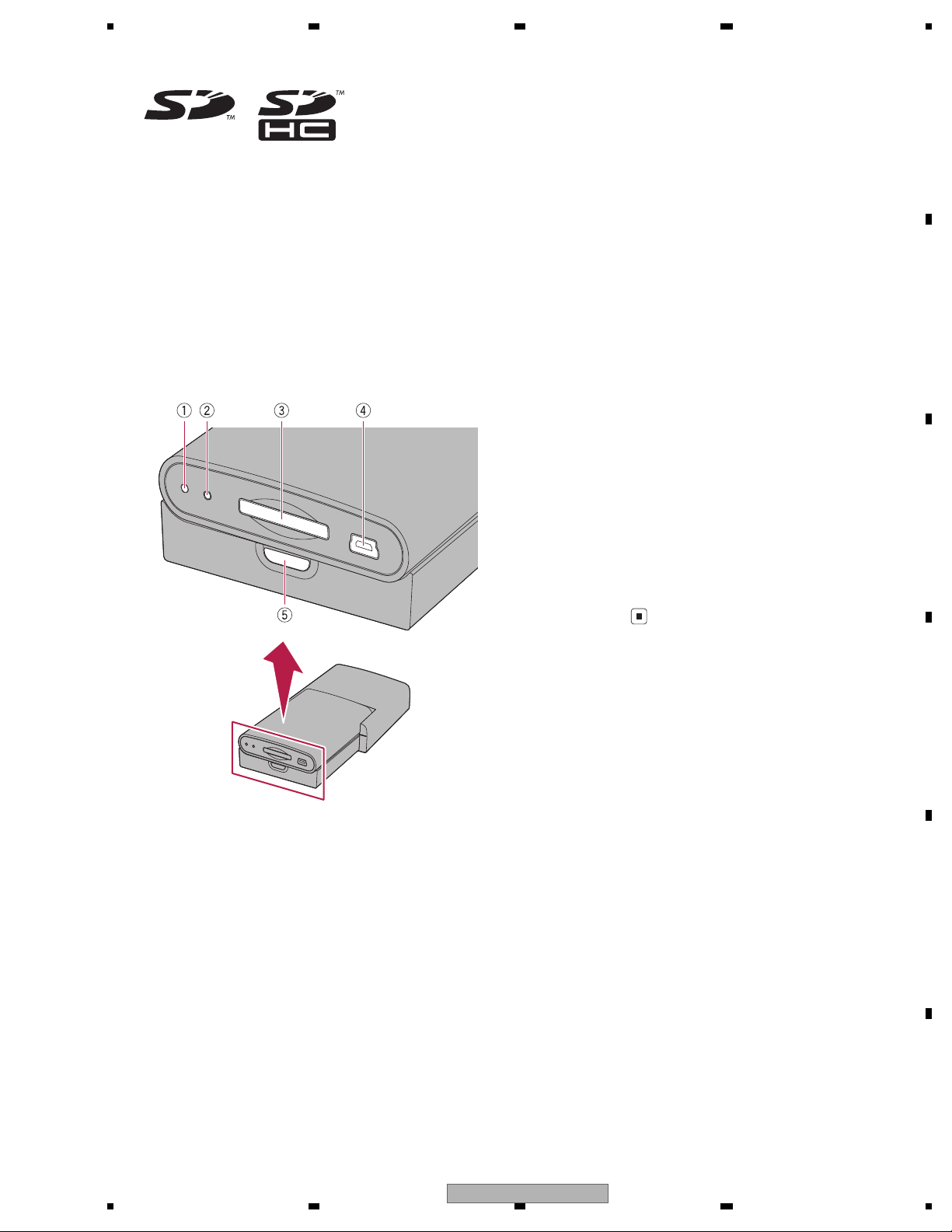
1 Power indicator
2 RESET button
3 SD card slot
4 USB port (Mini-B)
Use to connect with your PC.
5 Detach button
Press to remove the detachable device from
the base unit.
2.2 DISC/CONTENT FORMAT
2.3 PANEL FACILITIES
AVIC-U220/XZUC
7
Page 8
1234
1234
C
D
F
A
B
E
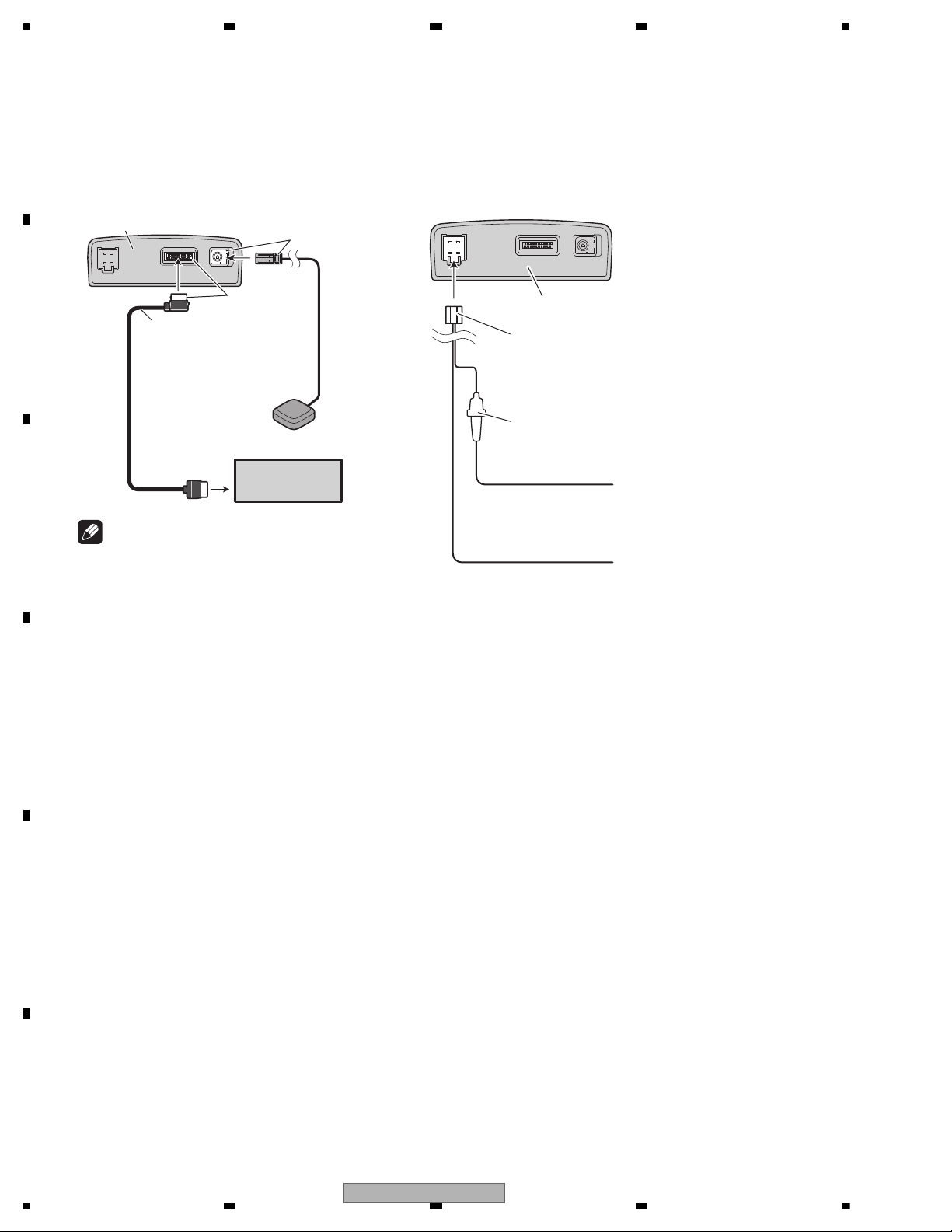
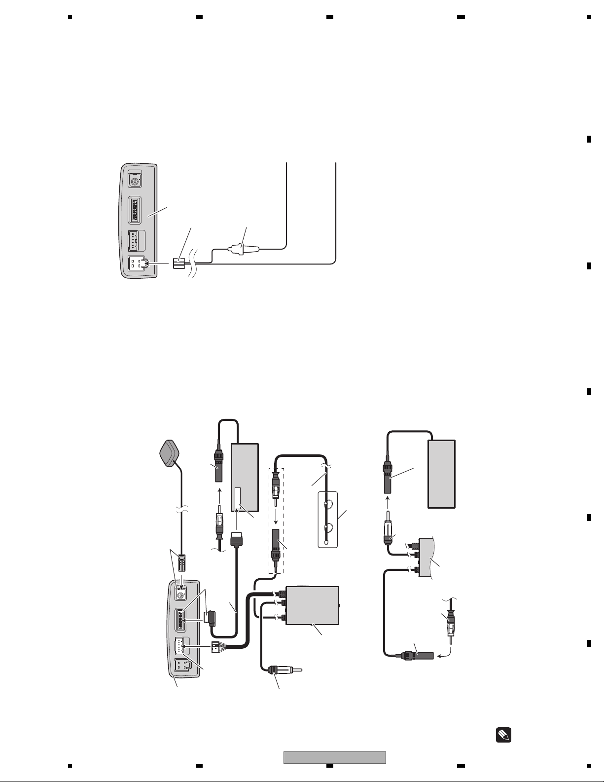
2.4 CONNECTION DIAGRAM
Connecting the system
26-pin cable
(supplied)
3.55 m
(11 ft. 8 in.)
2 m (6 ft. 7 in.)
GPS antenna
Green
Yellow
Base unit
AV receiver
Note
The terminal form of the 26-pin cable may differ
depending on the terminal type of the AV receiver.
For details of connection, refer to the installation
manual supplied with the AV receiver.
Connecting the power cord
Yellow
To terminal always supplied
with power regardless of
ignition switch position.
Black (ground)
To vehicle (metal) body.
Power cord
Base unit
Fuse holder
- UC, EW5, CS
8
AVIC-U220/XZUC
Page 9
5678
56
7
8
C
D
F
A
B
E
Connecting the system
We recommend connecting the supplied external aerial. Connect the aerial plug of your vehicle to the AV receiver di-
rectly (Fig. 1).
If you do not use the supplied external aerial in order to split radio signal between this product and the built-in tuner of
the AV receiver (Fig. 2), the radio sensitivity of the AV receiver may decrease.
26-pin cable (supplied)
3.55 m
2 m
GPS aerial
Green
Yellow
Base unit
RDS-TMC tuner
(supplied)
Not used.
Expansion port
30 cm
1 m
30 cm
AV receiver
RGB input
Aerial jack of AV receiver
External aerial (supplied)
Aerial jack
Vehicle aerial
For more details about the wiring.
(Fig. 1)
RDS-TMC tuner
AV receiver
A
erial jack of AV receiver
Vehicle aerial
Aerial jack
Aerial plug
(Fig. 2)
Note
The terminal form of the 26-pin cable may differ
depending on the terminal type of the AV receiver.
For details of connection, refer to the installation
manual supplied with the AV receiver.
Connecting the power cord
Yellow
To terminal always supplied
with power regardless of
ignition switch position.
Black (earth)
To vehicle (metal) body.
Power cord
Base unit
Fuse holder
- EU5, AU
AVIC-U220/XZUC
9
Page 10
1234
1234
C
D
F
A
B
E
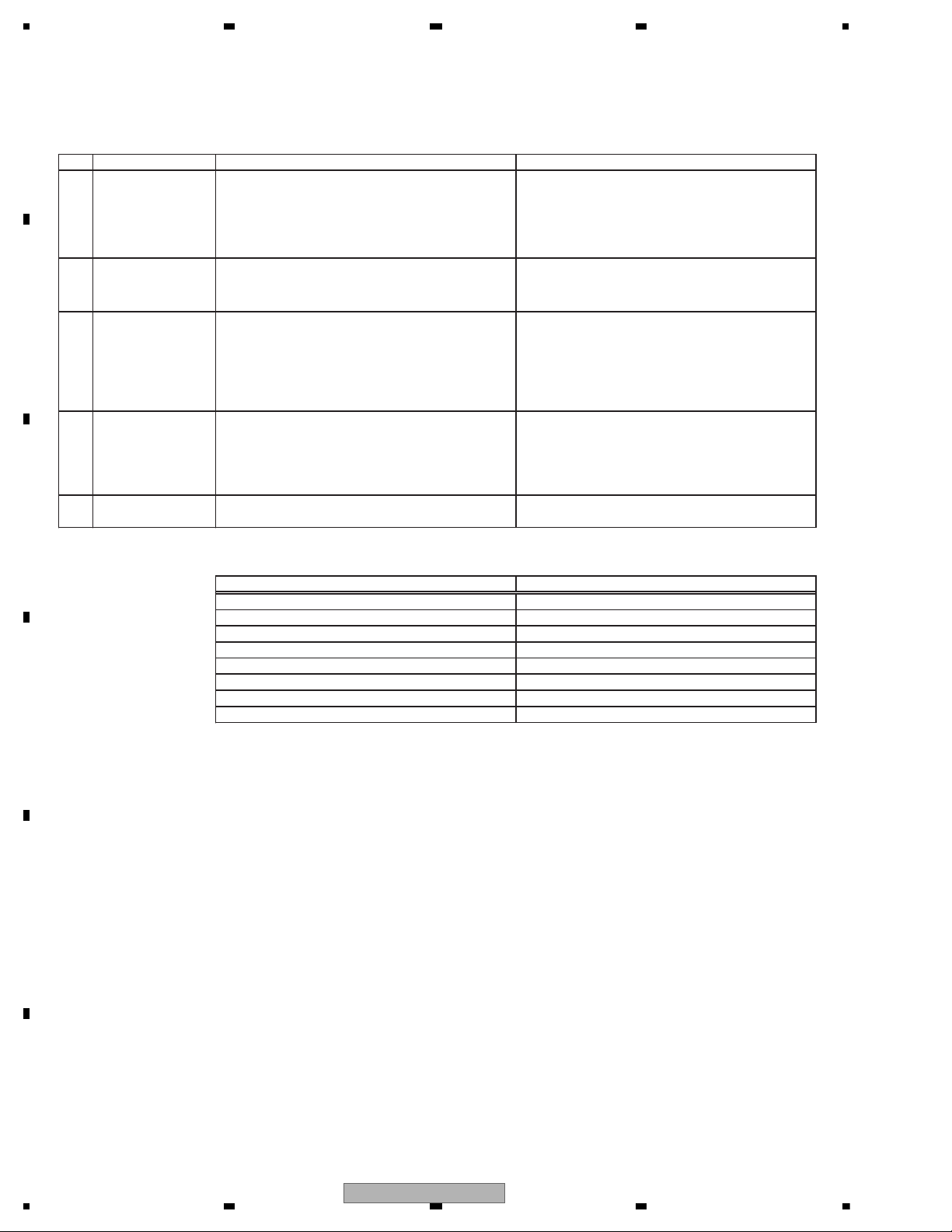
3. BASIC ITEMS FOR SERVICE
To keep the product quality after servicing, please confirm following check points.
No. Procedures Item to be confirmed
1
Confirm whether the customer complain has
been solved.
If the customer complain occurs with the
specific media, use it for the operation check.
The customer complain must not be reappeared.
Display, video, audio and operations must be
normal.
2 GPS positioning Connect GPS antenna to the product, and
check whether the current location is correct.
Current location must be correct.
Display and operations must be normal.
3 Map display
Touch-panel
operation
Remote-control
operation
Check functions of map scale change and map
scroll.
Display and operations must be normal.
4 Delete data added during the operating check.
Check whether no media (CD etc.) is inside the
product.
Make sure to delete data added during the
operating check.
The media used for the operating check must
be ejected.
5 Appearance check No scratches or dirt on its appearance after
receiving it for service.
See the table below for the items to be checked regarding video and audio:
Item to be checked regarding video Item to be checked regarding audio
Block-noise Distortion
Horizontal noise Noise
Dot noise Volume too low
Disturbed image (video jumpiness) Volume too high
Too dark Volume fluctuating
Too bright Sound interrupted
Mottled color
3.1 CHECK POINTS AFTER SERVICING
10
AVIC-U220/XZUC
Page 11

5678
56
7
8
C
D
F
A
B
E
AVIC-U220/XZUC
11
Page 12

1234
1234
C
D
F
A
B
E
4. BLOCK DIAGRAM
guide on signal
TV on Signal(AVH detects navi connection.)
CSYNC C
3.3Vp-p 0.
(w
M
I2C
Guide Signal
NAND FLASH
2GB/4GB
SOC
Samsung 2450
400MHz
SDRAM
64MB+64MB
SD Card Slot
CPLD
Battery
Charger IC
System
Power_IN
Mini-B USB
Connector
Reset Button
SDRAM Address Bus
SDRAM Data Bus
32-bit Bus
SD Contrpl
/Data Bus
Misc. Logic
Client USB2.0
XTAL
32.768KHz
XTAL
12MHz
XTAL
12MHz
RGB Digital 6-bit
Video
Decoder
V/H SYNC DCLK
Audio Codec
RGB Analog
Level Shift
u-COM TX/RX
TMC TX/RX
GPS TX/RX
NAVI UNIT
I2S
SD CN
mini USB CN
Deta
NAND Flash Bus
8bit Data BUS
4.1 BLOCK DIAGRAM
12
AVIC-U220/XZUC
Page 13

5678
56
7
8
C
D
F
A
B
E
CSYNC
0.3Vp-p
(with AVH)
Main 5V
Level Shift
u-COM TX/RX
TMC TX/RX
GPS TX/RX
CN
DC/DC
Converter
CN
CN
To TMC Unit
To AVH Unit
Power in(BUP)
CRADLE UNIT
BUP
GPS Module
other pwr
RTC pwr
Reg
ASENB
CN
GPS CN
Detach CN
AVIC-U220/XZUC
13
Page 14

1234
1234
C
D
F
A
B
E
5. DIAGNOSIS
Flow chart for Start / Navi Trouble Shooting
Note) Please refer to “Measure point” page, when you check the signal.
This model
connect to AVH.
AVH can change to
Navi source
Trouble in Navi unit
Does LED of
this model
light?
Is Battery connected
to Navi board?
Trouble in Cradle unit
After replacing the
Cradle unit to new one,
can AVH change the
source to Navi ?
Trouble in RGB cable
Is BUP in cradle unit
OK?
Trouble in power cable
or fuse
Is ASENB_OUT
in cradle unit
OK?
Trouble in detach
connector
Trouble in Cradle unit
Trouble in Battery
connector
After replacing the
Navi unit to new one,
can AVH change the
source to Navi ?
Flow Chart for BEEP, GUIDE Trouble Shooting
Is Sounds outputted
from front Speaker?
BEEP, GUIDE
After replacing the
Cradle unit to new one,
is sounds outputted
from the SP?
Trouble in Cradle unit
Trouble in Navi unit
Trouble in AVH unit
No
No
No
No
No
No
No
No
No
No
No
Yes
YesYes
Yes
Yes
Yes Yes
YesNo Yes
Yes
LED(green) lighting condition
Main_5V is active
*BUP is hi and ASENB_IN (from AVH) is hi.
*Lighting mode is above one kind. (always lighting)
Is there
"Guide_audio_cradle"?
Is there
"Guide_audio_navi"?
Trouble in Navi unit
Trouble in detach
connector
After replacing the
RGB cable to new one,
is sounds outputted
from the SP?
5.1 DIAGNOSIS FLOWCHART
14
AVIC-U220/XZUC
Page 15

5678
56
7
8
C
D
F
A
B
E
Flow Chart for TMC Trouble Shooting (EU5/AU) Flow Chart for GPS Trouble Shooting
Can the product receive
TMC information?
No
No
No
Yes
No
Yes
Yes
No
No
No
Yes
No
No
Yes
Yes
Is electric wave in a
TMC TUNER JASO
connector?
Can the product receive
GPS?
Trouble in GPS anntena
Trouble in Cradle unit
Trouble in Navi unit
Trouble in TMC anntena
or TMC cable
Trouble in Cradle unit
Trouble in Navi unit
Trouble in TMC UNIT
Trouble in Cradle unit
Is TMC_BUP in
cradle unit OK?
Trouble in RGB cable
Is GPS_RF_IN OK?
When you change
TMC unit into new it.
Can the product receive
TMC information?
When you change
Cradle unit into new it.
Can the product receive
TMC information?
When you change
Navi unit into new it.
Can the product receive
TMC information?
When you change
Navi unit into new it.
Can the product receive
GPS?
When you change
Cradle unit into new it.
Can the product receive
GPS?
AVIC-U220/XZUC
15
Page 16

1234
1234
C
D
F
A
B
E
Measure point
GPS_RF_IN
TMC_BUP
BUP
1
32
2
31
2
1
3
4
4
3
31
32
Navi unit
Cradle unit
GND
Main_5V
Guide_audio_
cradle
25
ASENB_OUT
Cradle unit
Cradle unit
Navi unit
21
ASENB_IN
*It pass the navi unit from
"ASENB_OUT"
Guide_audio_
navi
16
AVIC-U220/XZUC
Page 17

5678
56
7
8
C
D
F
A
B
E
NAVI UNIT
CRADLE UNIT
SD Card slot connectorUSB connector
Power connector
TMC connector AVH connector
GPS connector
1 : NC
2 : BUP
3 : GND
4 : NC
42
31
1 : TMC BUP
2 : TMC ON
3 : TMC SNS
4 : PND TO TMC
5 : TMC TO PND
6 : GND
123456
1 : VIDEO R
2 : VIDEO G
3 : VIDEO B
4 : COMP SYNC
5 : AV GND
6 : NC
7 : NC
8 : NC
9 : ASENB
10 : NC
11 : NC
12 : NC
13 : AUDIO OUT+
14 : AUDIO OUT15 : NC
16 : NC
17 : NC
18 : NC
19 : DSEN_PND#
20 : TVON AVH
21 : GION#
22 : NC
23 : NC
24 : STON
25 : NTOS
26 : GND
252321191715131197531
2624222018161412108642
5.2 CONNECTOR FUNCTION DESCRIPTION
AVIC-U220/XZUC
17
Page 18

1234
1234
C
D
F
A
B
E
Navi unit Cradle unit
NAVI UNIT CRADLE UNIT
Interface connector B to B connector B to B connector Interface connector
USB connector Detach connector Detach connector Power connector AVH connector
No. Terminal name No. Terminal name No. Terminal name No. Terminal name No. Terminal name
1 VCC_USB_BUS 1 MAIN_5V 1 VCC_IN_5V 1 NA 1 VIDEO_R
2 TX_USBN- 2 MAIN_5V 2 VCC_IN_5V 2 BUP 2 VIDEO_G
3 RX_USBP+ 3 GUIDE_AUDIO_N 3 GUIDE_AUDIO_N 3 GND 3 VIDEO_B
4 USBID_CPLD 4 GUIDE_AUDIO 4 GUIDE_AUDIO 4 KMODE 4 COMP_SYNC
5 GND 5 TMC_TXD_MAIN_M 5 PNDTOTMC 5 AV_GND
6 A_GND 6 A_GND TMC connector 6 CVBS_OUT
Battery connector 7 TMC_RXD_MAIN_M 7 TMCTOPND No. Terminal name 7 AV_GND
No. Terminal name 8 DSEN_TMC_M# 8 DSEN_TMC_M# 1 TMCBUP 8 NA
1 NA 9 TMC_ON_M 9 TMC_ON_M 2 TMCON 9 ASENB
2 VBAT 10 GPS_RST_M# 10 GPS_RST_M# 3 TMCSNS# 10 AUDIO_L
3 VBAT 11 GPS_BS1_M 11 GPS_GS1_M 4 PNDTOTMC 11 AUDIO_R
4 CHG_V2P8 12 U_TXD_MAIN_M 12 U_TXD_MAIN_M 5 TMCTOPND 12 AGND
5 GND 13 GPS_EN_M 13 GPS_EN_M 6 GND 13 AUDIO_OUTPUT
14 U_RXD_MAIN_M 14 U_RXD_MAIN_M 14 AUDIO_OUTPUT_N
SD card slot connector 15 GPS_WAKE_M# 15 RF_WAKE_M# GPS connector 15 NA
No. Terminal name 16 TVON_M 16 TVON_M No. Terminal name 16 NA
1 SD0_DATA3 17 GND 17 GND 1 GND_GPS 17 NA
2 SD0_CMD 18 GION_M# 18 GION_M# 2 RFIN 18 NA
3 GND 19 DEN_PND_M# 19 DSEN_PND_M# 3 GND_GPS 19 DSEN_PND#
4 VCC_SD 20 GND 20 GND 20 TVON_AVH
5 SD0_CLK 21 ASENB_IN 21 ASENB_IN_M 21 GION#
6 GND 22 GPS_TXD_MAIN_M 22 GPS_TXD_MAIN_M 22 NA
7 SD0_DATA0 23 ACC_IN_M# 23 ACCON# 23 NA
8 SD0_DATA1 24 GPS_RXD_MAIN_M 24 GPS_RXD_MAIN_M 24 STON
9 SD0_DATA2 25 ASENB_OUT 25 ASENB_OUT 25 NTOS
10 COM 26 KMODE_MAIN_M 26 KMODE_CPU_M 26 GND
11 SD0_WP 27 AV_GND 27 AV_GND
12 SD0_DETECT 28 AV_GND 28 AV_GND
29 COMP_SYNC 29 COMP_SYNC
30 VIDEO_B 30 VIDEO_B
31 VIDEO_R 31 VIDEO_R
32 VIDEO_G 32 VIDEO_G
SD Card slot connector
Battery connector
USB connector
Detach connector
1
32
1
9
10
12
32
1
1
5
1
5
Power connector
1
6
1
26
1
3
43
21
Detach connector
TMC connectorAVH connector
GPS connector
18
AVIC-U220/XZUC
Page 19

5678
56
7
8
C
D
F
A
B
E
How to Use Test Mode
Startup procedures
1. Store the Test Mode folder on GGS1092 to the SD card root.
2. Download a ID file from the Service Site and copy it to the “Test Mode” folder on the SD card.
3. Insert the SD card in which the program is stored to the Navi unit and attach the Navi unit to the Cradle unit.
4. Turn ON the BUP and ACC of the main unit/AVH.
5. Press the Reset button on the Navi unit.
6. Press the Mode button on the AVH and go to the Navi source.
7. Test Mode will start up automatically.
* The touch panel may become inactive due to the state transition. Perform ACC_OFF/ON in that case.
Jig No : GGS1092
Test Mode menu
No. Test item Description of test
1 SD Test Not for service
2 System Load Not for service
3 Battery Displays the battery status, remaining quantity.
4 GPS Check Displays GPS reception status.
5 Flash ROM Read/Write/Compare test on Flash ROM
6 TMC TMC tuner error rate measurement
7 Voice Test Guide voice output test
8 Graphics Displays various test graphics.
9 Version Info Displays the version information of various SW.
10 USB Test Not for service
11 Port Test Displays Interface connection status.
6. SERVICE MODE
6.1 TEST MODE
AVIC-U220/XZUC
19
Page 20

1234
1234
C
D
F
A
B
E
Operation details
Battery
Displays the battery status.
GPS Check
GPS reception test is executed by “CN Value” command.
Battery Life Percent
ADC Value
Battery Flag
AC Line Status
AC Line Status
“Use Battery”: Indicates that it is operating only on battery.
“Use AC”: Indicates that it is operating on externally supplied power (power from
the main unit or PC).
Battery Flag
“CHARGING”: Indicates that the battery is being charged.
“HIGH”:It doesn't charge it. (Charge end or the power supply doesn't feed power.)
Battery Voltage Displays the voltage value for the battery.
ADC Value This is the AD conversion value of battery voltage.
Battery Life Percent This is the remaining battery quantity indicated as percent.
Battery Voltage
When it is unable to receive GPS
0 or N is indicated in red in the # and USE columns.
The values of DOP (precision) are not displayed.
20
AVIC-U220/XZUC
Page 21

5678
56
7
8
C
D
F
A
B
E
Flash ROM
Executes an operation test on Flash ROM
Folder Name Selects the partition to be tested.
Write files Writes the test file in an open area.
Read/verify files Reads the file written by Write files to compare it and check if it is correct.
Delete files Deletes the file written by Write files.
Format disk Formats the selected partition. (All files will be deleted. Caution is required.)
TMC
Measures the error rate for the external TMC tuner.
The reception frequency can be set up by operating “<” or “>.”
AVIC-U220/XZUC
21
Page 22

1234
1234
C
D
F
A
B
E
Voice Test
It is necessary to turn off the MUTE by Port Test menu before performing Voice Test.
Port Test
Click Port Test2
Click MUTE_ON (Turn off the MUTE)
Voice Test
Select a voice file.
Set DAC_Volume to "-4.5 dB", and then double-click the "Set" button.
Set MONO_out_Volume to "0 dB", and then double-click the "Set" button.
Double-click the Play (Loop) button.
22
AVIC-U220/XZUC
Page 23

5678
56
7
8
C
D
F
A
B
E
Graphics
Graphic test is executed by selecting the type of graphic with “Test” tab.
(Ex.) When center-marker is selected,
Version info
Click "Get Ver".
The versions of Bootloader (UBOOT), BSP and OS are displayed.
Click "APL".
The version of APL is displayed.
Click "MAP Ver".
The version of MAP is displayed.
AVIC-U220/XZUC
23
Page 24

1234
1234
C
D
F
A
B
E
Port Test
Executes the connection check with AVH.
For indications, please see the table below;
Parking brake signal
Port Test
“Hi” indication if Parking terminal of AVH is set to Low.
ILM Signal
“Hi” indication if ILM terminal of AVH is set to Hi.
Main Unit Get Connect
Main Unit Power Connect “Hi” indication if Main power supply of Cradle Unit is set to Hi
ACC status
Port Test 2
“Hi” indication if ACC terminal of AVH is set to Hi.
TMC status
“Hi” indication if TMC Unit is connected.
(Supported only for EU and AU model)
“Hi” indication if K-Mode terminal of this model is set to Low.
(Supported only for UC model)
K-Mode signal
24
AVIC-U220/XZUC
Page 25

5678
56
7
8
C
D
F
A
B
E
2
While the photograph shown is slightly different from this model in shape, the disassembly procedure is the same.
-
Removing the NAVI PCB (Fig.1, 2)
Fig.1
Remove the twelve hooks
in order of the number of the mark ( )
and then remove the Cover. (Fig.1)
* Case opener Jig (GGF1626) is available.
Remove the four screws. (Fig.1)
Fig.2
Fig.3
Fig.4
1
Remove the two screws
and then remove the NAVI PCB. (Fig.2)
- Removing the Cradle PCB (Fig.3, 4)
Remove the four screws. (Fig.3)
1
2
Remove the screw
and then remove the Cradle PCB. (Fig.4)
Cover
2
2
2
2
2
1
1
4
3
4
4
3
1
1
1
1
2
2
NAVI PCB
Remove the eleven hooks
in order of the number of the mark ( )
and then remove the Cover. (Fig.3)
Cover
Cradle PCB
1
1
2
3 4
2
3 4
5
5
5
2
1
1
1
1
7. DISASSEMBLY
AVIC-U220/XZUC
25
Page 26

1234
1234
C
D
F
A
B
E
The sponge (345172300100) must align line.
- How to assemble Rear Cover
26
AVIC-U220/XZUC
Page 27

5678
56
7
8
C
D
F
A
B
E
8. EACH SETTING AND ADJUSTMENT
There is not information to be shown in this chapter.
AVIC-U220/XZUC
27
Page 28

1234
1234
C
D
F
A
B
E
9. EXPLODED VIEWS AND PARTS LIST
N
OTES : Parts marked by " * " are generally unavailable because they are not in our Master Spare Parts List.
The > mark found on some component parts indicates the importance of the safety factor of the part.
Therefore, when replacing, be sure to use parts of identical designation.
9.1 PACKING
Screw adjacent to mark on the product are used for disassembly.
For the applying amount of lubricants or glue, follow the instructions in this manual.
(In the case of no amount instructions,apply as you think it appropriate.)
""
28
AVIC-U220/XZUC
Page 29

5678
56
7
8
C
D
F
A
B
E
(1) PACKING SECTION PARTS LIST
Mark
Mark No. Description Part No.
1 TF-CABLE ASSY POWER 422176700001
2 •••••
3 TF-CABLE ASSY RGB 422176700002
4 GPS Antenna Assy CXE3204
5 RDS-TMC Tuner See Contrast table (2)
6 TF-ANTENNA See Contrast table (2)
7 Cord Assy CDP1261
8
9 SCREW FOR INSTALLATION 452176700200
10 Lock Tie 344176700001
11 GIFT BOX See Contrast table (2)
12 INNER SOCK 227176700001
13 TF-DOCUMENT KIT See Contrast table (2)
14 IM CD-ROM See Contrast table (2)
VELCRO STRAP FOR INS
452176700100
No. Description Part No.
15-1 Quick Start Guide See Contrast table (2)
15-2 Quick Start Guide See Contrast table (2)
15-3 Quick Start Guide See Contrast table (2)
15-4 Quick Start Guide See Contrast table (2)
15-5 Quick Start Guide See Contrast table (2)
15-6 Quick Start Guide See Contrast table (2)
15-7 Important Information See Contrast table (2)
15-8 Installation Manual See Contrast table (2)
* 15-9 Warranty Card See Contrast table (2)
* 15-10 Registration Card See Contrast table (2)
15-11 Caution Card 561817670003
16 GND Sheet CZN8510
(2) CONTRAST TABLE
AVIC-U220/XZUC, AVIC-F220/XZEU5, AVIC-F220/XZUW5, AVIC-F220/XZAU and AVIC-F220/XZCS are constructed the same except for the following:
Mark No. Description
5 RDS-TMC Tuner Not used CXE2176 Not used CXE2176 Not used
6 TF-ANTENNA Not used 313002000624 Not used 313002000624 Not used
11 GIFT BOX 221176740001 221176740002 221176740004 221176740003 221176740005
13 TF-DOCUMENT KIT ••••• ••••• ••••• ••••• •••••
14 IM CD-ROM 565117670051 565117670052 565117670054 565117670053 565117670055
AVIC -U220
/XZUC
AVIC -F220
/XZEU5
AVIC -F220
/XZUW5
AVIC -F220
/XZAU
AVIC -F220
/XZCS
15-1 Quick Start Guide 561517670001 561517670003 561517670016 561517670020 561517670017
15-2 Quick Start Guide 561517670002 561517670004 561517670021 Not used Not used
15-3 Quick Start Guide Not used 561517670005 Not used Not used Not used
15-4 Quick Start Guide Not used 561517670018 Not used Not used Not used
15-5 Quick Start Guide Not used 561517670019 Not used Not used Not used
15-6 Quick Start Guide Not used 561517670022 Not used Not used Not used
15-7 Important Information 561517670006 561517670007 561517670009 561517670008 561517670010
15-8 Installation Manual 561517670011 561517670012 561517670014 561517670013 561517670015
* 15-9 Warranty Card 561817670001 561817670002 561817670002 Not used Not used
* 15-10 Registration Card 561817670004 Not used Not used Not used Not used
AVIC-U220/XZUC
29
Page 30

1234
1234
C
D
F
A
B
E
Owner's Manual,Installation Manual
Part No. Language
561517670001 English
561517670002 French
561517670006 English, French
561517670011 English, French
561517670003 English
561517670004 Spanish(Espanol)
561517670005 German
561517670018 French
561517670019 Italian
561517670022 Dutch
561517670007 English, Spanish(Espanol), German, French, Italian, Dutch
561517670012 English, Spanish(Espanol), German, French, Italian, Dutch
561517670016 English
561517670021 Russian
561517670009 English, Russian
561517670014 English, Russian
561517670020 English
561517670008 English
561517670013 English
561517670017 Portuguese(B)
561517670010 Portuguese(B)
561517670015 Portuguese(B)
CONTENTS OF CD-ROM (Operation Manual)
Part No. Language CD-ROM Part No
* CRB3368 English 565117670051
* CRB3369 French 565117670051
* CRB3370 English 565117670052
* CRB3371 Spanish(Espanol) 565117670052
* CRB3372 German 565117670052
* CRB3373 French 565117670052
* CRB3374 Italian 565117670052
* CRB3375 Dutch 565117670052
* CRB3377 English 565117670054
* CRB3378 Russian 565117670054
* CRB3376 English 565117670053
* CRB3379 Portuguese(B) 565117670055
All operation manuals are supplied in PDF files by the CD-ROM.
Regarding the availability of paper manual, contact Pioneer Service representative in your region.
30
AVIC-U220/XZUC
Page 31

5678
56
7
8
C
D
F
A
B
E
AVIC-U220/XZUC
31
Page 32

1234
1234
C
D
F
A
B
E
9.2 EXTERIOR
DETACHABLE DEVICE
BASE UNIT
32
AVIC-U220/XZUC
Page 33

5678
56
7
8
C
D
F
A
B
E
(1) EXTERIOR SECTION PARTS LIST
Mark
Mark No. Description Part No.
1 •••••
2 TF-FRONT COVER ASSY See Contrast table (2)
3 TF-NAVI BD ASSY See Contrast table (2)
4 TF-BATTERY PACK 338937010176
5 TF-ADHESIVE 346172300200
6 TF-MYLAR 346161000900
7 TF-SPONGE 345172300100
8 TF-SCREW M1.6L3 371101610324
9 TF-REAR COVER 344176700400
10 TF-SCREW M1.6L4 371101610412
11 WINDOWS CE LABEL 242160500101
12 •••••
13 •••••
14 TF-CAP FRONT COVER CRADLE 344176700600
15 TF-SPRING CAP CRADLE 344176700800
No. Description Part No.
16 TF-SPRING-SPRING CAP COVER 341176700100
17 TF-RAIL FRONT COVER CRADLE 344176700700
18 TF-HOOK BUTTON CRADLE 344176700900
19 TF-SPRING-HOOK BUTTON 341176700200
20 TF-CRADLE BD ASSY See Contrast table (2)
21 Connector(GPS) CKS5702
22 Connector(RGB) CKS4497
23 Connector(TMC) See Contrast table (2)
24 Fuse(3.15 A) CEK1259
>
25 TF-SCREW M1.6L3 371101610324
26 TF-REAR COVER CRADLE See Contrast table (2)
27 TF-SCREW M1.6L4 371101610412
28 •••••
29 Connector 331510032004
30 Connector 331510032003
(2) CONTRAST TABLE
AVIC-U220/XZUC, AVIC-F220/XZEU5, AVIC-F220/XZUW5, AVIC-F220/XZAU and AVIC-F220/XZCS are constructed the same except for the following:
Mark No. Description
2 TF-FRONT COVER
ASSY
3 TF-NAVI BD ASSY 441176700022 441176700023 441176700025 441176700024 441176700026
20 TF-CRADLE BD
ASSY
23 Connector(TMC) Not used CKS6115 Not used CKS6115 Not used
26 TF-REAR COVER
CRADLE
AVIC -U220
/XZUC
340176700200 340176700100 340176700100 340176700100 340176700100
411176700009 411176700011 411176700009 411176700011 411176700009
344176701200 344176701000 344176701200 344176701000 344176701200
AVIC -F220
/XZEU5
AVIC -F220
/XZUW5
AVIC -F220
/XZAU
AVIC -F220
/XZCS
AVIC-U220/XZUC
33
 Loading...