

Pilz PNOZ X7 Data Sheet
E-STOP relays, safety gate monitors
Up to Category 2, EN 954-1
PNOZ X7
Safety relay for monitoring E-STOP
pushbuttons.
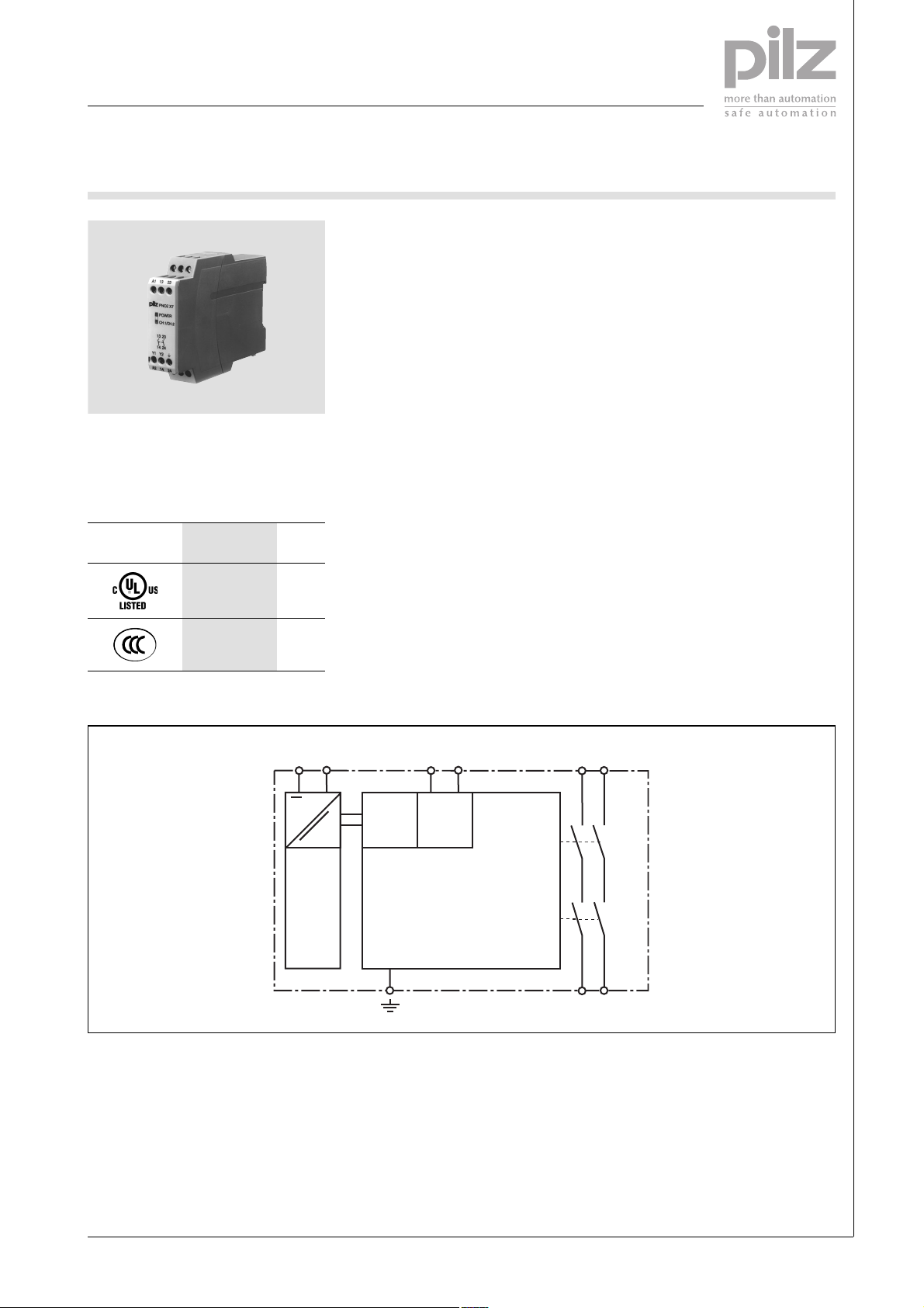
Approvals
PNOZ X7
Unit features
` Positive-guided relay outputs:
– 2 safety contacts (N/O), instanta-
neous
` Connection options for:
– E-STOP pushbutton
– Reset button
` LED indicator for:
– Switch status channel 1/2
– Supply voltage
` See order reference for unit types
Unit description
The safety relay meets the requirements of EN 60204-1 and IEC 602041 and may be used in applications with
` E-STOP pushbuttons
The safety relay is not suitable for noncontact barriers because
` a dynamic start is not possible
` the unit can be started during the
delay-on de-energisation time.
Safety features
The relay conforms to the following
safety criteria:
` The circuit is redundant with built-in
self-monitoring.
` The safety function remains effecti-
ve in the case of a component failure.
` The correct opening and closing of
the safety function relays is tested
automatically in each on-off cycle.
Block diagram
*Only when U
Galvanic isolation only when U
= 42 - 240 VAC
B
A1 A2 Y1 Y2
~
( )*
~
Input
Reset/
=
Power
( )*
= 42 – 240 VAC
B
13 23
Start
K1
K2
14 24
Pilz GmbH & Co. KG, Sichere Automation, Felix-Wankel-Straße 2, 73760 Ostfildern, Germany
Telephone: +49 711 3409-0, Telefax: +49 711 3409-133, E-Mail: pilz.gmbh@pilz.de
NSG-D-2-046-2010-01
E-STOP relays, safety gate monitors
Up to Category 2, EN 954-1
PNOZ X7
Function description
` Single-channel operation: no red-
undancy in the input circuit, earth
faults in the reset and input circuit
are detected.
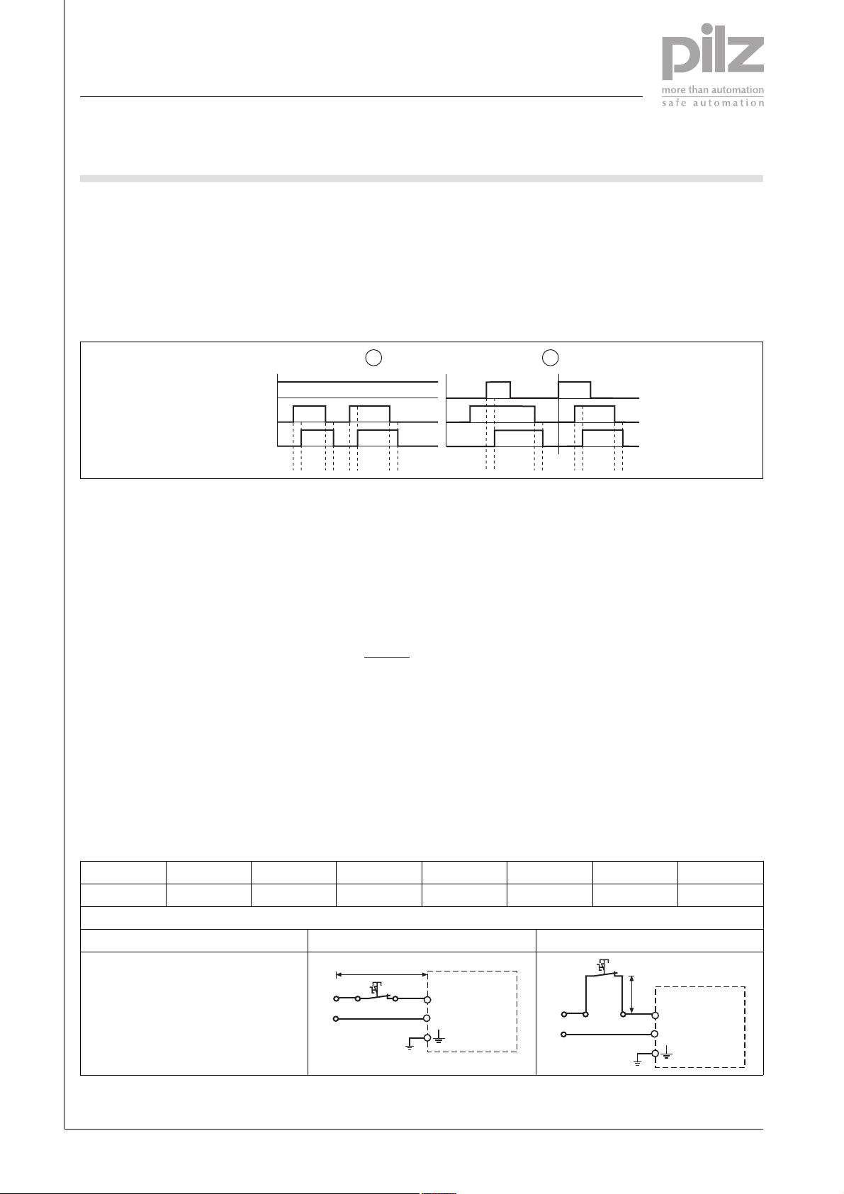
Timing diagram
Reset/Start
Power/Input
Output safe
Key
` Power: Supply voltage
` Reset/start: Reset circuit Y1-Y2
` Input: Input circuits A1
` Output safe: Safety contacts 13-14,
23-24
Wiring
` Automatic start: Unit is active once
the input circuit has been closed.
` Manual reset: Unit is active once
the input circuit is closed and then
the reset circuit is closed.
1 2
t1 t2 t1 t2 t2t1t1 t2
` c: Automatic reset
` d: Manual reset
` a: Input circuit closes before reset
circuit
` Increase in the number of available
contacts by connecting contact expander modules or external contactors/relays.
ab
` b: Reset circuit closes before input
circuit
: Switch-on delay
` t
1
` t2: Delay-on de-energisation
Please note:
` Information given in the “Technical
details” must be followed.
` Outputs 13-14, 23-24 are safety
contacts.
` To prevent contact welding, a fuse
should be connected before the
output contacts (see technical details).
` Calculation of the max. cable runs
in the input circuit:
l
max
` Use copper wire that can withstand
` Sufficient fuse protection must be
R
lmax
=
I
max
Rl / km
= max. overall cable resi-
R
lmax
stance (see technical details)
/km = cable resistance/km
R
l
60/75 °C.
provided on all output contacts with
capacitive and inductive loads.
Cable capacitance CL depends on the supply voltage U
B
PNOZ X7 AC: The cable runs depend
on the cable capacitance.
` Loop circuit, 1 phase: max. l
` Stub circuit: Cable capacitance C
and therefore the cable runs ls are
dependent on the supply voltage
U
B
UB [V] 42 48 110 115 120 230 240
C
[nF] 37.5 37.5 37.5 37.5 37.5 7.5 7.5
L
Loop circuit Stub circuit
Cable runs
U
N
l
r
B
PNOZ X7 AC
A1
A2
l
U
B
N
s
PNOZ X7 AC
A1
A2
= 1 km
r
L
Telephone: +49 711 3409-0, Telefax: +49 711 3409-133, E-Mail: pilz.gmbh@pilz.de
NSG-D-2-046-2010-01Pilz GmbH & Co. KG, Sichere Automation, Felix-Wankel-Straße 2, 73760 Ostfildern, Germany
-2
E-STOP relays, safety gate monitors
Up to Category 2, EN 954-1
PNOZ X7
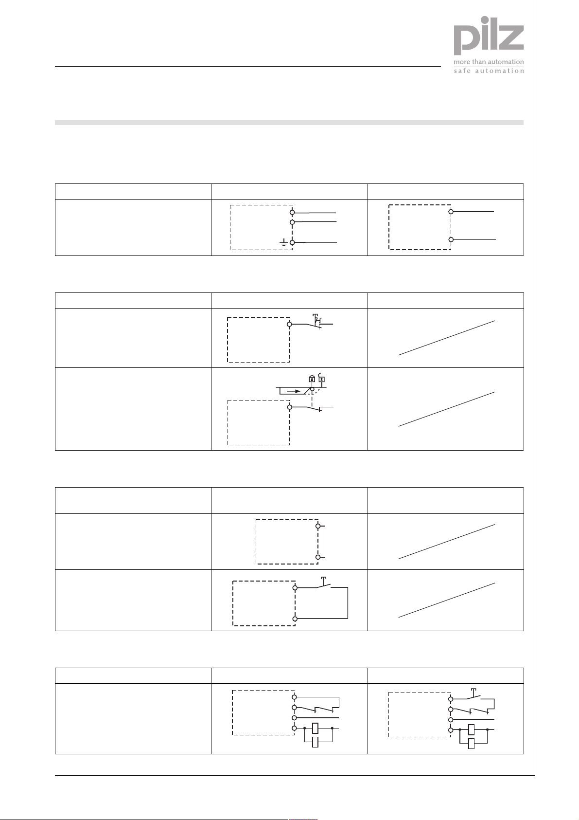
Preparing for operation
` Supply voltage
Supply voltage AC DC
A1
A2
L1
N
PE
` Input circuit
Input circuit Single-channel Dual-channel
E-STOP
without detection of shorts across
A1
S1
L+/L1
contacts
Safety gate
without detection of shorts across
contacts
S1
L+/L1A1
` Reset circuit
A1
A2
L+
L-
Reset circuit E-STOP wiring (single-channel)
Safety gate (single-channel)
Automatic reset
Y1
Y2
Manual reset
Y1
Y2
S3
E-STOP wiring (dual-channel)
Safety gate (dual-channel)
` Feedback loop
Feedback loop Automatic reset Manual reset
Contacts from external contactors
Y1
Y2
13 (23)
14 (24)
K5
K6
K5
K6
L1
N
Y1
Y2
13 (23)
14 (24)
K5
K6
K5
K6
S3
L1
N
Pilz GmbH & Co. KG, Sichere Automation, Felix-Wankel-Straße 2, 73760 Ostfildern, Germany
Telephone: +49 711 3409-0, Telefax: +49 711 3409-133, E-Mail: pilz.gmbh@pilz.de
NSG-D-2-046-2010-01
 Loading...