

Page 1

19486-6NL-04
PNOZ X5, PNOZ X5J, PNOZ X5.1
4
D Betriebsanleitung
4
GB Operating instructions
4
F Manuel d'utilisation
4 E Instrucciones de uso
4 I Istruzioni per l`uso
4 NL Gebruiksaanwijzing
Sicherheitsbestimmungen
• Das Gerät darf nur von Personen installiert
und in Betrieb genommen werden, die mit
dieser Betriebsanleitung und den geltenden Vorschriften über Arbeitssicherheit
und Unfallverhütung vertraut sind.
Beachten Sie die VDE- sowie die örtlichen
Vorschriften, insbesondere hinsichtlich
Schutzmaßnahmen.
• Beim Transport, der Lagerung und im
Betrieb die Bedingungen nach EN 600682-6 einhalten (s. technische Daten).
• Durch Öffnen des Gehäuses oder eigenmächtige Umbauten erlischt jegliche Gewährleistung.
• Montieren Sie das Gerät in einen Schaltschrank; Staub und Feuchtigkeit können
sonst zu Beeinträchtigungen der Funktionen führen.
• Sorgen Sie an allen Ausgangskontakten
bei kapazitiven und induktiven Lasten für
eine ausreichende Schutzbeschaltung.
Bestimmungsgemäße Verwendung
Das Sicherheitsschaltgerät dient dem
sicherheitsgerichteten Unterbrechen eines
Sicherheitsstromkreises. Das Sicherheitsschaltgerät erfüllt Forderungen der
EN 60947-5-1, EN 60204-1 und VDE 0113-1
und darf eingesetzt werden in Anwendungen
mit
• Not-Halt-Tastern
• Schutztüren
• Lichtschranken
Safety Regulations
• The unit may only be installed and
operated by personnel who are familiar
with both these instructions and the current
regulations for safety at work and accident
prevention. Follow VDE and local
regulations especially as regards
preventative measures.
•
Transport, storage and operating conditions
should all conform to EN 60068-2-6
• Any guarantee is void following opening of
the housing or unauthorised modifications.
• The unit should be panel mounted,
otherwise dampness or dust could lead to
function impairment.
• Adequate protection must be provided on
all output contacts especially with
capacitive and inductive loads.
.
Intended Applications
The safety relay provides a safety-related
interruption of a safety circuit. The safety
relay meets the requirements of EN 60947-51, EN 60204-1 and VDE 0113-1 and may be
used in applications with
• E-STOP pushbuttons
• Safety gates
• Light barriers
Conseils préliminaires
• La mise en oeuvre de l’appareil doit être
effectuée par une personne spécialisée en
installations électriques, en tenant compte
des prescriptions des différentes normes
applicables (NF, EN, VDE...) notamment
au niveau des risques encourus en cas de
défaillance de l’équipement électrique.
• Respecter les exigences de la norme
EN 60068-2-6 lors du transport, du
stockage et de l'utilisation de l'appareil.
• L’ouverture de l’appareil ou sa modification
annule automatiquement la garantie.
• L’appareil doit être monté dans une armoire; l’humidité et la poussière pouvant
entraîner des aléas de fonctionnement.
• Vérifiez que le pouvoir de coupure des
contacts de sortie est suffisant en cas de
circuits capacitifs ou inductifs.
Domaines d’utilisation
Le bloc logique de sécurité sert à interrompre
en toute sécurité un circuit de sécurité. Le
bloc logique de sécurité satisfait aux
exigences des normes EN 60947-5-1,
EN 60204-1 et VDE 0113-1 et peut être
utilisé dans des applications avec des
• poussoirs d'arrêt d'urgence
• protecteurs mobiles
• barrières immatérielles
Gerätebeschreibung
Das Sicherheitsschaltgerät ist in einem S-95Gehäuse untergebracht. Es stehen verschiedene Varianten für den Betrieb mit Gleichspannung und eine Variante für den Betrieb
mit Wechselspannung zur Verfügung.
Merkmale:
• Gerätetypen:
- PNOZ X5: Ein- oder zweikanalige
Ansteuerung
- PNOZ X5.1: Einkanalige Ansteuerung
mit interner Brücke zwischen S12-S22
ACHTUNG!
Die Betriebsart "manueller Start" ist
unzulässig für das sicherheitsgerichtete
Verhindern eines unerwarteten Anlaufs
nach EN 1037
- PNOZ X5J: wie PNOZ X5, aber
umgekehrte Polarität der Versorgungsspannung und geerdetes Pluspotenzial
• Relaisausgänge: 2 Sicherheitskontakte
(Schließer), zwangsgeführt
• Anschlussmöglichkeit für Not-Halt-Taster,
Schutztürgrenztaster und Starttaster
• Statusanzeige
• Überwachung externer Schütze möglich
• keine galvanische Trennung
Description
The Safety Relay is enclosed in a 22,5 mm
S-95 housing. There are different versions
available for AC operation and one for DC
operation.
Features:
• Unit Types:
- PNOZ X5: Single or dual-channel
operation
- PNOZ X5.1: Single-channel operation,
link S12-S22
CAUTION!
„Manual“ reset is not permitted as a
safety-related means of preventing
unexpected (unintended) start up in
accordance with EN 1037.
- PNOZ X5J: as the PNOZ X5, but the
supply voltage polarity and the earthed
+ potential are reversed
• Relay outputs: 2 safety contacts (N/O),
positive-guided.
• Connections for emergency stop button,
safety gate limit switch and reset button.
• Status indicators
• Feedback control loop for monitoring
external contactors/relays possible.
• No galvanic separation
Description de l’appareil
Inséré dans un boîtier S95, le bloc logique de
sécurité est disponible en différentes
versions pour les tensions d’alimentation
alternatives et une version en alimentation
continue (24 VDC).
Particularités :
• Types d’appareil:
- PNOZ X5: Commande par un ou deux
canaux
- PNOZ X5.1: Commande en monocanal
avec pont sur les bornes S12-S22
ATTENTION !
Le mode de fonctionnement
„Réarmement manuel“ n’est pas
adapté pour éviter de façon sûre un
démarrage intempestif d’après la norme
EN 1037.
- PNOZ X5J: comme PNOZ X5, mais
polarité inversée sur alimentation et
mise à la masse du plus.
• Sorties disponibles : 2 contacts à
fermeture de sécurité
• Bornes de raccordement pour poussoirs
AU, détecteurs de position et poussoir de
validation
• LEDs de visualisation
• Auto-contrôle des contacteurs externes
possible
• pas d'isolation galvanique
- 1 -
Page 2
Das Schaltgerät erfüllt folgende Sicherheitsanforderungen:
• Schaltung ist redundant mit Selbstüberwachung aufgebaut
• Sicherheitseinrichtung bleibt auch bei Ausfall eines Bauteils wirksam.
• Bei jedem Ein-Aus-Zyklus der Maschine
wird automatisch überprüft, ob die Relais
der Sicherheitseinrichtung richtig öffnen und
schließen.
The relay complies with the following safety
requirements:
• The circuit is redundant with built-in selfmonitoring
• The safety function remains effective in the
case of a component failure.
• The correct opening and closing of the
safety function relays is tested
automatically in each on-off cycle.
Le relais répond aux exigences suivantes :
• conception redondante avec autosurveillance
• sécurité garantie même en cas de
défaillance d’un composant
• test cyclique (ouverture/fermeture des
relais internes) à chaque cycle Marche/
Arrêt de la machine
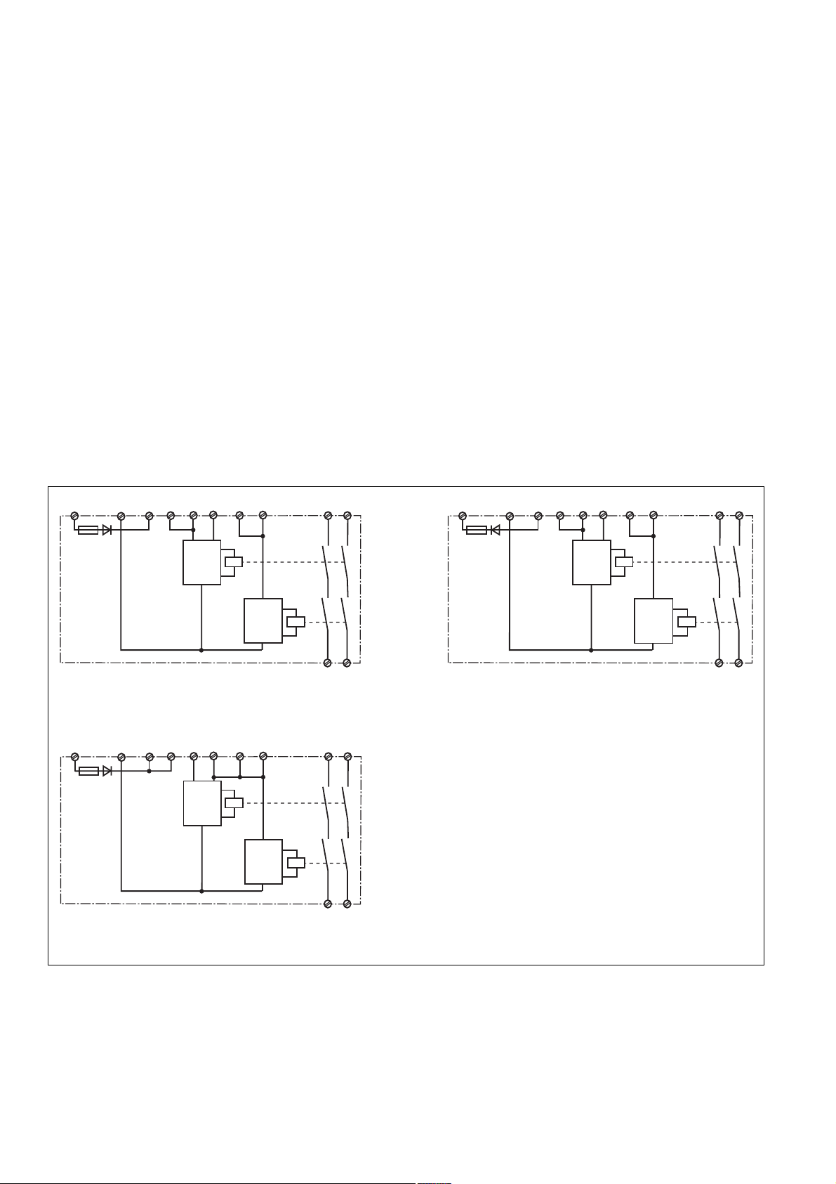
Funktionsbeschreibung
Das Schaltgerät dient dem sicherheitsgerichteten Unterbrechen eines Sicherheitsstromkreises. Nach Anlegen der
Versorgungsspannung leuchtet die LED
"POWER". Das Gerät ist betriebsbereit, wenn
der Startkreis S33-S34 geschlossen ist.
• Eingangskreis geschlossen (z. B. Not-HaltTaster nicht betätigt):
Relais K1 und K2 gehen in Wirkstellung und
halten sich selbst. Die Statusanzeigen für
"CH.1" und "CH.2" leuchten. Die Sicherheitskontakte 13-14/23-24 sind geschlossen.
• Eingangskreis wird geöffnet (z. B. Not-HaltTaster betätigt):
Relais K1 und K2 fallen in die Ruhestellung
zurück. Die Statusanzeige für "CH.1" und
"CH.2" erlischt. Die Sicherheitskontakte 1314/23-24 werden redundant geöffnet.
UB
A1 (L+) A2 (L-)
S11
S22 S12
Start
Unit
S34
S12S33
K1
Function Description
The relay provides a safety-oriented
interruption of a safety circuit. When the
operating voltage is supplied the LED
"POWER" is illuminated. The unit is ready
for operation, when the reset circuit S33-S34
is closed.
• Input circuit closed (e.g. the emergency
stop button is not pressed):
Relays K1and K2 energise and retain
themselves. The status indicators for
"CH.1" and "CH.2" illuminate. The safety
contacts (13-14/23-24) are closed.
• Input circuit is opened (e.g. emergency
stop button is operated)
Relays K1 and K2 de-energise. The
status indicators for "CH.1" and "CH.2" go
out. The safety contacts (13-14/23-24) will
be opened (redundant).
U
B
13
23
A1 (L-) A2 (L+)
Description du fonctionnement
Le relais assure de façon sure, l’ouverture
d’un circuit de sécurité. A la mise sous
tension du relais (A1-A2), la LED "POWER"
s'allume. Le relais est activé si le circuit de
réarmement S33-S34 est fermé.
• Circuits d'entrée fermés (poussoir AU non
actionné) :
Les relais K1 et K2 passent en position
travail et s'auto-maintiennent. Les LEDs
"CH.1" et CH.2" s'allument. Les contacts
de sécurité (13-14/23-24) sont fermés.
• Circuits d'entrée ouverts (poussoir AU
actionné) :
Les relais K1 et K2 retombent. Les LEDs
"CH.1" et "CH.2" s'éteingnent. Les
contacts de sécurité (13-14/23-24)
s'ouvrent.
K1
S12S33
13
S11
S22 S12
Start
Unit
S34
23
Start
Unit
Fig. 1: PNOZ X5 Innenschaltbild/Internal Wiring
Diagram/Schéma de principe
UB
A1 (L+) A2 (L-)
S11
S34
Start
Unit
S22 S12
K1
S12S33
Start
Unit
Fig. 3: PNOZ X5.1 Innenschaltbild/Internal Wiring
Diagram/Schéma de principe
Betriebsarten:
• Einkanaliger Betrieb: Eingangsbeschaltung
nach VDE 0113 und EN 60204; keine
Redundanz im Eingangskreis; Erdschlüsse
im Startkreis werden erkannt. Bei
Erdschlüssen im Not-Halt-Kreis löst die
Sicherung der Versorgungsspannung aus.
• Zweikanaliger Betrieb: Redundanter Eingangskreis, Erdschlüsse im Tasterkreis
werden erkannt.
• Automatischer Start: Gerät ist aktiv, sobald
Eingangskreis geschlossen ist.
K2
14
24
Fig. 2: PNOZ X5J Innenschaltbild/Internal Wiring
Diagram/Schéma de principe
13
23
K2
14
24
Operating Modes
• Single-channel operation: Input wiring
according to VDE 0113 and EN 60204, no
redundancy in the input circuit. Earth faults
are detected in the reset circuit. Earth
faults in the emergency stop circuit trigger
the internal electronic fuse.
• Dual-channel operation: Redundancy in
the input circuit. Earth faults in the
emergency stop circuit are detected.
• Automatic reset: Unit is active as soon as
the input circuit is closed.
- 2 -
Start
Unit
K2
14
24
Modes de fonctionnement
• Commande par 1 canal : conforme aux
prescriptions de la EN 60204, pas de
redondance dans le circuit d’entrée. La
mise à la terre du circuit de réarmement
est détectée. En cas de mise à la terre des
circuits d'entrée, le fusible électronique
déclenche.
• Commande par 2 canaux: circuit d’entrée
redondant, la mise à la terre est détectée.
• Réarmement automatique : le relais est
activé dès la fermeture des canaux
d’entrée.
Page 3

• Manueller Start: Gerät ist erst dann aktiv,
wenn ein Starttaster betätigt oder ein
Startkontakt geschlossen wird. Dadurch ist
ein automatischer Start des Schaltgeräts
nach Spannungsausfall und -wiederkehr
ausgeschlossen.
ACHTUNG!
Beim PNOZ X5.1 keine Sicherheitsfunktion.
• Kontaktvervielfachung und -verstärkung
durch Anschluss von externen Schützen
• Manual reset: Unit is only active when a
reset button has been pressed or reset
contact is closed. Therefore, automatic
reset is prevented following a loss/return of
supply voltage.
CAUTION!
There is no safety function on the PNOZ
X5.1
• Increase in the number of contacts
available contacts by connecting external
contactors / relays.
• Réarmement manuel : le relais n’est activé
qu’après une impulsion sur un poussoir de
validation. Un réarmement automatique du
relais après une coupure d’alimentation
est ainsi impossible.
ATTENTION !
PNOZ X5.1 : fonction non sécuritaire !
• Augmentation du nombre de contacts ou
du pouvoir de coupure par l’utilisation de
contacteurs externes.
Montage
Das Gerät muss in einen Schaltschrank
mit einer Schutzart von mindestens IP54
eingebaut werden. Zur Befestigung auf einer Normschiene hat das Gerät ein Rastelement auf der Rückseite. Sichern Sie das
Gerät bei Montage auf einer senkrechten
Tragschiene (35 mm) durch ein Halteelement wie z. B. Endhalter oder Endwinkel.
Inbetriebnahme
Beachten Sie bei der Inbetriebnahme:
• Vor die Ausgangskontakte eine
Sicherung (s. techn. Daten) schalten,
um das Verschweißen der Kontakte zu
verhindern.
• Erdschlüsse werden nur erkannt, wenn bei
allen Geräten die Verbindung zu A2 (L-)
bzw. A2 (L+) geerdet wird.
• Berechnung der max. Leitungslänge I
am Eingangs-, Start und Rückführkreis:
R
lmax
=
I
max
Rl / km
R
= max. Gesamtleitungs-
lmax
widerstand (s. technische Daten)
Rl /km = Leitungswiderstand/km
• Leitungsmaterial aus Kupferdraht mit einer
Temperaturbeständigkeit von 60/75 °C
verwenden.
• Das Anzugsdrehmoment der Schrauben
auf den Anschlussklemmen darf max.
0,6 Nm betragen.
• Sorgen Sie beim Anschluss von magnetisch wirkenden, auf Reedkontakten basierenden Näherungsschaltern dafür,
dass der max. Einschaltspitzenstrom (am
Eingangskreis) den Näherungsschalter
nicht überlastet.
• Angaben im Kapitel „Technische Daten“
unbedingt einhalten.
Ablauf:
• Versorgungsspannung:
Versorgungsspannung an Klemmen A1
und A2 anlegen
• Startkreis:
- Automatischer Start: S33-S34 brücken
- Manueller Start: Taster an S33-S34
anschließen
• Eingangskreis:
- Einkanalig:
Öffnerkontakt von Auslöseelement an
S11-S12 anschließen, S12-S22
brücken
- Zweikanalig: Öffnerkontakt von Auslöse-
element an S11-S12 und S11-S22
anschließen
•
Rückführkreis:
Öffnerkontakte der externen Schütze in
Reihe zu Startkreis S33-S34 anschließen
Die Sicherheitskontakte sind aktiviert (geschlossen). Die Statusanzeigen für "CH.1",
"CH.2" leuchten. Das Gerät ist betriebsbereit.
Wird der Eingangskreis geöffnet, öffnen die
Sicherheitskontakte 13-14/23-24. Die
Statusanzeige erlischt.
max
Installation
The unit must be installed in a control
cabinet with a minimum protection type of
IP54. The unit has a notch on the back for
DIN rail attachment. If you are installing the
unit on to a vertical DIN rail (35 mm) ensure
that it is mounted securely by using a
retaining bracket or an end angle.
Operation
Please note for operation:
• To prevent contact welding, a fuse (see
technical details) must be connected
before the output contacts.
• Earth faults are only detected on the units
if the connection to A2 (L-) or A2(L+) is
earthed.
• Calculating the max. cable runs I
input, reset and feedback circuit:
R
lmax
=
I
max
Rl / km
R
= max. overall cable
lmax
resistance (see Technical details)
Rl /km = cable resistance/km
• Use copper wiring that will withstand
60/75 °C
• Tighten terminals to 0.6 Nm.
• When connecting magnetically operated,
reed proximity switches, ensure that the
max. peak inrush current (on the input
circuit) does not overload the proximity
switch.
• Important details in the section "Technical
Data“ should be noted and adhered to.
To operate:
• Supply operating voltage:
Connect the operating voltage to terminals
A1 and A2
• Reset circuit:
- Automatic reset: Link S33-S34
- Manual reset: Connect button to S33-
S34
• Input circuit:
- Single-channel: Connect N/C contact
from safety switch to S11-S12, link S12S22.
- Dual-channel: Connect N/C contact from
safety switch (e.g. Emergency-Stop) to
S11-S12 and S11-S22.
• Feedback control loop:
Connect N/C contact from external
contactors / relays in series with reset
circuit S33-S34.
The safety contacts are activated (closed).
The status indicators "CH.1" and "CH.2" are
illuminated. The unit is ready for operation.
If the input circuit is opened, the safety
contacts 13-14/23-24 open. The status
indicator goes out.
max
at the
Montage
L’appareil doit être installé dans une armoire ayant un indice de protection IP54
minimum. Un élément d’encliquetage sur sa
face arrière permet de le monter sur rail
DIN. Lors du montage, bloquez l’appareil
sur un profilé support vertical (35 mm) à
l’aide d’un élément de maintien comme par
ex. un support ou une équerre terminale.
Mise en oeuvre
Remarques préliminaires :
• Raccordez un fusible (voir les caracté-
ristiques techniques) avant les contacts
de sortie afin d’éviter leur soudage.
• Mise à la terre uniquement détectée si
toutes les bornes A2 (L-) ou A2 (L+) de
tous les appareils sont reliées à la terre
• Calcul de la longueur maximale de conducteur I
de réarmement et la boucle de retour :
I
max
R
lmax
(voir les caractéristiques techniques)
Rl /km = résistance du câble/km
• Utiliser uniquement des fils de cablâge en
cuivre 60/75 °C.
• Le couple de serrage sur les bornes de
racordement ne doît pas dépasser
0,6 Nm.
• Lors du raccordement de détecteurs de
proximité magnétiques, basés sur des
contacts Reed, veuillez vous assurer que
le courant de crête max. à la mise sous
tension (sur le circuit d'entrée) ne
surcharge pas les détecteurs de
proximité.
• Respecter les données indiquées dans le
chap. „Caractéristiques techniques“.
Mise en oeuvre :
• Tension d’alimentation:
amener la tension d’alimentation sur A1
et A2
• Circuit de réarmement:
- Réarmement automatique: pontage des
bornes S33-S34
- Réarmement manuel : câblage d'un
poussoir sur S33-S34
• Circuits d’entrée:
- Commande par 1 canal : câblage du
contact à ouverture entre S11-S12,
pontage entre S12-S22
- Commande par 2 canaux: câblage des
contacts à ouverture entre S11-S12 et
S11-S22
• Boucle de retour:
Câblage en série des contacts à ouverture
externes dans le circuit de rèarmement
S33-S34
L
es contacts de sécurité se ferment. Les
LEDs "CH.1" et "CH.2" sont allumées.
L’appareil est prêt à fonctionner.
Si le circuit d’entrée est ouvert, les contacts
de sécurité retombent. Les LEDs
s’éteignent.
sur le circuit d’entrée, le circuit
max
R
lmax
=
Rl / km
= résistance max. totale du câble
- 3 -
Page 4
Wieder aktivieren
S11
S12 S22
S11
S34
S33
S3
BWS
24 V DC
• Eingangskreis schließen.
• Bei manuellem Start zusätzlich Taster
zwischen S33 und S34 betätigen.
Die Statusanzeigen leuchten wieder, die
Sicherheitskontakte sind geschlossen.
Reactivation
• Close the input circuit.
• For manual reset press the button between
S33-S34.
The status indicators light up again, the
safety contacts are closed.
Remise en route :
• fermer le circuit d’entrée
• en cas de réarmement manuel, appuyer sur
le poussoir de validation entre S33-S34.
Les affichages d'état s'allument à nouveau.
Les contacts de sécurité sont fermées.
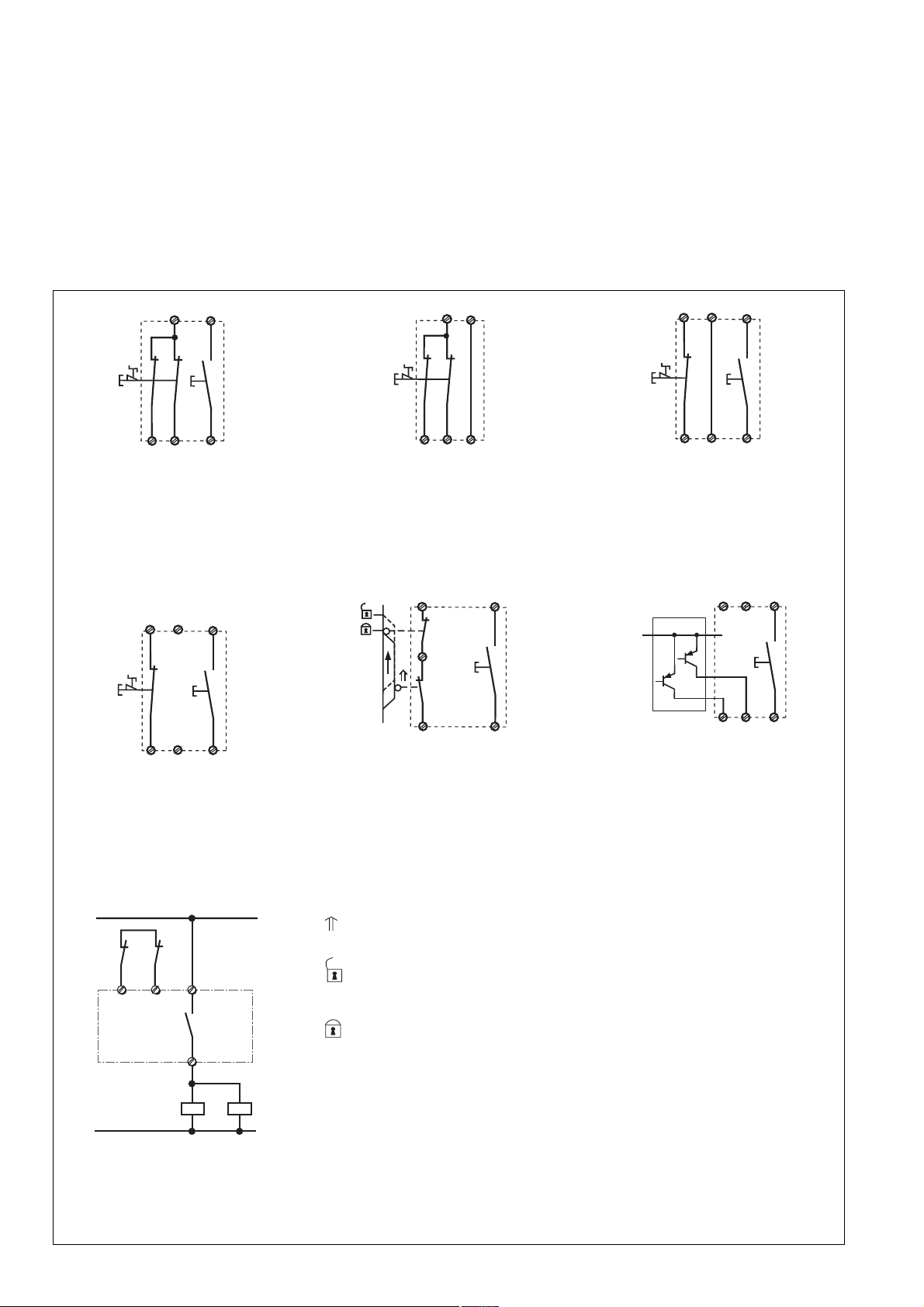
Anwendung
In Fig. 4 ... Fig. 10 sind Anschlussbeispiele
für Not-Halt-Beschaltung mit automatischem
und manuellem Start, Schutztüransteuerungen sowie Kontaktvervielfachung durch
externe Schütze.
S33
S11
S1
Fig. 4: nur bei PNOZ X5, PNOZ X5J: Eingangskreis zweikanalig, manueller Start/Only
PNOZ X5, PNOZ X5J: Dual-channel input
circuit, manual reset/PNOZ X5, PNOZ X5J
uniquement: Commande par 2 canaux,
réarmement manuel
S11
S12
S22
S12
S3
S34
S33
Application
In Fig. 4 ... Fig. 10 are connection examples
for emergency stop wiring with automatic and
manual reset, safety gate control and contact
expansion using external contactors / relays.
S11
S33
S1
S34
S22
S12
Fig. 5: nur bei PNOZ X5, PNOZ X5J: Eingangskreis zweikanalig, automat. Start/Only
PNOZ X5, PNOZ X5J: Dual-channel input
circuit, automatic reset/PNOZ X5, PNOZ X5J
uniquement:Commande par 2 canaux,
réarmement manuel
S12
S1S3S1
S33
Utilisation
Dans les figures 4 à 10 sont représentés
les différents cablages possibles: poussoirs
AU avec réarmement automatique et
surveillance du circuit de réarmement,
interrupteur de position et augmentation du
nombre des contacts par contacteurs
externes.
S11
S1
S12
Fig. 6: nur bei PNOZ X5, PNOZ X5J: Eingangskreis einkanalig, manueller Start/Only
PNOZ X5, PNOZ X5J:Single-channel input
circuit, manual reset/PNOZ X5, PNOZ X5J
uniquement: Commande par 1 canal,
réarmement manuel
S12
S22
S33
S3
S34
S1
S12
S22
S3
S34
Fig. 7: nur bei PNOZ X5.1: Eingangskreis
einkanalig, manueller Start/Only PNOZ X5.1:
Single-channel input circuit, manual reset/
PNOZ X5.1 uniquement: Commande par 1
canal, réarmement manuel
1L1
K4
K5
S34
S33
13
14
S11
S2
S22
S34
Fig. 8: Schutztürsteuerung zweikanalig,
manueller Start/Dual-channel safety gate
control, manual reset/Surveillance de
protecteur, commande par 2 canaux
betätigtes Element/Switch
activated/élément actionné
Tür nicht geschlossen/Gate open/
porte ouverte
Tür geschlossen/Gate closed/
porte fermée
Fig. 9: Lichtschrankensteuerung, zweikanalig, Querschlusserkennung durch BWS,
manueller Start/Dual-channel light curtain
control, short circuit detection via ESPE,
manual reset/Commande par 2 canaux par
barrage immatériel ,surveillance du poussoir
de validation, réarmement manuel
S1/S2: Not-Halt bzw. Schutztürschalter/
Emergency Stop Button, Safety Gate
Limit Switch/Poussoir AU, détecteurs de
position
S3: Starttaster/Reset button/Poussoir de
réarmement
K4 K5
1L2
Fig. 10: Anschlussbeispiel für externe
Schütze, einkanalig/Connection example for
external contactors/relays, single-channel/
Branchement contacteurs externes,
commande par 1 canal
- 4 -
Page 5

Fehler - Störungen
• Erdschluss
Die Versorgungsspannung bricht zusammen und die Sicherheitskontakte werden
über eine elektronische Sicherung
geöffnet. Nach Wegfall der Störungsursache und Abschalten der Versorgungsspannung für ca. 1 Minute ist das Gerät
wieder betriebsbereit.
• Fehlfunktionen der Kontakte: Bei verschweißten Kontakten ist nach Öffnen des
Eingangskreises keine neue Aktivierung
möglich.
• LED "Power" leuchtet nicht: Kurzschluss
oder fehlende Versorgungsspannung
Faults
• Earth fault
Supply voltage fails and the safety
contacts are opened via an electronic fuse.
Once the cause of the fault has been
removed and operating voltage is switched
off, the unit will be ready for operation after
approximately 1 minute.
• Contact failure: In the case of welded
contacts, no further activation is possible
after the input circuit has opened.
• LED "Power" is not illuminated if shortcircuit or the supply voltage is lost.
Erreurs - Défaillances
• Défaut de masse
La tension d’alimentation chute et les
contacts de sécurité sont ouverts par un
fusible électronique. Une fois la cause du
défaut éliminée et la tension d’alimentation
coupée, l’appareil est à nouveau prêt à
fonctionner après environ 1 minute.
• Défaut de fonctionnement des contacts de
sortie: en cas de soudage d’un contact lors
de l’ouverture du circuit d’entrée, un
nouvel réarmement est impossible.
• LED "Power" éteinte: tension
d'alimentation non présente ou courtcircuit interne.
Technische Daten
Elektrische Daten
Versorgungsspannung U
PNOZ X5, PNOZ X5.1
PNOZ X5J
Spannungstoleranz
Leistungsaufnahme bei U
PNOZ X5, PNOZ X5J, PNOZ X5.1
PNOZ X5
Frequenzbereich
Restwelligkeit
Spannung und Strom an
Eingangskreis
PNOZ X5 (UB: 24 V AC/DC),
PNOZ X5J, PNOZ X5.1
PNOZ X5 (UB: 12 V DC)
Start- und Rückführkreis
PNOZ X5 (UB: 24 V AC/DC),
PNOZ X5J
PNOZ X5.1
PNOZ X5 (UB: 12 V DC)
Anzahl der Ausgangskontakte
Sicherheitskontakte (S)
Gebrauchskategorie nach
EN 60947-4-1
EN 60947-5-1
(DC13: 6 Schaltspiele/Min.)
Konventioneller thermischer Strom
Kontaktmaterial
Kontaktabsicherung extern
EN 60947-5-1 (IK = 1 kA)
Schmelzsicherung flink
Schmelzsicherung träge
Sicherungsautomat
Charakteristik
Max. Gesamtleitungswiderstand R
Eingangskreise
PNOZ X5 (UB: 24 V AC/DC),
PNOZ X5J, PNOZ X5.1:
einkanalig DC
einkanalig AC
PNOZ X5 (UB: 24 V AC/DC), PNOZ
X5J:
zweikanalig ohne
Querschlusserkennung DC
zweikanalig ohne
Querschlusserkennung AC
PNOZ X5 (UB: 12 V DC):
einkanalig DC
zweikanalig ohne
Querschlusserkennung DC
Min. Eingangswiderstand im Ein-
schaltmoment
PNOZ X5 (UB: 24 V AC/DC),
PNOZ X5J, PNOZ X5.1
PNOZ X5 (UB: 12 V DC)
B
B
Technical Data
Electrical data
Supply Voltage U
PNOZ X5, PNOZ X5.1
PNOZ X5J
Voltage Tolerance
Power consumption at U
PNOZ X5, PNOZ X5J, PNOZ X5.1
PNOZ X5
Frequency Range
Residual Ripple
Voltage and Current at
Input circuit
PNOZ X5 (UB: 24 V AC/DC),
PNOZ X5J, PNOZ X5.1
PNOZ X5 (UB: 12 V DC)
Reset circuit and feedback loop
PNOZ X5 (UB: 24 V AC/DC),
PNOZ X5J
PNOZ X5.1
PNOZ X5 (UB: 12 V DC)
Number of output contacts
Safety contacts (N/O)
Utilization category in accordance with
EN 60947-4-1
EN 60947-5-1
(DC13: 6 cycles/min)
Conventional thermal current
Contact material
External contact fuse protection
EN 60947-5-1 (IK = 1 kA)
Blow-out fuse quick
Blow-out fuse slow
Safety cut-out
Characteristic
Max. overall cable resistance R
lmax
input circuits
PNOZ X5 (UB: 24 V AC/DC),
PNOZ X5J, PNOZ X5.1:
Single-channel DC
Single-channel AC
PNOZ X5 (UB: 24 V AC/DC), PNOZ
X5J:
Dual-channel without detection of
shorts across contacts DC
Dual-channel without detection of
shorts across contacts AC
PNOZ X5 (UB: 12 V DC):
Single-channel DC
Dual-channel without detection of
shorts across contacts DC
Min. input resistance in the starting
torque
PNOZ X5 (UB: 24 V AC/DC),
PNOZ X5J, PNOZ X5.1
PNOZ X5 (UB: 12 V DC)
B
B
Caractéristiques techniques
Données électriques
Tension d’alimentation U
PNOZ X5, PNOZ X5.1
PNOZ X5J
Plage de la tension d’alimentation
Consommation pour U
PNOZ X5, PNOZ X5J, PNOZ X5.1
PNOZ X5
Fréquence
Ondulation résiduelle
Tension et courant du
Circuit d’entrée
PNOZ X5 (UB: 24 V AC/DC),
PNOZ X5J, PNOZ X5.1
PNOZ X5 (UB: 12 V DC)
Circuit de réarmement et boucle
de retour
PNOZ X5 (UB: 24 V AC/DC),
PNOZ X5J
PNOZ X5.1
PNOZ X5 (UB: 12 V DC)
Nombre de contacts de sortie
contacts de sécurité (F)
Catégorie d’utilisation selon
EN 60947-4-1
EN 60947-5-1
(DC13: 6 manoeuvres/min)
Courant thermique conventionnel
Matériau contact
Protection des contacts externe
EN 60947-5-1 (IK = 1 kA)
Fusibles rapide
Fusibles normal
Dijoncteur
Caractéristique
Résistance de câblage totale max.
lmax
R
circuits d'entrée
lmax
PNOZ X5 (UB: 24 V AC/DC),
PNOZ X5J, PNOZ X5.1:
Commande par 1 canal DC
Commande par 1 canal AC
PNOZ X5 (UB: 24 V AC/DC), PNOZ
X5J:
Commande par 2 canaux sans
détection des court-circuits DC
Commande par 2 canaux sans
détection des court-circuits AC
PNOZ X5 (UB: 12 V DC):
Commande par 1 canal DC
Commande par 2 canaux sans
détection des court-circuits DC
Résistance d'entrée min. au moment
de la mise en marche
PNOZ X5 (UB: 24 V AC/DC),
PNOZ X5J, PNOZ X5.1
PNOZ X5 (UB: 12 V DC)
- 5 -
B
AC: 24 V, DC: 12 V, 24 V
AC: 24 V, DC: 24 V
24 V AC/DC: -15 ... +10 %
12 V DC: -20 ... + 20 %
B
24 V DC: 2 W, 24 V AC: 4 VA
12 V DC: 2,5 W
AC: 50 ... 60 Hz
24 V DC: 160 %,
12 V DC: 20 %
24 V DC/55 mA
24 V DC/70 mA
24 V DC/55 mA
24 V DC/25 mA
24 V DC/90 mA
2
AC1: 240 V/0,01 ... 6 A/
1500 VA
DC1: 24 V/0,01 ... 4 A/
100 W
AC15: 230 V/5 A;
DC13: 24 V/4 A
6 A
AgSnO2 + 0,2 µm Au
6 A
4 A
24 V AC/DC: 4 A
B/C
50 Ohm
150 Ohm
100 Ohm
250 Ohm
20 Ohm
35 Ohm
95 Ohm
24 Ohm
Page 6

Sicherheitstechnische Kenndaten
der Sicherheitsausgänge
PL nach EN ISO 13849-1
Kategorie nach EN 954-1
SIL CL nach EN IEC 62061
PFH nach EN IEC 62061
SIL nach IEC 61511
PFD nach IEC 61511
tM in Jahren
Zeiten
Einschaltverzögerung
Automatischer Start
PNOZ X5 (UB: 24 V AC/DC),
PNOZ X5J, PNOZ X5.1
PNOZ X5 (UB: 12 V DC)
Manueller Start
PNOZ X5 (UB: 24 V AC/DC),
PNOZ X5J, PNOZ X5.1
PNOZ X5 (UB: 12 V DC)
Rückfallverzögerung
bei Not-Halt
PNOZ X5 (UB: 24 V AC/DC),
PNOZ X5J, PNOZ X5.1
PNOZ X5 (UB: 12 V DC)
bei Netzausfall
PNOZ X5 (UB: 24 V AC/DC),
PNOZ X5J, PNOZ X5.1
PNOZ X5 (UB: 12 V DC)
Wiederbereitschaftszeit bei max.
Schaltfrequenz 1/s
nach Not-Halt
PNOZ X5 (UB: 24 V AC/DC),
PNOZ X5J, PNOZ X5.1
PNOZ X5 (UB: 12 V DC)
nach Netzausfall
PNOZ X5 (UB: 24 V AC/DC),
PNOZ X5J, PNOZ X5.1
PNOZ X5 (UB: 12 V DC)
Gleichzeitigkeit Kanal 1 und 2
Überbrückung bei Spannungs-
einbrüchen
PNOZ X5 (UB: 24 V AC/DC),
PNOZ X5J, PNOZ X5.1
PNOZ X5 (UB: 12 V DC)
Umweltdaten
EMV
Schwingungen nach EN 60068-2-6
Frequenz
Amplitude
Klimabeanspruchung
Luft- und Kriechstrecken nach
EN 60947-1
Verschmutzungsgrad
Bemessungsisloationsspannung
Bemessungsstoßspannungs-
festigkeit
Umgebungstemperatur
Lagertemperatur
Schutzart
Einbauraum (z. B. Schaltschrank)
Gehäuse
Klemmenbereich
Mechanische Daten
Gehäusematerial
Gehäuse
Front
Safety-related characteristics of
the safety outputs
PL in accordance with
EN ISO 13849-1
Category in accordance with
EN 954-1
SIL CL in accordance with
EN IEC 62061
PFH in accordance with
EN IEC 62061
SIL in accordance with IEC 61511
PFD in accordance with IEC 61511
tM in years
Times
Switch-on delay
Automatic reset
PNOZ X5 (UB: 24 V AC/DC),
PNOZ X5J, PNOZ X5.1
PNOZ X5 (UB: 12 V DC)
Manual reset
PNOZ X5 (UB: 24 V AC/DC),
PNOZ X5J, PNOZ X5.1
PNOZ X5 (UB: 12 V DC)
Delay-on De-Energisation
at E-STOP
PNOZ X5 (UB: 24 V AC/DC),
PNOZ X5J, PNOZ X5.1
PNOZ X5 (UB: 12 V DC)
with power failure
PNOZ X5 (UB: 24 V AC/DC),
PNOZ X5J, PNOZ X5.1
PNOZ X5 (UB: 12 V DC)
Recovery time at max. switching
frequency 1/s
after E-STOP
PNOZ X5 (UB: 24 V AC/DC),
PNOZ X5J, PNOZ X5.1
PNOZ X5 (UB: 12 V DC)
after power failure
PNOZ X5 (UB: 24 V AC/DC),
PNOZ X5J, PNOZ X5.1
PNOZ X5 (UB: 12 V DC)
Simultaneity channel 1 and 2
Supply interruption before de-
energisation
PNOZ X5 (UB: 24 V AC/DC),
PNOZ X5J, PNOZ X5.1
PNOZ X5 (UB: 12 V DC)
Environmental data
EMC
Vibration to EN 60068-2-6
Frequency
Amplitude
Climate Suitability
Airgap Creepage in accordance with
EN 60947-1
Pollution degree
Rated insulation voltage
Rated impulse withstand voltage
Ambient temperature
Storage temperature
Protection type
Mounting (eg. panel)
Housing
Terminals
Mechanical data
Housing material
Housing
Front panel
Caractéristiques techniques de
sécurité des sorties de sécurité
PL selon EN ISO 13849-1
Catégorie selon EN 954-1
SIL CL selon EN IEC 62061
PFH selon EN IEC 62061
SIL selon IEC 61511
PFD selon IEC 61511
tM en années
Temporisations
Temps de réarmement
Réarmement automatique
PNOZ X5 (UB: 24 V AC/DC),
PNOZ X5J, PNOZ X5.1
PNOZ X5 (UB: 12 V DC)
Réarmement manuel
PNOZ X5 (UB: 24 V AC/DC),
PNOZ X5J, PNOZ X5.1
PNOZ X5 (UB: 12 V DC)
Temps de retombée
en cas d'arrêt d'urgence
PNOZ X5 (UB: 24 V AC/DC),
PNOZ X5J, PNOZ X5.1
PNOZ X5 (UB: 12 V DC)
en cas de coupure d'alimentation
PNOZ X5 (UB: 24 V AC/DC),
PNOZ X5J, PNOZ X5.1
PNOZ X5 (UB: 12 V DC)
Temps de remise en service en cas de
fréquence de commutation max. 1/s
arrêt d'urgence
PNOZ X5 (UB: 24 V AC/DC),
PNOZ X5J, PNOZ X5.1
PNOZ X5 (UB: 12 V DC)
après une coupure d'alimentation
PNOZ X5 (UB: 24 V AC/DC),
PNOZ X5J, PNOZ X5.1
PNOZ X5 (UB: 12 V DC)
Désynchronisme canal 1 et 2
Tenue aux micro-coupures
PNOZ X5 (UB: 24 V AC/DC),
PNOZ X5J, PNOZ X5.1
PNOZ X5 (UB: 12 V DC)
Données sur l'environnement
CEM
Vibrations selon EN 60068-2-6
Frequence
Amplitude
Conditions climatiques
Cheminement et claquage selon
EN 60947-1
Niveau d'encrassement
Tension assignée d'isolement
Tension assignée de tenue aux
chocs
Température d’utilisation
Température de stockage
Indice de protection
Lieu d'implantation (ex. armoire)
Boîtier
Bornes
Données mécaniques
Matériau du boîtier
Boîtier
Face avant
PL e (Cat. 4)
Cat. 4
SIL CL 3
2,31E-09
SIL 3
2,03E-06
20
typ. 115 ms, max. 180 ms
typ. 124 ms, max. 230 ms
typ. 40 ms, max. 180 ms
typ. 80 ms, max. 230 ms
typ.: 18 ms, max.: 30 ms
typ.: 12 ms, max.: 20 ms
typ.: 110 ms, max.: 160 ms
typ.: 20 ms, max.: 30 ms
50 ms
40 ms
200 ms
50 ms
∞
20 ms
10 ms
EN 60947-5-1,
EN 61000-6-2
10 ... 55 Hz
0,35 mm
EN 60068-2-78
2
250 V
4 kV
-10 ... + 55 °C
-40 ... +85 °C
IP54
IP40
IP20
PPO UL 94 V0
ABS UL 94 V0
- 6 -
Page 7

Querschnitt des Außenleiters
(Schraubklemmen)
1 Leiter, flexibel
2 Leiter gleichen Querschnitts, flexibel mit Aderendhülse, ohne
Kunststoffhülse
ohne Aderendhülse oder mit TWINAderendhülse
Anzugsdrehmoment für
Schraubklemmen
Abmessungen H x B x T
Einbaulage
Gewicht
Cable cross section
(screw terminals)
1 core, flexible
2 core, same cross section flexible
with crimp connectors, without
insulating sleeve
without crimp connectors or with
TWIN crimp connectors
Torque setting for screw terminals
Dimensions H x W x D
Fitting Position
Weight
Capacité de raccordement
(borniers à vis)
1 conducteur souple
2 conducteurs de même diamètre
souple avec embout, sans chapeau
plastique
souple sans embout ou avec
embout TWIN
Couple de serrage (borniers à vis)
Dimensions H x P x L
Position de travail
Poids
0,2 ... 4,0 mm2, 24 - 10 AWG
0,2 ... 2,5 mm2, 24 - 14 AWG
0,2 ... 2,5 mm2, 24 - 14 AWG
0,6 Nm
87 x 22,5 x 121 mm
beliebig/any/indifférente
190 g
Es gelten die 09/03 aktuellen Ausgaben der
Normen
The version of the standards current at
09/03 shall apply
Se référer à la version des normes en
vigeur au 09/03.
Bestelldaten/Order reference/Caractéristiques
Typ/
Type/
Type
PNOZ X5
PNOZ X5
PNOZ X5
(coated version)
PNOZ X5J
PNOZ X5.1
Merkmale/
Features/
Caractéristiques
24 V AC/DC
12 V DC
12 V DC
24 V DC
24 V DC
Klemmen/
Terminals/
Borniers
Schraubklemmen/screw terminals/borniers à vis
Schraubklemmen/screw terminals/borniers à vis
Schraubklemmen/screw terminals/borniers à vis
Schraubklemmen/screw terminals/borniers à vis
Schraubklemmen/screw terminals/borniers à vis
Bestell-Nr./
Order no./
Référence
774 325
774 326
774 327
774 323
774 324
Lebensdauer der Ausgangsrelais/Service Life of Output relays/Durée de vie des relais de sortie
PNOZ X 5: 12 V DC
10
DC13: 24 V
1
AC1: 230 V
DC1: 24 V
AC15: 230 V
Courant coupé (A)
Nennbetriebstrom (A)
Nominal operating current (A)
0.1
10 100 1000 10000
Nombre de manvres x 10
PNOZ X5, PNOZ X5J, PNOZ X5.1: 24 V DC, 24 V AC
10
AC15: 230 V
DC13: 24 V
1
Courant coupé (A)
Nennbetriebstrom (A)
Nominal operating current (A)
0.1
10 100 1000 10000
Nombre de manvres x 10
Schaltspielzahl x 10
Cycles x 10
Schaltspielzahl x 10
Cycles x 10
3
3
3
3
DC1: 24 V
AC1: 230 V
3
3
- 7 -
Page 8

Abmessungen in mm (")/Dimensions in mm (")/Dimensions en mm (")
122 (4.8")
75 (2.95")
87 (3.42")
EG-Konformitätserklärung:
Diese(s) Produkt(e) erfüllen die Anforderungen der Richtlinie 2006/42/EG über Maschinen des europäischen Parlaments und des
Rates.
Die vollständige EG-Konformitätserklärung
finden Sie im Internet unter www.pilz.com
Bevollmächtigter: Norbert Fröhlich,
Pilz GmbH & Co. KG, Felix-Wankel-Str. 2,
73760 Ostfildern, Deutschland
22,5
(0,89")
EC Declaration of Conformity:
This (these) product(s) comply with the
requirements of Directive 2006/42/EC of the
European Parliament and of the Council on
machinery.
The complete EC Declaration of Conformity
is available on the Internet at www.pilz.com
Authorised representative: Norbert Fröhlich,
Pilz GmbH & Co. KG, Felix-Wankel-Str. 2,
73760 Ostfildern, Germany
Déclaration de conformité CE :
Ce(s) produit(s) satisfait (satisfont) aux
exigences de la directive 2006/42/CE relative aux machines du Parlement Européen et
du Conseil.
Vous trouverez la déclaration de conformité
CE complète sur notre site internet
www.pilz.com
Représentant : Norbert Fröhlich,
Pilz GmbH & Co. KG, Felix-Wankel-Str. 2,
73760 Ostfildern, Allemagne
Technischer Support
+49 711 3409-444 +49 711 3409-444
...
In vielen Ländern sind wir durch
unsere Tochtergesellschaften und
Handelspartner vertreten.
Nähere Informationen entnehmen
Sie bitte unserer Homepage oder
nehmen Sie Kontakt mit unserem
Stammhaus auf.
Technical support
... ...
In many countries we are
represented by our subsidiaries
and sales partners.
Please refer to our Homepage
for further details or contact our
headquarters.
Assistance technique
+49 711 3409-444
Nos filiales et partenaires
commerciaux nous représentent
dans plusieurs pays.
Pour plus de renseignements,
consultez notre site internet ou
contactez notre maison mère.
- 8 -
www
www.pilz.com
Pilz GmbH & Co. KG
Felix-Wankel-Straße 2
73760 Ostfildern, Germany
Telephone: +49 711 3409-0
Telefax: +49 711 3409-133
E-Mail: pilz.gmbh@pilz.de
Originalbetriebsanleitung/Original instructions/Notice originale
19486-6NL-04, 2010-08 Printed in Germany
Page 9

19486-6NL-04
PNOZ X5, PNOZ X5J, PNOZ X5.1
4 E Instrucciones de uso
4 I Istruzioni per l`uso
4 NL Gebruiksaanwijzing
Prescripciones de seguridad
• El dispositivo debe ser instalado y puesto
en funcionamiento exclusivamente por
personas que estén familiarizadas
con estas instrucciones de uso y con las
prescripciones vigentes relativas a la
seguridad en el trabajo y a la prevención
de accidentes. Observar tanto las prescripciones VDE como las prescripciones
locales, especialmente en lo que se
refiere a las medidas de protección.
• Durante el transporte, el almacenaje y el
funcionamiento hay que atenerse a las
condiciones conforme a EN 60068-2-6
(ver datos técnicos). Una vez finalizado
su tiempo de vida útil, hay que eliminar el
dispositivo de forma apropiada.
• La garantía se pierde en caso de que se
abra la carcasa o se lleven a cabo remodelaciones por cuenta propia.
• Montar el dispositivo dentro de un
armario de distribución; en caso contrario
es posible que el polvo y la suciedad
puedan afectar el funcionamiento.
• Cuidar de que haya un conexionado de
seguridad suficiente en todos los contactos de salida con cargas capacitivas e
inductivas.
Campo de aplicación adecuado
El dispositivo sirve para la interrupción
orientada a la seguridad de un circuito de
corriente de seguridad. El dispositivo de
seguridad cumple los requisitos de las
normas EN 60947-5-1, EN 60204-1 y
VDE 0113-1 y puede utilizarse en
aplicaciones con
• pulsadores de parada de emergencia
• puertas protectoras
• barreras fotoéletricas
Norme di sicurezza
• Il dispositivo può venire installato e
messo in funzione solo da persone che
conoscono bene le presenti istruzioni per
l’uso e le disposizioni vigenti riguardo alla
sicurezza di lavoro e all’antinfortunistica.
Osservare le disposizioni della VDE
(Associazione tedesca degli Ingegneri)
nonché le norme locali, soprattutto per
quanto riguarda le misure preventive di
protezione.
• Durante il trasporto, l’immagazzinamento
e il funzionamento attenersi alle
condizioni prescritte dalla norma
EN 60068-2-6 (v. Dati tecnici). Al termine
della propria durata, smaltire il dispositivo
in conformità alle norme vigenti.
• Se viene aperta la custodia oppure se
vengono apportate delle modifiche in
proprio decade qualsiasi diritto di
garanzia.
• Montare il dispositivo in un armadio
elettrico; altrimenti la polvere e l’umidità
possono pregiudicare le funzioni.
• Preoccuparsi che tutti i contatti di uscita
sui carichi capacitivi e induttivi siano
dotati di un cablaggio protettivo
sufficiente.
Uso previsto
Il modulo di sicurezza consente
I'interruzione sicura di un circuito di
sicurezza. Il modulo di sicurezza risponde ai
requisiti secondo EN 60947-5-1, EN 602041 e VDE 0113-1 e può essere utilizzato in
applicazioni con
• pulsanti di arresto d'emergenza
• ripari mobili
• barriere fotoelletriche
Veiligheidsvoorschriften
• Het apparaat mag uitsluitend worden
geïnstalleerd en in bedrijf genomen door
personen die vertrouwd zijn met deze gebruiksaanwijzing en met de geldende
voorschriften op het gebied van
arbeidsveiligheid en ongevallenpreventie.
Neemt u de van toepassing zijnde
Europese richtlijnen en de plaatselijke
voorschriften in acht, in het bijzonder
m.b.t. veiligheidsregels.
• Neem bij transport, opslag en in bedrijf de
richtlijnen volgens EN 60068-2-6 in acht
(zie technische gegevens). Het apparaat
na afloop van zijn levensduur op de juiste
wijze verwijderen en opslaan.
• Het openen van de behuizing of het eigen-machtig aanpassen heeft verlies van
de garantie tot gevolg.
• Monteer het apparaat in een schakelkast.
Stof en vocht kunnen anders de werking
nadelig beïnvloeden.
• Zorg bij alle uitgangscontacten bij
capacitieve en inductieve belastingen
voor voldoende beschermbedrading.
Toegelaten applicaties
Het veiligheidsrelais dient om een
veiligheidscircuit veilig te onderbreken. Het
veiligheidsrelais voldoet aan de eisen van
EN 60947-5-1, EN 60204-1 en VDE 0113-1
en mag worden gebruikt in toepassingen
met
• noodstopknoppen
• hekken
• lichtschermen
Descripción del dispositivo
El dispositivo de seguridad está montado
dentro de una carcasa S-95. Existen diversas variantes disponibles para el funcionamiento con tensión continua y una variante
para el funcionamiento con tensión alterna.
Características:
• Tipos de dispositivo:
- PNOZ X5: Excitación monocanal o
bicanal
- PNOZ X5.1: Excitación monocanal con
puente interno entre S12-S22
¡ATENCIÓN!
El modo de servicio “rearme manual”
no está permitido para la evitación
orientada a la seguridad de un
arranque inesperado según EN 1037
- PNOZ X5J: Al igual que PNOZ X5,
pero con polaridad inversa de la
tensión de alimentación y potencial
positivo con puesta a tierra
• Salidas de relé: 2 contactos de seguridad
(contactos N.A.), con guía forzada
Descrizione
Il relè di sicurezza è inserito in un alloggiamento S-95. Per il funzionamento a corrente
continua sono disponibili diverse varianti ed
una variante per il funzionamento con corrente alternata.
Caratteristiche:
• Tipi di dispositivo:
- PNOZ X5: comando ad uno o due
canali
- PNOZ X5.1: comando ad un canale
con ponticello interno tra S12-S22
ATTENZIONE!
il “resettaggio manuale” non è consentito per impedire per ragioni di sicurez-
za un avvio non voluto secondo la norma EN 1037
- PNOZ X5J: come il PNOZ X5, ma con
polarità della tensione di alimentazione
e messa a terra del potenziale positivo
invertiti.
• Uscite relè: 2 contatti di uscita (contatto
NA), a guida positiva
- 9 -
Apparaatbeschrijving
Het veiligheidsrelais is ondergebracht in een
S-95-behuizing. Er zijn verschillende
varianten voor de werking met
gelijkspanning beschikbaar en één variant
voor de werking met wisselspanning.
Kenmerken:
• Apparaattypes:
- PNOZ X5: één- of tweekanalige
aansturing
- PNOZ X5.1: éénkanalige aansturing
met interne brug tussen S12-S22
ATTENTIE!
De bedrijfsmodus “handmatige start” is
niet toegestaan voor het veiligheidsgerelateerde verhinderen van een onverwachte aanloop volgens EN 1037
- PNOZ X5: zoals bij PNOZ X5, maar
met omgekeerde polariteit van de
voedingsspanning en geaarde
pluspotentiaal
• Relaisuitgangen: 2 veiligheidscontacten
(maakcontacten), mechanisch gedwongen
Page 10

• Posibilidad de conexión para pulsador de
parada de emergencia, final de carrera
de seguridad de puerta protectora y pulsador de rearme
• Indicación de estado
• Supervisión posible de contactores
externos
• Sin separación galvánica
El dispositivo cumple los requerimientos de
seguridad siguientes:
• El cableado está estructurado de modo
redundante con autosupervisión
• El equipo de seguridad permanece activo
aún cuando falle uno de los componentes.
• Con cada ciclo de conexión/desconexión
de la máquina se comprueba automáticamente si los relés del dispositivo de
seguridad abren y cierran correctamente.
• Possibilità di collegamento per pulsante di
arresto di emergenza, finecorsa riparo
mobile, pulsante di start, pedane
commutazione
• Indicatore di stato
• Possibile controllo di contattori esterni
• Nessun isolamento galvanico
Il relè risponde ai seguenti requisiti di sicurezza:
• Il circuito è strutturato in modo ridondante
con autocontrollo
• Il dispositivo di sicurezza funziona anche
in caso di guasto di un componente.
• Per ciascun ciclo di accensione/
spegnimento della macchina, viene
eseguita la verifica automatica della
corretta apertura e chiusura dei relè di
uscita del dispositivo di sicurezza.
• Aansluitmogelijkheid voor Noodstopknoppen, deurcontacten en startknoppen
• Statusweergave
• Bewaking van externe relais mogelijk
• Geen galvanische scheiding
Het relais voldoet aan de volgende
veiligheidseisen:
• De schakeling is redundant met
zelfcontrole opgebouwd
• Ook bij uitvallen van een component blijft
de veiligheidsschakeling functioneren.
• • Bij elke aan-uit-cyclus van de machine
wordt automatisch gecontroleerd, of de
relais van de veiligheidsschakeling op de
juiste wijze opengaan en sluiten.
Descripción de funciones
El dispositivo sirve para interrumpir por razones de seguridad un circuito de seguridad. El LED “POWER” se ilumina cuando
se aplica la tensión de alimentación. El
dispositivo se encuentra listo para el
servicio cuando el circuito de rearme S33S34 se encuentra cerrado.
• El circuito de entrada está cerrado (p.ej.
el pulsador de parada de emergencia no
ha sido accionado)
Los relés K1 y K2 se ponen en posición
de trabajo y se mantienen por sí mismos.
Se iluminan las indicaciones de estado
“CH.1” y “CH.2”. Los contactos de
seguridad 13-14/23-24 están cerrados.
• El circuito de entrada se abre (p.ej.
pulsador de parada de emergencia
accionado). K1 y K2 retornan a la
posición de reposo. Se apagan las indicaciones de estado de “CH.1” y “CH.2”.
Los contactos de seguridad 13-14/23-24
se abren de forma redundante.
U
B
A1 (L+) A2 (L-)
S11
S22 S12
Start
Unit
S34
K1
Descrizione del funzionamento
Il relè serve ad interrompere per motivi di sicurezza un circuito elettrico di sicurezza.
Dopo l’immissione della tensione di
alimentazione il LED “POWER” è acceso.
L’unità è pronta per il funzionamento,
quando il circuito di avvio S33-S34 è chiuso.
• Il circuito di entrata è chiuso (p. es.
pulsante di arresto di emergenza non
azionato)
I relè K1 e K2 si eccitano e si
automantengono. Gli indicatori di stato
per “CH” e “CH 2” si accendono. I contatti
di sicurezza 13-14/23-24 sono chiusi.
• Il circuito di entrata viene aperto (p. es.
pulsante di arresto di emergenza
azionato)
K1 e K2 si diseccitano. L’indicatore di
stato per “CH 1” e “CH 2” si spegne. I
contatti di sicurezza 13-14/23-24 vengono
aperti in modo ridondante.
S12S33
13
23
U
B
A1 (L-) A2 (L+)
Functiebeschrijving
Het relais PNOZ dient voor het veilig
onderbreken van een veiligheidsstroomcircuit. Na het inschakelen van de voedingsspanning brandt de LED “POWER“. Het
apparaat is bedrijfsklaar, wanneer het
startcircuit S33-S34 gesloten is.
• Ingangscircuit gesloten (bijv. Noodstopknop niet ingedrukt):
Relais K1 en K2 gaan naar de werkpositie
en blijven automatisch in deze positie.
De statusweergaven voor “CH.1” en
“CH.2” branden. De veilig-heidscontacten
13-14/23-24 zijn gesloten.
• Ingangscircuit wordt geopend (bijv. Noodstop-knop ingedrukt):
Relais K1 en K2 vallen in de ruststand af.
De statusweergave voor “CH.1” en “CH.2”
gaat uit. De veiligheidscontacten 13-14/
23-24 worden redundant geopend.
S11
S22 S12
Start
Unit
S34
S12S33
K1
13
23
Start
Unit
K2
Fig. 1: Esquema de conexiones internas PNOZ X5 /
Schema delle connessioni interne PNOZ X5 /
PNOZ X5 intern schakelschema
U
B
A1 (L+) A2 (L-)
S11
S34
Start
Unit
S22 S12
S12S33
K1
Start
Unit
K2
Fig. 3: Esquema de conexiones internas PNOZ X5.1
Schema delle connessioni interne PNOZ X5.1 /
PNOZ X5.1 intern schakelschema
Start
Unit
14
24
K2
14
24
Fig. 2: Esquema de conexiones internas PNOZ X5J /
Schema delle connessioni interne PNOZ X5 J /
PNOZ X5J intern schakelschema
13
23
14
24
- 10 -
Page 11

Modos de funcionamiento:
• Funcionamiento monocanal: Conexionado
de entrada según VDE 0113 y EN 60204,
sin redundancia en el circuito de entrada, se
detectan los contactos a tierra en el circuito
de rearme. En caso de contactos a tierra en
el circuito de parada de emergencia se dispara el fusible de la tensión de alimentación.
• Funcionamiento bicanal: Circuito de entrada
redundante, se detectan los defectos a
tierra en los contactos del pulsador.
• Rearme automático: El dispositivo se encuentra activo en cuanto que el circuito de
entrada se encuentra cerrado.
• Rearme manual: El dispositivo se encuentra
activo sólo después de que se haya accionado un pulsador de rearme o de que se
haya cerrado un contacto de rearme.
Mediante ello queda excluida la posibilidad
de un rearme automático del dispositivo
después de un corte y un restablecimiento
de la tensión.
¡ATENCIÓN!
Con PNOZ X5.1 ninguna función de seguridad.
• Multiplicación y refuerzo de contactos mediante la conexión de contactores externos.
Modalità di funzionamento:
• Funzionamento a canale singolo:
cablaggio di ingresso a norma VDE 0113
e EN 60204, nessuna ridondanza nel
circuito di entrata; vengono identificati i
guasti a terra nel circuito del pulsante. In
caso di dispersioni a terra nel circuito
dell’arresto di emergenza il fusibile della
tensione di alimentazione scatta.
• Funzionamento a due canali: circuito di
entrata ridondante, riconoscimento dispersioni a terra nel circuito del pulsante
di arresto di emergenza.
• Start automatico: l’unità è attiva non
appena il circuito di entrata viene chiuso.
• Start manuale: l’unità è attiva quando
viene attivato un pulsante di start o
quando viene chiuso un contatto di start.
In questo modo si esclude un avvio
automatico del relè dopo l’interruzione e
la ripresa dell’alimentazione di corrente.
ATTENZIONE!
Il PNOZ X5.1 non dispone della funzione
di sicurezza.
• Aumento del numero di contatti tramite
collegamento di contattori esterni
Bedrijfsmodi:
• Éénkanalig bedrijf: ingangsbedrading volgens VDE 0113 en EN 60204, geen
redundantie in het ingangscircuit; aardcontacten in het startcircuit worden
herkend. Bij aardcontacten in het
NOODSTOP-circuit wordt de beveiliging
van de voedingsspanning geactiveerd.
• Tweekanalig bedrijf: redundant in-gangscircuit, aardcontacten in het tastercircuit
worden herkend.
• Automatische start: het apparaat is actief,
zodra het ingangscircuit is gesloten.
• Handmatige start: Het apparaat is pas
actief, wanneer een startknop wordt
ingedrukt of een startcontact gesloten.
Daardoor is een automatische start van
het relais na uitval en terugkeer van de
spanning uitgesloten.
ATTENTIE!
Bij het PNOZ X5.1 geen veiligheids-
functie.
• Contactvermeerdering en -versterking
door aansluiting van externe relais
Montaje
El dispositivo de seguridad tiene que ser montado dentro de un armario de distribución con
un grado de protección de IP54 como mínimo.
El dispositivo dispone en su lado trasero de un
elemento para la fijación a una guía normalizada. Al montarlo en una guía portadora
vertical (35 mm) hay que asegurar el
dispositivo por medio de un elemento de
soporte, tal como un soporte o un ángulo final.
Puesta en marcha
Al poner en marcha hay que tener en cuenta:
• Conectar un fusible antes de los contac-
tos de salida (véanse datos técnicos)
con objeto de evitar la soldadura de los
contactos.
• Los contactos a tierra se detectan sólo si en
todos los dispositivos se pone a tierra la conexión con A2 (L-) o bien A2 (L+).
• Cálculo de la longitud máxima de línea I
en el circuito de entrada, de rearme y de
realimentación:
R
lmax
=
I
max
Rl / km
R
= resistencia máx. del total de la línea
Imáx
(véanse datos técnicos)
Rl /km = resistencia de línea/km
• Utilizar para las líneas material de alambre
de cobre con una resistencia a la temperatura de 60/75 °C.
• El par de apriete de los tornillos en los bornes de conexión puede ser de máx. 0,6
Nm.
• A la hora de conectar interruptores de
proximidad magnetosensibles basados en
contactos Reed, prestar atención a que el
pico máx. de corriente de conexión (en el
circuito de entrada) no sobrecargue el
interruptor de proximidad.
• Respetar sin falta las indicaciones del capítulo “Datos técnicos”.
Proceso
• Tensión de alimentación:
Aplicar la tensión de alimentación en los
bornes A1 y A2.
• Circuito de rearme:
- Rearme automático: Puentear S33-S34
- Rearme manual: Conectar pulsador a
S33-S34
máx
Montaggio
Il relè di sicurezza deve venire montato in
un armadio elettrico con un grado di
protezione di almeno IP54. Un dispositivo a
scatto sul retro del dispositivo serve per
fissare una guida DIN. Al montaggio fissare
il dispositivo su una guida verticale (35 mm)
a mezzo di supporti quali p. es. staffe di
fissaggio o angoli terminali.
Messa in funzione
Alla messa in funzione occorre considerare:
• Per evitare la saldatura dei contatti,
collegare un fusibile (v. Dati Tecnici)
prima dei contatti di uscita.
• Le dispersioni a terra vengono
riconosciute solo quando per tutte le unità
viene messo a terra il collegamento a A2
(L-) o A2 (L+).
• Calcolo lunghezza massima del
conduttore I
start e di retroazione:
I
=
max
R
= resistenza max. totale del
lmax
conduttore (v. Dati tecnici)
Rl /km = resistenza del conduttore/km
• Per i cavi utilizzare materiale in filo di
rame con una resistenza termica intorno
ai 60/75 °C.
• La coppia di serraggio massima delle viti
sui morsetti deve essere 0,6 Nm.
• Durante il collegamento di sensori di
prossimità magnetici con contatti Reed
evitare il sovraccarico del picco massimo di
corrente di inserzione (sul circuito di
ingresso) dei sensori stessi.
• Attenersi assolutamente alle indicazioni
riportate al capitolo “Dati tecnici”.
Procedura
• Tensione di alimentazione:
Collegare la tensione di alimentazione ai
morsetti A1 e A2.
• Circuito di avvio:
- Start automatico: cavallottare S21-S34
- Start manuale: collegare il pulsante con
S33-S34
sui circuiti d’ingresso, di
max
R
lmax
Rl / km
- 11 -
Montage
Het veiligheidsrelais moet in een
schakelkast met een veiligheidsklasse van
min. IP54 worden ingebouwd. Een
inklikelement aan de achterkant van het
apparaat dient ter bevestiging op een
normrail. Bij montage op een verticale
draagrail (35 mm) moet het apparaat worden vastgezet met een eindsteun zoals bijv.
eindhouder of eindhoek.
Ingebruikname
Neem bij ingebruikname het volgende in acht:
• Sluit voor de uitgangscontacten een
zekering (zie technische gegevens) aan
om het verkleven van de contacten te
verhinderen.
• Aardcontacten worden uitsluitend herkend,
wanneer bij alle apparaten de verbinding
naar A2 (L-) resp. A2 (L+) wordt geaard.
• Berekening van de max. kabellengte I
het ingangs-, start- en terugkoppelcircuit:
R
lmax
=
I
max
Rl / km
R
= max. weerstand
lmax
totale kabel (zie technische gegevens)
Rl /km = kabelweerstand/km
• Leidingmateriaal van koperdraad met een
temperatuurbestendigheid van 60/75 °C
gebruiken.
• Het aanhaalmoment van de schroeven op
de aansluitklemmen mag max. 0,6 Nm
bedragen.
• Zorg er voor, dat bij het aansluiten van
magnetische, op basis van Reed-contacten
gebaseerde naderingsschakelaars deze
niet wordt overbelast door de maximale
inschakel piekstroom (op ingangscircuit).
• Neem de gegevens in het hoofdstuk “Technische gegevens” in acht.
Verloop:
• Voedingsspanning:
voedingsspanning op de klemmen A1 en
A2 aansluiten
• Startcircuit:
- Automatische start: S11-S34 bruggen.
- Handmatige start: Knop op S33-S34
aansluiten
max
op
Page 12

• Circuito de entrada:
S11
S12 S22
S11
S34
S33
S3
BWS
24 V DC
- Monocanal: Conectar el contacto normalmente cerrado del elemento de
disparo a S11-S12, puentear S12-S22
- Bicanal: Conectar el contacto normalmente cerrado del elemento de disparo
a S11-S12 y conectar S11-S22
•
Circuito de realimentación:
Conectar los contactos normalmente cerrados de los contactores externos en fila
hacia el circuito de rearme S33-S34.
• Circuito di entrata:
- A canale singolo: Collegare il contatto
NC dell’elemento di commutazione con
S11- S12, cavallottare S12-S22
- A due canali: Collegare il contatto NC
dell’elemento di commutazione con
S11- S12 ed S12-S22
•
Circuito di retroazione
Collegare in serie i contatti NC del
contattore esterno al circuito di avvio S22S34
• Ingangscircuit:
- Éénkanalig: Verbreekcontact van het
activeringselement op S11-S12
aansluiten, S12-S22 bruggen
- Tweekanalig: verbreekcontact van het
activeringselement op S11-S12 en
S12-S22 aansluiten
•
Terugkoppelcircuit:
verbreekcontacten van de externe relais
in serie op het startcircuit S33-S34
aansluiten
Los contactos de seguridad están activados
(cerrados). Se iluminan las indicaciones de
estado “CH.1” y “CH.2”. El dispositivo se encuentra listo para el servicio. Si se abre el
circuito de entrada, entonces se abren los
contactos de seguridad 13-14/y 23-24. El
indicador de estado se apaga.
Activar de nuevo
• Cerrar circuito de entrada.
• En caso de rearme manual, accionar
adicionalmente pulsador entre S33 y S34
Los indicadores de estado vuelven a
iluminarse y los contactos de seguridad
están cerrados.
Aplicación
En las figuras 4 ... 10 hay ejemplos de
conexión para conexionado de parada de
emergencia con rearme automático y
manual, controles de puerta protectora y
multiplicación de contactos por medio de
contactores externos.
S33
S11
S1
S3
I contatti di sicurezza sono attivati (chiusi).
Gli indicatori di stato per “CH 1” e “CH 2”
sono accesi. Il dispositivo è pronto per l’uso.
Se il circuito di entrata viene aperto, i
contatti di sicurezza 13-14 e 23-24 si
aprono. L’indicatore di stato si spegne.
Riattivazione
• Chiudere circuito di entrata
• In caso di Start manuale azionare inoltre i
pulsanti tra S33 e S34
.
Gli indicatori di stato si riaccendono, i
contatti di sicurezza sono chiusi.
Utilizzo
In Fig. 4 ... Alla fig. 10 sono illustrati alcuni
esempi di cablaggio per arresto di
emergenza con Start automatico e manuale,
comandi per porte di protezione oltre
all’aumento dei contatti tramite contattori
esterni.
S11
S33
S1
De veiligheidscontacten zijn geactiveerd
(ge-sloten). De statusweergaven voor
“CH.1” en “CH.2” branden. Het apparaat is
bedrijfsklaar.
Wanneer het ingangscircuit wordt geopend,
gaan de veiligheidscontacten 13-14 en 23-24
open. De statusweergave gaat uit.
Weer activeren
• Ingangscircuit sluiten.
• Bij handmatige start bovendien knop
tussen S33 en S34 indrukken
De status-LED's lichten weer op, de
veiligheidscontacten zijn gesloten.
Toepassing
In afb. 4 ... afb. 10 zijn aansluitvoorbeelden
voor Noodstop-bedrading met automatische
en handmatige start, hekaansturingen en
contactvermeerdering door externe relais.
S11
S1
S12
S33
S3
S34
S22
S12
Fig. 4: sólo con / solo per / uitsluitend
bij PNOZ X5, PNOZ X5J:
Circuito de entrada bicanal, arranque
manual / Circuito di entrata a canale doppio,
Start manuale / Tweekanalig ingangscircuit,
handmatige start
S11
S1
S12
S12
S22
S33
S3
S34
Fig. 7: sólo con / solo per /uitsluitend
bij PNOZ X5.1:
Circuito de entrada monocanal, arranque
manual / Circuito di entrata a canale singolo,
Start manuale / Éénkanalig ingangscircuit,
handmatige start
S34
S22
S12
Fig. 5: sólo con / solo per / uitsluitend
bij PNOZ X5, PNOZ X5J:
Circuito de entrada bicanal, arranque
automático / Circuito di entrata a canale
doppio, Start automatico / Tweekanalig
ingangscircuit, automatische start
S12
S1S3S1
S11
S2
S22
S33
S34
Fig. 8: Control de puerta de protección
bicanal, arranque manual / Comando porta
di protezione a canale doppio, Start
manuale / tweekanalige hekbesturing,
handmatige start
S34
S22
S12
Fig. 6: sólo con / solo per / uitsluitend
bij PNOZ X5, PNOZ X5J:
Circuito de entrada monocanal, arranque
manual / Circuito di entrata a canale singolo,
Start manuale / Éénkanalig ingangscircuit,
handmatige start
Fig. 9: Control de barrera fotoeléctrica,
bicanal, detección de corto circuito
transversal mediante BWS,
manual
/Controllo barriera fotoelettrica,
arranque
bicanale, rilevamento del cortocircuito
trasversale mediante fotocellula, start
manuale/Tweekanalige lichtschermbewaking, detectie van onderlinge sluiting
door lichtscherm, handmatige start
- 12 -
Page 13

1L1
K4
K5
S34
S33
1L2
13
14
K4 K5
Fig. 10:Ejemplo de conexión para contactores externos, monocanal / Esempio di
collegamento per relè esterni, a canale
singolo / aansluitvoorbeeld voor externe
relais, éénkanalig
Elemento accionado / Elemento
azionato / Geactiveerd element
Puerta no cerrada / Porta non chiusa
/ Hek niet gesloten
Puerta cerrada / Porta chiusa
/ Hek gesloten
S1/S2: Parada de emergencia o interruptor de
puerta protectora / Interruttore
dell’Arresto di emergenza, ovvero della
porta di protezione / Noodstop- resp.
--*hekschakelaar
S3: Pulsador de rearme / Tasto di Start /
Startknop
Errores - Fallos
• Contacto a tierra
La tensión de alimentación cae y los
contactos de seguridad se abren a través
de un fusible electrónico. Una vez haya
desaparecido la causa del error y se haya
desconectado la tensión de alimentación
durante aprox. 1 minuto, el dispositivo
volverá a estar listo para el servicio.
• Funcionamiento defectuoso de los contactos: En caso de contactos fundidos,
después de abrir el circuito de entrada no
es posible ninguna nueva activación.
• El LED “POWER” no se ilumina. Cortocircuito o tensión de alimentación no
disponible.
Datos técnicos
Datos eléctricos
Tensión de alimentación U
PNOZ X5, PNOZ X5.1
PNOZ X5J
Tolerancia de tensión
Consumo de energía con U
PNOZ X5, PNOZ X5J, PNOZ X5.1
PNOZ X5
Margen de frecuencias
Ondulación residual
Tensión y corriente en
circuito de entrada
PNOZ X5 (UB: 24 V AC/DC),
PNOZ X5J, PNOZ X5.1
PNOZ X5 (UB: 12 V DC)
circuito de rearme y realimentación
PNOZ X5(UB: 24 V AC/DC),
PNOZ X5J
PNOZ X5.1
PNOZ X5 (UB: 12 V DC)
Número de contactos de salida
contactos de seguridad (NA)
Categoría de uso según
EN 60947-4-1
EN 60947-5-1
(CC13: 6 ciclos)
Corriente térmica convencional
Material de los contactos
B
B
Dati tecnici
Dati elettrici
Tensione di alimentazione U
PNOZ X5, PNOZ X5.1
PNOZ X5J
Tolleranza di tensione
Potenza assorbita con U
PNOZ X5, PNOZ X5J, PNOZ X5.1
PNOZ X5
Campo di frequenza
Ondulazione residua
Tensione e corrente su
circuito d’ingresso
PNOZ X5 (UB: 24 V AC/DC),
PNOZ X5J, PNOZ X5.1
PNOZ X5 (UB: 12 V DC)
circuito di start e di retroazione
PNOZ X5(UB: 24 V AC/DC),
PNOZ X5J
PNOZ X5.1
PNOZ X5 (UB: 12 V DC)
Numero dei contatti di uscita
Contatti di sicurezza (NA)
Categoria d’uso in conformità a
EN 60947-4-1
EN 60947-5-1
(DC13: 6 cicli di commutazione)
Corrente termica convenzionale
Materiale di contatto
Errori - Guasti
• Dispersione a terra
Un fusibile elettronico interrompe
l’alimentazione ed i contatti di sicurezza si
aprono. Una volta rimosso la causa del
gausto e interrotto la tensione di
alimentazione, il dispositivo sarà pronto al
funzionamento dopo circa un minuto.
• Funzionamento errato dei contatti: in caso
di saldatura dei contatti, dopo l’apertura
dei circuiti di entrata non è possibile
nessuna nuova attivazione.
• Il LED “POWER” non è acceso.
Cortocircuito o tensione di alimentazione
mancante.
Technische gegevens
Elektrische gegevens
B
B
Voedingsspanning U
PNOZ X5, PNOZ X5.1
PNOZ X5J
Spanningstolerantie
Opgenomen vermogen bij U
PNOZ X5, PNOZ X5J, PNOZ X5.1
PNOZ X5
Frequentiebereik
Rimpelspanning
Spanning en stroom op
Ingangscircuit
PNOZ X5 (UB: 24 V AC/DC),
PNOZ X5J, PNOZ X5.1
PNOZ X5 (UB: 12 V DC)
Start- en terugkoppelcircuit
PNOZ X5(UB: 24 V AC/DC),
PNOZ X5J
PNOZ X5.1
PNOZ X5 (UB: 12 V DC)
Aantal uitgangscontacten
Veiligheidscontacten (M)
Gebruikscategorie volgens
EN 60947-4-1
EN 60947-5-1
(DC13: 6 schakelingen)
Conventionele thermische stroom
Contactmateriaal
Fouten - Storingen
• Aardcontact
De voedingsspanning valt uit en de
veiligheidscontacten worden via een
elektronische zekering geopend. Na het
wegvallen van de storingsoorzaak en het
uitschakelen van de bedrijfsspanning voor
ca. 1 minuut is het apparaat weer
bedrijfsklaar.
• Storingen van de contacten: bij verkleefde
contacten is na het openen van het
ingangscircuit geen activering mogelijk.
• LED “Power” brandt niet: kortsluiting of
ontbrekende voedingsspanning
B
B
AC: 24 V, DC: 12 V, 24 V
AC: 24 V, DC: 24 V
24 V AC/DC: -15 ... +10 %
12 V DC: -20 ... +20 %
24 V DC: 2 W, 24 V AC: 4 VA
12 V DC: 2,5 W
AC: 50 ... 60 Hz
24 V DC: 160 %
12 V DC: 20 %
24 V DC/55 mA
24 V DC/70 mA
24 V DC/55 mA
24 V DC/25 mA
24 V DC/90 mA
2
AC1: 240 V/0,01 ... 6 A/
1500 VA
DC1: 24 V/0,01 ... 4 A/
100 W
AC15: 230 V/5 A;
DC13: 24 V/4 A
6 A
AgSnO2+ 0,2 µm Au
- 13 -
Page 14

Protección externa de los contactos
según EN 60947-5-1 (IK = 1 kA)
fusible de acción rápida
fusible de acción lenta
fusible automático
característica
Resistencia máxima del total de la línea
Circuitos de entrada
R
lmáx
PNOZ X5 (U
PNOZ X5J, PNOZ X5.1
: 24 V AC/DC),
B
monocanal DC
monocanal AC
PNOZ X5 (UB: 24 V AC/DC),
PNOZ X5J
bicanal sin
detección de derivación DC
bicanal sin
detección de derivación AC
PNOZ X5 (UB: 12 V DC)
monocanal DC
bicanal sin
detección de derivación DC
Resistencia de entrada mín. en el
instante de la conexión
PNOZ X5 (UB: 24 V AC/DC),
PNOZ X5J, PNOZ X5.1
PNOZ X5 (UB: 12 V DC)
Datos característicos de técnica
de seguridad
PL según EN ISO 13849-1
Categoría según EN 954-1
SIL CL según EN IEC 62061
PFH según EN IEC 62061
SIL según IEC 61511
PFD según IEC 61511
tM en años
Tiempos
Retardo a la conexión
rearme automático
PNOZ X5 (UB: 24 V AC/DC),
PNOZ X5J, PNOZ X5.1
PNOZ X5 (UB: 12 V DC)
rearme manual
PNOZ X5 (UB: 24 V AC/DC),
PNOZ X5J, PNOZ X5.1
PNOZ X5 (UB: 12 V DC)
Retardo a la desconexión
en caso de PARADA DE
EMERGENCIA
PNOZ X5 (UB: 24 V AC/DC),
PNOZ X5J, PNOZ X5.1
PNOZ X5 (UB: 12 V DC)
en caso de interrupción del
suministro eléctrico
PNOZ X5 (UB: 24 V AC/DC),
PNOZ X5J, PNOZ X5.1
PNOZ X5 (UB: 12 V DC)
Tiempo de recuperación con una frecuencia máxima de conmutación de 1/s
tras PARADA DE EMERGENCIA
PNOZ X5 (UB: 24 V AC/DC),
PNOZ X5J, PNOZ X5.1
PNOZ X5 (UB: 12 V DC)
tras interrupción del suministro
eléctrico
PNOZ X5 (UB: 24 V AC/DC),
PNOZ X5J, PNOZ X5.1
PNOZ X5 (UB: 12 V DC)
Simultaneidad canal 1 y 2
Inmunidad a cortes de tensión
PNOZ X5 (UB: 24 V AC/DC),
PNOZ X5J, PNOZ X5.1
PNOZ X5 (UB: 12 V DC)
Medio ambiente
CEM
Vibraciones según
EN 60068-2-6
frecuencia
amplitud
Condiciones ambientales
Fusibile dei contatti, esterno, secondo
norma EN 60947-5-1 (IK = 1 kA)
Fusibile rapido
Fusibile ritardato
Interruttore automatico
Caratteristiche
Resistenza totale del conduttore
max. R
circuiti d’ingresso
lmax
PNOZ X5 (U
PNOZ X5J, PNOZ X5.1
: 24 V AC/DC),
B
a singolo canale DC
a singolo canale AC
PNOZ X5 (UB: 24 V AC/DC),
PNOZ X5J
bicanale senza riconoscimento
cortocircuiti incrociati DC
bicanale senza riconoscimento
cortocircuiti incrociati AC
PNOZ X5 (UB: 12 V DC)
a singolo canale DC
bicanale senza riconoscimento
cortocircuiti incrociati DC
Resistenza di inserzione min. nella
coppia di avvio
PNOZ X5 (UB: 24 V AC/DC),
PNOZ X5J, PNOZ X5.1
PNOZ X5 (UB: 12 V DC)
Dati tecnici di sicurezza
PL secondo EN ISO 13849-1
Categoria secondo EN 954-1
SIL CL secondo EN IEC 62061
PFH secondo EN IEC 62061
SIL secondo IEC 61511
PFD secondo IEC 61511
tM in anni
Tempi
Ritardo d’inserzione
Start automatico
PNOZ X5 (UB: 24 V AC/DC),
PNOZ X5J, PNOZ X5.1
PNOZ X5 (UB: 12 V DC)
Start manuale
PNOZ X5 (UB: 24 V AC/DC),
PNOZ X5J, PNOZ X5.1
PNOZ X5 (UB: 12 V DC)
Ritardo di sgancio
in caso di arresto di emergenza
PNOZ X5 (UB: 24 V AC/DC),
PNOZ X5J, PNOZ X5.1
PNOZ X5 (UB: 12 V DC)
in caso di perdita di alimentazione
PNOZ X5 (UB: 24 V AC/DC),
PNOZ X5J, PNOZ X5.1
PNOZ X5 (UB: 12 V DC)
Tempo di ripristino per frequenza di
commutazione max. 1/s
dopo ARRESTO DI EMERGENZA
PNOZ X5 (UB: 24 V AC/DC),
PNOZ X5J, PNOZ X5.1
PNOZ X5 (UB: 12 V DC)
dopo perdita di alimentazione
PNOZ X5 (UB: 24 V AC/DC),
PNOZ X5J, PNOZ X5.1
PNOZ X5 (UB: 12 V DC)
Simultaneità canali 1 e 2
Ininfluenza mancanza tensione
PNOZ X5 (UB: 24 V AC/DC),
PNOZ X5J, PNOZ X5.1
PNOZ X5 (UB: 12 V DC)
Dati ambientali
CEM
Oscillazioni secondo la norma
EN 60068-2-6
Frequenza
Ampiezza
Sollecitazione climatica
Contactafzekering extern
volgens EN 60947-5-1 (IK = 1 kA)
Smeltzekering snel
Smeltzekering traag
Zekeringautomaat
Karakteristiek
Max. weerstand totale kabel
ingangscircuits
R
lmax
PNOZ X5 (U
PNOZ X5J, PNOZ X5.1
: 24 V AC/DC),
B
Eenkanalig DC
Eenkanalig AC
PNOZ X5 (UB: 24 V AC/DC),
PNOZ X5J
Tweekanalig zonder detectie van
onderlinge sluiting DC
Tweekanalig zonder detectie van
onderlinge sluiting AC
PNOZ X5 (UB: 12 V DC)
Eenkanalig DC
Tweekanalig zonder detectie van
onderlinge sluiting DC
Min. ingangsweerstand tijdens het
inschakelmoment
PNOZ X5 (UB: 24 V AC/DC),
PNOZ X5J, PNOZ X5.1
PNOZ X5 (UB: 12 V DC)
Veiligheidstechnische
kengegevens
PL volgens EN ISO 13849-1
Categorie volgens EN 954-1
SIL CL volgens EN IEC 62061
PFH volgens EN IEC 62061
SIL volgens IEC 61511
PFD volgens IEC 61511
tM in jaren
Tijden
Inschakelvertraging
Automatische start
PNOZ X5 (UB: 24 V AC/DC),
PNOZ X5J, PNOZ X5.1
PNOZ X5 (UB: 12 V DC)
Handmatige start
PNOZ X5 (UB: 24 V AC/DC),
PNOZ X5J, PNOZ X5.1
PNOZ X5 (UB: 12 V DC)
Afvalvertraging
Bij noodstop
PNOZ X5 (UB: 24 V AC/DC),
PNOZ X5J, PNOZ X5.1
PNOZ X5 (UB: 12 V DC)
Bij uitvallen spanning
PNOZ X5 (UB: 24 V AC/DC),
PNOZ X5J, PNOZ X5.1
PNOZ X5 (UB: 12 V DC)
Resettijd bij max. schakelfrequentie
1/s
na noodstop
PNOZ X5 (UB: 24 V AC/DC),
PNOZ X5J, PNOZ X5.1
PNOZ X5 (UB: 12 V DC)
na uitvallen spanning
PNOZ X5 (UB: 24 V AC/DC),
PNOZ X5J, PNOZ X5.1
PNOZ X5 (UB: 12 V DC)
Gelijktijdigheid kanaal 1 en 2
Maximale spanningsonderbreking
PNOZ X5 (UB: 24 V AC/DC),
PNOZ X5J, PNOZ X5.1
PNOZ X5 (UB: 12 V DC)
Omgevingscondities
EMC
Trillingsbestendigheid
volgens EN 60068-2-6
Frequentie
Amplitude
Klimaatcondities
6 A
4 A
24 V AC/DC: 4 A
B/C
50 Ohm
150 Ohm
100 Ohm
250 Ohm
20 Ohm
35 Ohm
95 Ohm
24 Ohm
PL e (Cat. 4)
Cat. 4
SIL CL 3
2,31E-09
SIL 3
2,03E-06
20
typ. 115 ms, max. 180 ms
typ. 124 ms, max. 230 ms
typ. 40 ms, max. 180 ms
typ. 80 ms, max. 230 ms
typ.: 18 ms, max.: 30 ms
typ.: 12 ms, max.: 20 ms
typ.: 110 ms, max.: 160 ms
typ.: 20 ms, max.: 30 ms
50 ms
40 ms
200 ms
50 ms
∞
20 ms
10 ms
EN 60947-5-1,
EN 61000-6-2
10 ... 55 Hz
0,35 mm
EN 60068-2-78
- 14 -
Page 15

Distancias de fuga y dispersión
superficial según EN 60947-1
Grado de suciedad
Tensión de aislamiento de
dimensionado
Resistencia tensión transitoria de
dimensionado
Temperatura ambiente
Temperatura de almacenaje
Grado de protección
lugar de montaje (p. ej. armario de
distribución)
carcasa
zona de bornes
Datos mecánicos
Material de la carcasa
carcasa
frente
Sección del conductor exterior (bornes
de tornillo)
1 conductor flexible
2 conductores multifilares de la misma sección, flexibles con terminal,
sin revestimiento de plástico
sin terminal o con terminal
TWIN
Par de apriete para los bornes
de tornillo
Dimensiones Al x An x L
Posición de montaje
Peso
Caratteristiche dielettriche
la norma
Grado di contaminazione
Tensione nominale di isolamento
Tensione di tenuta agli urti
Temperatura ambiente
Temperatura di magazzinaggio
Grado di protezione
Dati meccanici
Materiale impiegato per la custodia
Sezione del conduttore
esterno (morsetti a vite)
Coppia di serraggio per i morsetti
a vite
Misure altezza x larghezza x
profondità
Posizione di montaggio
Peso
EN 60947-1
Spazio di montaggio (p. es. quadro
elettrico ad armadio)
Custodia
Zona morsetti
Custodia
Parte frontale
1 conduttore, flessibile
2 conduttori dello stesso diametro,
flessibile con capocorda, senza
guaina in plastica
senza capocorda o con capocorda
TWIN
secondo
Lucht- en kruipwegen volgens
EN 60947-1
Vervuilingsgraad
Nominale isolatiespanning
Nominale
stootspanningbestendigheid
Omgevingstemperatuur
Opslagtemperatuur
Beschermingsgraad
Inbouwruimte (b.v. schakelkast)
Behuizing
Aansluitklemmen
Mechanische gegevens
Behuizingsmateriaal
Behuizing
Front
Doorsnede van de aansluitkabels
(schroefklemmen)
1 draad, flexibel
2 draden met dezelfde doorsnede,
flexibel met adereindhuls, zonder
kunststofhuls
zonder adereindhuls of met TWINadereindhuls
Aanhaalmoment voor
schroefklemmen
Afmetingen h x b x d
Inbouwpositie
Gewicht
2
250 V
4 kV
-10 ... + 55 °C
-40 ... +85 °C
IP54
IP40
IP20
PPO UL 94 V0
ABS UL 94 V0
0,2 ... 4,0 mm2, 24 - 10 AWG
0,2 ... 2,5 mm2, 24 - 14 AWG
0,2 ... 2,5 mm2, 24 - 14 AWG
0,6 Nm
87 x 22,5 x 121 mm
cualquiera/a scelta/
willekeurig
190 g
Son válidas las versiones actuales de las
normas 09/03.
Per le norme citate, sono applicate le
versioni in vigore al 09/03.
Datos de pedido/Dati di ordinazione/Bestelgegevens
Tipo/
Tipo/
Type
PNOZ X5
PNOZ X5
PNOZ X5
(coated version)
PNOZ X5J
PNOZ X5.1
Características/
Caratteristiche/
Kenmerken
24 V AC/DC
12 V DC
12 V DC
24 V DC
24 V DC
Bornes/
Morsetti/
Klemmen
bornes de tornillo/morsetti a vite/schroefklemmen
bornes de tornillo/morsetti a vite/schroefklemmen
bornes de tornillo/morsetti a vite/schroefklemmen
bornes de tornillo/morsetti a vite/schroefklemmen
bornes de tornillo/morsetti a vite/schroefklemmen
Dimensiones en mm (") / Dimensioni in mm (") / Afmetingen in mm (")
122 (4.8")
Van toepassing zijn de in 09/03 actuele
versies van de normen.
Nº de pedido/
N. Ord./
Bestelnr.
774 325
774 326
774 327
774 323
774 324
75 (2.95")
87 (3.42")
22,5
(0,89")
- 15 -
Page 16

Vida útil de los relés de salida/Durata dei relè di uscita/Levensduur van de uitgangsrelais
PNOZ X 5: 12 V DC
10
AC1: 230 V
DC13: 24 V
1
Nominale bedrijfsstroom (A)
Corriente nominal de servicio (A)
Corrente di esercizio nominale (A)
0.1
10 100 1000 10000
PNOZ X5, PNOZ X5J, PNOZ X5.1: 24 V DC, 24 V AC
10
1
DC1: 24 V
AC15: 230 V
Número de ciclos x 10
Numero dei cicli di commutazione x 10
Aantal schakelingen x 10
AC15: 230 V
DC13: 24 V
3
3
DC1: 24 V
AC1: 230 V
3
Nominale bedrijfsstroom (A)
Corriente nominal de servicio (A)
Corrente di esercizio nominale (A)
0.1
10 100 1000 10000
Declaración CE de conformidad:
Estos productos cumplen los requisitos de la
Directiva de Máquinas 2006/42/CE del
Parlamento Europeo y del Consejo.
La declaración CE de conformidad completa
pueden encontrarla en la página web de
Internet www.pilz.com
Apoderado: Norbert Fröhlich,
Pilz GmbH & Co. KG, Felix-Wankel-Str. 2,
73760 Ostfildern, Deutschland
Número de ciclos x 10
Numero dei cicli di commutazione x 10
Aantal schakelingen x 10
3
3
Dichiarazione di conformità CE:
Questo(i) prodotto(i) soddisfa i requisiti della
Direttiva 2006/42/CE del Parlamento e del
Consiglio Europeo sulle macchine.
Il testo integrale della Dichiarazione di
conformità CE è disponibile in Internet
all’indirizzo www.pilz.com
Mandatario: Norbert Fröhlich,
Pilz GmbH & Co. KG, Felix-Wankel-Str. 2,
73760 Ostfildern, Germania
3
EG-conformiteitsverklaring:
Deze produkten voldoen aan de eisen van de
Europese Machinerichtlijn 2006/42/EG.
De volledige EG-conformiteitsverklaring vindt
u op wwww.pilz.com
Gevolmachtige: Norbert Fröhlich,
Pilz GmbH & Co. KG, Felix-Wankel-Str. 2,
73760 Ostfildern, Duitsland
Asistencia técnica
+49 711 3409-444 +49 711 3409-444
...
Estamos representados en
muchos países por nuestros
socios comerciales.
Obtendrá más información a
través de nuestra Homepage
o entrando en contacto con
nuestra casa matriz.
Supporto tecnico
... ...
In molti Paesi siamo rappresentati
da partner commerciali.
Per maggiori informazioni potete
contattarci direttamente o tramite
la nostra Homepage.
Technische Support
+49 711 3409-444
In veel landen zijn wij
vertegenwoordigd door
handelspartners.
Voor meer informatie kunt
u onze homepage raadplegen
of contact opnemen met
ons hoofdkantoor.
- 16 -
www
www.pilz.com
Pilz GmbH & Co. KG
Felix-Wankel-Straße 2
73760 Ostfildern, Germany
Telephone: +49 711 3409-0
Telefax: +49 711 3409-133
E-Mail: pilz.gmbh@pilz.de
Manual de Instrucciones original/Istruzioni originali/Originele bedrijfshandleiding
19486-6NL-04, 2010-08 Printed in Germany
 Loading...