

Page 1

20 678-05
PNOZ po3.3p
4
D Betriebsanleitung
4
GB Operating instructions
4
F Manuel d'utilisation
4 E Instrucciones de uso
4 I Istruzioni per l`uso
4 NL Gebruiksaanwijzing
Sicherheitsbestimmungen
• Das Gerät darf nur von Personen installiert
und in Betrieb genommen werden, die mit
dieser Betriebsanleitung und den geltenden Vorschriften über Arbeitssicherheit
und Unfallverhütung vertraut sind.
Beachten Sie die VDE- sowie die örtlichen
Vorschriften, insbesondere hinsichtlich
Schutzmaßnahmen.
• Beim Transport, der Lagerung und im
Betrieb die Bedingungen nach EN 600682-6 einhalten (s. technische Daten).
• Durch Öffnen des Gehäuses oder eigenmächtige Umbauten erlischt jegliche Gewährleistung.
• Montieren Sie das Gerät in einen Schaltschrank; Staub und Feuchtigkeit können
sonst zu Beeinträchtigungen der Funktionen führen.
• Sorgen Sie an allen Ausgangskontakten
bei kapazitiven und induktiven Lasten für
eine ausreichende Schutzbeschaltung.
Bestimmungsgemäße Verwendung
Das Erweiterungsmodul PNOZ po3.3p darf
nur mit einem Basisgerät oder Ansteuermodul des modularen Sicherheitssystems
PNOZpower verwendet werden.
Das PNOZ po3.3p ist bestimmt für den Einsatz in
• NOT-AUS-Einrichtungen
• Sicherheitsstromkreisen nach EN 60204-1
(VDE 0113-1) und IEC 60204-1
Die zu realisierende Kategorie nach EN 954-1
ist abhängig von der Kategorie des Grundgeräts. Sie kann vom Erweiterungsmodul nicht
überschritten werden.
Safety Regulations
• The unit may only be installed and
operated by personnel who are familiar
with both these instructions and the current
regulations for safety at work and accident
prevention. Follow VDE and local
regulations especially as regards
preventative measures.
• Transport, storage and operating conditions should all conform to EN 60068-2-6.
• Any guarantee is void following opening of
the housing or unauthorised modifications.
• The unit should be panel mounted,
otherwise dampness or dust could lead to
function impairment.
• Adequate protection must be provided on
all output contacts especially with
capacitive and inductive loads.
Authorised Applications
The PNOZ po3.3p expander module may
only be used with a base unit or control
module in the PNOZpower modular safety
system.
The PNOZ po3.3p is intended for use in
• E-STOP systems
• Safety circuits conforming to EN 60204-1
(VDE 0113-1) and IEC 60204-1
The category to be implemented in
accordance with EN 954-1 depends on the
category of the base module. It cannot be
exceeded by the expander module.
Conseils préliminaires
• La mise en oeuvre de l’appareil doit être
effectuée par une personne spécialisée en
installations électriques, en tenant compte
des prescriptions des différentes normes
applicables (NF, EN, VDE...) notamment
au niveau des risques encourus en cas de
défaillance de l’équipement électrique.
• Respecter les exigences de la norme
EN 60068-2-6 lors du transport, du
stockage et de l'utilisation de l'appareil.
• L’ouverture de l’appareil ou sa modification
annule automatiquement la garantie.
• L’appareil doit être monté dans une armoire; l’humidité et la poussière pouvant
entraîner des aléas de fonctionnement.
• Vérifiez que le pouvoir de coupure des
contacts de sortie est suffisant en cas de
circuits capacitifs ou inductifs.
Domaines d’utilisation
Le module d’extension PNOZ po3.3p doit
uniquement être utilisé avec un appareil de
base ou un module de commande du système de sécurité modulaire PNOZpower.
Le PNOZ po3.3p est conçu pour les applications suivantes :
• Circuits d’arrêt d’urgence
• Circuits de sécurité selon les normes
EN 60204-1 (VDE 0113-1) et IEC 60204-1
La catégorie à réaliser selon l’EN 954-1
dépend de la catégorie de l’appareil de base.
Elle ne peut pas être dépassée par le module
d’extension.
Gerätebeschreibung
Das Erweiterungsmodul PNOZ po3.3p ist in
einem P-01-Gehäuse untergebracht. Die
Versorgungsspannung stellt das Basisgerät
über den PNOZpower-Bus zur Verfügung.
Merkmale:
• Ausgangskontakte:
3 Sicherheitskontakte (S), zwangsgeführt
• sichere Trennung der Sicherheitskontakte
L1-T1, L2-T2, L3-T3 vom PNOZpower-Bus
•
Statusanzeige für Schaltzustand Kanal 1/2,
Versorgungsspannung und Störung
• Eingangskreise und Versorgungsspannung auf PNOZpower-Bus geführt
• geeignet für das sichere Schalten von
Lasten mit der Gebrauchskategorie AC3
(z. B. Motor)
• externer Start-/Stopp-Eingang für nicht
sicherheitsgerichtetes Schalten einer Last
• max. 4 Erweiterungsmodule an ein
Basisgerät anschließbar
• Verbindung zum Basisgerät und zwischen
den Erweiterungsmodulen über
PNOZpower-Bus durch Steckbrücken auf
der Geräterückseite
Unit Description
The PNOZ po3.3p expander module is fitted
in a P-01 housing. The base unit provides its
power supply via the PNOZpower bus.
Features:
• Output contacts:
3 safety contacts (N/O), positive guided
• Safe separation of safety contacts
L2-T2, L3-T3
•
Channels 1/2 status display,
and faults
• Input circuits and power supply fed on the
PNOZpower bus
• suitable for safe switching of loads of
category AC3 (e.g. motor)
• external start/stop input for non-safety
related switching of a load
• A maximum of 4 expander modules can be
connected to a base unit.
• Connection to the base unit, and between
expander modules via the PNOZpower
bus employing jumpers on the rear face of
the unit.
from PNOZpower bus
L1-T1,
power supply
Description de l’appareil
Le module d’extension PNOZ po3.3p est logé
dans un boîtier P-01. L’alimentation en
tension est assurée par l’appareil de base via
le bus PNOZpower.
Caractéristiques :
• Contacts de sortie d`aprés : 3 contacts de
sécurité temporisés (F) à contacts liés
• séparation galvanique entre les contacts de
sécurité L1-T1, L2-T2, L3-T3 et le bus
PNOZpower
•
Visualisation de l’état de commutation des
canaux 1/2,
des défauts
•
Circuits d’entrée et ali-mentation en tension
par le bus PNOZpower
• permet le pilotage sécurisé de charges de
catégorie AC3 ( par exemple moteur)
• Entrée Start/stop externe pour le pilotage
non sécurisé d'une charge
•
Possibilité de raccorder jusqu’à 4 modules
d’extension maximum sur un appareil de
base
•
Liaison vers l’appareil de base et entre les
modules d’extension via le bus PNOZpower
au moyen de cavaliers de pontage situés
sur la face arrière de l’appareil
de l’alimentation en tension et
- 1 -
Page 2
Das Schaltgerät erfüllt folgende Sicherheitsanforderungen:
• Schaltung ist redundant mit Selbstüberwachung aufgebaut (EN 954-1 Kategorie 4).
• Sicherheitseinrichtung bleibt auch bei
Ausfall eines Bauteils wirksam.
• Bei jedem Ein-Aus-Zyklus der Maschine
wird automatisch überprüft, ob die
Ausgangskontakte der Sicherheitseinrichtung richtig öffnen und schließen.
The relay conforms to the following safety
requirements:
• The circuit is redundant, with built-in selfmonitoring (EN 954-1, Category 4).
• The safety function remains effective in the
case of a component failure.
• The correct opening and closing of the
output contacts is tested automatically in
each on-off cycle.
Le relais satisfait aux exigences de sécurité
suivantes :
• Commutation redondante avec
autosurveillance (EN 954-1, catégorie 4).
• Le dispositif de sécurité reste actif, même
en cas de défaillance d’un composant.
• L’ouverture et la fermeture correctes des
contacts de sortie d`aprés du dispositif de
sécurité sont contrôlées automatiquement
à chaque cycle marche/arrêt de la
machine.
Funktionsbeschreibung
Das PNOZ po3.3p stellt 3 Sicherheitskontakte für das modulare Sicherheitssystem
PNOZpower zur Verfügung. Es dient
zusammen mit den Basisgerät dem sicherheitsgerichteten Unterbrechen eines
Sicherheitsstromkreises. Die Sicherheitskontakte werden vom Basisgerät angesteuert. Versorgungsspannung, Eingangskreise
und Rückführkreis werden über den
PNOZpower-Bus geführt.
Sobald die
• Versorgungsspannung anliegt (LED
"POWER" leuchtet),
• der externe Start-/Stopp-Eingang Y39-Y40
geschlossen ist
• und die Eingangskreise 1 und 2 am
Basisgerät geschlossen sind,
gehen die beiden Ausgangsrelais K1 und K2
in Arbeitsstellung. Die Sicherheitskontakte
1(L1)-2(T1), 3(L2)-4(T2) und 5(L3)-6(T3)
schließen. Die LEDs "CH. 1" und "CH. 2"
leuchten.
Öffnen der Eingangskreise am Grundgerät
oder des
Y39-Y40:
Die zwangsgeführten Sicherheitskontakte
1(L1)-2(T1), 3(L2)-4(T2) und 5(L3)-6(T3)
öffnen.
Öffnen der Eingangskreise am Grundgerät:
Die LEDs "CH. 1" und "CH. 2" erlöschen.
Öffnen des
Y39-Y40: Die LED "CH. 2" erlischt.
externen Start-/Stoppeingangs
externen Start-/Stoppeingangs
Function Description
The PNOZ po3.3p provides 3 safety
contacts for the PNOZpower modular safety
system. Together with the base unit, it
provides safety related cut-out of a safetycircuit. The base unit controls the safety
contacts. Power supply, input circuits and
feedback loop are fed via the PNOZpower
bus.
As soon as
• the power supply is detected (the “POWER” LED lights)
• the external start/stop input Y39-Y40 is
closed
• and the input circuits 1 and 2 on the base
unit made,
both output relays K1 and K2 are operational.
The safety contacts 1(L1)-2(T1), 3(L2)-4(T2)
and 5(L3)-6(T3) close. The LEDs “CH. 1”
and “CH. 2” illuminate.
The input circuits on the base unit or the
external start/stop input Y39-Y40 become
open:
The positive-guided safety contacts 1(L1)2(T1), 3(L2)-4(T2) und 5(L3)-6(T3) open.
The input circuits on the base unit
open: The LEDs “CH. 1” and “CH. 2” go out.
The external start/stop input Y39-Y40
becomes open:
The LED "CH. 2” goes out.
become
Description du fonctionnement
Le PNOZ po3.3p propose 3 contacts de
sécurité pour le système de sécurité
modulaire PNOZpower. Utilisé avec l’appareil de base, il sert à interrompre de manière
sûre un circuit de sécurité. Les contacts de
sécurité sont commandés par l’appareil de
base. La tension d’alimentation, les circuits
d’entrée et la boucle de retour dépendent du
bus PNOZpower.
Dès que
• la tension d’alimentation est appliquée
(LED “POWER” allumée)
• le circuit externe Stat/stop Y39/Y40 est
fermé
• et que les circuits d’entrée de l’appareil de
base sont fermés,
les deux relais de sortie K1 et K2 passent en
position de travail. Les contacts de sécurité
1(L1)-2(T1), 3(L2)-4(T2) et 5(L3)-6(T3) se
ferment. Les LEDs “CH. 1” et “CH. 2”
s’allument.
Si l’un des circuits d’entrée des circuits
d’entrée ou le circuit stat/stop externe Y39Y40 :
Les contacts de sécurité à contact liés 1(L1)2(T1), 3(L2)-4(T2) et 5(L3)-6(T3) s’ouvrent.
Si l’un des circuits d’entrée :
1” et “CH. 2” s’éteignent.
Si l’un le circuit stat/stop externe Y39-Y40 :
Les LED “CH. 2” s’éteint.
Les LEDs “CH.
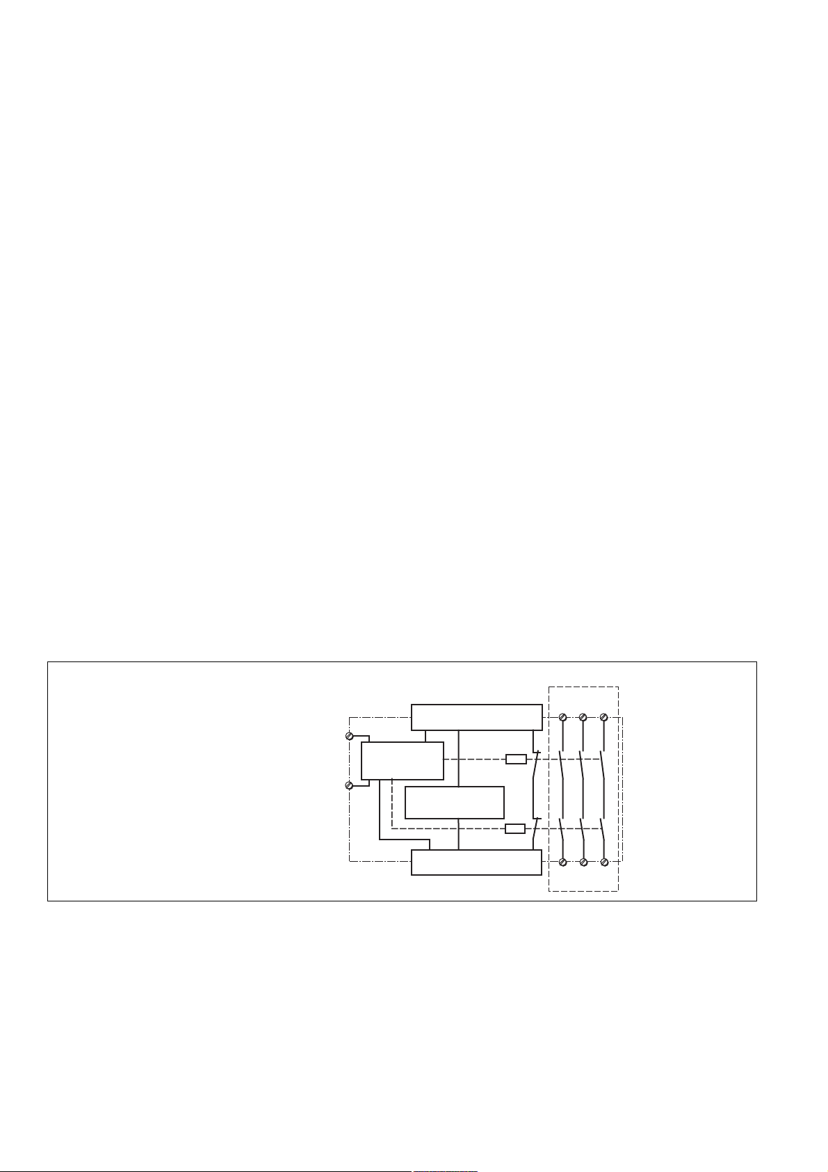
*Sichere Trennung nach EN 60947-1, 6 kV/*Safe separation in accordance with EN 60947-1, 6 kV/
*Séparation galvanique selon EN 60947-1, 6 kV
PNOZpower-Bus
Externer
Start/Stopp-Eingang
External start/stop input
Entrée Start/stop externe
Y39
Y40
Eingangskreise
Input circuit
circuit d'entree
feedback control loop
boucle de retour
K1
Rückführkreis
K2
PNOZpower-Bus
Fig. 1: Innenschaltbild/Internal Wiring Diagram/Schéma de principe
Montage
• Das Sicherheitsschaltgerät muss in einen
Schaltschrank (min. IP54) eingebaut
werden. Zur Befestigung auf einer
Tragschiene dienen vier Rastelemente auf
der Rückseite des Geräts.
• Montieren Sie das Gerät auf eine waagrechte Tragschiene. Bei anderen Einbaulagen können die in den techn. Daten
angegebenen Werte für das Schaltvermögen nicht eingehalten werden.
• Das Erweiterungsmodul PNOZ po3.3p
kann an beliebiger Stelle des modularen
Sicherheitssystems PNOZpower montiert
Installation
• The safety relay must be installed in a
control cabinet (min. IP54). There are four
notches on the back of the unit for DIN rail
attachment.
• Fit the unit to a horizontal DIN rail. In other
mounting positions, the values given in the
technical details for the switching capability
may not be achieved.
• The PNOZ po3.3p expander module can
be installed in any position on the
PNOZpower modular safety system.
• There are 2 sockets on the rear of the
PNOZ po3.3p. Connect the PNOZ po3.3p
werden.
*
L11L23L3
2T14T26
5
T3
Montage
• Le relais de sécurité doit être monté dans
une armoire avec, au minimum, l’indice de
protection IP54. Sa face arrière, dotée de
4 ergots, peut s’encliqueter sur un profilé
support.
• Montez l’appareil sur un profilé support
horizontal. Les autres positions de
montage ne permettent pas de respecter
les valeurs de commutation indiquées
dans les caractéristiques techniques.
• Le module d’extension PNOZ po3.3p peut
être installé en n’importe quel point du
système de sécurité modulaire
PNOZpower.
- 2 -
Page 3
• Auf der Geräterückseite des PNOZ po3.3p
befinden sich 2 Buchsen. Das
Erweiterungsmodul PNOZ po3.3p wird mit
den anderen Geräten des modularen
Sicherheitssystems PNOZpower über die
mitgelieferten Steckbrücken verbunden.
Beachten Sie: Auf das erste und letzte
Gerät muss ein Abschlussstecker
gesteckt werden (siehe Fig. 2)!
• Nur Abschlussstecker für das modulare
Sicherheitssystem PNOZpower verwenden
(Aufdruck: Sach-Nr. 95579).
• Maximalbestückung eines PNOZpowerSystems:
- 1 Basisgerät
- 4 Erweiterungsmodule
- 1 Netzgerät
expander module to other units in the
PNOZpower modular safety system with
the jumpers supplied.
Please note: Be sure to plug a
terminator in to the first and last units
(see Fig. 2)!
• Only use terminators for the PNOZpower
modular safety system (Catalogue item no.
95579).
• Maximum hardware in a PNOZpower
system:
- 1 base unit
- 4 expander modules
- 1 power supply unit
• La face arrière du PNOZ po3.3p comporte
2 douilles. Le module d’extension PNOZ
po3.2p est relié aux autres appareils du
système de sécurité modulaire
PNOZpower par le biais des cavaliers de
pontage fournis.
Important : le premier et le dernier
appareil doivent être pourvus d’une
fiche de terminaison (voir fig. 2) !
• Utilisez uniquement les fiches de terminaison prévues pour le système de sécurité
modulaire PNOZpower (Référence :
95579).
• Équipement maximal d’un système
PNOZpower :
- 1 appareil de base
- 4 modules d’extension
- 1 bloc d’alimentation
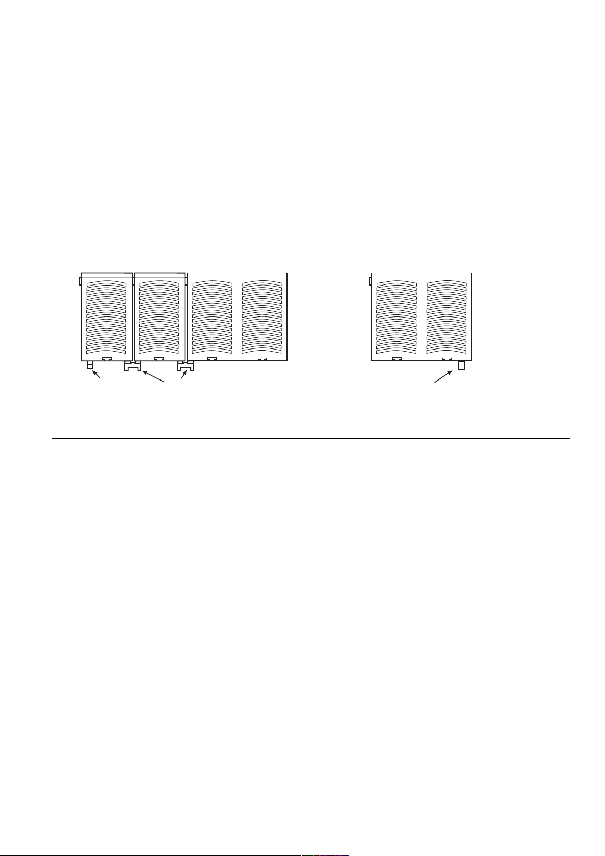
Netzgerät
Power Supply
Bloc
d'alimentation
95579
Abschlussstecker
Terminator
Fiche de
terminaison
Fig. 2: Montage des PNOZ po3.3p/Installation PNOZ po3.3p/Montage du PNOZ po3.3p
Basisgerät
Base Unit
Appareil
de base
95425
Steckbrücke
Link
Cavalier de pontage
Inbetriebnahme
Beachten Sie bei der Inbetriebnahme:
• ACHTUNG
Die steckbaren Anschlussklemmen nur im
spannungslosen Zustand ziehen und
stecken.
• Vor die Ausgangskontakte eine
Sicherung (s. technische Daten)
schalten, um das Verschweißen der
Kontakte zu verhindern.
• Keine kleinen Ströme mit Kontakten
schalten, über die zuvor große Ströme
geführt wurden.
• Leitungsmaterial aus Kupferdraht mit einer
Temperaturbeständigkeit von 60/75 °C
verwenden.
• Das Anzugsdrehmoment der Schrauben
auf den Anschlussklemmen muss 0,5 Nm
betragen.
• Angaben im Kapitel „Technische Daten“
unbedingt einhalten.
Ablauf
• Externer Start-/Stopp-Eingang Y39-Y40:
Brücken oder Taster (Öffnerkontakt)
anschließen
Das Gerät ist eingeschaltet, wenn
• die Versorgungsspannung anliegt (LED
"POWER" leuchtet)
• die Eingangskreise geschlossen sind
Die Sicherheitskontakte 1(L1)-2(T1), 3(L2)4(T2) und 5(L3)-6(T3) sind geschlossen und
die LEDs "CH. 1" und "CH. 2" leuchten. Wird
ein Eingangskreis geöffnet, öffnen die
Sicherheitskontakte 1(L1)-2(T1), 3(L2)-4(T2)
und 5(L3)-6(T3). Die LEDs "CH. 1" und "CH.
2" erlöschen.
Erweiterungsmodul 1
Expander modul 1
Module d'expansion 1
PNOZ po3.3p
Commissioning
When commissioning, please note the
following:
• CAUTION
Only connect and disconnect the plug-in
terminals when isolated from the mains.
• To prevent contact welding, a fuse
should be connected before the output
contacts (see technical details).
• Don’t switch low currents using contacts
that have been used previously with high
currents.
• Use copper wire that can withstand
60/75 °C.
• The torque setting on the connection
terminals should be 0.5 Nm.
• Information given in the “Technical details”
must be followed.
Sequence
• External start/stop input Y39-Y40:
connect links or button (N/C contact)
The unit is ready for operation when:
• the power supply via the PNOZpower bus is
present (“POWER” LED illuminates)
• the input circuits on the base unit are
made
The safety contacts 1(L1)-2(T1), 3(L2)-4(T2)
and 5(L3)-6(T3) are closed, and the LEDs
“CH. 1” and “CH. 2” illuminate. If an input
circuit on the base unit is open, then the
safety contacts 1(L1)-2(T1), 3(L2)-4(T2) and
5(L3)-6(T3) open also. The LEDs “CH. 1”
and “CH. 2” go out.
Erweiterungsmodul 4
Expander modul 4
Module d'expansion 4
95579
Abschlussstecker
Terminator
Fiche de
terminaison
Mise en service
Points importants pour la mise en service :
• ATTENTION
Ne branchez et débranchez les borniers
de raccordement débrochables que
lorsque l’alimentation est coupée.
• Raccordez un fusible (voir les caracté-
ristiques techniques) avant les contacts
de sortie afin d’éliminer tout risque de
fusion.
• Ne commutez pas de courants de faible
intensité avec des contacts ayant servi à
des courants de forte intensité.
• Utilisez uniquement des fils de câblage en
cuivre résistant à des températures de 60/
75 °C.
• Le couple de serrage des vis doit être de
0,5 Nm au niveau des borniers.
• Respectez impérativement les instructions
données dans le chapitre “Caractéristiques
techniques”.
Procédure
• Circuit start/Stop externe Y39-Y40 : ponter
les 2 bornes ou relie un bouton poussoir
(contact à fermeture)
L’appareil est enclenché lorsque
• la tension d’alimentation est appliquée via le
bus PNOZpower (LED “POWER” allumée)
• les circuits d’entrée de l’appareil de base
sont fermés
Les contacts de sécurité 1(L1)-2(T1), 3(L2)4(T2) et 5(L3)-6(T3) sont fermés et les LEDs
“CH. 1” et “CH. 2” sont allumées. Si un circuit
d’entrée de l’appareil de base est ouvert, les
contacts de sécurité 1(L1)-2(T1), 3(L2)-4(T2)
et 5(L3)-6(T3) s’ouvrent et les LEDs “CH. 1”
et “CH. 2” s’éteignent.
- 3 -
Page 4
Anwendung
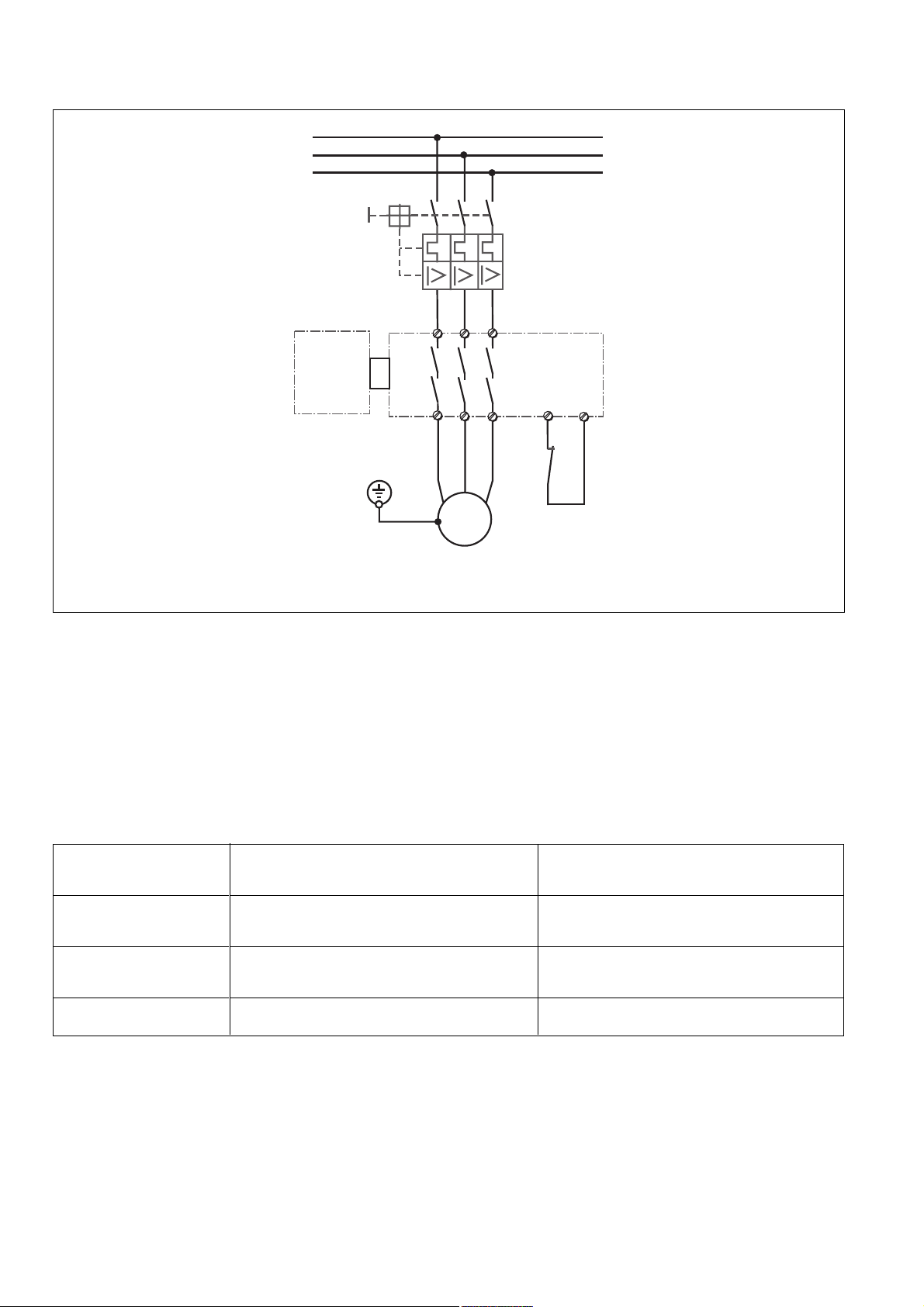
Fig. 3 ist ein Anschlussbeispiel für eine
Motorlast AC3.
Use
Fig. 3 is a connection example for a motor
load A3.
L1
L2
L3
Q1
L1
L2
1
3
Grundgerät
Base unit
Appareil
de base
L3
Application
La Fig. 3 est un exmeple de câblage pour
une charge AC3.
5
PNOZ po3.3p
4
T2
3~
6
T3
M
2
T1
Fig. 3: Anschlussbeispiel für Motorlast AC3/Connection example for motor load AC3/
exemple de câblage pour une charge AC3.
Koordination nach
IEC / EN 60947-4-1
• Die folgende Koordinationstabelle dient zur
Auswahl von Motorschutzschaltern, deren
Einsatz eine verschweißfreie Kontaktabsicherung des PNOZ po3.3p bei Kurzschlüssen im 1 kA-Netz ermöglichen.
• Eine verschweißfreie Kontaktabsicherung
des PNOZ po3.3p muss gegeben sein, um
die Sicherheitsfunktion des PNOZ po3.3p
nach EN 954-1, Kategorie 4 zu erfüllen.
Motorleistung/
motor performance/
Circuit puissance AC3
3 kW
4 kW
5,5 kW
Hersteller, Typ/Manufacturer, type/Fabricant, type
Prüfspannung/test voltage/Tension d'essai
3 x 420 V AC
ABB MS 325-9
Moeller PKZM0-6,3
Telemecanique GV2-LE14
ABB MS 325-9
Moeller PKZM0-10
Telemecanique GV2-LE14
ABB MS 325-12,5
Moeller PKZM0-10
Coordination in accordance with
IEC / EN 60947-4-1
• The following coordination table is used to
select a motor protecting switch , which
enables an unwelded contact fuse
protection of the PNOZ po3.3p if short
circuits occur in the 1 kA mains.
• An unwelded contact fuse protection of
the PNOZ po3.3p must be available in
order to comply with the safety function of
the PNOZ po3.3p in accordance with EN
954-1, category 4.
Y39
Y40
S1
S1: Externer Start/Stopp-Eingang
External start/stop input
Entrée start/stop externe
Coordination d'après
IEC / EN 60947-4-1
• Le tableau ci-dessus permet de
déterminer les dijoncteurs moteurs qui
garantissent une protection optimale des
contacts du PNOZ po3.3p en cas de courtcircuit dans un réseau de 1 KA.
• Une protection contre le soudage des
contacts du PNOZ po3.3p doit être
garantiepour répondre aux exigences de
la catégorie 4 selon EN 954-1
Hersteller,Typ/Manufacturer, type/Fabricant, type
Prüfspannung/test voltage/Tension d'essai
3 x 480 V AC
ABB MS 325-6,3
Moeller PKZM0-6,3
Telemecanique GV2-LE10
ABB MS 325-9
Moeller PKZM0-10
---
• Weitere Informationen auf Anfrage.
• Zusätzlich zu den Angaben in der
Koordinationstabelle sind die Herstellerangaben zu den entsprechenden Motorschutzschaltern zu beachten.
• Bei kleineren Motorleistungen ist ein
entsprechender Motorschutzschalter aus
den Katalogen eines der oben genannten
Hersteller zu wählen.
• More information available on request.
• In addition to the information in the
coordinaton table, the manufacturer's
instructions on the corresponding motor
protecting switch are to be consulted.
• For lower motor performances, select a
corresponding motor protecting switch
from the catalogues of one of the
manufacturers above.
- 4 -
• Autres informations sur demande.
• Tenir compte également des données
techniques préconisés par les fabricants
des dijoncteurs
• Pour des puissance moteurs plus faibles,
un dijoncteur moteur adapté doit être
sélectionné dans les catalogues des
fabricants cités dans le tableau.
Page 5

Fehler - Störungen
Durch Schließen bzw. Unterbrechen der
Eingangskreise am Grundgerät kann
überprüft werden, ob das PNOZ po3.3p
ordnungsgemäß ein- bzw. ausschaltet.
Das Gerät kann aus Sicherheitsgründen bei
folgenden Fehlern nicht gestartet werden:
• Fehlfunktion der Kontakte (LED "FAULT"
leuchtet):
Da das PNOZ po3.3p mit einem Grundgerät verschaltet wird, ist bei verschweißten Kontakten nach Öffnen des Eingangskreises keine neue Aktivierung möglich.
• Leitungsunterbrechung, Kurz- oder
Erdschluss (z. B. im Eingangskreis des
Grundgeräts)
Faults – Interference
You check whether the PNOZ po3.3p has
been switched on or off correctly by closing
or opening the input circuits on the base unit.
For safety reasons, the unit will not start if
any of the following faults is present:
• Contact function faulty
(“FAULT” LED illuminates):
As the PNOZ po3.3p is wired to a base
unit, it cannot be re-activated if the
contacts weld after the input circuit is
opened.
• Open circuit, short circuit or earthing fault
(e.g. in the base unit input circuit)
Erreurs – Dysfonctionnements
La fermeture ou l’interruption des circuits
d’entrée de l’appareil de base permettent de
surveiller si le PNOZ po3.3p s’enclenche et
se désenclenche correctement.
Pour des raisons de sécurité, l’appareil ne
peut pas démarrer avec les erreurs suivantes :
• Dysfonctionnement des contacts (LED
“FAULT” allumée) :
Le PNOZ po3.3p étant branché sur un
appareil de base, une nouvelle activation
après ouverture du circuit d’entrée est
impossible lorsque les contacts sont
soudés.
• Coupure de ligne, court-circuit ou défaut à
la masse (par ex. dans le circuit d’entrée
de l’appareil de base)
Technische Daten/Technical Data/Caractéristiques techniques
Versorgungsspannung UB/Operating Voltage UB/Tension d’alimentation U
Spannungstoleranz/Voltage Tolerance/Plage de la tension d’alimentation -15 % / +10 %
Leistungsaufnahme bei UB/Power Consumption/Consommation pour U
Ausgangskontakte nach EN 954-1, EN ISO 13849-1 Kategorie 4 3 Sicherheitskontakte (S)
Output Contacts to EN 954-1, EN ISO 13849-1 category 4 3 Safety Contacts (N/O)
Contacts de sortie d'après EN 954-1, EN ISO 13849-1 catégorie 4 3 contacts de sécurité (F)
Kontaktwerkstoff/Contact Material/Matériau des contacts AgCdO
Gebrauchskategorie nach/Utilization category to/Catégorie d’utilisation d'après
EN 60947-4-1 AC1:240 V/0,21 ... 16A/4000 VA
EN 60947-5-1 AC15: 230 V/6 A; DC13: 24 V/1,5 A
Kontaktabsicherung extern/External Contact Fuse Protection/Protection des contacts
(EN 60947-5-1)
Schmelzsicherung/Blow-out fuse/Fusibles 16 A gG flink/quick acting/rapide oder/or/ou
Mechanische Lebensdauer/Mechanical Life/Durée de vie mécanique 1 x 10⁷ Schaltspiele/cycles/manoeuvres
Elektrische Lebensdauer/Electrical Life/Durée de vie électrique (10 A/230V AC, cos ϕ = 1) 1 x 10⁶ Schaltspiele/cycles/manoeuvres
Einschaltverzögerung/Switch-on delay/Temps de réarmement UB = 24 V DC
Automatischer Start/Automatic reset/Réarmement automatique typ. 17 ms, max. 30 ms
Automatischer Start nach Netz-Ein/Automatic reset after Power-ON/ typ. 90 ms, max. 150 ms
Réarmement automatique après mise sous tension
Rückfallverzögerung /Delay-on De-Energisation /Temps de retombée UB = 24 V DC
bei NOT-AUS/at E-STOP/en cas d'arrêt d'urgence typ. 40 ms, max. 60 ms
bei Netzausfall/with power failure/en cas de coupure d'alimentation typ. 32 ms, max. 50 ms
Umgebungstemperatur/Operating Temperature/Température d’utilisation -10 ... + 55 °C
Lagertemperatur/Storage Temperature/Température de stockage -40 ... +85 °C
Klimabeanspruchung/Climate Suitability/Conditions climatiques EN 60068-2-78
EMV/EMC/CEM EN 60947-5-1, EN 61000-6-2, EN 61000-6-3
Luft- und Kriechstrecken nach/Airgap Creepage to/Cheminement et claquage d'après EN 60947-1
Verschmutzungsgrad/Pollution degree/Niveau d'encrassement 2
Bemessungsisolationsspannung/Rated insulation voltage/Tension assignée d'isolement 400 V
Bemessungsstoßspannungsfestigkeit/Rated impulse withstand voltage/Tension assignée
de tenue aux chocs 6 kV
Schwingungen nach/Vibrations to/Vibrations d'après EN 60068-2-6 Frequenz/Frequency/Frequence: 10 ... 55 Hz
Schutzart/Protection/Indice de protection
Einbauraum/Min. mounting (eg. panel)/Lieu d'implantation (ex. armoire) IP54
Gehäuse/Housing/Boîtier IP30
Klemmenbereich/Terminals/Bornes IP20
Querschnitt des Außenleiters Einzelleiter oder mehrdrähtiger Leiter mit
Cable cross section Adernendhülse/single-core or multicore
Raccordement with crimp connectors/fils séparés ou fils
B
B
über PNOZpower-Bus/via PNOZpower Bus/
via le bus PNOZpower
5,5 W
400 V/0,21 ... 10 A/4000 VA
(1 x 10⁶ Schaltspiele/cycles/
manoeuvres)
500 V/0,21 ... 8 A/4000 VA
AC3:240 V/3 kW
400 V/5,5 kW
(7 x 10⁵ Schaltspiele/cycles/
manoeuvres)
500 V/4 kW
DC1: 24 V/0,21 ... 16 A/400 W
16 A gG träge/slow acting/normeaux
+ Basisgerät/Base unit/appareil de base
+ Basisgerät/Base unit/appareil de base
Amplitude/Amplitude/Amplitude: 0,35 mm
groupés avec embout:
0,50 ... 4,00 mm2, 20 - 10 AWG
- 5 -
Page 6

Anzugsdrehmoment für Anschlussklemmen (Schrauben)/Torque setting for connection 0,50 Nm
terminal screw/couple de serrage (bornier)
Gehäusematerial/Housing material/Matériau boîtier Kunststoff/Plastic/Plastique
Gehäuse/Housing/Boîtier PPO UL 94 V0
Front/Front/Face avant ABS UL 94 V0
Abmessungen H x B x T/Dimensions H x W x D/Dimensions H x P x L 94 x 90 x 135 mm
Gewicht/Weight/Poids 620 g
Es gelten die 2008-06 aktuellen Ausgaben
der Normen.
The version of the standards current at
2008-06 shall apply.
Se référer à la version des normes en vigeur
au 2008-06.
Konventioneller thermischer Strom bei gleichzeitiger Belastung mehrerer Kontakte/Conventional thermal
current while loading several contacts/Courant thermique conventionnel en cas de charge sur plusieurs
contacts (AC1, DC1)
Anzahl der Kontakte/number of contacts/nombre des contacts 3 2 1
Ith (24 V DC/ 240 V AC) 12 A 16 A 16 A
Ith (400 V AC) 7,5 A 10 A 10 A
(500 V AC) 6 A 8 A 8 A
I
th
Lebensdauer der Ausgangskontakte/Service Life of Output contacts/Durée de vie des contacts de sortie
20
DC1: 24 V
3
AC3: 400 V
AC1: 400 V
10
AC15: 230 V
1
Courant coupé (A)
Nennbetriebstrom (A)
Nominal operating current (A)
0.1
10 100 1000 10000
Schaltspielzahl x 10
Cycles x 10
Nombre de manvres x 10
DC13: 24 V
3
3
- 6 -
Page 7

Abmessungen in mm (")/Dimensions in mm (")/Dimensions en mm (")
121 (4.76")
135 (5.31")
94 (3.70")
EG-Konformitätserklärung:
Diese(s) Produkt(e) erfüllen die Anforderungen der Richtlinie 2006/42/EG über Maschinen des europäischen Parlaments und des
Rates.
Die vollständige EG-Konformitätserklärung
finden Sie im Internet unter www.pilz.com
Bevollmächtigter: Norbert Fröhlich,
Pilz GmbH & Co. KG, Felix-Wankel-Str. 2,
73760 Ostfildern, Deutschland
90 (3.54")
EC Declaration of Conformity:
This (these) product(s) comply with the
requirements of Directive 2006/42/EC of the
European Parliament and of the Council on
machinery.
The complete EC Declaration of Conformity
is available on the Internet at www.pilz.com
Authorised representative: Norbert Fröhlich,
Pilz GmbH & Co. KG, Felix-Wankel-Str. 2,
73760 Ostfildern, Germany
Déclaration de conformité CE :
Ce(s) produit(s) satisfait (satisfont) aux
exigences de la directive 2006/42/CE relative
aux machines du Parlement Européen et du
Conseil.
Vous trouverez la déclaration de conformité
CE complète sur notre site internet
www.pilz.com
Représentant : Norbert Fröhlich,
Pilz GmbH & Co. KG, Felix-Wankel-Str. 2,
73760 Ostfildern, Allemagne
- 7 -
Page 8

Technischer Support
+49 711 3409-444 +49 711 3409-444
...
In vielen Ländern sind wir durch
unsere Tochtergesellschaften und
Handelspartner vertreten.
Nähere Informationen entnehmen
Sie bitte unserer Homepage oder
nehmen Sie Kontakt mit unserem
Stammhaus auf.
Technical support
... ...
In many countries we are
represented by our subsidiaries
and sales partners.
Please refer to our Homepage
for further details or contact our
headquarters.
Assistance technique
+49 711 3409-444
Nos filiales et partenaires
commerciaux nous représentent
dans plusieurs pays.
Pour plus de renseignements,
consultez notre site internet ou
contactez notre maison mère.
- 8 -
www
www.pilz.com
Pilz GmbH & Co. KG
Felix-Wankel-Straße 2
73760 Ostfildern, Germany
Telephone: +49 711 3409-0
Telefax: +49 711 3409-133
E-Mail: pilz.gmbh@pilz.de
Originalbetriebsanleitung/Original instructions/Notice originale
20 678-05-2010-08 Printed in Germany
Page 9

20 678-05
PNOZ po3.3p
4 E Instrucciones de uso
4 I Istruzioni per l`uso
4 NL Gebruiksaanwijzing
Prescripciones de seguridad
• El dispositivo tiene que ser instalado y puesto
en funcionamiento exclusivamente por
personas que estén familiarizadas, tanto con
estas instrucciones de uso como con las
prescripciones vigentes relativas a la
seguridad en el trabajo y a la prevención de
accidentes. Hay que observar tanto las
prescripciones VDE como las prescripciones
locales, especialmente en lo que se refiere a
las medidas de protección.
• Durante el transporte, el almacenaje y el
funcionamiento hay que atenerse a las
condiciones conforme a EN 60068-2-6 (ver
datos técnicos).
• La garantía se pierde en caso de que se
abra la carcasa o se lleven a cabo
modificaciones por cuenta propia.
• Montar el dispositivo dentro de un armario de
distribución; en caso contrario es posible que
el polvo y la suciedad puedan afectar el
funcionamiento.
• Hay que cuidar de que haya un conexionado
de seguridad suficiente en todos los
contactos de salida con cargas capacitivas e
inductivas.
Campo de aplicación adecuado
El módulo de ampliación PNOZ po3.3p sólo se
puede usar con un dispositivo básico o con un
módulo de excitación del sistema de seguridad
modular PNOZpower.
El PNOZ po3.3p está diseñado para ser
empleado en
• dispositivos de PARADA DE EMERGENCIA
• circuitos de seguridad según EN 60204-1
(VDE 0113-1) e IEC 60204-1
La categoría a realizar según EN 954-1
depende de la categoría del dispositivo base.
No puede superar la categoría del bloque de
ampliación de contactos.
Norme di sicurezza
• Il dispositivo può venire installato e messo in
funzione solo da persone che hanno
acquisito familiarità con le presenti istruzioni
per l’uso e le disposizioni vigenti in materia di
sicurezza di lavoro e antinfortunistica.
Osservare le disposizioni della VDE nonché
le norme locali, soprattutto per quanto
riguarda le misure preventive di protezione.
• Per il trasporto, l’immagazzinamento e
l’esercizio attenersi alle condizioni a norma
EN 60068-2-6 (v. Dati tecnici).
• Se viene aperta la custodia oppure se
vengono apportate modifiche in proprio,
decade qualsiasi diritto di garanzia.
• Montare il dispositivo in un armadio elettrico;
altrimenti la polvere e l’umidità possono
pregiudicare le funzioni.
• Occorre dotare tutti i contatti di uscita dei
carichi capacitivi e induttivi con un circuito di
sicurezza sufficiente.
Uso previsto
Il modulo di espansione PNOZ po3.3p può
essere utilizzato soltanto congiuntamente ad un
dispositivo base o ad un modulo di comando
del sistema di sicurezza modulare PNOZpower.
Il PNOZ po3.3p è concepito per essere
utilizzato in
• dispositivi di arresto di emergenza
• circuiti elettrici di sicurezza conformi alle
norme EN 60204-1 (VDE 0113-1) e IEC
60204-1
La categoria da realizzare secondo la norma
EN 954-1dipende dalla categoria del dispositivo
base. Essa non può essere superata dal
modulo di espansione contatti
Veiligheidsvoorschriften
• Het apparaat mag uitsluitend worden
geïnstalleerd en in bedrijf genomen door
personen die vertrouwd zijn met deze
gebruiksaanwijzing en met de geldende
voorschriften op het gebied van arbeidsveiligheid en ongevallenpreventie. Neemt u
de van toepassing zijnde Europese richtlijnen
en de plaatselijke voorschriften in acht, in het
bijzonder m.b.t. veiligheidsmaatregelen.
• Neemt u bij transport, opslag en in bedrijf de
richtlijnen volgens EN 60068-2-6 in acht (zie
technische gegevens).
• Het openen van de behuizing of het
eigenmachtig veranderen van de schakeling
heeft verlies van de garantie tot gevolg.
• Monteert u het apparaat in een schakelkast.
Stof en vochtigheid kunnen anders de
werking nadelig beïnvloeden.
• Zorg bij capacitieve of inductieve belasting
van de uitgangscontacten voor adequate
contactbeschermingsmaatregelen.
Gebruik volgens de voorschriften
De uitbreidingsmodule PNOZ po3.3p mag
alleen worden gebruikt met een basismodule of
aanstuurmodule van het modulaire
veiligheidssysteem PNOZpower.
De PNOZ po3.3p is bestemd voor gebruik in
• noodstopvoorzieningen
• veiligheidscircuits volgens EN 60204-1
(VDE 0113-1) en IEC 60204-1
De te realiseren categorie volgens EN 954-1 is
afhankelijk van de categorie van het
basisrelais. De categorie kan door het
contactuitbreidingsrelais niet overschreden
worden.
Descripción del dispositivo
El módulo de ampliación PNOZ po3.3p está
montado dentro de una carcasa P-01. La
tensión de alimentación es puesta a disposición
por el dispositivo básico a través del bus
PNOZpower.
Características:
• Contactos de salida:
3 contactos de seguridad (NA), de guiado
mecánico
• Separación segura de los contactos de
seguridad L1-T1, L2-T2, L3-T3 y del bus
PNOZpower
• Indicación de estado de conmutación de los
canales 1/2, tensión de alimentación y fallo
• Los circuitos de entrada y la tensión de
alimentación van por el bus PNOZpower
• Apropiado para la conexión segura de
cargas con la categoría de uso AC3 (p. ej.
motor)
• Entrada externa de parada/arranque para la
conexión no orientada a la seguridad de una
carga
• Se pueden conectar como máx. 4 módulos
de ampliación a un dispositivo básico
Descrizione
Il modulo di espansione PNOZ po3.3p è
alloggiato in una custodia P-01. La tensione di
alimentazione viene trasmessa dal dispositivo
base tramite il bus PNOZpower.
Caratteristiche:
• Contatti di uscita:
3 contatti di sicurezza (NA), con contatti
guidati
• separazione sicura dei contatti di
sicurezza L1-T1, L2-T2, L3-T3 e del bus
PNOZpower
• Visualizzazione dello stato di commutazione
canale 1/2, della tensione di alimentazione e
di eventuali guasti
• Circuiti di ingresso e tensione di alimentazione su bus PNOZpower
• Adatto anche per collegare in sicurezza i
carichi di categoria di utilizzo AC3 (p. es. i
motori)
• Entrata esterna Start-/Stop per il collegamento non sicuro di un carico
• Max. 4 moduli di espansione collegabili ad
un dispositivo base
- 9 -
Apparaatbeschrijving
De uitbreidingsmodule PNOZ po3.3p is in een
P-01-behuizing ondergebracht. De
voedingsspanning wordt geleverd door de
basismodule via de PNOZpower-bus.
Kenmerken:
• Uitgangscontacten:
3 veiligheidscontacten (M), mechanisch
gedwongen
• Veilige scheiding van de veiligheidscontacten L1-T1, L2-T2, L3-T3 van de
PNOZpower-bus
• Statusweergave voor schakeltoestand
kanaal 1/2, voedingsspanning en storing
• Ingangscircuits en voedingsspanning via
PNOZpower-bus uitgevoerd
• Geschikt voor het veilige schakelen van
belastingen met gebruikscategorie AC3 (b.v.
motor)
• Externe start-stopingang voor het nietveiligheidsrelevant schakelen van een
belasting
• Max. 4 uitbreidingsmodulen kunnen op een
basismodule aangesloten worden
Page 10

• Conexión con el dispositivo básico y entre
los módulos de ampliación a través del bus
PNOZpower mediante puentes insertables
en la parte posterior del aparato
El dispositivo cumple los requerimientos de
seguridad siguientes:
• El circuito está estructurado de modo
redundante con autosupervisión (EN 954-1,
categoría 4).
• El equipo de seguridad permanece activo
aún cuando falle uno de los componentes.
• En cada ciclo de conexión/desconexión de la
máquina, se verifica automáticamente, si los
contactos de salida del dispositivo de
seguridad abren y cierran correctamente.
• Collegamento con il dispositivo base e tra i
moduli di espansione mediante bus
PNOZpower con ponticelli sul retro del
dispositivo
Il dispositivo elettrico risponde ai seguenti
requisiti di sicurezza:
• Il circuito è strutturato in modo ridondante
con autocontrollo (EN 954-1, categoria 4).
• Il dispositivo di sicurezza funziona anche in
caso di guasto di un componente.
• Per ciascun ciclo di inserimentodisinserimento della macchina, viene
eseguita la verifica automatica della corretta
apertura e chiusura dei contatti del
dispositivo di sicurezza.
• Verbinding met de basismodule en tussen de
uitbreidingsmodulen via PNOZpower-bus
met busconnectoren op de achterzijde van
het apparaat
Het relais voldoet aan de volgende veiligheidseisen:
• De schakeling is redundant met zelfbewaking opgebouwd (EN 954-1, categorie
4).
• Ook bij uitvallen van een component blijft de
veiligheidsschakeling werken.
• Bij elke aan-uitcyclus van de machine
wordt automatisch getest of de
uitgangscontacten van de
veiligheidsvoorziening correct openen en
sluiten.
Descripción del funcionamiento
El PONZ po3.3p ofrece 3 contactos de
seguridad para el sistema de seguridad
modular PNOZpower. Junto con el dispositivo
básico, sirve para interrumpir por razones de
seguridad un circuito de seguridad. Los
contactos de seguridad están gobernados por
el dispositivo básico. La tensión de
alimentación, circuitos de entrada y circuito de
realimentación son conducidos a través del bus
PNOZpower.
Tan pronto como
• se conecte la tensión de alimentación (LED
"POWER" se ilumina),
• se cierre la entrada externa de rearme/
parada Y39-Y40
• y se cierren los circuitos de entrada 1 y 2 en
el dispositivo básico,
pasan ambos relés de salida K1 y K2 a la
posición de trabajo. Los contactos de seguridad
1(L1)-2(T1), 3(L2)-4(T2) y
5(L3)-6(T3) se cierran. Los LEDs "CH. 1" y
"CH. 2" se iluminan.
Si se abren los circuitos de entrada en el
dispositivo básico o la entrada externa de
rearme/parada Y39-Y40:
Se abren los contactos de seguridad de guía
forzada 1(L1)-2(T1), 3(L2)-4(T2) y
5(L3)-6(T3).
Si se abren los circuitos de entrada en el
dispositivo básico: se apagan los LEDs
"CH. 1" y "CH. 2".
Si se abre la entrada externa de rearme/parada
Y39-Y40: se apaga el LED "CH. 2".
Descrizione del funzionamento
Il dispositivo PNOZ po3.3p prevede 3 contatti di
sicurezza per il sistema di sicurezza modulare
PNOZpower e insieme al dispositivo base
serve ad interrompere per motivi di sicurezza
un circuito elettrico di sicurezza. I contatti di
sicurezza sono controllati dal dispositivo base.
Tensione di alimentazione, circuiti di entrata e
circuito di retroazione sono gestiti mediante il
bus PNOZpower.
Non appena:
• è presente la tensione di alimentazione (il
LED "POWER" è acceso).
• l’entrata esterna Start-/Stop Y39-Y40 è
chiusa
• i circuiti di ingresso 1 e 2 sul dispositivo base
sono chiusi,
i relè di uscita K1 e K2 passano in posizione di
lavoro. I contatti di sicurezza 1(L1)-2(T1), 3(L2)4(T2) e 5(L3)-6(T3) si chiudono. I LED "CH. 1"
e "CH. 2" si accendono.
Apertura dei circuiti di ingresso del dispositivo
base o dell’entrata esterna start/stop
Y39-Y40:
I contatti di sicurezza forzati 1(L1)-2(T1), 3(L2)4(T2) e 5(L3)-6(T3) si aprono.
Apertura dei circuiti di ingresso del
dispositivo base: I LED "CH. 1" e "CH. 2" si
spengono.
Apertura dell’entrata esterna start/stop
Y39-Y40: Il LED "CH. 2" si spegne.
Functiebeschrijving
De PNOZ po3.3p heeft 3 veiligheidscontacten
voor het modulaire veiligheidssysteem
PNOZpower. Het apparaat dient samen met de
basismodule om een veiligheidscircuit veilig te
onderbreken. De veiligheidscontacten worden
door de basismodule aangestuurd. Voedingsspanning, ingangscircuits en terugkoppelcircuit
worden via de PNOZpower-bus uitgevoerd.
Zodra de
• voedingsspanning ingeschakeld is (LED
"POWER" licht op),
• de externe start-stopingang Y39-Y40
gesloten is
• en de ingangscircuits 1 en 2 op de
basismodule gesloten zijn,
worden de beide uitgangsrelais K1 en K2
bekrachtigd. De veiligheidscontacten
1(L1)-2(T1), 3(L2)-4(T2) en 5(L3)-6(T3) sluiten.
De LED’s "CH. 1" en "CH. 2" lichten op.
Openen van de ingangscircuits op het
basisrelais of van de externe start-stopingang
Y39-Y40:
De mechanisch gedwongen veiligheidscontacten 1(L1)-2(T1), 3(L2)-4(T2) en
5(L3)-6(T3) gaan open.
Openen van de ingangscircuits op het
basisrelais: De LED’s "CH. 1" en "CH. 2"
doven.
Openen van de externe start-stopingang Y39Y40: De LED "CH. 2" doven.
*Separación segura conforme a EN60947-1, 6 kV/*Separazione sicura secondo EN60947-1, 6 kV/*Veilige scheiding volgens EN60947-1, 6 kV
*
PNOZpower-Bus
Entrada externa
de parada/arranque
Ingresso esterno
di start/stop
Externe
start-stopingang
Y39
Y40
Circuito de entrada
Circuito di ingresso
Ingangscircuit
Circ. de realimentación
Circ. di retroazione
Terugkoppelcircuit
PNOZpower-Bus
Fig. 1: Esquema de conexionado interno/Schema di collegamento interno/Intern schema
Montaje
• El relé de seguridad tiene que ser montado
dentro de un armario de distribución (IP54
como mínimo). Los cuatro elementos de
encaje de la parte trasera del dispositivo
sirven para fijarlo en una guía portante.
Montaggio
• Il modulo di sicurezza deve venire montato in
un armadio elettrico (grado di protezione
minimo IP54). Per il fissaggio su una guida,
sono previsti quattro dispositivi a scatto sul
retro del dispositivo.
• Montar el equipo en una guía normalizada
horizontal. Si se monta en otra posición, no
- 10 -
L11L23L3
K1
K2
Montage
• Het veiligheidsrelais dient ingebouwd te
• Monteer het apparaat op een horizontale
5
2T14T26
T3
worden in een schakelkast (min. IP54).
Bevestiging op een DIN-rail is mogelijk via
vier relaisvoeten op de achterzijde van het
apparaat.
draagrail. Bij andere inbouwposities kan niet
Page 11

se mantendrán los valores del poder de corte
indicados en las características técnicas.
• El módulo de ampliación PNOZ po3.3p se
puede montar en cualquier lugar dentro del
sistema de seguridad modular PNOZpower.
• En la parte posterior del PNOZ po3.3p hay
dos 2 conectores hembra. El módulo de
ampliación PNOZ po3.3p se conecta a los
otros dispositivos del sistema de seguridad
modular PNOZpower mediante los puentes
insertables suministrados con él.
Hay que tener en cuenta: ¡Es necesario
insertar una clavija de terminación en el
primer y otra en el último aparato (véase
Fig. 2)!
• Utilizar exclusivamente clavijas de
terminación del sistema de seguridad
modular PNOZpower (marcados: N.º de
referencia 95579).
• Número máximo de módulos admitidos por
un sistema PNOZpower:
- 1 dispositivo básico
- 4 módulos de ampliación
- 1 fuente de alimentación
• Montare il dispositivo su una guida
orizzontale. Nel caso di posizioni di
installazione diverse, i valori indicati nei dati
tecnici per il potere di interruzione non
possono essere rispettati.
• Il modulo di espansione PNOZ po3.3p può
essere montato in un punto qualsiasi del
sistema di sicurezza modulare PNOZpower.
• Sul retro del dispositivo PNOZ po3.3p sono
previste 2 boccole. Il modulo di espansione
PNOZ po3.3p viene collegato agli altri
dispositivi del sistema di sicurezza modulare
PNOZpower mediante i ponticelli forniti.
Nota bene: sul primo e sull’ultimo
dispositivo è necessario inserire un
connettore terminale (v. fig. 2).
• Utilizzare soltanto il connettore terminale per
il sistema di sicurezza modulare PNOZpower
(stampigliatura: N. 95579)
• Dotazione massima di un sistema
PNOZpower:
- 1 dispositivo base
- 4 moduli di espansione
- 1 alimentatore di rete
voldaan worden aan de waarden die in de
techn. gegevens voor het schakelvermogen
zijn opgegeven.
• De uitbreidingsmodule PNOZ po3.3p kan op
een willekeurige plaats van het modulaire
veiligheidssysteem PNOZpower gemonteerd
worden.
• Op de achterzijde van de PNOZ po3.3p
bevinden er zich 2 busaansluitingen. De
uitbreidingsmodule PNOZ po3.3p wordt
verbonden met de andere apparaten van het
modulaire veiligheidssysteem PNOZpower
via de meegeleverde busconnectoren.
Let u op het volgende: Op het eerste en
laatste apparaat moet er een afsluitconnector geplaatst worden (zie fig. 2)!
• Alleen afsluitconnectoren voor het modulaire
veiligheidssysteem PNOZpower gebruiken
(voorzien van artikelnr. 95579).
• Maximale bezetting van een PNOZpowersysteem:
- 1 basismodule
- 4 uitbreidingsmodulen
- 1 voedingsmodule
Fuente de
alimentación
Alimentatore
Voedingsmodule
95579
Terminador
Connettore
terminale
Afsluitconnector
Fig. 2: Montaje del PNOZ po3.3p/Montaggio del PNOZ po3.3p/Montage van de PNOZ po3.3p
Dispositivo
básico
Dispositivo
base
Basismodule
95425
Puente insertable
Ponticello
Busconnector
Puesta en marcha
Al poner en marcha el dispositivo hay que tener
en cuenta:
• ATENCION
Los bornes de conexión insertables sólo se
deben insertar o extraer cuando se
encuentren libres de tensión.
• Se debe poner en el circuito un fusible
antes de los contactos de salida (véase
características técnicas), para evitar la
fusión de los contactos.
• No se deben conmutar corrientes pequeñas
con contactos que se hayan utilizado
anteriormente con corrientes fuertes.
• Utilizar para las líneas material de alambre
de cobre con una resistencia a la temperatura de 60/75 °C.
• El par de apriete de los tornillos de los
bornes de conexión debe ser 0,5 Nm.
• Respetar sin falta las indicaciones del
capítulo "Datos técnicos".
Secuencia
• Entrada externa de rearme/parada Y39-Y40:
conectar puente o pulsador (contacto
normalmente cerrado)
El dispositivo está conectado cuando
• se conecta la tensión de alimentación (LED
"POWER" se ilumina)
• los circuitos de entrada están cerrados
Los contactos de seguridad 1(L1)-2(T1), 3(L2)4(T2) y 5(L3)-6(T3) se cierran y los LEDs
"CH. 1" y "CH. 2" se iluminan. Si se abre un
Módulo de ampliación 1
Modulo di ampliamento 1
Uitbreidingsmodule 1
PNOZ po3.3p
Messa in funzione
Alla messa in funzione occorre osservare:
• ATTENZIONE!
Innestare e staccare i morsetti di collegamento inseribili soltanto in assenza di
tensione.
• Per evitare la saldatura dei contatti,
collegare un fusibile (vedi dati tecnici) a
monte dei contatti di uscita.
• Non commutare piccole correnti con contatti
attraverso i quali sono state commutate in
precedenza correnti alte.
• Per i cavi utilizzare materiale in filo di rame
con una resistenza termica intorno ai 60/75
°C.
• La coppia di serraggio massima delle viti sui
morsetti deve essere di 0,5 Nm.
• Attenersi assolutamente alle indicazioni
riportate al capitolo "Dati tecnici".
Procedura
• Entrata esterna Start-/Stop Y39-Y40:
Collegare i ponticelli o i tasti (contatto NC)
Il dispositivo è attivato quando:
• è presente la tensione di alimentazione (il
LED "POWER" è acceso)
• i circuiti di ingresso sono chiusi
I contatti di sicurezza 1(L1)-2(T1), 3(L2)-4(T2) e
5(L3)-6(T3) sono chiusi e i LED
"CH. 1" e "CH. 2" si accendono. Se il circuito di
ingresso viene aperto, i contatti di sicurezza
- 11 -
Módulo de ampliación 4
Modulo di ampliamento 4
Uitbreidingsmodule 4
95579
Terminador
Connettore terminale
Afsluitconnector
Ingebruikneming
Neem bij ingebruikneming het volgende in acht:
• LET OP
De steekbare aansluitklemmen alleen in de
spanningsloze toestand uittrekken en
plaatsen.
• Uitgangscontacten afzekeren (zie
technische gegeven) om het verkleven
van de contacten te voorkomen.
• Geen geringe stroomsterkten via contacten
schakelen die tevoren grote stroomsterkten
verwerkt hebben.
• Kabelmateriaal van koperdraad met een
temperatuurbestendigheid van 60/75 °C
gebruiken.
• Het aanhaalmoment van de schroeven op de
aansluitklemmen moet 0,5 Nm bedragen.
• Aanwijzingen in het hoofdstuk "Technische
gegevens" beslist opvolgen.
Instelprocedure
• Externe start-stopingang Y39-Y40:
bruggen of knop (verbreekcontact)
aansluiten
Het apparaat is ingeschakeld als
• de voedingsspanning ingeschakeld is (LED
"POWER" licht op)
• de ingangscircuits gesloten zijn
De veiligheidscontacten 1(L1)-2(T1), 3(L2)4(T2) en 5(L3)-6(T3) zijn gesloten en de LED’s
"CH. 1" en "CH. 2" lichten op. Als een
ingangscircuit geopend wordt, gaan de
veiligheidscontacten 1(L1)-2(T1), 3(L2)-4(T2)
Page 12

circuito de entrada, se abren los contactos de
seguridad 1(L1)-2(T1), 3(L2)-4(T2) y 5(L3)-6(T3).
Los LEDs "CH. 1" y "CH. 2" se apagan.
1(L1)-2(T1), 3(L2)-4(T2) e 5(L3)-6(T3) si
aprono. I LED "CH. 1" e "CH. 2" si spengono.
en 5(L3)-6(T3) open. De LED’s "CH. 1" en "CH.
2" doven.
Aplicación
La fig. 3 es un ejemplo de conexión para una
carga de motor AC3.
Utilizzo
La fig. 3 riporta un esempio di collegamento di
un carico motore AC3.
L1
L2
L3
Q1
L1
L2
T2
L3
3
4
6
T3
Dispositivo
básico
Dispositivo
base
Basismodule
T1
1
2
5
PNOZ po3.3p
Y39
Y40
S1
Toepassing
Fig. 3 is een aansluitvoorbeeld van een
motorbelasting AC3.
M
3~
Fig. 3: Ejemplo de conexión para carga de motor AC3/Esempio di collegamento per
carico motore AC3/Aansluitvoorbeeld van motorbelasting AC3
Coordinación según
IEC/EN 60947-4-1
• La siguiente tabla de coordinación sirve para
la selección de guardamotores, cuya
utilización posibilita una protección de los
contactos del PNOZ po3.3p sin fusiones, en
caso de cortocircuitos en la red de 1 kA.
• Una protección de los contactos del PNOZ
po3.3p sin fusiones tiene que estar dada, para
satisfacer la función de seguridad del PNOZ
po3.3p, según EN 954-1 categoría 4.
Coordinamento secondo norma
IEC/EN 60947-4-1
• La seguente tabella di coordinamento
consente di scegliere gli interruttori di
protezione motore il cui impiego consente di
ottenere una protezione dei contatti non
saldati del PNOZ po3.3p in presenza di
cortocircuiti nella rete 1 kA.
• Una protezione dei contatti non saldati del
PNOZ po3.3p serve ad adempiere la
funzione di protezione del PNOZ po3.3p
conformemente alla norma EN 954-1,
categoria 4.
Potencia de motor/Potenza
del motore/Motorbelasting
AC3
3 kW
Fabricante, tipo/Produttore, tipo/Fabrikant, type
Tensión de prueba/Tensione di prova/Testspanning
3 x 420 V AC
ABB MS 325-9
Moeller PKZM0-6,3
Telemecanique GV2-LE14
4 kW
ABB MS 325-9
Moeller PKZM0-10
Telemecanique GV2-LE14
5,5 kW
ABB MS 325-12,5
Moeller PKZM0-10
S1: Entrada externa de rearme/parada
Entrata esterna Start-/Stop
Externe start-stopingang
Coördinatie volgens
IEC/EN 60947-4-1
• Met de volgende tabel kan een motorbeveiliging gekozen worden waarmee het
mogelijk is om de contactafzekering van de
PNOZ po3.3p te realiseren zodanig dat de
contacten niet kunnen verkleven bij
kortsluiting in het 1 kA-net.
• Om de veiligheidsfunctie van de PNOZ
po3.3p uit te voeren volgens EN 954-1,
categorie 4, moet de PNOZ po3.3p voorzien
zijn van bovengenoemde contactafzekering.
Fabricante, tipo/Produttore, tipo/Fabrikant, type
Tensión de prueba/Tensione di prova/Testspanning
3 x 480 V AC
ABB MS 325-6,3
Moeller PKZM0-6,3
Telemecanique GV2-LE10
ABB MS 325-9
Moeller PKZM0-10
---
• Otras informaciones si se solicitan.
• Adicionalmente a las indicaciones de la tabla
de coordinación, se deben tener en cuenta las
indicaciones de los fabricantes de los
respectivos guardamotores.
• En caso de potencias de motor pequeñas, se
debe elegir un guardamotor adecuado de los
catálogos de los fabricantes arriba
mencionados.
• Altre informazioni disponibili su richiesta.
• In aggiunta alle indicazioni riportate nella
tabella di coordinamento vanno osservate
anche le indicazioni del produttore relative
ai rispettivi interruttori di protezione motore.
• Nel caso di motori con potenza inferiore
scegliere un interruttore di protezione dai
cataloghi di uno dei produttori indicati in
precedenza.
- 12 -
• Meer informatie op aanvraag.
• Naast de gegevens in de tabel moeten de
gegevens van de fabrikant over de
overeenkomstige motorbeveiliging in acht
genomen worden.
• Bij een kleiner motorvermogen moet een
overeenkomstige motorbeveiliging gekozen
worden uit de catalogi van een van de
bovengenoemde fabrikanten.
Page 13

Errores - Fallos
Cerrando o interrumpiendo los circuitos de
entrada en el dispositivo básico, puede
comprobarse si el PNOZ po3.3p conecta o
desconecta correctamente.
Por motivos de seguridad, el dispositivo no se
puede arrancar cuando se presentan los fallos
siguientes:
• Funcionamiento defectuoso de los contactos
(LED "FAULT" se ilumina):
Como el PNOZ po3.3p está conectado a un
dispositivo básico, en caso de contactos
fusionados, no se puede activar nuevamente
después de haberse abierto el circuito de
entrada.
• Interrupción de línea, cortocircuito o contacto
a tierra (p.ej. en el circuito de entrada del
Errori - Guasti
Chiudendo o interrompendo i circuiti di ingresso
sul dispositivo base, è possibile verificare se il
PNOZ po3.3p si accende e spegne correttamente.
Per ragioni di sicurezza l’unità non può essere
attivata in presenza dei problemi seguenti:
• Malfunzionamento dei contatti (il LED
"FAULT" lampeggia):
Poichè il PNOZ po3.3p viene cablato con un
dispositivo base, in caso di saldatura dei
contatti, dopo l’apertura del circuito di
ingresso non è più possibile effettuare
nessuna nuova attivazione.
• Interruzione di linea, cortocircuito o
dispersione a terra (p. es. nel circuito di
ingresso del dispositivo base)
dispositivo básico)
Datos técnicos/Dati tecnici/Technische gegevens
Tensión de alimentación UB/Tensione di alimentazione UB/Voedingsspanning U
Tolerancia de tensión de alimentación UB / Tolleranza di tensione UB / Spanningstolerantie U
Consumo de energía con UB/Potenza assorbita UB /Opgenomen vermogen bij U
Contactos de salida conforme a EN 954-1, EN ISO 13849-1 categoría 4/Contatti di uscita
secondo norma EN 954-1, EN ISO 13849-1 categoria 4/Uitgangscontacten volgens EN 954-1,
EN ISO 13849-1 categorie 4
Material de los contactos/Materiale di contatto/Contactmateriaal
Categóría de uso según/Categoria d’uso secondo/Gebruikscategorie volgens
EN 60947-4-1
EN 60 947-5-1 (DC13: 6 ciclos/min./cicli di commutazione al minuto/schakelingen/min)
Protección externa de los contactos según/Protezione dei contatti di uscita secondo/
Contactafzekering extern volgens EN 60947-5-1
Fusible/Fusibile/Smeltzekering
Vida útil mecánica/Durata meccanica/Mechanische levensduur
Vida útil eléctrica/Durata elettrica/Elektrische levensduur (10 A/230V AC, cos ϕ = 1)
Retardo a la conexión/Ritardo d’inserzione/Inschakelvertraging
Rearme automático/Start automatico/Automatische start
Rearme automático tras conexión de red/Start automatico dopo attivazione
dell’alimentazione di rete (ON)/Automatische start na netinschakeling
Retardo a la desconexión/Ritardo tempo di sgancio/Afvalvertraging
con parada de emergencia/in caso di arresto di emergenza/bij noodstop
en una caida de tensión/in caso di mancanza di alimentazione/bij uitvallen spanning
Temperatura ambiente/Temperatura ambiente/Omgevingstemperatuur
Temperatura de almacenaje/Temperatura di magazzinaggio/Opslagtemperatuur
Condiciones climáticas/Sollecitazione climatica/Klimaatcondities
Distancias de fuga y dispersión superficial según/Caratteristiche dielettriche secondo la norma/
Lucht- en kruipwegen volgens EN 60947-1
Grado de suciedad/Grado di contaminazione/Vervuilingsgraad
Tensión de aislamiento de dimensionado/Tensione nominale di isolamento/Nominale
isolatiespanning
Resistencia tensión transitoria de dimensionado/Tensione di tenuta agli urti/Nominale
stootspanningbestendigheid
CEM/Compatibilità elettromagnetica/EMC
Vibraciones según/Vibrazioni secondo norma/Trillingsbestendigheid volgens
EN 60068-2-6
Grado de protección/Tipo di protezione/Beschermingsgraad
Lugar de montaje/Spazio necessario per il montaggio/Inbouwruimte
Carcasa/Custodia/Behuizing
Zona de bornes/Terminali/Aansluitklemmen
B
B
B
Fouten - Storingen
Door het sluiten of onderbreken van de
ingangscircuits op het basisrelais kan
gecontroleerd worden, of de PNOZ po3.3p
correct in- of uitschakelt.
Het apparaat kan om veiligheidsredenen bij de
volgende fouten niet gestart worden:
• Contactfout (LED "FAULT" licht op):
Omdat de PNOZ po3.3p op een basisrelais
aangesloten is, is er bij verkleefde contacten
na het openen van het ingangscircuit geen
nieuwe activering mogelijk.
• Kabelbreuk, kort- of aardsluiting (b.v. in het
ingangscircuit van het basisrelais)
mediante bus PNOZpower/tramite
PNOZpower-Bus/via PNOZpower-bus/
-15 % / +10 %
5,5 W
3 contactos de seguridad (normalmente
abiertos)/contatti di sicurezza (NA)/
veiligheidscontacten (M)
AgCdO
AC1: 240 V/0,21 ... 16 A/4000 VA
400 V/0,21 ... 10 A/4000 VA
(1 x 10⁶ ciclos/cicli/schakelingen)
500 V/0,21 ... 8 A/4000 VA
AC3: 230/240 V/3 kW
400 V/5,5 kW
(7 x 10⁵ ciclos/cicli/schakelingen)
500 V/4 kW
DC1: 24 V/0,21 ... 16 A/400 W
AC15: 230 V/6 A; DC13: 24 V/1,5 A
16 A gG de acción rápida/rapido/snel
o/oppure/of
16 A gG de acción lenta/ad azione ritardata/
traag
1 x 10⁷ ciclos/cicli/schakelingen
1 x 10⁶ ciclos/cicli/schakelingen
tipic./typ. 17 ms, máx./mass./max. 30 ms
tipic./typ. 90 ms, máx./mass./max. 150 ms
+dispositivo básico/dispositivo base/basismodule
tipic./typ. 40 ms, máx./mass./max. 60 ms
tipic./typ. 32 ms, máx./mass./max. 50 ms
+dispositivo básico/dispositivo base/basismodule
-10 ... +55 °C
-40 ... +85 °C
EN 60068-2-78
2
400 V
6 kV
EN 60947-5-1, EN 61000-6-2, EN 61000-6-3
Frecuencia/Frequenza/Frequentie: 10 ... 55 Hz
Amplitud/Ampiezza/Amplitude: 0,35 mm
IP54
IP30
IP20
- 13 -
Page 14

Sección del cable exterior/Sezione trasversale del conduttore esterno/Doorsnede van de aansluitkabels
Conductor monofilar o multifilar con terminales/Conduttore singolo o conduttore a più
confili con capocorda/Enkele of meerdere draden met adereindhulzen
0,50 ... 4,00 mm2, 20 - 10 AWG
Par de apriete para bornes de conexión (tornillos)/Coppia di serraggio per i morsetti (viti)/
Aanhaalmoment voor aansluitklemmen (schroeven)
Material de la carcasa/Materiale custodia/Behuizingsmateriaal
Carcasa/Custodia/Behuizing
Frente/Parte frontale/Front
Dimensiones Al x An x P/Misure altezza x larghezza x profondità/Afmetingen h x b x d
Peso/Peso/Gewicht
Son válidas las versiones actuales de las
normas 2008-06.
Per le norme citate, sono applicate le
versioni in vigore a 2008-06.
0,50 Nm
Plástico/Plastica/Kunststof
PPO UL 94 V0
ABS UL 94 V0
94 x 90 x 135 mm
620 g
Van toepassing zijn de in 2008-06 actuele
versies van de normen.
Corriente térmica convencional de los contactos de seguridad/Corrente termica convenzionale dei contatti di
sicurezza/Conventionele thermische stroom van de veiligheidscontacten (AC1, DC1)
Número de contactos/Numero dei contatti/Aantal contacten
Ith (24 V DC/240 V AC)
Ith (400 V AC)
Ith (500 V AC)
3 21
12 A 16 A 16 A
7,5 A 10 A 10 A
6 A 8 A 8 A
Vida útil de los contactos de salida/Durata dei contatti di uscita/Levensduur van de uitgangsrelais
20
10
1
Nominale bedrijfsstroom (A)
Corriente nominal de servicio (A)
Corrente di esercizio nominale (A)
0.1
10 100 1000 10000
AC15: 230 V
DC13: 24 V
Número de ciclos x 10
Numero dei cicli di commutazione x 10
Aantal schakelingen x 10
DC1: 24 V
3
3
AC3: 400 V
AC1: 400 V
3
- 14 -
Page 15

Dimensiones en mm (")/Dimensioni in mm (")/Afmetingen in mm (")
121 (4.76")
135 (5.31")
94 (3.70")
Declaración CE de conformidad:
Estos productos cumplen los requisitos de la
Directiva de Máquinas 2006/42/CE del
Parlamento Europeo y del Consejo.
La declaración CE de conformidad completa
pueden encontrarla en la página web de
Internet www.pilz.com
Apoderado: Norbert Fröhlich,
Pilz GmbH & Co. KG, Felix-Wankel-Str. 2,
73760 Ostfildern, Deutschland
90 (3.54")
Dichiarazione di conformità CE:
Questo(i) prodotto(i) soddisfa i requisiti della
Direttiva 2006/42/CE del Parlamento e del
Consiglio Europeo sulle macchine.
Il testo integrale della Dichiarazione di
conformità CE è disponibile in Internet
all’indirizzo www.pilz.com
Mandatario: Norbert Fröhlich,
Pilz GmbH & Co. KG, Felix-Wankel-Str. 2,
73760 Ostfildern, Germania
EG-conformiteitsverklaring:
Deze produkten voldoen aan de eisen van de
Europese Machinerichtlijn 2006/42/EG.
De volledige EG-conformiteitsverklaring vindt
u op wwww.pilz.com
Gevolmachtige: Norbert Fröhlich,
Pilz GmbH & Co. KG, Felix-Wankel-Str. 2,
73760 Ostfildern, Duitsland
- 15 -
Page 16

Asistencia técnica
+49 711 3409-444 +49 711 3409-444
...
Estamos representados en
muchos países por nuestros
socios comerciales.
Obtendrá más información a
través de nuestra Homepage
o entrando en contacto con
nuestra casa matriz.
Supporto tecnico
... ...
In molti Paesi siamo rappresentati
da partner commerciali.
Per maggiori informazioni potete
contattarci direttamente o tramite
la nostra Homepage.
Technische Support
+49 711 3409-444
In veel landen zijn wij
vertegenwoordigd door
handelspartners.
Voor meer informatie kunt
u onze homepage raadplegen
of contact opnemen met
ons hoofdkantoor.
- 16 -
www
www.pilz.com
Pilz GmbH & Co. KG
Felix-Wankel-Straße 2
73760 Ostfildern, Germany
Telephone: +49 711 3409-0
Telefax: +49 711 3409-133
E-Mail: pilz.gmbh@pilz.de
Manual de Instrucciones original/Istruzioni originali/Originele bedrijfshandleiding
20 678-05-2010-08 Printed in Germany
 Loading...