


Philips FC9114 Service Manual
Specialist Vacuum cleaner
FC9114
Philips Domestic Appliances and Personal Care
Service Manual
PRODUCT INFORMATION
- This product meets the requirements regarding
interference suppression on radio and TV.
- After the product has been repaired, it should function
properly and has to meet the safety requirements as
officially laid down at this moment.
TECHNICAL INFORMATION
- Colour : Mauve metallic
- Maximum air displacement : 37 l/sec.
- Maximum vacuum water column : 310 cm
- Power consumption (IEC) 230 V : 1500 W
- Duststorage capacity : 3 L
- Type number dustbag : FC8021
- Cord length (depends on version) : 7 metres
- Filter system : Paper dustbag
: Exhaust AFS air filter
: Motor inlet filter
- Dimensions of cleaner : 460 x 315 x 270 mm
- Dimensions of packaging : 595 x 395 x 295 mm
- Net weight : 5.88 kg
- Gross weight : 9.135 kg
OPTIONAL (accessories)
- FC8021 S-bags
- FC8030 AFS-filter
- FC8031 HEPA Air Filter
- FC8034 Upgrate kit Active Carbon Filter
- HR6988 Turbo brush nozzle
- HR8040 Polishing nozzle
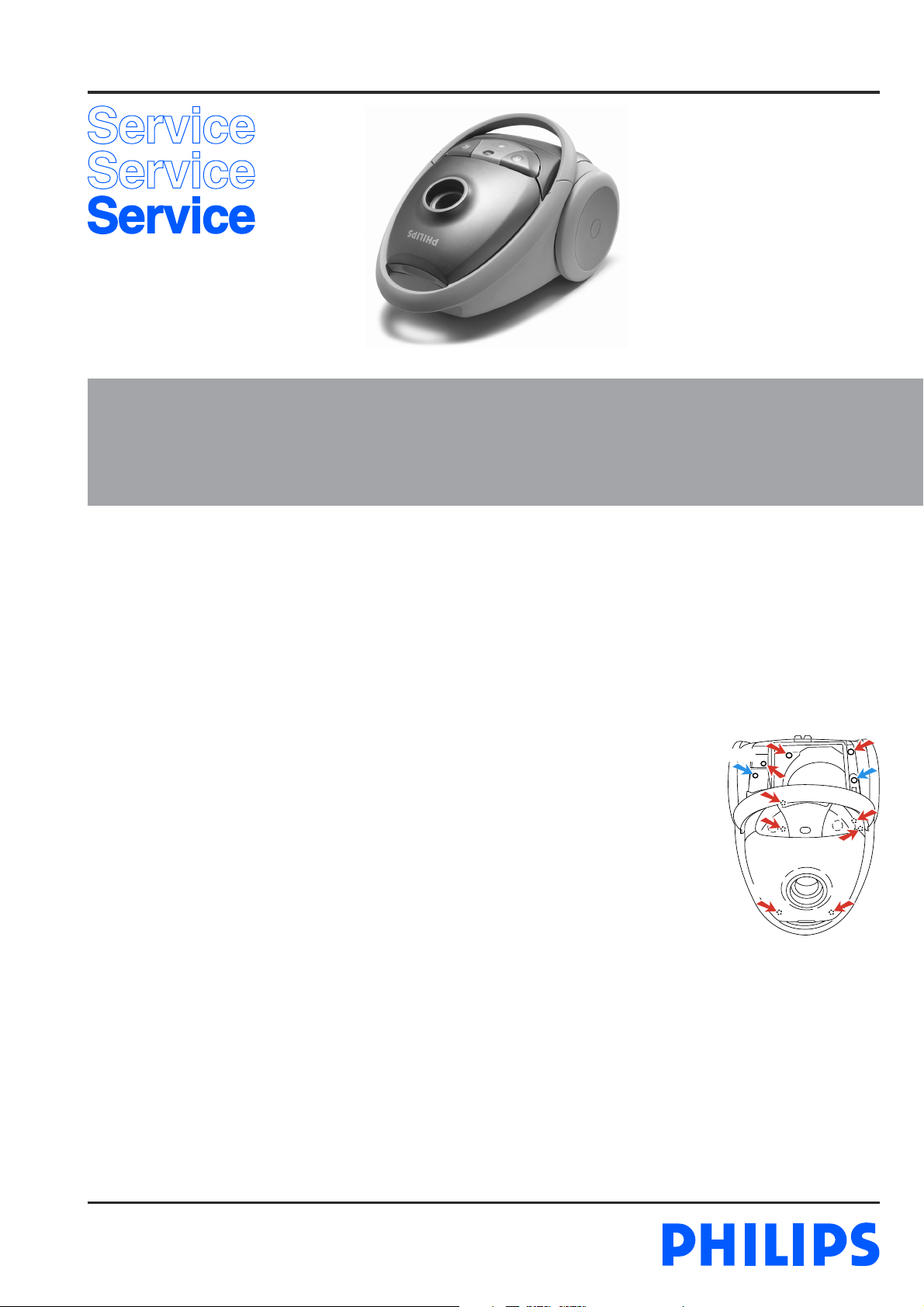
DISASSEMBLY- AND RE-ASSEMBLY ADVISE
- Open the appliance, first remove
the exhaust filter grille (item 20),
and then remove the 2 screws -
C of the switch control panel
(item 15).
- Undo and remove the 9 screws -
C in the upper housing (item 8).
You will require a screwdriver
with a 14.5 cm-long shank for
this. Depending on the version
screwdriver 9965 000 08332 for
cross head or onwards 0234
screwdriver 4322 009 08490 for T15 can be used.
- The component configuration shown in the exploded view
may differ in case of specific versions. The components are
distinguished by means of code numbers.
- When the repair is finished, check whether all functions of
the appliance work properly.
- To disassemble the cord winder, use TORX screwdriver no.
T10, which is one of a set consisting of T20; T15; T10; T9;
T8; T7 and T6 (code number 4822 395 50145).
C 2x
C 9x
Published by Philips Domestic Appliances and Personal Care Printed in the Netherlands © Copyright reserved Subject to modification
03/03
REPAIR INSTRUCTION
FC9114
- Item 4, cotton dustbag, is used in countries in which paper
dustbags are not available.
- If the reel half spring unit is replaced, shaft A must be
lubricated with silicone grease. Do not apply any silicone
grease to or spill any grease on terminals (43) or conductors
(42).
- Item 40 is provided with a long cord-winder spring, but
both long and short cords can be used in combination with
this spring. (L = 9.3 m)
- Depending on the original cord, the spare cord must be
shortened to the length of the original cord.
- The cord winder spring must be tensioned to the maximum
level and then be rewound approx. 1.5 turn
- Item 13, air valve, opens to cool the motor if the air
displacement is too low or if the airflow is blocked.
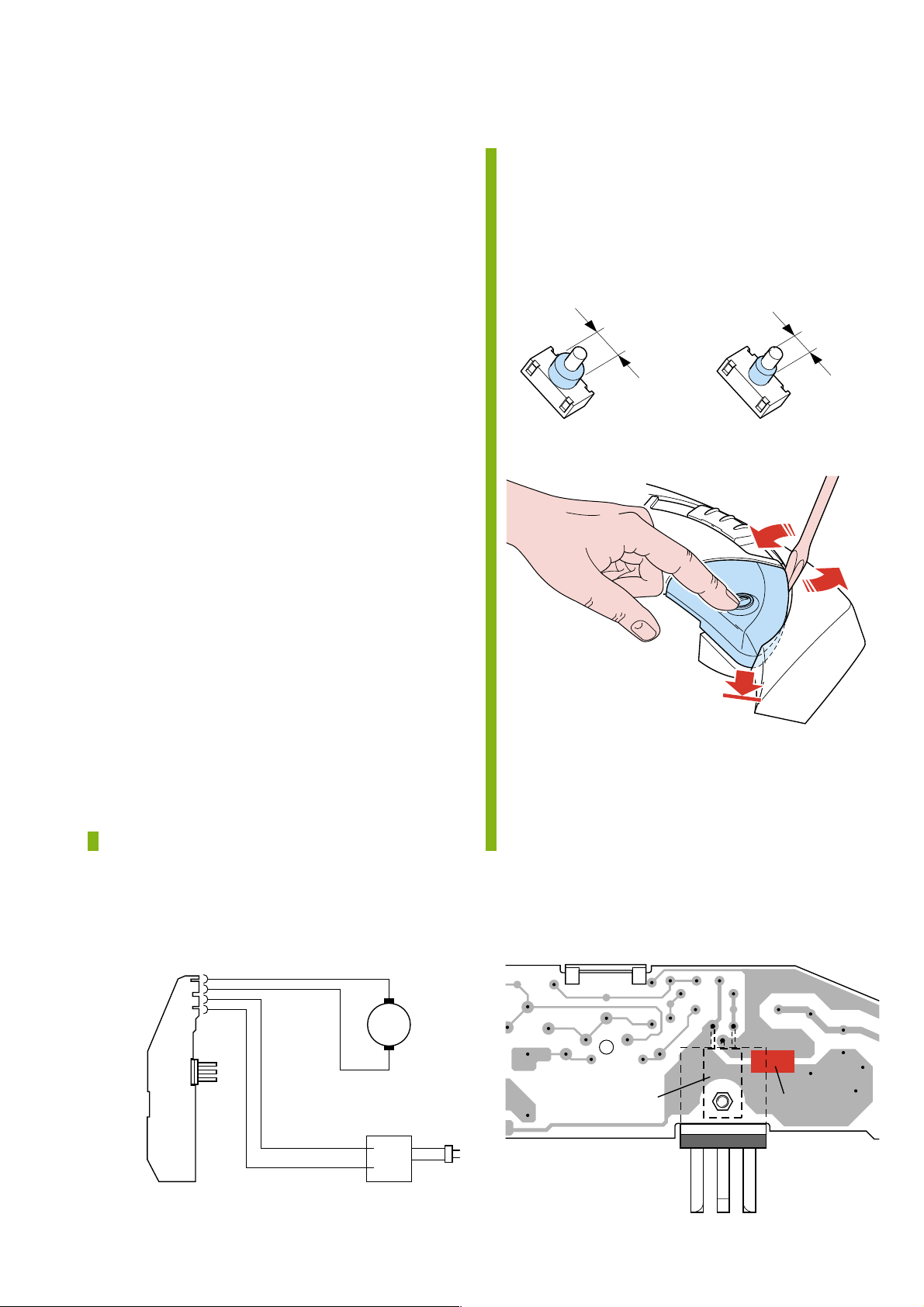
- To adjust the telescopic tube (item 59) to the required
length, push the adjustment collar in the direction of the
arrow while sliding the top section of the telescopic tube
into or out of the lower section.
- If the function of the electronic control unit (item 12) is
not required, the Triac must be short-circuited in the
manner shown in the circuit diagram.
- When the vacuum cleaner is used to suck up fine dust the
pores of the dustbag may become clogged, causing the
passage of air through the dustbag to become obstructed.
As a result, the dustbag-full indicator will indicate that the
dustbag needs to be replaced, eventhough the dustbag is not
full at all.
- Due to introduction of a new switch (item 11) 0320
onwards, which is not interchangable with the old switch
soldered on the PCB (item 12).
- The switch lever assy (item 11a) is also modified.
To recognize the switches:
Old New
∅ 13 mm
To replace the knobs:
∅ 10 mm
2
1
= changed
ELECTRICAL DIAGRAM
MOTOR
POWER
MODULE
Black
Black
Blue
Brown
M
CORD WINDER
New spares are:
11 Switch soldered version - 4322 006 50600
11a Switch lever assy - 4322 009 08980
parts of 15 Switch and Cord winder knob - 4322 009 09000
Triac
Short-circuit
2-7

PARTS LIST
FC9114
Pos Service code Description
1
4322 009 08130
2
4322 003 18280
3
4322 003 18150
4
4822 480 10113
4322 004 93290
5
4322 003 18300
6
4322 001 73310
7
4322 005 12550
8
4322 003 18050
8a
4322 003 20410
9
4322 000 37300
10
4322 009 07040
11
4322 006 21480
4322 006 50600
11a
4322 009 08420
4322 009 08980
12
4322 006 22560
13a
4322 005 12200
13b
4322 005 12210
14
4322 003 18090
15
4322 009 08200
16
4322 003 17890
17
4322 003 18100
18
4322 000 37450
19
4322 005 12180
20
4322 009 08260
21
4322 000 37460
22
4322 004 92910
23
4322 001 73280
24
4322 003 18000
25
4322 000 37420
26
4322 000 37430
27
4322 003 18070
28
4322 003 18910
29
4322 003 11990
30
4322 003 17990
31
4322 001 73300
32
4322 003 18040
33
4322 003 18010
34
4322 003 18020
Dust cover Mauve metallic
Dust cover lock grey
Dustbag holder
S-paper dustbags FC8021
Cotton dustbag
Cordwinder lever
Sealing rim
Dustbag detector
Upper housing l.grey
Clamp upper/lower housing
Triple fi lter
Grill + triple fi lter
Switch soldered version
Switch sold. vers. 0320 onwards
Switch lever assy
Switch lever assy 0320 onwards
PCB slide turn 230 V
Dustbag full indicator
Air valve
Handle l.grey
Panel slide Mauve metallic
Lower housing l.grey
Handle lock
Silencer 4 wall
Caster assy l.grey
Exhaust grille Mauve metallic
Exhaust diffusor
Electr.static fi lter FC8030
Filter sealing
S-class sealing
Silencer 1 wall
Silencer 2 bottom
Cord outlet l.grey
Rear wheel lock red
Receipt. housing A.C.
Rear wheel soft mauve
Motor buffer back
Inlet sealing
Motor cap top
ANS disc
Pos Service code Description
35
4322 001 73290
36
4322 009 06430
37
4322 000 37440
38
4322 003 18030
40
4322 009 07940
41
4322 001 72360
42
4322 009 07950
43
4322 009 07970
44
4322 006 01440
4322 006 01760
45
4322 006 01680
46
4322 006 01720
47
4322 006 01410
48
4322 006 01670
49
4322 006 01460
50
4322 003 18850
51
4322 005 12720
54
4322 007 16000
55
4322 004 22570
56
4322 003 18870
57
4322 005 12530
59
4322 004 22520
60
4322 001 99120
61
4322 007 45550
62
4322 004 22560
63
4322 004 22490
64
4322 004 22540
65
4322 005 11040
66
8838 041 01010
67
9965 000 03349
68
4822 358 10205
69
4822 479 20201
70
4322 004 22580
A
5322 390 20011
B
4322 002 82550
C
4322 002 82080
Motor bufferring front
Motor A 1441 230 V
Silencer 3 ans
Motor cap bottom
Reel half spring unit (L = 9m)
Brake tyre
Reel half contact unit
Contact ring plate
Argentina L = 9.3 m
Australia L = 9.3 m
Taiwan L = 6.3 m
U.K. / H.K. L = 9.3 m
Euro 4.8 mm pins L = 9.3 m
Swiss L = 9.3 m
Italy L = 9.3 m
C-bend B1
C-bend B1 hose sw assy
Leaf spring assy
Plumeau assy
Crevice nozzle
Acc. bridge assy
Telesc. tube act. coupling silver
Tube bush
Tube spring
Small nozzle
R&C nozzle standard l.grey
Polishing nozzle act. coupling
Polishing disc
Polishing brushes
Coupl. piece (standard)
Drive belt
Brush assy
Turbo nozzle act. coupling
Silicon grease for shaft
Screw 3.5 x 12 T10
Screw 3.5 x 19
= changed
3-7
 Loading...