


Philips FC9009 Service Manual
Universe Vacuum cleaner
FC9009
Philips Domestic Appliances and Personal Care
Service Manual
PRODUCT INFORMATION
- This product meets the requirements regarding
interference suppression on radio and TV.
- After the product has been repaired, it should function
properly and has to meet the safety requirements as
officially laid down at this moment.
TECHNICAL INFORMATION
- Colour : Soft red
- Maximum air displacement : 37 l/sec.
- Maximum vacuum water column : 310 cm
- Power consumption (IEC) 230 V : 1400 W
- Duststorage capacity : 3 L
- Type number dustbag : FC8021
- Cord length (depends on version) : 7 metres
- Filter system : Paper dustbag
: Exhaust AFS air filter
: Motor inlet filter
- Dimensions of cleaner : 460 x 315 x 270 mm
- Dimensions of packaging : 595 x 395 x 295 mm
- Net weight : 5.88 kg
- Gross weight : 9.135 kg
OPTIONAL (accessories)
- FC8021 S-bags
- FC8030 AFS-filter
- FC8031 HEPA Air Filter
- FC8034 Upgrate kit Active Carbon Filter
- HR6988 Turbo brush nozzle
- HR8040 Polishing nozzle
- HR6943 Hard floor nozzle
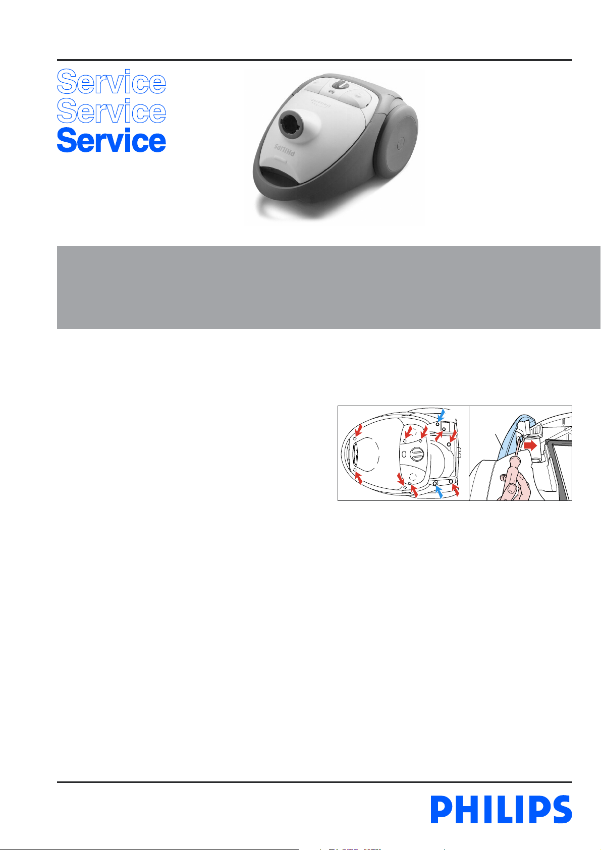
DISASSEMBLY- AND RE-ASSEMBLY ADVISE
- Open the appliance, first remove the exhaust filter grille
(item 20), and then remove the 2 screws - C of the switch
control panel (item 15).
C 2x
C 9x
- To remove the the panel, pos 14a + b must be removed by
using a screwdriver to separate the two covers from the panel
as shown in the picture.
- Undo and remove the 9 screws - C in the upper housing
(item 8). You will require a screwdriver with a 14.5 cm-long
shank for this. Srewdriver 9965 000 08332 can be used.
- The component configuration shown in the exploded view
may differ in case of specific versions. The components are
distinguished by means of code numbers.
- When the repair is finished, check whether all functions of
the appliance work properly.
- To disassemble the cord winder, use TORX screwdriver no.
T10, which is one of a set consisting of T20; T15; T10; T9;
T8; T7 and T6 (code number 4822 395 50145).
14a + b
Published by Philips Domestic Appliances and Personal Care Printed in the Netherlands © Copyright reserved Subject to modification
03/03
REPAIR INSTRUCTION
- Item 4, cotton dustbag, is used in countries in which paper
dustbags are not available.
- If the reel half spring unit is replaced, shaft A must be
lubricated with silicone grease. Do not apply any silicone
grease to or spill any grease on terminals (43) or conductors
(42).
- Item 40 is provided with a long cord-winder spring, but
both long and short cords can be used in combination with
this spring. (L = 9.3 m)
- Depending on the original cord, the spare cord must be
shortened to the length of the original cord.
- The cord winder spring must be tensioned to the maximum
level and then be rewound approx. 1.5 turn
- Item 13, air valve, opens to cool the motor if the air
displacement is too low or if the airflow is blocked.
- If the function of the electronic control unit (item 12) is
not required, the Triac must be short-circuited in the
manner shown in the circuit diagram.
- When the vacuum cleaner is used to suck up fine dust the
pores of the dustbag may become clogged, causing the
passage of air through the dustbag to become obstructed.
As a result, the dustbag-full indicator will indicate that the
dustbag needs to be replaced, eventhough the dustbag is not
full at all.
FC9009
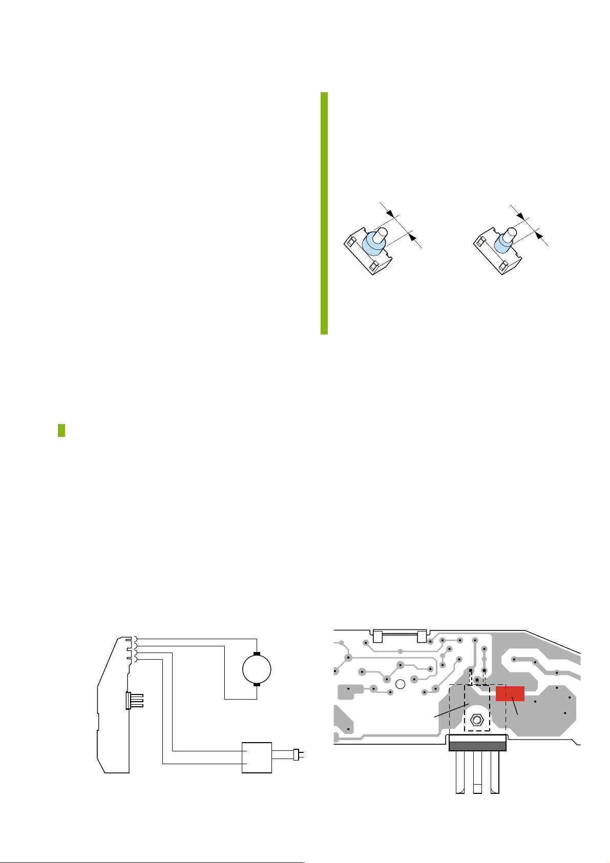
- Due to introduction of a new switch (item 11) 0320
onwards, which is not interchangable with the old switch
soldered on the PCB (item 12).
- The switch lever assy (item 11a) is also modified.
To recognize the switches:
Old New
∅ 13 mm
New spares are:
Switch soldered version - 4322 006 50600
Switch lever assy - 4322 009 08980
∅ 10 mm
= changed
ELECTRICAL DIAGRAM
MOTOR
POWER
MODULE
Black
Black
Blue
Brown
M
CORD WINDER
Triac
Short-circuit
2-6
 Loading...