


 Loading...
Service Manual
Verification Draft
29 June 2000
M4735A Defibrillator/Monitor

Notice
About This Edition
Edition 1
Printed in the USA
Publication number M4735-90900
The information in this manual applies to the M4735A Heartstream XL Release A.0.0. This information is subject to change without notice.
Agilent Technologies shall not be liable for errors contained herein or for incidental or consequential damages in connection with the furnishing, performance, or use of this material.
Edition History
Edition 1, July, 2000
Copyright
Copyright © 2000
Agilent Technologies, Inc.
3000 Minuteman Road
Andover, MA 01810-1099 USA
(978) 687-1501
This document may not be photocopied, reproduced, or translated to another language without prior written consent of Agilent Technologies.
WARNING
Radio Frequency (RF) interference from nearby transmitting devices may seriously degrade performance of the M4735A. Electromagnetic compatibility with surrounding devices should be assessed prior to using the defibrillator.
CAUTION
Use of supplies or accessories other than those recommended by Agilent Technologies may compromise product performance.
THIS PRODUCT IS NOT INTENDED FOR HOME USE.
IN THE U.S., FEDERAL LAW RESTRICTS THIS DEVICE TO SALE ON OR BY THE ORDER OF A PHYSICIAN.
Medical Device Directive
The M4735A Defibrillator/Monitor complies with the requirements of the Medical Device Directive 93/42/EEC
and carries the 
 0123 mark accordingly.
Authorized EU-representative:
Agilent Technologies GmbH
Herrenbergerstrasse 130
D-71034 Boeblingen,
Germany
Fax: +49-7031-14-2346
ii

Conventions
NOTE
CAUTION
WARNING
This manual uses the following text conventions:
Printed and On-Line
Notes contain additional information on servicing this product.
Caution statements describe conditions or actions that can result in damage to the equipment or loss of data.
Warning statements describe conditions or actions that can result in personal injury or loss of life.
Text |
represents messages that appear on the display |
|
|
|
represents softkey labels that appear on the display |
|
Softkey |
|
|
above or below the button to which they correspond |
|
On-Line Only
Hypertext represent hypertext links, which will display as blue; click on the link to go to that destination, then click on the destination to return.
iii

This page intentionally left blank
iv

Contents
Conventions
Printed and On-Line .......................................................................................................... |
iii |
On-Line Only ................................................................................................................. |
iii |
Hypertext .......................................................................................................................... |
iii |
Introduction
Overview .................................................................................................................... |
1-1 |
Defibrillator/Monitor ...................................................................................................... |
1-1 |
Batteries .......................................................................................................................... |
1-2 |
Installation ...................................................................................................................... |
1-2 |
Upgrades ......................................................................................................................... |
1-2 |
Preventive Maintenance .................................................................................................. |
1-2 |
Repair Philosophy ........................................................................................................... |
1-3 |
Performance Verification and Safety Tests
Overview ......................................................................................................................... |
2-1 |
Chapter Contents ............................................................................................................. |
2-1 |
Mandatory Testing ...................................................................................................... |
2-2 |
External Repairs/No Trouble Found ............................................................................... |
2-2 |
Printer .............................................................................................................................. |
2-3 |
Internal Repairs ............................................................................................................... |
2-3 |
Test Matrix ................................................................................................................. |
2-4 |
Test Equipment ........................................................................................................... |
2-8 |
Configuration and Diagnostic Modes ...................................................................... |
2-10 |
Configuration Mode ...................................................................................................... |
2-10 |
Diagnostic Mode ........................................................................................................... |
2-11 |
The Software Support Tool ...................................................................................... |
2-12 |
Using the Support Tool ................................................................................................. |
2-12 |
Performance Verification ......................................................................................... |
2-14 |
Visual Inspection ........................................................................................................... |
2-15 |
Functional Checks ......................................................................................................... |
2-16 |
Diagnostic Tests ............................................................................................................ |
2-19 |
Safety Tests .................................................................................................................. |
2-39 |
Battery Capacity Test .................................................................................................... |
2-40 |
v 6/29/00

Contents
Troubleshooting
Overview ......................................................................................................................... |
3-1 |
Chapter Contents ............................................................................................................. |
3-1 |
Repair Philosophy ........................................................................................................... |
3-1 |
Equipment Required ....................................................................................................... |
3-1 |
Troubleshooting and Repair Methodology ................................................................ |
3-2 |
Methodology Overview .................................................................................................. |
3-2 |
Initial Assessment ...................................................................................................... |
3-3 |
Diagnosing External Failures ..................................................................................... |
3-4 |
Diagnosing Internal Failures ...................................................................................... |
3-5 |
Troubleshooting Tables .............................................................................................. |
3-6 |
Using the Tables ............................................................................................................. |
3-6 |
General Problems ....................................................................................................... |
3-8 |
Unit Unresponsive .......................................................................................................... |
3-8 |
Error Codes ................................................................................................................... |
3-10 |
System Messages .......................................................................................................... |
3-12 |
Momentary Messages ................................................................................................... |
3-14 |
Audio Tones ................................................................................................................ |
3-16 |
Extended Self Test Failures .......................................................................................... |
3-17 |
Operational Problems ............................................................................................... |
3-18 |
ECG Monitoring ......................................................................................................... |
3-18 |
SpO2 Monitoring .......................................................................................................... |
3-20 |
Defibrillation and Cardioversion ................................................................................. |
3-21 |
Pacing ............................................................................................................................ |
3-24 |
Printer ........................................................................................................................... |
3-25 |
Display .......................................................................................................................... |
3-26 |
Audio ............................................................................................................................ |
3-27 |
Keys ............................................................................................................................. |
3-28 |
Battery and Charging Circuits ...................................................................................... |
3-29 |
Data Card ...................................................................................................................... |
3-30 |
Calling for Service ................................................................................................... |
3-31 |
United States of America .............................................................................................. |
3-31 |
Canada .......................................................................................................................... |
3-31 |
Other International Areas .............................................................................................. |
3-31 |
Equipment Information ................................................................................................. |
3-31 |
Removal and Replacement
Overview ......................................................................................................................... |
4-1 |
Chapter Contents ............................................................................................................. |
4-1 |
Servicing Notes .......................................................................................................... |
4-1 |
Key Components ............................................................................................................. |
4-1 |
Removal, Handling, and Replacement ........................................................................... |
4-2 |
Tool Requirements .......................................................................................................... |
4-3 |
vi

|
Contents |
Disposal .......................................................................................................................... |
4-3 |
External Assemblies ................................................................................................... |
4-4 |
User-replaceable Parts and Accessories .......................................................................... |
4-5 |
User Maintenance ........................................................................................................... |
4-5 |
Printer Assembly ............................................................................................................. |
4-6 |
Battery Cover ................................................................................................................ |
4-10 |
Main Fuse ..................................................................................................................... |
4-12 |
Battery Eject Assembly ................................................................................................ |
4-14 |
Data Card Door ............................................................................................................. |
4-16 |
Energy Select Knob .................................................................................................... |
4-17 |
Paddle Holders .............................................................................................................. |
4-18 |
Labels ............................................................................................................................ |
4-20 |
Label Descriptions ........................................................................................................ |
4-20 |
Removing and Replacing Labels .................................................................................. |
4-22 |
Opening the Case ..................................................................................................... |
4-24 |
Discharge the Power Supply Capacitors ...................................................................... |
4-24 |
Separate the Case ........................................................................................................ |
4-26 |
Discharge the Defibrillator Capacitor .......................................................................... |
4-30 |
Identifying Internal Subassemblies ............................................................................... |
4-32 |
Internal Assemblies - Top Case ................................................................................ |
4-33 |
Lithium Backup Battery ................................................................................................ |
4-34 |
Control PCA ................................................................................................................ |
4-36 |
Shield Plate ................................................................................................................... |
4-40 |
Keyscan PCA ................................................................................................................ |
4-42 |
Bezel Assembly .......................................................................................................... |
4-48 |
Energy Select Switch .................................................................................................... |
4-52 |
...................................................................................................................................... |
4-53 |
Display Assembly ......................................................................................................... |
4-54 |
Parameter PCA ............................................................................................................. |
4-56 |
SpO2 PCA .................................................................................................................. |
4-58 |
ECG Connector ............................................................................................................. |
4-60 |
SpO2 Connector ............................................................................................................ |
4-62 |
Speaker ....................................................................................................................... |
4-64 |
AC Mains Connector .................................................................................................... |
4-66 |
ECG Out (Sync) Connector .......................................................................................... |
4-69 |
Pacer Keypad ................................................................................................................ |
4-70 |
Replacement Top Case .................................................................................................. |
4-75 |
Internal Assemblies - Bottom Case .......................................................................... |
4-79 |
Battery PCA .................................................................................................................. |
4-80 |
Defibrillator Capacitor .................................................................................................. |
4-84 |
Power PCA ................................................................................................................... |
4-86 |
AC Power Module ........................................................................................................ |
4-90 |
Patient Connector .......................................................................................................... |
4-94 |
Replacement Bottom Case ............................................................................................ |
4-97 |
Closing the Case ....................................................................................................... |
4-99 |
vii

Contents
Replacement Parts
Overview ......................................................................................................................... |
5-1 |
Chapter Contents ............................................................................................................. |
5-1 |
Ordering Replacement Parts .......................................................................................... |
5-1 |
Ordering Supplies and Accessories ................................................................................ |
5-1 |
Key Components ........................................................................................................... |
5-2 |
Calling for Service ..................................................................................................... |
5-3 |
United States of America ........................................................................................... |
5-3 |
Canada ........................................................................................................................ |
5-3 |
Other International Areas ............................................................................................ |
5-3 |
Special Tools .............................................................................................................. |
5-4 |
M4735A Unit Exchange Program .............................................................................. |
5-5 |
Replacement Parts Tables ........................................................................................... |
5-6 |
Electrical Assemblies ................................................................................................. |
5-7 |
Control PCA ................................................................................................................... |
5-7 |
Other Replacement PCAs ............................................................................................... |
5-8 |
Other Electrical Assemblies ........................................................................................... |
5-8 |
Individual Electrical Parts ............................................................................................... |
5-9 |
Mechanical Assemblies ............................................................................................ |
5-10 |
Bezel Assembly ............................................................................................................ |
5-10 |
Pacer Keypad Assembly ............................................................................................... |
5-11 |
Other Mechanical Assemblies ...................................................................................... |
5-12 |
Connector Assemblies .................................................................................................. |
5-12 |
Individual Mechanical Parts ......................................................................................... |
5-13 |
Labels ....................................................................................................................... |
5-14 |
Instruction Label Sets ................................................................................................... |
5-14 |
Case Label Sets ............................................................................................................. |
5-16 |
Other Labels ................................................................................................................. |
5-17 |
Supplies & Accessories ............................................................................................ |
5-18 |
Key Components ...................................................................................................... |
5-21 |
Theory of Operation
Overview ......................................................................................................................... |
6-1 |
PCA Descriptions ....................................................................................................... |
6-2 |
Control PCA ................................................................................................................... |
6-2 |
Power PCA ..................................................................................................................... |
6-3 |
Parameter PCA ............................................................................................................... |
6-3 |
Keyscan PCA .................................................................................................................. |
6-3 |
SpO2 PCA ....................................................................................................................... |
6-4 |
Battery PCA .................................................................................................................... |
6-4 |
Battery ............................................................................................................................. |
6-4 |
AC Power Module .......................................................................................................... |
6-4 |
Printer .............................................................................................................................. |
6-4 |
viii

|
Contents |
System Level Interconnections .................................................................................. |
6-5 |
System Functional Descriptions ................................................................................. |
6-6 |
Signal and Data Flow ...................................................................................................... |
6-6 |
ECG Monitoring Functions ............................................................................................ |
6-7 |
Patient impedance functions ........................................................................................... |
6-7 |
SpO2 Monitoring Functions ........................................................................................... |
6-8 |
Defibrillation Functions .................................................................................................. |
6-9 |
Pacing Functions ........................................................................................................... |
6-11 |
Audio Functions ............................................................................................................ |
6-11 |
Display Functions ......................................................................................................... |
6-11 |
Indicator Functions ....................................................................................................... |
6-11 |
Key Functions ............................................................................................................... |
6-11 |
Energy Select Switch .................................................................................................... |
6-12 |
Printing Functions ......................................................................................................... |
6-12 |
Battery/Power Functions ............................................................................................... |
6-12 |
Lithium Backup Battery ................................................................................................ |
6-15 |
Data Card ...................................................................................................................... |
6-15 |
Specifications |
|
Overview ......................................................................................................................... |
7-1 |
Specifications ............................................................................................................. |
7-1 |
Defibrillator .................................................................................................................... |
7-1 |
ECG Monitoring ............................................................................................................. |
7-3 |
Display ............................................................................................................................ |
7-4 |
Battery ............................................................................................................................. |
7-4 |
Thermal Array Printer ..................................................................................................... |
7-5 |
Noninvasive Pacing ........................................................................................................ |
7-6 |
SpO2/Pulse Oximetry ...................................................................................................... |
7-6 |
Event Storage .................................................................................................................. |
7-6 |
General ............................................................................................................................ |
7-7 |
Environmental ................................................................................................................. |
7-7 |
Waveforms - 150J ...................................................................................................... |
7-8 |
Waveforms - 200J ................................................................................................. |
7-11 |
Symbol Definitions .................................................................................................. |
7-14 |
Safety Considerations ............................................................................................... |
7-16 |
Electromagnetic Compatibility ................................................................................ |
7-19 |
Reducing Electromagnetic Interference ........................................................................ |
7-19 |
Restrictions for Use ...................................................................................................... |
7-20 |
Immunity Level ............................................................................................................. |
7-20 |
ix

Contents
This page intentionally left blank.
x
1 |
Introduction |
|
||||
1 |
||||||
|
This Service Manual provides the information needed to successfully service the Agi- |
|||||
|
lent M4735A Heartstream XL Defibrillator/Monitors. The intended users of this man- |
|
||||
|
ual are technical personnel who have been trained in the safe and proper servicing of |
|
||||
|
the M4735A. |
|
||||
|
|
|||||
|
|
|
|
|
|
|
|
|
|
Overview |
|
||
|
|
|
|
|||
|
|
|
In this chapter, you’ll find general information that you should become famil- |
|
||
|
|
|
iar with before servicing the M4735A. Detailed information regarding con- |
|
||
|
|
|
trols, operation, and capabilities of the instrument can be found in the User’s |
|
||
|
|
|
Guide (M4735-91900) that was shipped with the product. We recommend |
|
||
|
|
|
you review the User’s Guide before servicing this device. This Service Man- |
|
||
|
|
|
ual assumes you are familiar with the controls and with basic operations. |
|
||
|
|
|
Defibrillator/Monitor |
|
||
|
|
|
The M4735A is a biphasic, semi-automatic external defibrillator. This porta- |
|
||
|
|
|
ble, lightweight device offers two modes of operation for defibrillation: |
|
||
|
|
|
l Semi-Automatic External Defibrillation (AED) Mode |
|
||
|
|
|
l Manual Mode |
|
||
|
|
|
In AED Mode, the M4735A analyzes the patient’s ECG and advises the clini- |
|
||
|
|
|
cian whether or not to deliver a shock. Defibrillation is performed through |
|
||
|
|
|
multifunction defib electrode pads. |
|
||
|
|
|
In Manual Mode, the M4735A turns control of the defibrillation process over |
|
||
|
|
|
to the clinician. The clinician analyzes the patient’s ECG, decides if defibrilla- |
|
||
|
|
|
tion is advised, and determines the energy setting for defibrillation. Defibrilla- |
|
||
|
|
|
tion is performed either through multifunction defib electrode pads or through |
|
||
|
|
|
paddles. |
|
||
|
|
|
Manual Mode also allows the clinician to perform synchronized cardioversion |
|
||
|
|
|
and offers optional noninvasive pacing (using a monophasic waveform). |
|
||
|
|
|
ECG monitoring can be accomplished in either mode using one of 3 methods: |
|
||
|
|
|
l ECG from the defib pads |
|
||
|
|
|
l 3-lead ECG using separate monitoring electrodes |
|
||
|
|
|
l Optional 5-lead ECG using separate monitoring electrodes. |
|
||
|
|
|
Optional pulse oximetry (SpO2) monitoring is available in both modes, as |
|
||
|
|
|
well. |
|
||
|
|
|
The M4735A automatically stores critical events, such as shocks and alarm |
|
||
|
|
|
violations, in its internal memory. An Event Summary may be printed at any |
|
||
|
|
|
time. The M4735A also enables you to store data and events on an M3510A |
|
||
1-1
6/29/00

Overview
Data Card for downloading to the CodeRunner Web Data Management System.
|
|
Batteries |
|
|
The M4735A is powered by a rechargeable Sealed Lead Acid (SLA) battery |
|
|
(M3516A). Proper care of these batteries will ensure that they have the |
|
|
energy required to operate the M4735A and deliver the appropriate therapy |
|
|
(See "Battery Maintenance" section in User’s Guide). |
|
|
|
|
|
|
|
|
|
NOTE |
|
The defibrillator will take longer to charge when powered with AC without a |
|
|
battery installed. To ensure optimal performance, always have a fully charged |
|
||
|
||
|
|
battery in the defibrillator, even when using AC power. |
|
|
|
Installation
The M4735A does not require installation. The User’s Guide describes the setup required before placing the device into service, as well as configuration options.
Upgrades
Upgrades are available to add specific functionality to units in the field. As of the publication of this manual, these upgrades are:
l M4738A Pacing Upgrade (adds pacing). l M4739A SpO2 upgrade. (adds SpO2).
Consult your sales representative or dealer or distributor for the latest details.
Preventive Maintenance
Preventive maintenance and periodic operational checks are intended to be performed by the user. Both topics are covered in the Maintenance chapter of the User’s Guide.
1-2 |
Introduction |

Overview
|
|
Repair Philosophy |
|
||
|
|
||||
|
|
Defibrillator/Monitor |
1 |
||
|
|
The repair philosophy of the M4735A is subassembly replacement. Examples |
|||
|
|
of subassemblies are the printer, the Control Printed Circuit Assembly (PCA), |
|
||
|
|
and selected connectors and other items. Repairs that involve replacing com- |
|
||
|
|
ponents on a PCA are not supported. |
|
||
|
|
||||
|
|
|
|
|
|
|
|
|
|
|
|
|
|
|
|
|
|
CAUTION |
|
Individual component replacement should not be attempted outside of a fac- |
|
||
|
|
tory authorized repair facility. Component level repair is extremely difficult |
|
||
|
|
||||
|
|
||||
due to the extensive use of surface mount technology and the high parts-den- sity on the circuit boards. Unauthorized component replacement can impair performance of the M4735A.
Batteries
The repair philosophy for the SLA battery (M3516A) is unit replacement.
These items are not repaired in the field.
For information on ordering replacements, see "Supplies & Accessories" on page 5-18.
M4735A Service Manual |
1-3 |

Overview
This page intentionally left blank.
1-4 |
Introduction |

2 Performance Verification and Safety Tests
Overview |
2 |
|
This chapter describes the tests and inspections required to verify perfor- |
||
|
||
mance of the M4735A Portable Defibrillator/Monitor. |
|
|
Chapter Contents |
|
|
|
||
The major sections of this chapter are as follows: |
|
Section |
Page |
Mandatory Testing |
2-2 |
Test Matrix |
2-4 |
Test Equipment |
2-8 |
Configuration and Diagnostic Modes |
2-10 |
The Software Support Tool |
2-12 |
Performance Verification |
2-14 |
2-1
6/29/00

Mandatory Testing
Mandatory Testing
The Performance Verification Tests in this chapter are intended to verify proper operation of the M4735A following repair. The level of testing required corresponds to the type of repair performed, and is divided into 3 categories: External/No Trouble Found, Printer Replacement, and Internal Repairs. Each of these categories is described below.
External Repairs/No Trouble Found
External Repairs are those involving the repair or replacement of one or more of the items below. No Trouble Found applies when no malfunction can be found, or when the problem appears to be due to improper use. In either situation, the key point is that the case has not been opened.
lExternal paddles
lInternal paddles and/or adapter cable
lPaddle holders
lPads adapter cable
lECG cable
lSpO2 cable or sensor
lBattery
lLabels
lAC Power cord
lConsumables (ECG monitoring electrodes, multifunction defibrillation pads, printer paper)
lMain fuse (on Battery PCA)
lData Card Door Assembly
lBattery Eject Assembly
The following testing is required after an External Repair or when the outcome of the service is No Trouble Found (when the case has not been opened):
lPerform the Visual Inspection (page 2-15).
lRun the Extended Self Test (page 2-22).
lPrint and Verify the System Log (page 2-20).
2-2 |
Performance Verification and Safety Tests |

Mandatory Testing
Printer
If the printer was replaced, and the case was not opened, the following tests are required:
lPerform the Visual Inspection (page 2-15).
lRun the Extended Self Test (page 2-22).
lRun the Printer Test (page 2-27).
lPrint and Verify the System Log (page 2-20).
2
Internal Repairs
If the case was opened (regardless of what the repair involved), all of the Performance Verification Tests must be performed, beginning with "Visual Inspection" on page 2-15.
M4735A Service Manual |
2-3 |

Test Matrix
Test Matrix
The matrix in Table 2-1 summarizes performance verification tests and inspections for the M4735A; including test name, test or inspection to perform, expected test results, and data to record.
Table 2-1 Performance Verification and Safety Tests
Test Group Name |
Test or Inspection to |
Expected Test Results |
Data to Record |
|
Perform |
x = p (pass) or f(fail) |
|||
|
|
|||
|
|
|
|
|
Visual Inspection |
Inspect unit, accessories, |
• No unusual damage, no |
V:x |
|
(V) |
cables, etc. as described |
corrosion: x=p. |
Example V:p |
|
|
on page 2-15. |
|
|
|
|
|
|
|
|
Functional |
In normal Operating Mode, |
• All functions respond as |
F:x |
|
Checks (F) |
perform the following func- |
expected |
Example F:p |
|
|
tional checks: |
|
|
|
|
• ECG (page 2-16). |
• Waveform clear on display; |
|
|
|
|
|||
|
|
HR correct on display; HR |
|
|
|
|
alarm works |
|
|
|
• Shock Advisory (page 2- |
• Shock Advised only when |
|
|
|
17). |
appropriate |
|
|
|
• Synchronized Cardiover- |
• Shock delivered with cor- |
|
|
|
sion (page 2-18). |
rect timing |
|
|
|
• SpO2 (page 2-18). |
• 95% -100% |
|
|
|
|
|
|
|
Extended Self |
In Diagnostic Mode, run |
"Pass" reported on all tests |
X:x |
|
Test (X) |
the Extended Self Test |
applicable to the device con- |
Example X:p |
|
|
(page 2-22). Includes Data |
figuration and options: x=p. |
|
|
|
Card Test and time/date |
|
|
|
|
check. |
|
|
|
|
|
|
|
|
User Interface |
• In Diagnostic Mode, run |
All responses as expected. |
U:x |
|
Tests (U) |
the following tests (page |
|
Example: U:p |
|
|
2-25): |
|
|
|
|
• Controls Test |
• All keys respond as |
|
|
|
|
expected |
|
|
|
• Display Test |
• Visual Pass assessment by |
|
|
|
|
service personnel |
|
|
|
• Audio Test |
• Audio Pass assessment by |
|
|
|
|
service personnel. |
|
|
|
• Printer Test |
• Print quality: visual Pass |
|
|
|
|
assessment by service per- |
|
|
|
|
sonnel |
|
|
|
|
• Print speed: 25 mm ± 5% |
|
|
|
|
(1.25mm) |
|
|
|
|
|
|
2-4 |
Performance Verification and Safety Tests |

|
|
|
Test Matrix |
||
Table 2-1 Performance Verification and Safety Tests |
|
|
|
||
|
|
|
|
|
|
Test Group Name |
Test or Inspection to |
Expected Test Results |
Data to Record |
|
|
Perform |
x = p (pass) or f(fail) |
|
|
||
|
|
|
|||
|
|
|
|
|
|
ECG Tests (E) |
In Diagnostic Mode, run |
All data within limits, all |
E: aaaa,bbbb,cc,dd, |
|
|
|
the ECG Tests (page 2-29): |
checks pass: x=p |
ee,ffff,x |
|
|
|
|
|
Example: |
|
|
|
|
|
E:1000,1000,20,20, |
|
|
|
• Status messages (lead, |
• "Good" displayed for all |
50,2000,p |
|
|
|
2 |
||||
|
|||||
|
|
|
|||
|
pad, DSP) |
three |
|
|
|
|
• DC offset |
• Ignore - used only in fac- |
|
|
|
|
|
|
|
||
|
|
tory manufacturing. |
|
|
|
|
Amplifier gain |
|
|
|
|
|
|
|
|
|
|
|
• Pads Peak to Peak (Moni- |
• 1000mV ±10% |
|
|
|
|
tor) - aaaa |
|
|
|
|
|
• Leads Peak to Peak (Diag- |
• 1000mV ±10% |
|
|
|
|
nostic) - bbbb |
|
|
|
|
|
Amplifier noise |
|
|
|
|
|
• Leads Peak to Peak (Diag- |
• 0 ± 30uV |
|
|
|
|
nostic) - cc |
|
|
|
|
|
• Pads Peak to Peak (Moni- |
• 0 ± 30uV |
|
|
|
|
tor) - dd |
|
|
|
|
|
PCI measurement |
|
|
|
|
|
• PCI - Paddles in Pockets – |
• 50 ± 30 Ω |
|
|
|
|
ee |
|
|
|
|
|
• PCI - Paddles open – ffff |
• > 1250 Ω |
|
|
|
|
|
|
|
|
|
Pacing Test (P) |
In Diagnostic Mode, run |
|
P:aa,bbb |
|
|
|
the Pacing Test (page 2- |
|
Example: P:31,198 |
|
|
|
33): |
|
|
|
|
|
• 30 mA – aa |
• 30 mA ± 5 mA |
|
|
|
|
• 200mA – bbb |
• 200mA± 20 mA |
|
|
|
|
|
|
|
|
|
M4735A Service Manual |
2-5 |

Test Matrix
Table 2-1 Performance Verification and Safety Tests
Test Group Name |
Test or Inspection to |
Expected Test Results |
Data to Record |
|
Perform |
x = p (pass) or f(fail) |
|||
|
|
|||
|
|
|
|
|
Defibrillator Test - |
Using only AC power, |
|
DA:aaa,bbbbb,ccc,dd |
|
AC Power (DA) |
enter Diagnostic Mode |
|
Example: |
|
(if AC Power used |
and run the Defibrillator |
|
DA:198,13000,195,48 |
|
in normal opera- |
Test (AC Power at 200J) |
|
|
|
tion) |
(page 2-35): |
|
|
|
|
Measured by |
|
|
|
|
Defibrillator Analyzer: |
|
|
|
|
• Delivered energy - aaa |
• 200 ± 30J |
|
|
|
Displayed by |
|
|
|
|
M4735A: |
|
|
|
|
• Available Energy after |
• 0 |
|
|
|
Shock |
|
|
|
|
• Msec to charge – bbbbb |
• < 15000 msec |
|
|
|
• Delivered energy - ccc |
• Actual delivered energy |
|
|
|
|
(aaa) ±7% |
|
|
|
• Impedance - dd |
• 42 to 57 Ω |
|
|
|
• Defib errors |
• None (0) |
|
|
|
|
|
|
|
Defibrillator Test - |
Using only battery power, |
|
DB:aaa,bbbb,ccc,dd |
|
Battery Power |
enter Diagnostic Mode |
|
Example: |
|
(DB) |
and run the Defibrillator |
|
DB:198,2545,200,50 |
|
|
Test (Battery Power at |
|
|
|
|
200J) (page 2-36). |
|
|
|
|
Measured by |
|
|
|
|
Defibrillator Analyzer |
|
|
|
|
• Delivered energy - aaa |
• 200 ± 30 J |
|
|
|
Displayed by |
|
|
|
|
M4735A |
|
|
|
|
• Available Energy after |
• 0 |
|
|
|
Shock |
|
|
|
|
• Msec to charge – bbbb |
• < 3000 msec |
|
|
|
• Delivered energy - ccc |
• Actual delivered energy |
|
|
|
|
(aaa) ±7% |
|
|
|
• Impedance - dd |
• 42 to 57 Ω |
|
|
|
• Defib errors |
• None (0) |
|
|
|
|
|
|
|
Defibrillator Dis- |
Enter Diagnostic Mode |
All readings as expected: |
D:x |
|
arm Test (D) |
and run the Defibrillator |
x=p |
Example: D:p |
|
|
Disarm Test (page 2-38) |
|
|
|
|
|
|
|
2-6 |
Performance Verification and Safety Tests |
|
|
|
Test Matrix |
||
Table 2-1 Performance Verification and Safety Tests |
|
|
|
||
|
|
|
|
|
|
Test Group Name |
Test or Inspection to |
Expected Test Results |
Data to Record |
|
|
Perform |
x = p (pass) or f(fail) |
|
|
||
|
|
|
|||
|
|
|
|
|
|
Safety Test (S) |
Test both leads and pads, |
|
S:aaa,bbbb, |
||
|
and indicate test results |
|
t,ccc,ddd,eeee,fff,ggg; |
||
|
as follows: |
|
t,ccc,ddd,eeee,fff,ggg |
||
|
External Leads: t=C |
|
Example: S:125,150, |
||
|
External Pads: t=B |
|
C,10,40,40,10,40; |
|
|
|
|
|
B,90,150,2500,90,250 |
|
|
|
Earth Leakage |
|
|
|
2 |
|
Earth Leakage |
< 500 uA (< 300 uA UL) |
|
|
|
|
|
|
|
||
|
(Normal Condition) - aaa |
|
|
|
|
|
Earth Leakage |
< 1000 uA |
|
|
|
|
|
|
|
||
|
(Single Fault) - bbbb |
|
|
|
|
|
Patient Lead Leakage |
CF/ BF Applied Parts |
|
|
|
|
• Source |
< 10 uA/100 uA |
|
|
|
|
(Normal Condition) - ccc |
|
|
|
|
|
• Source |
< 50 uA/500 uA |
|
|
|
|
(Single Fault Condition) - |
|
|
|
|
|
ddd |
|
|
|
|
|
• With Mains on applied part |
< 50 uA/5000 uA |
|
|
|
|
(Single Fault condition) - |
|
|
|
|
|
eeee |
|
|
|
|
|
• Auxiliary |
< 10 uA/100 uA |
|
|
|
|
(Normal Condition) - fff |
|
|
|
|
|
• Auxiliary |
< 50 uA/500 uA |
|
|
|
|
(Single Fault Condition) - |
|
|
|
|
|
ggg |
|
|
|
|
|
Note: All leakage current |
|
|
|
|
|
tests include both Normal |
|
|
|
|
|
and Reverse Polarity Condi- |
|
|
|
|
|
tions. |
|
|
|
|
|
Report worst case values. |
|
|
|
|
|
|
|
|
|
|
Note: When recording test results, separate results within a test by commas; separate tests by a semicolon (;); and use no empty spaces. For example:
V:x;F:x;X:x;U:x;E: aaaa,bbbb,cc,dd,ee,ffff,x;P:aa,bbb;
DA:aaa,bbbbb,ccc,dd;DB:aaa,bbbb,ccc,dd;D:x;
S:aaa,bbbb,t,ccc,ddd,eeee,fff,ggg;t,ccc,ddd,eeee,fff,ggg
V:p;F:p;X:p;U:p;E:1000,1000,20,20,50,2000,p;P:31,198;
DA:198,13000,195,48;DB:198,2545,200,50;D:p;
S:125,150,C,10,40,40,10,40;B,90,150,2500,90,250
M4735A Service Manual |
2-7 |

Test Equipment
Test Equipment
Table 2-2 lists the equipment needed to perform the Performance Verification tests, and provides specifications for commercially available analyzers and simulators. Test equipment is called out within each test procedure when needed. In addition, a digital voltmeter is also useful.
A 50 ohm test load is available from Agilent Technologies (M1781A).
Table 2-2 Equipment List
Equipment/Test |
Specifications |
|
|
ECG Simulator |
|
Calibrated Leads ECG simulator |
|
• Amplitude accuracy |
±2% |
• Rate accuracy |
±2% |
Calibrated Paddles ECG simulator |
|
• Amplitude accuracy |
±2% |
• Rate accuracy |
±2% |
|
|
Defibrillator Analyzer |
|
Waveform compatibility |
Meets all specs below using biphasic |
|
truncated exponential waveform. |
Load resistance: |
50 W ±1% (non-inductive) |
Maximum energy: |
³ 200 joules |
Maximum voltage: |
³ 2500 V |
Maximum current: |
³50 A |
Measurement accuracy: |
|
• ³ 20 joules: |
£ ±2% of reading |
• < 20 joules: |
£ ±0.4 joules |
Cardioversion measurement range: |
–150 to +150 ms |
|
|
2-8 |
Performance Verification and Safety Tests |

|
Test Equipment |
||
Table 2-2 Equipment List |
|
|
|
|
|
|
|
Equipment/Test |
Specifications |
|
|
|
|
|
|
Pacer tester |
|
|
|
Load impedance: |
≤400 Ω |
|
|
Current measurement accuracy |
|
|
|
• 30 mA–50 mA: |
<±2 mA |
|
|
|
|||
• 50 mA–200 mA: |
<±4% |
|
2 |
Rate measurement accuracy |
|
|
|
• 40–180 ppm: |
<±0.5% |
|
|
Waveform duration accuracy: |
|
|
|
|
|
|
|
• 40–180 ppm: |
±1ms |
|
|
|
|
|
|
M4735A Service Manual |
2-9 |

Configuration and Diagnostic Modes
NOTE
Configuration and Diagnostic Modes
The instructions below describe how to enter Configuration Mode and Diagnostic Mode.
Configuration Mode
These instructions describe briefly how to use Configuration Mode. See the User’s Guide for details on configuration settings and what effect they have.
1.Power off.
Make sure the unit’s power is off.
2.Insert a Data Card.
If you intend to save the configuration to a Data Card (or load the configuration from a Data Card), insert the Data Card now.
To avoid possible confusion, designate one Data Card as the "Configuration Card" and label it clearly. Keep this card physically separate from cards used by the clinical staff for data storage.
3.Enter Configuration Mode.
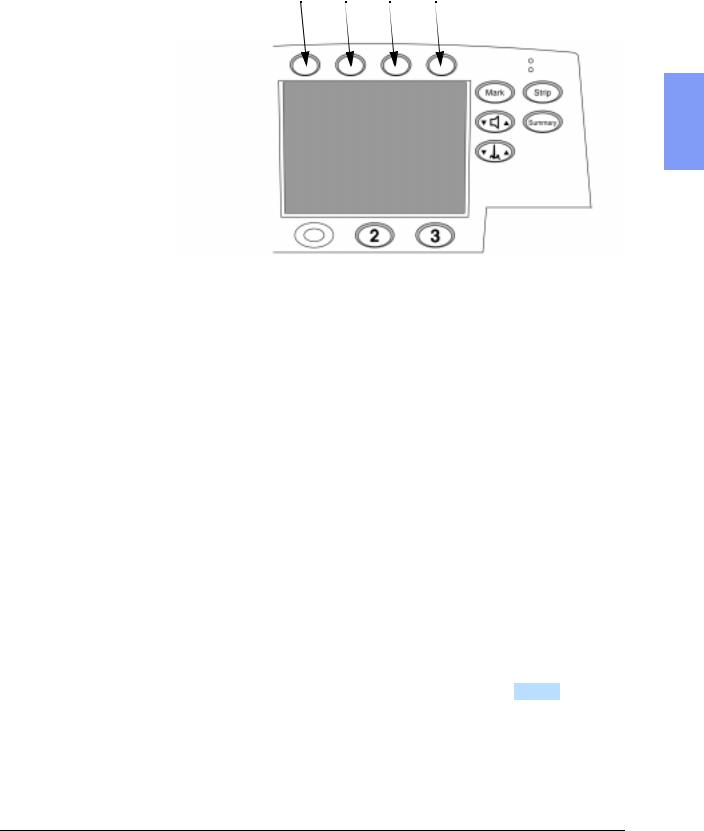
Press softkeys 4 and 5 at the same time, and hold them down while turning the power on. See Figure 2-1 for softkey numbering.
4.Select and manage Configuration choices.
lTo select a configuration, press the  and
and  softkeys to move up or down the list until the desired Settings item is highlighted. Then
press the ENTER softkey to access those settings.
lTo print out a strip with all the current configuration choices, select
Print All Settings and press ENTER .
lTo store the configuration settings on a data card, select Save Settings to Data Card and press ENTER . When prompted with Save Settings to Data Card? press SAVE .
lTo load configuration settings from a Data Card, select Load Settings from Data Card and press ENTER . When prompted with Load Settings from Data Card? press LOAD .
5.Exit Configuration Mode.
To exit Configuration Mode, turn the unit off. Remove the Data Card.
2-10 |
Performance Verification and Safety Tests |
Configuration and Diagnostic Modes
Figure 2-1 Softkey Numbers
Softkeys
4 |
5 |
6 |
7 |
2
Diagnostic Mode
These instructions describe how to enter Diagnostic Mode. Once in Diagnostic Mode, you can do the following:
lPrint the System Log. See "System Log" on page 2-20.
lRun the Extended Self Test. See "Extended Self Test" on page 2-22.
lRun other Diagnostic Tests. See "Diagnostic Tests" on page 2-19.
1.Power off.
Make sure the unit’s power is off.
2.Enter Diagnostic Mode.
Press softkeys 4 and 6 at the same time, and hold them down while turning the power on. See Figure 2-1 for softkey numbering.
3.Wait for the unit to initialize.
This may take several seconds. The unit is ready to proceed when the screen cursor responds to softkey inputs.
4.Select the desired test or function.
To select a test, press the  and
and  softkeys to move up or down the list until the desired test is highlighted. Then press the ENTER softkey to start that test.
5.Exit Diagnostic Mode.
To exit Diagnostic Mode, turn the unit off.
M4735A Service Manual |
2-11 |

The Software Support Tool
The Software Support Tool
The Software Support Tool (M4735-87890) allows field service personnel to perform 2 tasks: 1) to enable the SpO2 option, and 2) to program in the serial number. These tasks need to be performed under the following circumstances:
lThe Control PCA has been replaced.
The Control PCA contains all the operating software, configured for the installed hardware. It also contains the unit’s serial number, which was programmed in during manufacturing.
The new Control PCA must be programmed to recognize the hardware installed in this unit, and to contain that unit’s serial number.
lThe unit has received an upgrade adding the SpO2 capability.
The added hardware will not be automatically recognized. The Control PCA must be programmed to recognize the new hardware installed.
Using the Support Tool
1.Prepare the unit.
a.Have unit power off, and have either a fresh battery installed or the AC power cord plugged in.
b.Insert the Support Tool data card into the unit.
c.Turn unit power on.
2.Follow the screen prompts.
a.Select whether SpO2 hardware is installed or not as appropriate.
b.Program in the unit’s serial number.
lIf this is an SpO2 upgrade, the serial number should already be present. In this case, verify it against the factory-applied label on the bottom of the case.
lIf this is a Control PCA replacement, program in the serial number found on the factory-applied label on the bottom of the case using the softkeys as instructed on the screen. Be sure to program it in accurately, as the serial number is used for all repair history tracking.
c.Check all the displayed information carefully before proceeding.
lIf the displayed information is correct, follow the screen prompts to save the configuration.
2-12 |
Performance Verification and Safety Tests |

The Software Support Tool
lIf any of the information is incorrect, follow the prompts to NOT save the configuration, then start over by powering the unit off, then back on.
3.Turn off the power and remove the Data Card.
4.Check the customer configuration.
a.Turn the unit back on and enter Configuration Mode (see "Configuration Mode" on page 2-10).
b.Print the configuration and check it against the printout from before
the servicing began. Reset the configuration (or load it from a Data |
2 |
Card) as needed. |
|
5.Verify performance.
Perform Performance Verification Testing as described in "Performance Verification and Safety Tests" starting on page 2-1.
M4735A Service Manual |
2-13 |

Performance Verification
Performance Verification
This section gives instructions for running Performance Verification tests on the M4735A. The tests are sequenced to check more basic functions first, and then build on that to check more complex functions. We recommend you perform these tests in this sequence. If desired, you can make copies of the Test Results Matrix (page 2-4) and use it to record results.
The Performance Verification tests include:
Section |
Page |
Visual Inspection |
2-15 |
Functional Checks |
2-16 |
Diagnostic Tests |
2-19 |
Safety Tests |
2-39 |
Battery Capacity Test |
2-40 |
2-14 |
Performance Verification and Safety Tests |

Performance Verification
Visual Inspection
1. Inspect the unit.
Inspect the entire unit, especially paddles, power cord, printer, battery, cables, and sensors for signs of the following.
lWear or damage to paddles, cables, and adapters.
lWear or damage to patient cables and associated strain reliefs.
lMechanical damage to case, membrane switches, speaker cover, ambient light sensor cover, display window.
l Loose or missing hardware. |
2 |
lEvidence of liquid spill. Check inside the printer bucket and clean out any accumulation using gloves and an approved cleaner.
lResidue on the thermal printhead.
lPrinter roller wear.
lWear or damage to power cord and associated strain relief.
lCorrosion on connector pins, printer parts, or battery contacts.
Pass: Only normal wear, no damage serious enough to inhibit performance. No corrosion visible.
2.Check the consumables.
Check the ECG electrodes and defibrillator pads for freshness (data code or expiration date) and condition.
Pass: Electrodes and pads are within their expiration date and
appear usable. Packaging is unopened and shows no tears or punctures. No corrosion visible on connector sockets, electrodes, or pads.
M4735A Service Manual |
2-15 |

Performance Verification
Functional Checks
The following functional checks exercise the basic functions of the defibrillator/monitor. They are intended as a broad check of the unit’s performance, and are designed to complement (not replace) the Diagnostic Tests described later.
If all elements of a test pass, record that test as a PASS and return to the main
diagnostic menu by pressing MAIN . If there is any failure, begin troubleshooting and repairing as needed. See "Troubleshooting" on page 3-1.
The Functional Checks include:
Check |
Page |
ECG Functional Checks |
2-16 |
Shock Advisory Functional Check |
2-17 |
Synchronized Cardioversion Functional |
2-18 |
Check |
|
Sp02 Functional Check |
2-18 |
ECG Functional Checks
This section describes how to check the operation of the ECG functions. Each of the ECG checks assumes the unit and the simulator are still set up as they were at the end of the previous ECG check.
To check ECG display and Heart Rate (HR) functions:
1.Set up the simulator.
a.Connect the ECG simulator to both the Pads input and the 3- or 5-lead ECG cable.
b.Set the simulator for normal sinus rhythm (NSR), 1mV amplitude, at some nominal rate (e.g., 60 bpm).
2.Set up the M4735A.
Set the M4735A to Manual operating mode (not Diagnostic Mode).
3.Check the displayed ECG.
Using the LEAD SELECT softkey, verify that the display shows a normal ECG with a clean baseline for both Pads and Lead II.
4.Check the Heart Rate (HR).
Verify that the Heart Rate (HR) displayed is correct.
5.Check Leads Off.
a.Disconnect the ECG simulator from the pads cable and verify that the display shows a dashed line in place of the waveform and that the unit both alarms and gives the Pads Off message
b.If using a 5-lead ECG cable, set the unit to monitor from the V lead.
2-16 |
Performance Verification and Safety Tests |
Loading...