

Page 1

Conventional
Models
2007 EPA Compliant Vehicles
Page 2

Q
uick Table of Contents
Introduction . . . . . . . . . . . . . . . . . . 1
Cab And Frame Access . . . . . . . . . . . .5
Getting To Your Engine. . . . . . . . . . . . . . . 11
Controls And Displays. . . . . . . . . . . . . . . . . . . 13
Seat And Restraint Systems . . . . . . . . . . . . . . . . . 73
Driver’s Checklists . . . . . . . . . . . . . . . . . . . . . . . . . . . 84
Starting And Operating The Vehicle. . . . . . . . . . . . . . . . . . 88
Consumer Information . . . . . . . . . . . . . . . . . . . . . . . . . . . . . . . . . . . . . 216
Subject Index . . . . . . . . . . . . . . . . . . . . . . . . . . . . . . . . . . . . . . . . . . . . . . . 219
Maintenance and Service . . . . . . . . . . . . . . . . . . . . . . . . . . 129
Vehicle Identification . . . . . . . . . . . . . . . . . . . . . . . . . . . . . . . . . . . 215
California Proposition 65 Warning
• Diesel engine exhaust and some of its constituents are known to the State of
California to cause cancer, birth defects, and other reproductive harm.
• Other chemicals in this vehicle are also known to the State of California to
cause cancer, birth defects or other reproductive harm.
• Battery posts, terminals, and related accessories contain lead and lead compounds, chemicals known to the State of Calif ornia to cause cancer and reproductive harm. Wash hands after handling.
Page 3

PART 1: INTRODUCTION HOW TO FIND WHAT YOU WANT
PART 1: INTRODUCTION
This manual contains useful information for the safe and
efficient operation of your P eterbilt vehicle . It also provides
information on maintaining your vehicle in the best condition, with an outline for performing safety checks and
basic preventive maintenance inspections.
We have tried to present the information you’ll need to
learn about your vehicle’s functions, controls, and operation - and to present it as clearly as possible. We hope
you’ll find this manual easy to use.
Please remember -- this manual is not a training manual.
It can’t tell you everything you need to know about driving
your Peterbilt vehicle. For that you need a good training
program or truck driving school. If you have not been
trained, get the proper training before you drive. Only
qualified drivers should drive this vehicle.
There will be times when you need to take this manual out
of your Peterbilt. When you do, please be sure to return it
to the cab when you are finished using it. That way it will
be there when you need it th e next time or when you pass
the vehicle on to the next user.
How To Find What You Want
There are several tools built into this manual to help you
find what you need quickly and easily.
First is the Quick Table of Contents. Located at the front
of the manual, this lists the main subjects covered and
gives page numbers where you can find these subjects.
Use the Quick Table of Contents to find information on a
large subject like “Maintenance.”
Cross-referenced citations also help you get the information you need. If some other part of the manual contains
further information o n the subject you are reading about,
we’ll indicate that in a cross-reference like this: (See
“PART 6: DRIVER’S CHECKLIST”). You won’t have to go
searching for more information.
Finally you’ll find a helpful Subject Index. It’s in the back
of the manual and alphabetically lists the subjects covered. So if you want information on brakes, for example,
just look under Brake in the Subject Index. You’ll find all
the pages listed where brakes or braking are discussed.
(08/06) Y53-6004 – 1 –
Page 4
A SPECIAL WORD ABOUT REPAIRS PART 1: INTRODUCTION
A Special Word About Repairs
WARNING ! Attempting repair work without sufficient training, service manuals, and the proper
tools can be dangerous. You could be injured or
you could make your truck unsafe. Do only
those tasks you are fully qualified to do.
Your Peterbilt dealer’s service center is the best place to
have your vehicle repaired. You can find Peterbilt dealers all
over the country with the equipment and trained personnel
to get you back on the road quickly - and k eep you there.
Your vehicle is a complex machine. Anyone attempting
repairs on it needs good mechanical training and the
proper tools. If you are sure you have these requirements,
then you can probably perf orm some repairs yourself . However, all warranty repairs must be performed by an authorized Peterbilt service facility. If you aren’t an experienced
mechanic, or don’t have the right equipment, please leave
all repairs to an authorized service facility. They are the
ones equipped to do the job safely and correctly.
Maintenance Manuals. If you do decide to do any complex repair work, you’ll need the Peterbilt Maintenance
manuals. Order them from your authorized dealer. Please
provide your Chassis Serial Number when you order, to
be sure you get the correct manuals for your vehicle.
Allow about four weeks f or deliv ery. There will be a charge
for these manuals.
Final Chassis Bill of Material. A complete, nonillustrated
computer printout listing of the parts used to custom-build
your Peterbilt vehicle is available through the Peterbilt
dealer from whom your purchased your vehicle.
WARNING! Modifying y our ve hicle can make it
unsafe. Some modifications can affect your
truck’s electrical system, stability, or other
important functions. Before modifying your
vehicle, check with your dealer to make sure it
can be done safely.
Additional Sources of Information
Operator’s manuals are also supplied by the manufacturers of components such as the engine, seats, transmission, and radio in your Peterbilt. If you are missing any of
these manuals, ask your Peterbilt dealer to supply them.
Your new Peterbilt’s glove box also contains a copy of the
Truck Driver’s Handbook, published by the American
Trucking Association. Refer to it for important information
on driving your vehicle . Another pl ace to learn more about
– 2 – Y53-6004 (08/06)
Page 5
PART 1: INTRODUCTION WARNINGS
trucking is a local truck driving school. Contact one near
you to find out what kinds of instruction it offers.
Federal and state agencies also have inf ormation you can ask
for . The Interstate Commerce Commission can give you information about regulations governing transportation ac ross
state lines. And various agencies in state governments are
sources for regulations that differ from state to state.
Warnings
We’ve put a number of warning messages in this manual.
They are there f or y ou r prot ection and information. Please
read them and follow them. They can help you to avoid
injury to yourself and your passengers as well as to prevent costly damage to your vehicle. We’ve used cer tain
symbols and “signal words” to indicate what kind of message is going to follow. When you see these symbols &
words, you know that you need to pay special attention.
Please don’t ignore any of these signals.
WARNING!
When you see this symbol & word, the message that follows is especially vital. This signals something that can
cause serious injury or death. This message will tell you
what the hazard is, what can ha ppe n if you don’t heed the
warning, and how to avoid it. For example:
WARNING! Attempting repair work without
sufficient training, service ma nuals, and the
proper tools can be dangerous. You could be
injured or you could make your vehicle
unsafe. Do only those tasks you are fully qualified to do.
CAUTION:
This symbol & word signals something that could damage
your vehicle. You might receive an injury, too. For example:
CAUTION: Continuing to operate a vehicle
with insufficient oil pressure will cause serious engine damage.
NOTE:
Gives you infor mation we feel you’d like to have. It could
have to do with care of your vehicle or with driving more
efficiently:
(08/06) Y53-6004 – 3 –
Page 6
VEHICLE SAFETY PART 1: INTRODUCTION
NOTE: A cold compressor can cause refrigerant
to liquefy and warp the valve plates or cause a
hydraulic lock. Warm the en gine before starting
the air conditioner.
Please take the time to read these messages when you
see them. And remember:
WARNING! Something that could injure y ou seriousl y.
CAUTION: Something that could cause injury to you
or your vehicle.
NOTE: Useful information.
Vehicle Safety
Make sure your Peterbilt is in top working condition before
heading out on the road—it is the responsible driver's duty
to do so. Inspect the vehicle according to “
DRIVER’S CHECKLIST.”
WARNING!
reflexes, perceptions, and judgment can be
affected by even a small amount of alcohol. You
could have a serious—or even fatal accident—if
you drive after drinking. Please do not drink and
drive or ride with a driver who has been drinking.
Do not drink and drive. Your
PA R T 6:
WARNING! The use of alcohol, drugs, and certain medications will seriously impair perception, reactions, and driving ability. These
circumstances can substantially increase the
risk of an accident and personal injury.
Please remember, this manual is not a training manual. It
cannot tell you everything you need to know about driving
your Peterbilt vehicle. For that you need a good training
program or truck driving school. If you have not been
trained, get the proper training before you drive. Only
qualified drivers should drive this vehicle.
Every new Peterbilt vehicle is designed to conform to all
Federal Motor Vehicle Safety Standards applicable at the
time of manufacture. However, even with these safety features, continued safe and reliable operation depends
greatly upon regular vehicle maintenance. The vehicle
must be operated within the range of its mechanical capabilities and the limits of its load ratings. (See the Tire and
Rim Weight Ratings label on the driver's door edge.)
– 4 – Y53-6004 (08/06)
Page 7

PART 2: CAB AND FRAME ACCESS
PART 2: CAB AND FRAME ACCESS
Be careful whenever you get into or out of your vehicle’s
cab. Always maintain at least three points of contact with
your hands on the grab handles and your feet on the
steps.
WARNING! Jumping out of the cab or getting
into the cab without proper caution is dangerous. You could slip and fall, possibly suffering
a serious injury. Keep steps clean. Clean any
fuel, oil, or grease off of the steps before
entering the cab. Use the steps and grab handles provided, and always keep at least three
points of contact between your hands and
feet and the truck. Look where you are go ing.
(08/06) Y53-6004 – 5 –
Page 8
DOOR LOCK AND KEYS PART 2: CAB AND FRAME ACCESS
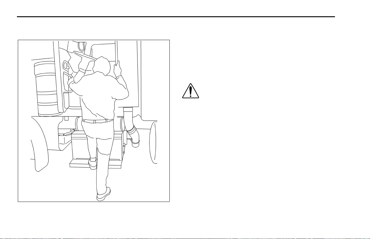
The picture below shows the best way to enter and exit a
Conventional Cab.
02958B
Door Lock and Keys
Doors can be locked from th e insid e b y usin g the lock button. Close the door then push the button down to lock.
Doors automatically unlock when you open them from
inside, and can be locked from the outside with the key
only.
WARNI NG! To lessen the chance and/or s everity of personal injury in case of an accident,
always lock the doors while driving. Along
with using the lap/shoulder belts properly,
locking the doors helps prevent occupants
from being thrown from the vehicle.
To lock or unlock the doors from outside the cab , insert the
key in the lock.Turn the key toward the rear to lock; forward to unlock.
Keys and Loc ks
The same key fits your ignition, doors, and sleeper luggage compartment.
Frame-mounted tool box locks and locking fuel tank caps
each have individual keys.
– 6 – (08/06) (08/06)
Page 9

PART 2: CAB AND FRAME ACCESS DOOR LOCK AND KEYS
Remote Keyless Entry (optional)
This vehicle may be equipped with a Remote Keyless
Entry (RKE) system that adds security and convenience
to your vehicle. The system will lock or unlock the driver’s
door and passenger’s door with the key fob and alert you
with parking lights when the selected door’s are locked or
unlocked. The system includes two key fobs that provide
secure rolling code technology that prevents someone
from recording the entry signal.
Operation
To Unlock The Driver’s Door
Press the UNLOCK button once. The driver's door will
unlock and the parking lights will come on for 40 seconds.
To Unlock The Passenger’s Door
Press the UNLOCK button once and press again
within 5 seconds. The passenger door will unlock.
To Lock Both Doors
Press the LOCK button. The doors will lock and the
parking lights will come on for 2 seconds. If the doors
are open they will not lock. The range of the RKE sys-
tem should be approximately 30 ft. This will be
reduced if it is operated close to other RF sources
such as TV/radio transmitters and cell tow ers.
Batteries
The key fob uses one CR2032, 3V battery. Batteries
should last approximately three years, depending on use.
Consistently reduced range is an indicator that the battery
needs replacement. Batteries are available at most discount, hardware and drug stores.
To Replace The Battery
1. Remove rear cover from key fob.
2. Remove the battery.
3. Install new battery.
4. Reinstall cover.
5. Synchronize the key fob.
Synchronization
The key fob may need to be synchronized to the tr uck
when the battery is replaced or when the key fob has not
been used for an extended period time.
(08/06) Y53-6004 – 7 –
Page 10

DOOR LOCK AND KEYS PART 2: CAB AND FRAME ACCESS
To Synchronize A Key Fob
1. Hold the key fob near the receiver.
NOTE: The receiver is located behind the Speedometer/
Tachometer cluster assembly.
2. Press and hold both the Lock and Unlock buttons at
the same time for approximately 7 seconds.
3. When the key fob is resynchronized, the doors will
lock then immediately unlock.
4. If the fob fails to synchronize, it could be programmed to a different truck or could have failed.
Contact your dealer to re-program your key fob.
– 8 – (08/06) (08/06)
Page 11
PART 2: CAB AND FRAME ACCESS CLIMBING ONTO THE DECK PLATE
Climbing Onto the Deck Plate
When you are climbing onto and off the deck plate, maintain at least three points of contact with your hands on the
grab handles and your feet on the steps.
WARNING!
• You can be hurt if you aren’t careful climbing onto and off the deck plate. You can slip
and fall, especially if the surfaces are wet or
icy, or if you step in oil, fuel, or grease. Keep
steps clean. Always maintain at least three
points of contact between your hands and
feet and the steps and deck plate.
• Do not climb onto and off the dec kplate–use
steps and grabhandle provided. If there is no
deck plate, or if proper steps and grab handles aren’t provided, don’t c limb onto the area
behind the cab. Peterbilt did not intend for the
area to be a step if handrails or proper steps
are not provided.
WARNING! Do not step on vehicle components without antiskid surfaces or use components not designed for entry-and-exit use.
You could fall and injure yourself if you step
on a slippery surface. For example:
• You could fall and injure yourself if you step
onto a fuel tank surface. A fuel tank is not a
step. The tank surface can get very slippery,
and you might not be able to prevent a fall.
Don’t step onto the surface of a fuel tank. Use
only the steps and handholds provided, not
chain hooks, quarter fenders, etc.
• Always reinstall steps before entering the
cab or accessing the deck plate. Without
steps, you could sli p and fall, resulting in possible injury to yourself.
NOTE: Any alteration (adding bulkheads, headache racks, tool boxes, etc.) behind the cab or
sleeper that affects the utilization of grab handles ,
deck plates, or frame access steps installed by
Peterbilt must comply with FMCSR 399.
The pictures on the next page show you the right way to
get on and off the area behind your cab.
(08/06) Y53-6004 – 9 –
Page 12
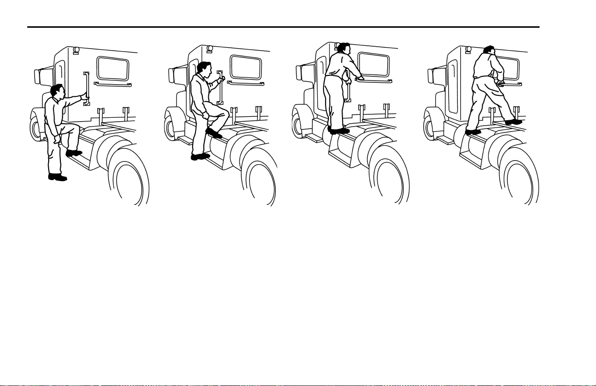
CLIMBING ONTO THE DECK PLATE PART 2: CAB AND FRAME ACCESS
Hold handles as you
step up.
– 10 – (08/06) (08/06)
Maintain three points
of contact.
Maintain three points of
contact as you reach the
deck area.
Maintain three points of
contact as you step to
deckplate.
Page 13
PART 3: GETTING TO YOUR ENGINE HOOD HOLD DOWNS
PART 3: GETTING TO YOUR ENGINE
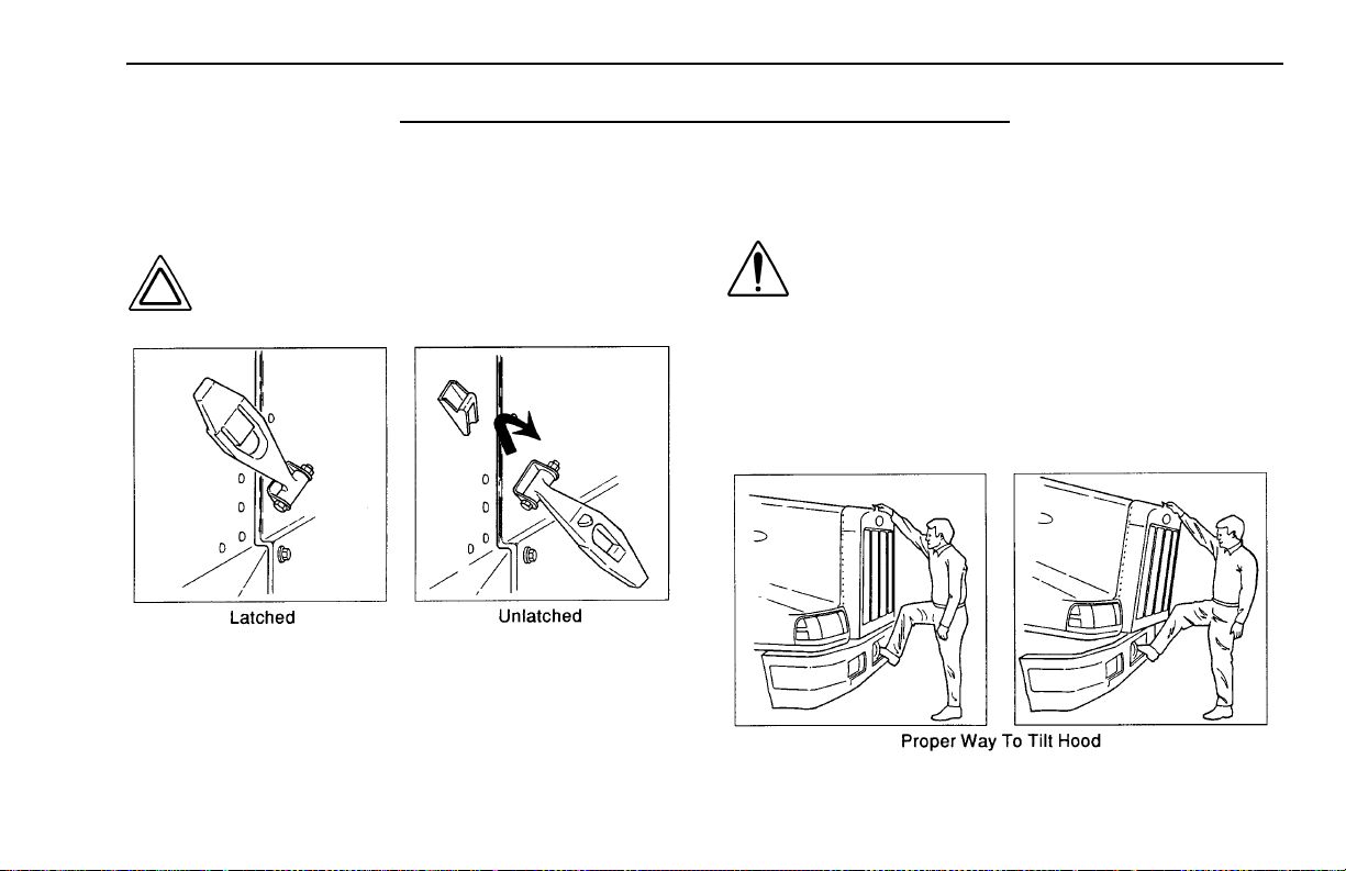
Hood Hold Downs
Hood hold downs keep a hood fr om opening une xpectedly
CAUTION: A hood not latched securely could
open during operation and cause vehicle
damage. Be sure to latch the hood securely.
02961
Hood Tilt
To open your hood, unlock the hood hold downs by
unlatching them. Put one hand on the top of the hood
front, one foot on the bumper, and one f oot o n the g round.
Tilt the hood forwar d
WARNING! Before opening or closing a hood,
ensure no people or objects are in the way. A
hood could hurt someone in the way of its
descent. If the hood falls, anyone under it
could be injured. Always ensure the hood
hold-open latch is engaged to keep the hood
open any time any one gets under the hood f or
.
any reason.
02962
(08/06) Y53-6004 – 11 –
Page 14
HOOD TILT PART 3: GETTING TO YOUR ENGINE
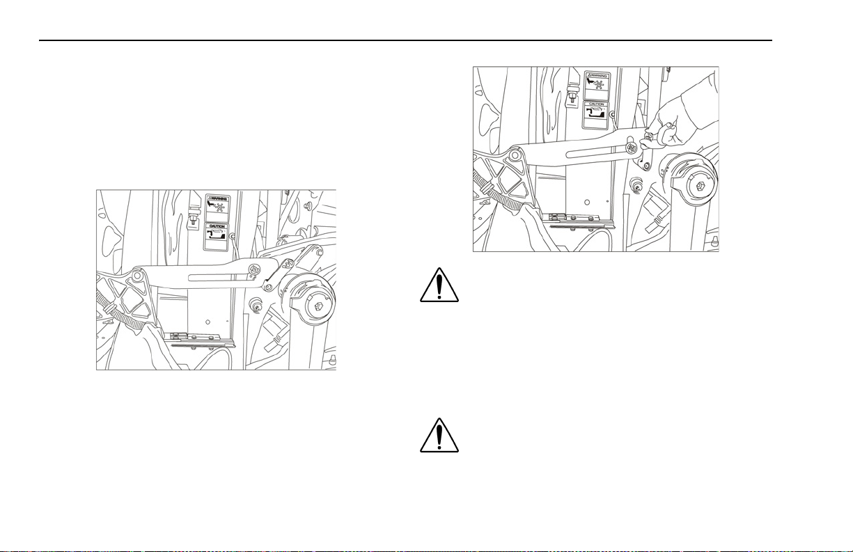
Hood Hold-Open Device
The hood is equipped with a hood hold-open device. In
order for the hood hold-open device to become engaged,
the vehicle hood must be fully open. Once the vehicle
hood is fully open, the hold-open latches will automatically
engage and will need to be disengaged by the operator.
WARNING!
• Ensure the hood is fully opened. Failure to
fully open the hood will prevent engagement
of the hold-open device causing possible serious bodily injury.
• Ensure the hold-open device is engaged
To disengage the latch f or hood closure, rotate the release
lever fully forward.
when underneath hood. A closing hood can
crush causing possible serious bodily injury.
WARNING! K eep people or objects clear when
opening or closing a hood. Failure to do so
can cause hood to strike or crush causing
possible serious bodily injury and/or property
damage.
– 12 – Y53-6004 (08/06)
Page 15

PART 4: CONTROLS AND DISPLAYS YOUR INSTRUMENT PANEL
PART 4: CONTROLS AND DISPLAYS
Your Instrument Panel
This part explains the location of the various features on
your vehicle and describes their function. For information
on using these features in driving, see the paragr aphs that
follow. Please remember that each Peterbilt is custommade. Your instrument panel may not look exactly like the
one in the pictures that follow. We have tried to describe
the most common features and controls a vailab le. You can
pick out the parts that apply to you and read them to be
fully informed on how your par ticular vehicle operates.
(08/06) Y53-6004 – 13 –
Page 16
YOUR INSTRUMENT PANEL PART 4: CONTROLS AND DISPLAYS
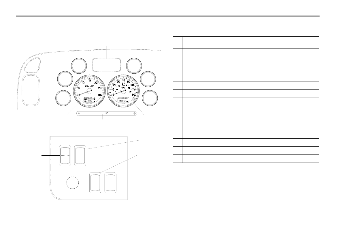
Typical Conventional Cab Instruments and
Controls
6
5
4
3
2
1
I
I
12
O
O
I
I
11
O
O
7
8
9
10
Panel A
13
14
15
Panel C
LEFT SIDE
1 Directional Signal and High Beam Indicators (standard) (Note: Custom warning lights
are added in this area.)
2Tachometer
3 Oil Pressure
4 Coolant Temperature
5 Voltmeter
6 Driver Information Display
7Fuel Level
8Primary Air Pressure
9 Secondary Air Pressu re
10 Speedometer
11 Igni ti on Key Switch
12 Headlamps
13 Clearance Lamps
14 Panel Light Dimmer
15 Hazard Flasher
– 14 – Y53-6004 (08/06)
Page 17
PART 4: CONTROLS AND DISPLAYS YOUR INSTRUMENT PANEL
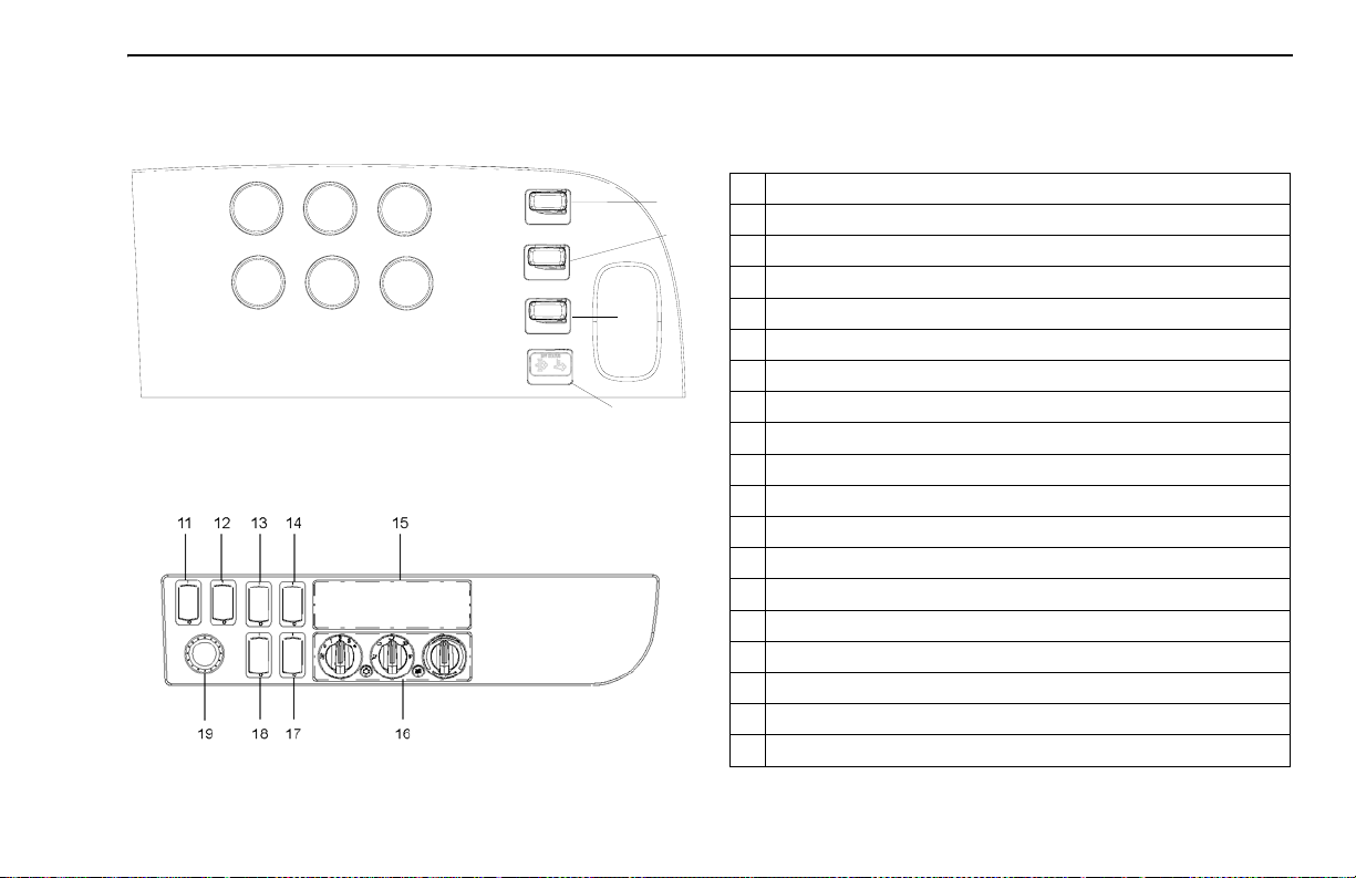
Conventional
RIGHT SIDE
1
4
2
5
3
6
7
8
9
10
Panel B
1 Oil Temperature
2 Transmission Oil Temperature
3 Front Driver Oil Temperature
4 Brake Application Pressure
5 Air Cleaner Restriction
6 Rear Driver Oil Temperature
7 Air Suspension Deflate
8 Fifth Wheel Lock
9 Interaxle Differential Lock
10 Exhaust Regeneration Display
11 Engine Fan
12 Fuel Tank Selector
13 Engine Brake On/Off
14 Engine Brake Selector
15 Radio
16 HVAC Control Panel
17 Cruise Control Select
18 Cruise Control On/Off
19 Menu Control Switch (MCS)
(08/06) Y53-6004 – 15 –
Page 18
INSTRUMENTS AND CONTROLS PART 4: CONTROLS AND DISPLAYS
Instruments And Controls
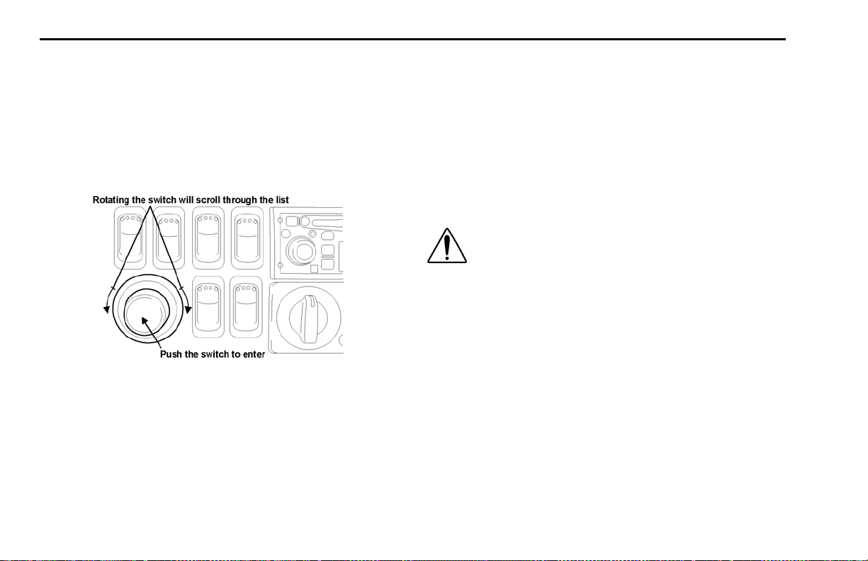
Menu Control Switch (MCS)
The MCS is used to navigate the Driver Information Display unit.
as shown in the illustration below.
The MCS has the following functions:
• Rotating the MSC
The Menu Control Switch is located on the D Panel
– Selecting display
• Pushing the MSC
– Confirming desired selection
Standard Warning Lights and Audible Alarm
The warning lights and audible alarm may indicate a system malfunction. Check the lights frequently, and respond
properly as soon as you see one go on. These lights could
save you from a serious accident.
WARNING! Do not ignore a warning light or
audbile alarm. These signals tell you something is wrong with your vehicle. It could be a
failure in an important system, such as the
brakes, which could lead to an accident. Have
the appropriate system checked immediately.
– Setting values
– 16 – Y53-6004 (08/06)
Page 19
PART 4: CONTROLS AND DISPLAYS INSTRUMENTS AND CONTROLS
active, the menu control switch (MCS) can be used to
scroll through the additional warnings.
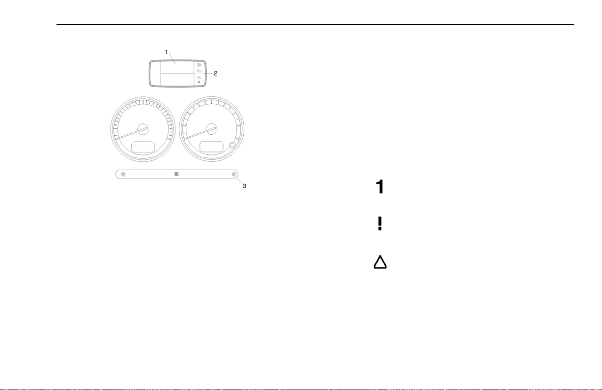
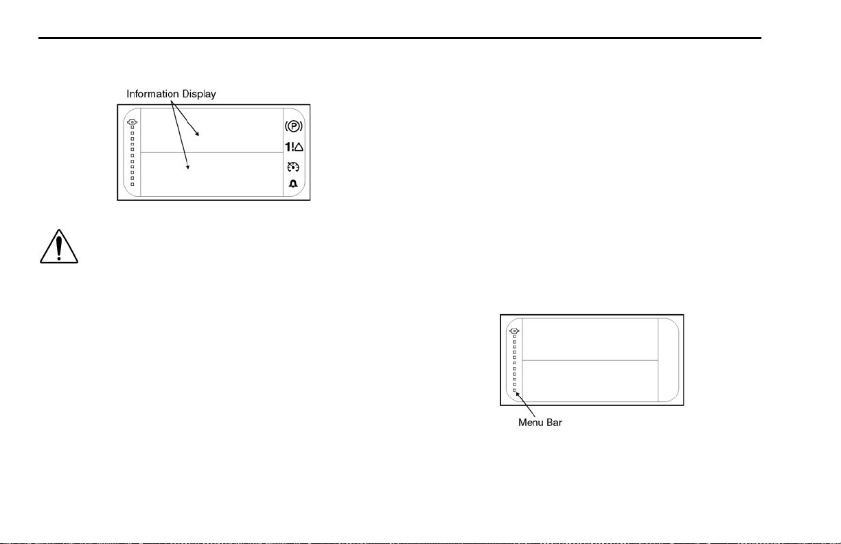
2. Status Indicator:
Additional lights and indicator symbols are displayed in
the Status Indicator. They are limited to:
a. Park Brake
b. Transmission Gear (Automatic transmissions
only)
c. Warnings:
Number of active warnings.
1. Driver Information Display 2. Status Indicator
3. Lower Light Bar
A red warning is active.
Warning lights and indicator symbols will be shown in both
areas 1 and 2. Area 3 is dedicated to the tur n and high
An amber warning is active.
beam indicator symbols.
1. Driver Information Display:
The display can show up to six warning lights. Warnings
do not have fixed positions and are displayed in order of
criticality. The most critical warning will be displayed on
d. Cruise Control - active
e. Clock alarm bell
Refer to “War ning Light / Indicator Symbols” on page 19
for inform ation on each symbol.
the top row and to the left. If more than six warnings are
(08/06) Y53-6004 – 17 –
Page 20
INSTRUMENTS AND CONTROLS PART 4: CONTROLS AND DISPLAYS
Instrument System Self Test:
When the ignition switch is turned on the instrumentation
system will undergo a Self Test. This test will verify the
operation of the gauges and warnings.
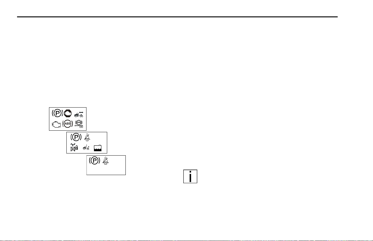
During the Instrumentation System Self Test, three
screens will sequentially display warning icons (approximately 3 seconds each screen) on the Information Display. These are:
First
Second
Third
Refer to “War ning Light / Indicator Symbols” on page 19
for information on each symbol.
Completing this sequence will indicate a successful Self
Test. Have your instrumentation system checked by a
qualitfied service technician if does not successfully complete.
Audible Alarm:
The audible alarm will sound during the In strumenta tion
System Self Test. The audible alarm will also sound in
conjunction with most warning lights. These events
include but are not limited to headlight on, fifth wheel, stop
engine, primary/secondar y air, and driver door open
warnings.
Optional Lights:
Additional lights may be operatio nal depend ing on individual vehicle specifications. These will be included in the
Instrument System Self Test.
NOTE: Some optional lights may illuminate even
though your vehicle is not equipped with that particular feature.
– 18 – Y53-6004 (08/06)
Page 21
PART 4: CONTROLS AND DISPLAYS INSTRUMENTS AND CONTROLS
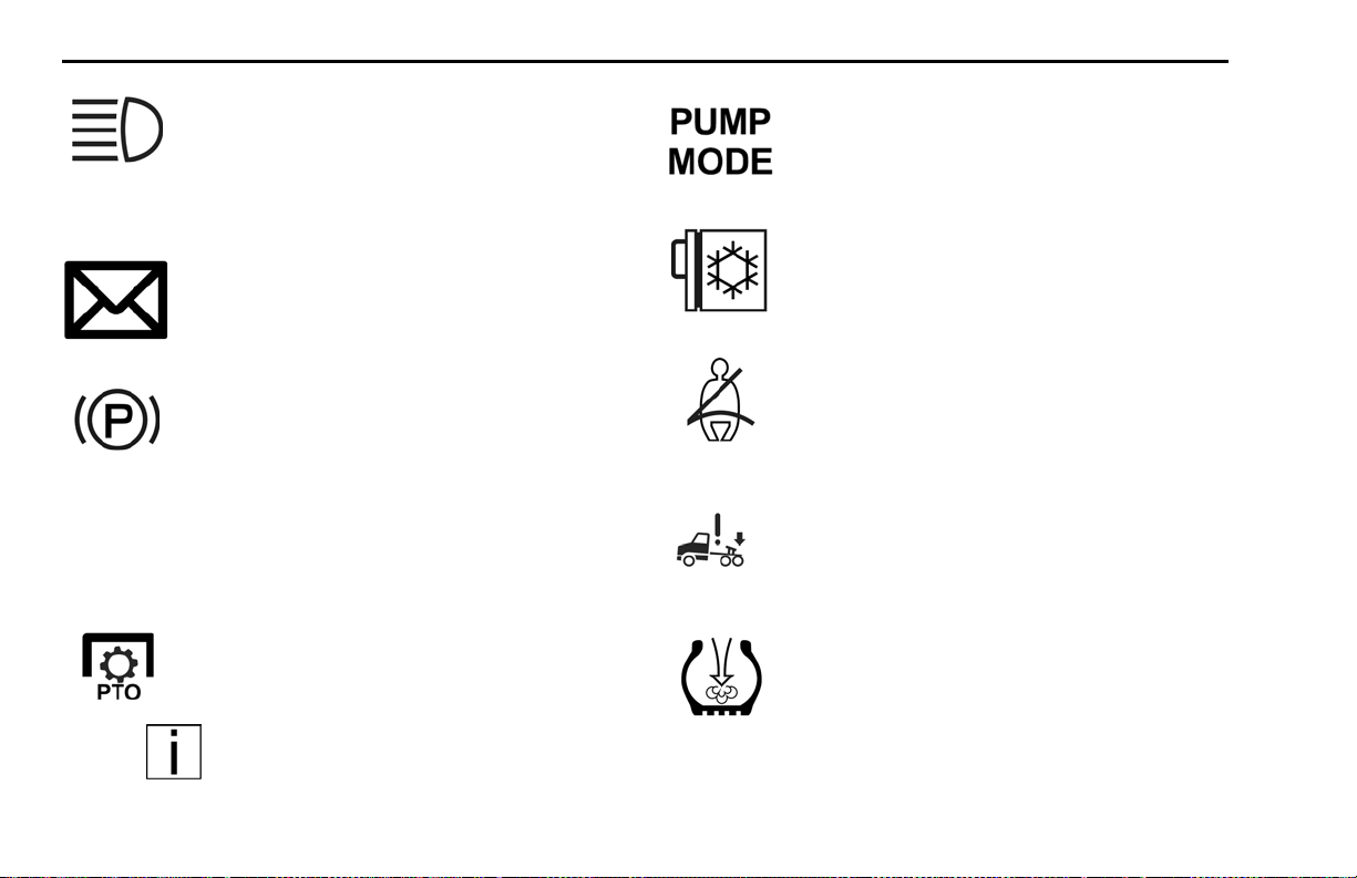
Warning Light / Indicator Symbols
The following is a list of W arning Light / Indicator Symbols.
Reading left to right, the table header identifies
• the Symbol Name
• the appearance of the Symbol
• the Symbol Color when it is illuminated
• whether the symbol is standard (Std) or op tional (Op t)
• the Page Number reference for additional information
Symbols are listed by major component sections.
Example: Engine, and then in alphabetical order.
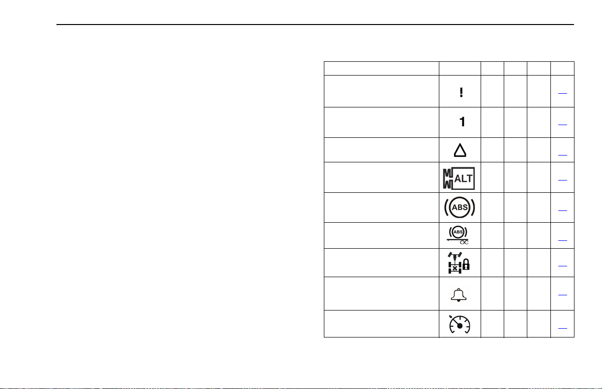
Warning Light / Indicator Symbols
Symbol Name Symbol Color Std Opt Page
1. Active Warnings, Exclamation
Point
2. Active Warnings, Number
3. Active Warnings, Triangle
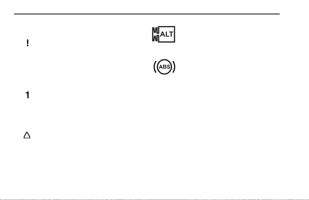
4. Alternator
5. Anti-Lock Brake System
(ABS)
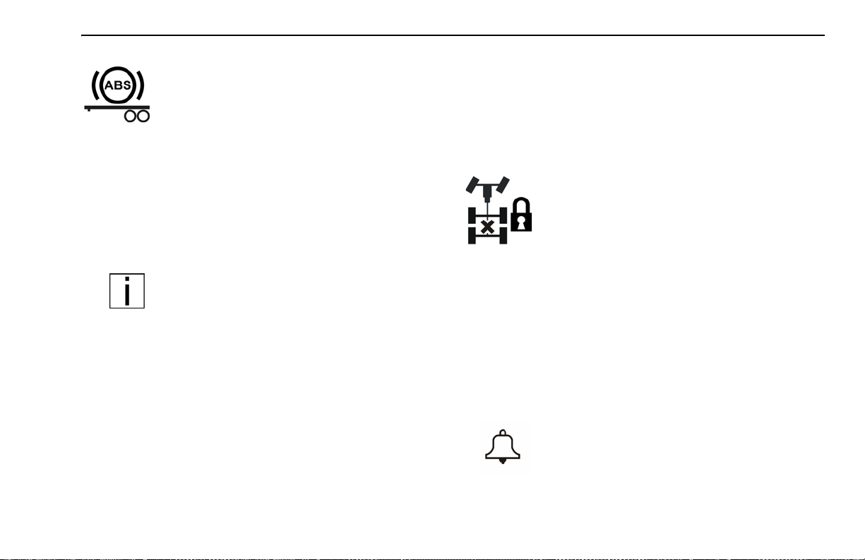
6. Anti-Lock Brake System
(ABS), Trailer
7. Axle, Inter-Axle Differential
Locked (Tandem Axles)
8. Clock, Alarm Bell
9. Cruise Control, Active
Red
Yellow
Yellow
Red
Yellow
Yellow
Yellow
Yellow
Yellow
22
22
22
22
22
23
23
23
24
(08/06) Y53-6004 – 19 –
Page 22
INSTRUMENTS AND CONTROLS PART 4: CONTROLS AND DISPLAYS
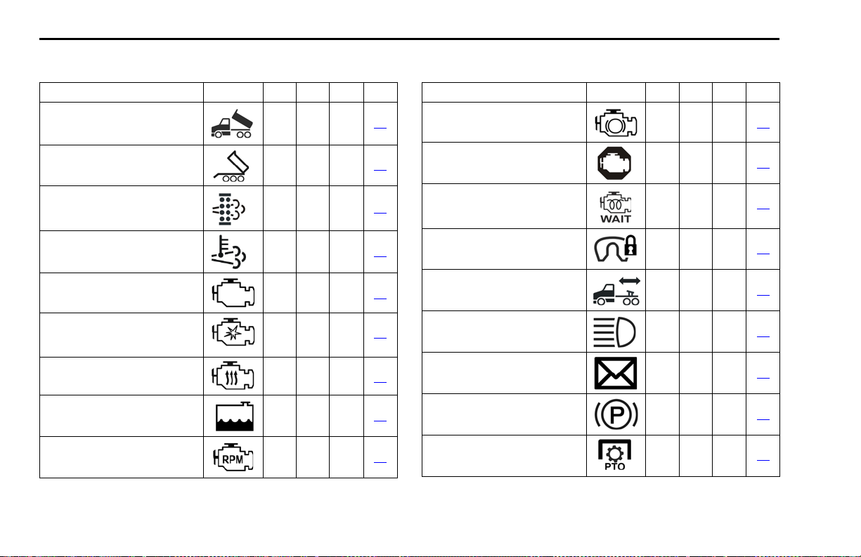
Warning Light / Indicator Symbols
Symbol Name Symbol Color Std Opt Page
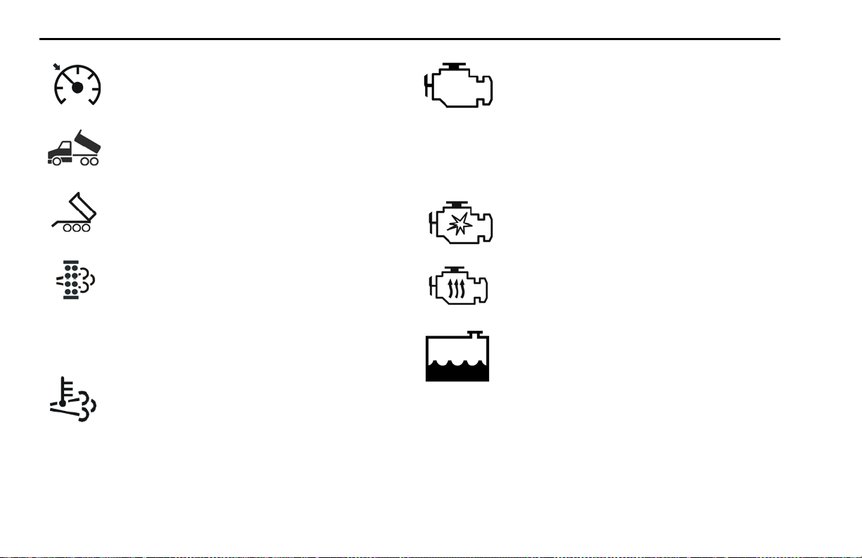
10. Dump Truck, Body Up
11. Dump Truck, Trailer Body Up
12. Emissions, Diesel Particulate Filter (DPF)
13. Emissions, High Exhaust
System Temperture (HEST)
14. Engine, Check Engine
15. Engine, Ether Start
16. Engine, Heater
17. Engine, Low Coolant Level
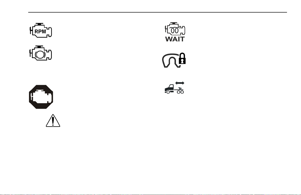
18. Engine, Overspeed
Yellow
Yellow
Yellow
Yellow
Yellow
Green
Yellow
Yellow
Red
24
24
24
24
24
24
24
24
25
Warning Light / Indicator Symbols
Symbol Name Symbol Color Std Opt Page
19. Engine, Retarder (Brake)
20. Engine, Stop Engine
21. Engine, Wait To Start
22. Fifth Wheel, King Pin Lock
23. Fifth Wheel, Slide Unlocked
24. Lights, High Beam
25. Message Waiting
26. Park Brake
27. Power Take-off (PTO)
Green
Red
Yellow
Red
Red
Blue
Green
Red
Green
25
25
25
25
25
26
26
26
26
– 20 – Y53-6004 (08/06)
Page 23
PART 4: CONTROLS AND DISPLAYS INSTRUMENTS AND CONTROLS
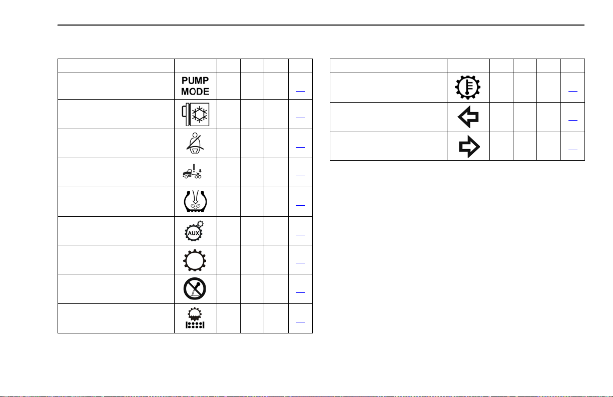
Warning Light / Indicator Symbols
Symbol Name Symbol Color Std Opt Page
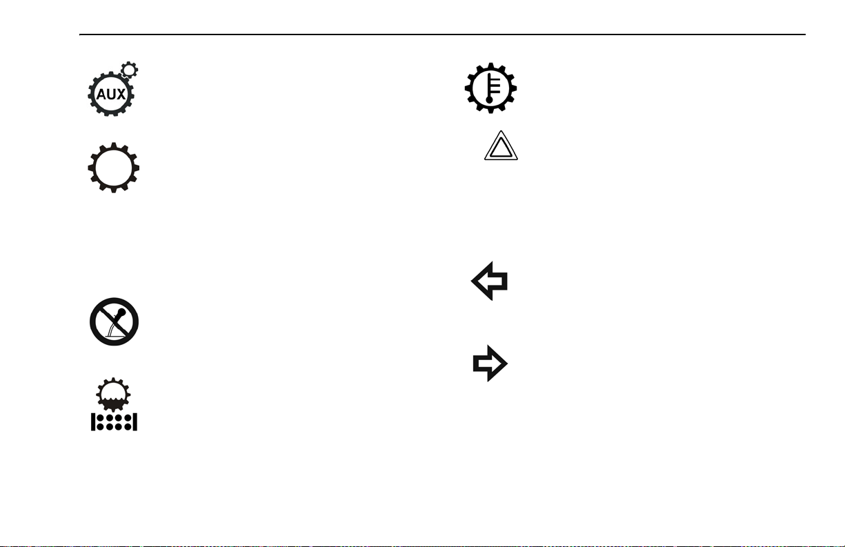
28. Power Take-off (PTO), Pump
Mode
29. Refrigerator
30. Seat Belt, Fasten
31. Suspension Dump
32. Tire Inflation
33. Transmission, Auxiliary
34. Transmission, Check
35. Transmission, Do Not Shift
36. Transmission, Oil Filter
Green
Green
Red
Yellow
Yellow
Yellow
Red
Red
Yellow
26
26
26
26
26
27
27
27
27
Warning Light / Indicator Symbols
Symbol Name Symbol Color Std Opt Page
37. Transmission, Oil Temperature High
38. Turn Signal, Left
39. Turn Signal, Right
Yellow
Green
Green
27
27
27
(08/06) Y53-6004 – 21 –
Page 24
INSTRUMENTS AND CONTROLS PART 4: CONTROLS AND DISPLAYS
Warning Light/Indicator Symbol Descriptions
1. Active Warnings, Exclamation Point
Illuminates when a red warning is active. Use
the MCS knob to view the warnings that are
active. Refer to the preceedin g Figure ,
“Warning Light / Indicator Symbols,” on
page 19 for warning color classification.
2.Active Warnings, Number
Illuminates the total number of red and y ellow
active warnings.
active warnings if the display shows a > symbol.
Use the MCS to view the
3.Active Warnings, Triangle
Illuminates when an yellow warning is active.
Use the MCS knob to view the warnings that
are active. Refer to the preceeding Figure ,
“Warning Light / Indicator Symbols,” on
page 19 for warning color classification.
4.Alternator
Illuminates if the alternator is not charging.
(For alternators with warning lamp output
signal.)
5. Anti- L ock Brake System (A BS)
Illuminates during the Instrumentation System Self Test. Have the ABS system checked
by a Peterbilt dealer if the ABS War ning
Lamp stays on for more than 3 seconds.
Illuminates during normal operating conditions to indicate a problem with the ABS System. See “ABS Warning Lamps” on page 104
for more information.
Illuminates when a problem exists with the
optional Wheel Spin Control feature. See
“Advanced ABS with Stability Control” on
page 106 more infor mation.
– 22 – Y53-6004 (08/06)
Page 25
PART 4: CONTROLS AND DISPLAYS INSTRUMENTS AND CONTROLS
6. Anti-Lock Brake System (ABS), Trailer
Illuminates during the Instrumentation System Self Test and the tractor/truck is connected with a ABS equipped trailer.
Illuminates during normal operating conditions to indicate a problem with the Trailer
ABS System. This should be checked by a
Peterbilt dealer as soon as possible. See
“ABS Warning Lamps” on page 104 for more
information.
NOTE:
• Tractors/Trucks and trailers built after 3/1/01
must be able to turn on an In-Cab Trailer ABS
Warning Lamp (per U.S. FMVSS121). The
industry chose Power Line Communication
(PLC) as the standard method to turn it on.
See “Trailer ABS Warning Lamp” on page 104
for more information
• On trailers built prior to 3/1/01 verify trailer
ABS system status via the required external
warning lamp mounted on the trailer. The
indicator lamp on the trailer should be yellow
and identified with the letters "ABS".
7. Axle, Inter-Axle Differential Locked
(Tandem Axles)
Illuminates when the inter-axle differential
switch is ON thus locking the inter-axle differential. This powers the forward rear and the
rear rear differentials equally. When the
switch is turned off (inter-axle differential
unlocked) the en gine pow er is allow ed to flo w
to any of the 4 drive tires based on the diffe rential effect (mostly to the forward rear differential). (This feature is standard on all
tandem axles).
8. Clock, Alarm Bell
Illuminates when the alarm is set. It will flash
when the clock alarm is active.
(08/06) Y53-6004 – 23 –
Page 26
INSTRUMENTS AND CONTROLS PART 4: CONTROLS AND DISPLAYS
9. Cruise Control, Active
Illuminates when cruise control is active.
10. Dump Truck, Body Up
Illuminates when Truck Dump Body is up.
11. Dump Truck, Trailer Body Up
Illuminates when Trailer Dump Body is up.
12. Emissions, Diesel Particulate Filter
(DPF)
Illuminates when diesel par ticulate trap is
plugged. This warning will also illuminate
when regeneration operation is disabled.
13. Emissions, High Exhaust System
Temperture (HEST)
Illuminates when the exhaust gas temperature and exhaust components become
extremely hot.
14. Engine, Check Engine
Illuminates when a problem exists, but the
vehicle can still be safely driven. Vehicle
should be serviced to correct the problem
but the situation should not be considered
an emergency.
15. Engine, Ether Start
Illuminates when ether start switch is on.
16. Engine, Heater
Illuminates when Engine Heater switch is on.
17. Engine, Low Coolant Level
Illuminates with an audible alarm indicating
critically low coolant level. The vehicle must
be serviced to correct the problem but the situation should not be considered an emergency.
– 24 – Y53-6004 (08/06)
Page 27
PART 4: CONTROLS AND DISPLAYS INSTRUMENTS AND CONTROLS
18. Engine, Overspeed
Illuminates when engine RPM is exceeded.
19. Engine, Retarder (Brake)
Illuminates when the engine retarder (compression brake or exhaust brake) switch is
turned on. (Engine retarders are an option.)
20. Engine, Stop Engine
Illuminates and an audible alarm tone will
sound when a major engine system problem
exists.
WARNING! This should be considered
an emergency. You should stop the vehicle as safely as possible and turn OFF
the ignition. The vehicle must be serviced and the problem corrected before
driving again. Failure to do so may cause
severe engine damage or cause an accident.
21. Engine, Wait To Start
Illuminates when engine grid heater is on
(Cummins ISB and ISC engines).
22. Fifth Wheel, King Pin Lock
Illuminates when air actuated fifth wheel King
Pin is unlocked.
23. Fifth Wheel, Slide Unlocked
Illuminates and an audible warning tone will
sound when the air operated sliding fifth
wheel switch is on, thus unlocking the sliding
fifth wheel. The light and an audible warning
tone should NOT be considered an emergency but simply as a reminder to turn off the
switch to lock the sliding fifth wheel before
driving. This switch should not be operated
while driving. (Sliding fifth wheels are an
option).
(08/06) Y53-6004 – 25 –
Page 28
INSTRUMENTS AND CONTROLS PART 4: CONTROLS AND DISPLAYS
24. Lights, High Beam
Illuminates when the high beams are on.
This icon will flash with audible alarm if the
headlamps are left on when the door is open.
25. Message Waiting
Illuminates with telematic equipped messaging.
26. Park Brake
Illuminates in the status indicator when parking brakes are applied and the vehicle is stationary. This symbol will also illuminate in the
Driver Information Display if the parking
brakes are applied and the vehicle is in
motion.
27. Power Take-off (PTO)
Illuminates when the PT O is engaged.
NOTE: Do not drive vehicle with PTO
engaged.
28. Power Take-off (PTO), Pump Mode
Illuminates with remote throttle application.
Indicates pump mode is active.
29. Refrigerator
Illuminates to indicate that the refrigerator is
on and ignition is off.
30. Seat Belt, Fasten
Illuminates when the ignition key is turned on
as a reminder to fasten your seat belt.
31. Suspension Dump
Illuminates when suspension air bags are
deflated.
32. Tire Inflation
Illuminates when tire pressures need to be
checked. (Tire Pressure Monitoring System
is an option)
– 26 – Y53-6004 (08/06)
Page 29
PART 4: CONTROLS AND DISPLAYS INSTRUMENTS AND CONTROLS
33. Transmission, Auxiliary
Illuminates to indicate auxiliar y transmission
is in neutral.
34. Transmission, Check
Illuminates when transmission has recorded
a fault code. This icon ma y also a ppear in the
Transmission Display menu of the Driver
Information Display unit (see item G; page
31). If the user is in this display menu, the
icon does not indicate a fault code.
35. Transmission, Do Not Shift
Illuminates with automatic transmissions
equipped with “Don’t Shift” output.
36. Transmission, Oil Filter
Illuminates when service is required (Allison
transmissions only).
37. Transmission, Oil Temperature High
Illuminates when transmission lubricant temperature is too high.
CAUTION: This should be considered an
emergency. You should stop the vehicle as
safely as possible and turn OFF the ignition.
The vehicle must be serviced and the problem corrected before driving again. Failure to
do so may cause severe transmission damage.
38. Turn Signal, Left
Blinks when the left turn signal or the hazard
light function is operating.
39. Turn Signal, Right
Blinks when the right turn signal or the hazard light function is operating.
(08/06) Y53-6004 – 27 –
Page 30
DRIVER INFORMATION DISPLAY PART 4: CONTROLS AND DISPLAYS
Driver Information Display
WARNING! Do not look at the Driver Information Display for prolonged periods while the
vehicle is moving. Only glance at the monitor
briefly while driving. Failure to do so can
result in the driver not being attentive to the
vehicle’s road position, which could lead to an
accident and possible personal injury or
equipment damage.
The Driver Information Display, located at the top of the
instrument cluster, displays important vehicle information
through a constant monitoring of systems when any of the
following conditions are met:
• ignition key in ON or ACC positions
• MCS button is pushed (independent of ignition key
switch position)
• clock alarm sounds
• driver or passenger door is opened
• hazard warning lamp switch is on
The various functions may be accessed by navigating
through Menu Screens using the MCS. Refer to “Menu
Control Switch (MCS)” on page 16 for more detail for the
MCS.
The bullets in the Menu Bar allow access to each item by
pushing the MCS when the desired bullet is highlighted.
• ignition timer is active
– 28 – Y53-6004 (08/06)
Page 31

PART 4: CONTROLS AND DISPLAYS DRIVER INFORMATION DISPLAY
In addition to a blank screen, the f ollowing are men u items
and the information available within each menu selections.
NOTE: Some Driver Inf ormation Displa y functions are
only accessible when the vehicle is parked. Other
functions are accessible while the vehicle is moving
or when parked. Each function is identified in the following descriptions.
A. Fuel Economy (Accessible while parked or
driving)
1. Current fuel economy - Indicates instantaneous
fuel economy.
2. Trip fuel economy - Indicates trip fuel economy.
B. RPM Detail (Accessible while parked or driving)
RPM reading of actual engine RPM. Engine RPM
within the bar graph indicates the engine is operating in the most efficient RPM range. The display
color will change if you are operating outside of this
range.
C. Ignition Timer (Accessible while parked only)
Ignition timer is set from this menu. The ignition
timer may be set for up to 30 minutes.
(08/06) Y53-6004 – 29 –
Page 32

DRIVER INFORMATION DISPLAY PART 4: CONTROLS AND DISPLAYS
D. Trip Information
NOTE: When accessing the trip information
menu, push the MCS on this menu (bullet).
To exit, push the MCS again. To reset the trip
values, press the Tr ip Odometer Reset Button on the main gauge instrument cluster.
Certain Trip Information functions area accessible
when driving or when parked:
– Trip Economy
– Trip Average Speed
Other Trip Information functions are accessible only
when parked:
– Trip Distance
– Trip Engine Hours
– Trip Idle Hours
– Trip Idle Percentage (%)
– PTO Hours
– PTO Trip Hours
– PTO Trip Percentage (%)
To reset the Tr ip Values, press the Trip Odometer
Reset Button on the main gauge instrument cluster.
E. Truck Information (Accessible only while parked)
NOTE: When accessing the truck information menu, push the MCS on this menu (bullet). To exit, push the MCS again.
1. Chassis Number
2. Engine Make
3. Engine Model
4. Engine SW Version
5. Transmission Make
6. Transmission Model
– 30 – Y53-6004 (08/06)
Page 33

PART 4: CONTROLS AND DISPLAYS DRIVER INFORMATION DISPLAY
7. Transmission SW Version
8. ABS (Antilock Braking System) Make
9. ABS Model
10. ABS SW Version
11. CECU (Cab Electronic Control Unit) Software
Version
12. CECU Hardware Version
F. Diagnostic Display (Accessible only while parked)
NOTE: “Faults Found” will only be active if a
red or yellow warning lamp is illuminated.
The diagnostic display menu (bullet) will indicate a
fault that is generated by the vehicle's Engine, ABS
and/or Transmission systems. While on this menu
item the display will either indicate "No Faults
Found" or "F aults Found". If "Faults Found" is active ,
pushing the MCS will display new menus for more
information.
G. Transmission Display (Automated Transmissions
only - Accessible while parked or driving)
NOTE: Refer to the Automated Transmission
Operator’s Manual for additional information.
This menu will show gear number that coincides with
the current transmission gear selected. The menu
also displays the transmission icon to let the user
know what screen they are in. (Does not indicate a
fault code.)
H. Settings Menu (Accessible only while parked)
The Settings menu screen allows the driver to view
and/or change the following menu items:
(08/06) Y53-6004 – 31 –
Page 34

DRIVER INFORMATION DISPLAY PART 4: CONTROLS AND DISPLAYS
• Display Format 12 Hour (AM/PM) or 24 Hour
(military)
• Home/Local Time
• Alarm ON/OFF
•Alarm Time
• Units of measure
• Language (English, Spanish or French)
To Set Home, Local or Alarm Time:
1. When in the Settings Menu, scroll through the
list of menu items. Press the MCS to select the
item to change.
2.
To Set Clock Display Format:
1. When in the Settings Menu, scroll through the
list of menu items to "Format".
3. Rotate the MCS knob to change the hour. Press
the MCS.
2. Press the MCS to display either 12 hour (AM/
PM) or 24 hour (military) time.
– 32 – Y53-6004 (08/06)
Page 35

PART 4: CONTROLS AND DISPLAYS DRIVER INFORMATION DISPLAY
1. When in the Settings Menu, scroll through the
list of menu items to "Units". Press the MCS.
2. Press the MCS to display either Standard or
Metric units. Refer to “Engine Hours / Outside
Air Temperature” on page 36 for another
method to change units.
4. Rotate the MCS knob to change the minutes.
Press the MCS.
5. Rotate the MCS to toggle AM/PM. Press the
MCS
6. Rotate the MCS to select Exit. Press the MCS to
exit the settings function.
To Turn Alarm ON/OFF:
To Set Language:
1. When in the Settings Menu, scroll through the
list of menu items to "Language". Press the
MCS.
2. Rotate the MCS to display either English, Spanish or French. Press the MCS knob to select the
desired language.
1. When in the Settings Menu, scroll through the
list of menu items to "Alarm". Press the MCS.
2. Press the MCS to turn the alarm ON or OFF.
To Set Units of Measure:
(08/06) Y53-6004 – 33 –
Page 36

STANDARD GAUGES PART 4: CONTROLS AND DISPLAYS
Standard Gauges
On the pages that follow you will find descriptions of some
of the gauges on your instrument panel. For more information about using them in driving, see “PART 7: STARTING & OPERATING THE VEHICLE.” Also check the Index
under the name of the gauge or function you w ant to know
more about.
WARNING! Do not ignore a warning light or
audbile alarm. These signals tell you something is wrong with your vehicle. It could be a
failure in an important system, such as the
brakes, which could lead to an accident. Have
the appropriate system checked immediately.
Odometer / Trip Meter
Odometer
Trip Reset
Button
Some gauges will display a red LED warning light, with
some accompanied by an audible alarm, whenever the
limits of the function being displayed are exceeded.
Speedometer
The speedometer indicates the ve hicle speed in miles pe r
hour (mph) and in kilometers per hour (km/h). The speedometer also includes an odometer, trip meter, and trip
reset button.
– 34 – Y53-6004 (08/06)
The LCD display in the lower par t of the speedometer
contains the odometer and trip meter.
The odometer displays the total distance your vehicle has
traveled. It will displa y in miles on an English speedometer
or in kilometers on a metric speedometer. The maximum
Trip
Meter
Page 37

PART 4: CONTROLS AND DISPLAYS STANDARD GAUGES
distance that can be shown on the odometer is
“1 999 999” before it rolls over to zero.
The trip odometer displays how far the vehicle has gone
on a particular trip. The trip odometer will display in miles
on an English speedometer or in kilometers on a metric
speedometer, in one tenth divisions. The maximum distance that can be shown on the trip odometer is “9999.9”
before it rolls over to zero.
To reset the trip odometer, press and hold the trip reset
button on the speedometer. The numbers will reset to 0
and begin to count new miles/km traveled. This also
resets the trip values in the Driver Information Display.
The trip reset button also toggles all displays between
English and Metric. (See page 36.)
NOTE: The Odometer/Trip Meter comes on when
the door is opened or the key is in the accessory
or ignition position. The Odometer/Tr ip Meter will
remain on for 3 seconds after the door is closed
or the ignition switch is turned off. This allows
driver and service personnel to read the odometer without ignition switch being turned on.
Tachometer
Your tachometer measures the engine speed in revolutions-per-minute (RPM). The tachometer also includes an
engine hour meter and outside air temperature display.
Watching your tachometer is important to dr iving efficiently. It will let you match driving speed and gear selection to the operating range of your engine. If your engine
speed gets too high, you can select a higher gear to lo w er
the RPM. If your engine speed drops too low, you can
select a lower gear to raise the RPM.
(08/06) Y53-6004 – 35 –
Page 38

STANDARD GAUGES PART 4: CONTROLS AND DISPLAYS
Engine Hours / Outside Air Temperature
Hour Meter
Snowflake
Symbol
The LCD display in the lower part of the tachometer contains the engine hour meter and the outside air temperature display.
The engine hour meter will display the total number of
hours the engine has been running. The maximum hours
that can be shown are “99999.9” before the meter rolls
over to zero.
The outside air temperature (OAT) will display the temperature outside the vehicle. The temperature can be displayed from -40° to 158° in Fahrenheit or -40° to 70°
Celsius.The display will also alert the driver when the outside temperate approaches freezing (32°F or 0°C) by displaying a snowflake symbol. The symbol will turn on when
the temperature drops below 34°F or 11°C and flash for
the first 3 seconds, then stay on until the temperature
goes above 37°F or 28°C.
Outside
Air
Temperature
The temperature can display using Standard or Metric
units. Press the trip reset button on the Speedometer 4
times within 4 seconds. This will also change the units
shown by the Driver Information Display.
Refer to “To Set Units of Measure:” on page 33 fo r another
method to change units.
NOTE: The OAT will come on when the door is
open and the key switch is in the accessor y or
ignition position. The OAT display will turn off
when the ignition switch is turned off.
NOTE: The OAT uses a sensor (loc ated at the
bottom of the driver’s side mirror assembly) to
measure outside air temperature only. It is not
capable of displaying the temperature of the road
surface on either the temperature display or the
snowflake icon.
NOTE: The effects of direct sunlight, or the use of
mirror heat, will increase the outside air temperature displayed while the vehicle is stationary.
– 36 – Y53-6004 (08/06)
Page 39

PART 4: CONTROLS AND DISPLAYS STANDARD GAUGES
Engine Oil Pressure Gauge
It is important to maintain oil pressure within acceptable
limits. Your engine manual will give normal operating pressures for your engine.
CAUTION: Continuing to operate your vehicle
with insufficient oil pressure will cause serious
engine damage.
• If your oil pressure fails to rise within 10 seconds after
your engine starts, stop the engine and determine the
cause.
• If your oil pressure suddenly drops while you are driving, bring the vehicle to a stop as soon as possible in
a safe location off the road and turn off the engine.
Wait a f ew min utes to allow oil to dr ain into the oil pan,
and then check the oil le v el. Add oil if necessary. If the
problem persists, contact an authorized service center.
Check the engine manufacturer’s manual for the correct
oil pressure ranges for your engine.
Water Temperature Gauge
The water temperature gauge shows the temperature of
the engine coolant. Under normal operating conditions the
(08/06) Y53-6004 – 37 –
Page 40

STANDARD GAUGES PART 4: CONTROLS AND DISPLAYS
water temperature gauge should register between 16 5°
and 205°F (74° and 90°C). Under cer tain conditions,
somewhat higher temperatures may be acceptable. But
the maximum allowable temperature is 210°F (99°C) with
the cooling system pressurized, except for cer tain special
engines. Check your engine manual to be sure.
Engine Overheating
WARNING! Do not remove the radiator fill cap
while the engine is hot. Scalding steam and
fluid under pressure may escape and cause
serious personal injuries. You could be badly
burned.
• Wait until the coolant temperature is below
122°F (50°C).
• Protect face, hands, and arms by covering
the cap with a large, thick rag to protect
against escaping fluid and steam.
• Carefully and slowly turn the cap one-quarter of a turn or until it reaches the first stop—
allowing excess pressure to escape—push
down and turn for final removal.
Wait until the coolant temperature is below 122° F (50°C).
Protect your face, hands, and arms by covering the cap
with a large, thick rag to protect y ou aga inst escaping fluid
and steam. Before you completely remove the cap, carefully and slowly turn the cap part way to allow excess
pressure to escape. Then push down and turn for final
removal.
The cooling system may overheat if the coolant level is
below normal or if there is a sudden lo ss of co olant (s uch
as a worn hose splitting). It may also temporarily overheat
during severe operating conditions such as climbing a
long hill on a hot day or stopping after high-speed driving.
If the “Engine Coolant Temperature” warning light comes
on, or you have any other reason to suspect the engine
may be overheating:
• Stop the vehicle, but DO NOT TURN OFF THE
ENGINE unless a low water warning device indicates
a loss of coolant.
• With the transmission in neutral, check to be cer tain
the oil pressure gauge reads nor mal. Increase the
engine speed to about 1100 - 1200 RPM, maximum.
Return the idle speed to normal after 2 or 3 minutes. If
– 38 – Y53-6004 (08/06)
Page 41

PART 4: CONTROLS AND DISPLAYS STANDARD GAUGES
the warning light does not go off or the temperature
gauge does not begin to drop, then turn the engine
off.
• If the overheating came from severe operating conditions, the temperature should have cooled by this
time. If it has not, stop the engine and let it cool bef or e
checking to see if the coolant is low.
Voltmeter
The voltmeter displays the voltage at which your batteries
are being charged while the engine is operating.
Fuel Gauge
WARNING! Do no t remove a fuel tank cap near
an open flame. Hot fuel vapors are combustible and can cause an explosion or fire resulting in injury or death.
CAUTION: Use Ultra Low Sulfer Diesel fuel only.
Failure to do so may damage components of the
Diesel Particulate Filter (DPF).
The fuel gauge shows the approximate amount of fuel in
the fuel tanks. Besides empty and full, the gauge also indicates 1/4, 1/2, and 3/4 of total capacity. You will want to
keep your fuel tanks at least half full to reduce condensa-
(08/06) Y53-6004 – 39 –
Page 42

STANDARD GAUGES PART 4: CONTROLS AND DISPLAYS
tion of moisture in the tanks. This moisture can damage
your engine.
Primary (Secondary) Air Pressure Gauge
(Air Reservoir)
The air pressure gauge indicates the amount of air pressure in the brake system in pounds per square inch (psi).
• The primary gauge shows front reservoir air pressure.
• The secondary gauge shows pressure in the rear reservoir.
Ensure the air pressure registers more than 100 psi in
both service systems before you move the vehicle. If the
pressure in either circuit is too low for normal brake operation, the warning light will glow and the audible alarm will
sound.
– 40 – Y53-6004 (08/06)
Page 43

PART 4: CONTROLS AND DISPLAYS OPTIONAL GAUGES
WARNING! The air pressure warning light and
the audible alarm indicate a dangerous situation. There is not enough air pressure in the
reservoirs for repeated braking and the brake
system has failed. If air pressure falls below
60 psi (414 kPa) the spring brakes could suddenly apply, causing a wheel lockup, loss of
control, or your vehicle to be overtaken by following vehicles. You could be in an accident
and severely injured. If these alarms come on
while you are driving, bring your vehicle to a
safe stop right away. If the light and alarm do
not turn off at start-up, do not try to drive the
vehicle until the problem is found and fixed.
Optional Gauges
Air Filter Restriction Indicator or Gauge
This gauge indicates the condition of the engine air
cleaner and is measured by inches of water (H
clean filter should register 7 in. H
O (may vary with sys-
2
tem design) and a filter whose life is over will register
approximately 25 in. H
O.
2
O). A
2
(08/06) Y53-6004 – 41 –
Page 44

OPTIONAL GAUGES PART 4: CONTROLS AND DISPLAYS
CAUTION: Continued operation with the Air Filter
Restriction Gauge reading 25 in. H
damage to the engine. Inspect the filter and
replace if necessary. Holes in the paper element
render an air cleaner useless and may cause the
Air Filter Restriction Gauge to give a false reading, even if the element is clogged. Replace the
element if it is damaged.
O may cause
2
Manifold Pressure Gauge
Your ma nifold pressure gauge indicates the power your
engine is putting out by showing the amount of turbo
boost. If the pressure indicated by your manifold pressure
gauge goes down, there may be something wrong with
your engine. Have it checked by a qualified service person.
Fuel Pressure Gauge
Your vehicle may also have a fuel pressure gauge.
WARNING! Carrying ad ditional fuel container s
in your vehicle is dangerous. Full or empty,
they may leak, explode, and cause or feed a
fire. Don’t carry extra fuel containers - even
empty ones.
– 42 – Y53-6004 (08/06)
Page 45

PART 4: CONTROLS AND DISPLAYS OPTIONAL GAUGES
Air Application Gauge
This gauge shows how m uch air pressure is being applie d
from your foot brake valve or trailer brake hand valve.
Transmission Temperature Gauge
Your Transmission Temperature Gauge indicates the temperature of the oil in your transmission. Watch this gauge
to know when your transmission is overheating. If it is,
have it chec ked by an authorized service representative.
Maximum transmission temperature may vary, depending
upon the transmission and type of lubricant. Check your
transmission’s owner’s manual.
(08/06) Y53-6004 – 43 –
Page 46

OPTIONAL GAUGES PART 4: CONTROLS AND DISPLAYS
Forward Drive Axle Temperature Gauge
Rear Drive Axle Temperature Gauge
These gauges indicate the temperature of the lubricant in
your vehicle’s axle(s). These temperatures will vary with
the kind of load you are carrying and the driving conditions you encounter. Maximum axle temperature may
vary, depending upon the axle and type of lubricant. Very
high temperatures signal a need to hav e y our axle(s) lubrication checked.
CAUTION: Driving with very hot temperatures in
your rear drive axles can cause serious damage
to axle bearings and seals. Have your axle lubrication checked if you notice a sign of overheating.
– 44 – Y53-6004 (08/06)
Page 47

PART 4: CONTROLS AND DISPLAYS STEERING COLUMN-MOUNTED CONTROLS
Steering Column-Mounted Controls
Turn Signal and Indicator Lights
NOTE: The ignition key must be turned to ON for
the signal/switch to operate.
Your turn signal lever is mounted on the left side of the steering column below the steering wheel. Green directional indicator lights appear on the instrument panel. To operate the
signal, move the lever in the direction of the turn. Each time
the turn indicator is activated the audbile alarm emits a short
beep.
WARNING! After you complete a turn, shut the
system off by returning the lever to the “OFF”
(center) position. The switch's lever action is
NOT self-canceling. Failure to shut off a turn
signal could confuse other drivers and result in
an injury accident. An indicator light in the
instrument panel will flash until the turn signal
is turned off.
High Beam Headlamps
NOTE: The headlamps must be “ON” for the high
beam switch to operate.
• To switch your headlamps to lower or higher beam,
gently pull the turn signal lever towards the steering
wheel, until you hear the switch click and the beam
changes. The blue indicator light in the instrument
panel will be ON when the high beam is being used.
• To return to previous beam: pull the lever towards the
steering wheel again.
(08/06) Y53-6004 – 45 –
Page 48

STEERING COLUMN-MOUNTED CONTROLS PART 4: CONTROLS AND DISPLAYS
Headlamp Flash
To activate headlamp flash, gently push the turn signal
lever away from the steering wheel until you hear and feel
the switch click. Release lever to deactivate.
• If your headlamps are off, low beams will flash on.
• If your headlamps are on, they will dim. Maximum
duration of dimming is 3 seconds. When the function
ends, your headlamps will return to low beams.
ID And Clearance Lights Flash
To flash, press the button on the end of the turn signal
lever and ho ld. To cancel the flash, release the button.
Press In For Washer Pump
Rotate To Change Wiper Mode
Press Button For ID and Clearance Lights Flash
Windshield Wipers/Washer
Your vehicle is equipped with a two-speed, intermitten t
windshield wiper system. A seven-position rotary wiper
switch (located on the turn signal lev er) oper ates the windshield wipers and washer (see next illustration). Rotate
the end of the turn signal lever to change the wipe r mode.
NOTE:
ACC for the wiper/washer switches to operate.
The first position after OFF is the intermittent #1 cycle.
The next positions are intermittent #2, #3, and #4. The last
two positions are wiper low speed and wiper high speed.
See the wiper switch settings table that follows for intermittent delay times.
The ignition key must be turned to ON or
If your ID and clearance lights are on, they will flash off.
– 46 – Y53-6004 (08/06)
Page 49

PART 4: CONTROLS AND DISPLAYS STEERING COLUMN-MOUNTED CONTROLS
Wiper Switch Settings
Wiper Switch Position Wiper Speed
Off Off
Intermittent #1 20 Second Delay
Intermittent #2 17 Second Delay
Intermittent #3 7 Second Delay
Intermittent #4 4 Second Delay
Low Low Speed
High High Speed
To Wash The Windshield
Push the rotary wash/wipe knob in (towards steering column), hold for more than 0.8 seconds and then releas e.
Hold the knob in to extend the washing cycle. After the
lever is released, the wipers will shut off automatically or
resume the wiper’s setting speed.
To activate the wipers for one swipe without activating the
washer (“mist” function), push the turn signal lever in
(towards the steering column) and release in less than 0.5
seconds. The wipers will perform a single swipe and then
resume the wiper’s setting speed.
WARNING! Do not drive with worn or dirty
wiper blades. They can reduce visibility, making driving hazardous. Clean blades regularly
to remove road film and wax build-up. Use an
alcohol-based cleaning solution and a lintfree cloth, and wipe along the blades.
CAUTION:
• Do not use antifreeze or engine coolant in
the windshield washer reservoir—damage to
seals and other components will result.
• If the electric pump is operated for a long
period (more than 15 seconds) with a dry reservoir, the pump motor may be damaged.
(08/06) Y53-6004 – 47 –
Page 50

STEERING COLUMN-MOUNTED CONTROLS PART 4: CONTROLS AND DISPLAYS
Check the windshield washing fluid level daily. If necessary, fill to top.
Clean all inside and outside windows regularly. Use an
alcohol-based cleaning solution and wipe dry with either a
lint-free or a chamois cloth. Avoid running the wiper
blades over a dry windshield to prevent scratching the
glass. Spray on washer fluid first. A scratched windshield
will reduce visibility.
Electric Horn
Your Peterbilt has an electric hor n. To operate, press on
the horn symbol near the center of the steering wheel.
Air Horn
Your Peterbilt has an air horn in addition to an electric
horn. Control the air horn by pulling on the lanyard e xte nding from the overhead header panel.
Trailer Brake Hand Valve
This hand valve provides air pressure to apply the trailer
brakes only. It operates independently of the foot treadle
valve.
To operate the tr ailer brake hand valve: Pull down on
the lever under the right side of the steering wheel.
– 48 – Y53-6004 (08/06)
Page 51

PART 4: CONTROLS AND DISPLAYS STEERING COLUMN-MOUNTED CONTROLS
WARNING!
lever instead of the BrakeSaver lever could lead
to an accident. If you have these levers, they
may be close together on your steering wheel
column. Exercise care to choose the appropriate
lever. The BrakeSaver lever is located lower and
closer to the driver on the steering column (see
page 59).
See “Brake Safety and Emergency” on page 112 for more
complete information on when and how to use your trailer
brake. Or see the Index, under Brake
NOTE: The trailer brake is not to be used as the
main means of braking. To use this brake frequently instead of using the foot brake will wear
out the trailer brake sooner.
WARNING! It is dangerous to use air-applied
trailer brakes for parking or holding a vehicle.
Air system pressure can bleed down and
release the brakes. You could have a vehicle
roll-away resulting in an accident. You or others could be badly injured. Always apply the
parking brakes for parking or holding your
vehicle on grade.
Activating the trailer hand brake
Tilt- Telescoping Steering Column
Depending on your vehicle’s configuration, you may have
either a Tilt/Telescoping or a fixed steering column.
• The tilt feature allows forward and rearward movement of the wheel.
• The telescoping feature allows you to move the wheel
up and down.
To activate these features, locate the Tilt/Telescoping
pedal.
(08/06) Y53-6004 – 49 –
Page 52

DASH- AND DOOR-MOUNTED FEATURES PART 4: CONTROLS AND DISPLAYS
WARNING! Adjusting the Tilt-Telescoping
Steering Wheel while the vehicle is in motion
could cause loss of control. You wouldn’t be
able to steer properly and could have an accident. Make all adjustments to the steering
mechanism while the vehicle is stopped.
To adjust the steering wheel, PUSH and HOLD the pedal
down fully. Push or pull the wheel to the desired height
and angle, then RELEASE the pedal to lock the wheel at
the correct position.
Dash- And Door-Mounted Features
Ignition Switch
Your ignition switch has four (unmarked) positions:
OFF
ACC ONLY
IGN & ACC
START
• ACC (Accessory): With your key in this position you
can play the radio or use other accessories, but your
engine won’t start.
• OFF:In this position all systems are off, and you can
remove your key.
• IGN & ACC:This position allows you to turn on the
engine and all accessory power.
• START:Starter activation to start engine.
Hazard Flasher
The four-way Emergency Flasher switch is located to the
right of the ignition key switch. With the switch in the ON
position, the emergency flasher makes a ll four turn signals
(front and rear) flash simultaneously. The flasher works
independently of the ignition switch. You should always
use the flasher if the vehicle is disabled or parked under
emergency conditions.
– 50 – Y53-6004 (08/06)
Page 53

PART 4: CONTROLS AND DISPLAYS DASH- AND DOOR-MOUNTED FEATURES
Headlamps
The headlamps are controlled by the control panel switch
showing the next symbol. When the headlights are ON,
the dash lights, side, and tail lamps are also on.
WARNING!
System any time you have to stop off the r oad or
on the side of the road, day or night. A hard-tosee vehicle can result in an injury accident.
Another vehicle could run into you if you do not
set your flashers and follow the placement of
emergency signals per FMCSR 392.22. Always
move the vehicle a safe distance off the road
when stalled or stopped for repairs.
vehicle can be dangerous for you and others.
The hot exhaust system could ignite dry
grass, spilled fuel, or other substances. Do
not park or operate your vehicle where the
Use your Hazard Flasher Warning
A disabled
WARNING! Do not use daytime running lights
(DRL) during periods of darkness or reduced
visibility. Do not use DRL as a s ubstitute for
headlamps or other lights during operations
that require lighting of your vehicle. Doing so
could lead to an injury accident.
exhaust system could contact dry grass,
brush, spilled fuel, or any other material that
could cause a fire.
(08/06) Y53-6004 – 51 –
Page 54

DASH- AND DOOR-MOUNTED FEATURES PART 4: CONTROLS AND DISPLAYS
CAUTION:
running lights (DRL), the high-beam h eadlamps
go on automatically at reduced brightness if the
engine is running and th e headlamp switch is
turned off. The daytime running lights are turned
off automatically while the parking brake is
engaged. If the headlamp switch is turned on, the
DRL system is overridden & headlamps operate
normally .
On vehicles equipped with daytime
Panel Light Dimmer
The Panel Light Dimmer lets you var y the brightness of
your instrument panel lights.
To Operate Your Panel Light Dimmer:
1. Turn on either the headlights or clearance lights.
2. To brighten the instrument lights, rotate the thumbwheel up.
3. To dim the instrument lights, rotate the thumbwheel
down.
ID and Clearance Lights Switch
These are the amber lights on top of your cab, the lights
on the front and sides of the trailer, and the red lights on
the rear of a truck or trailer. They are controlled by the
control panel switch labelled CL LPS or with the symbol
shown above.
– 52 – Y53-6004 (08/06)
Page 55

PART 4: CONTROLS AND DISPLAYS DASH- AND DOOR-MOUNTED FEATURES
Dome Light
The center-mounted dome light is operated by gently
pushing on the lens until a click is heard. The same action
turns the light on or off, depending on its previous state.
Fog Lights Switch
If your vehicle has fog lights, turn them ON or OFF with
the control panel switch with the symbol shown above.
NOTE: Across the U . S. A. and Canada, St ate/Provincial requirements vary as to when high beams
and fog lights can and cannot be used together.
Some states allow only four lights to be used
together, while some allow more. How your lights
are arranged will affect whether you can operate headlights and fog lights concurrently—always comply with the
state or provincial requirements where you are driving.
Air Suspension Deflate Switch (Dump Valve)
AIR SUSPENSION
Your Peterbilt vehicle may have an air suspension deflation switch which allows the air in the suspension to be
exhausted from a switch on the dash. The pur pose of this
feature is to allow you to lower your tractor to get under a
trailer. You may notice a guard over the switch. This prevents you from accidentally deflating the suspension.
WARNING! Operating the Air Suspension
Deflate Switch (Dump Valve) while driving can
lead to an accident. Sudden deflation while
(08/06) Y53-6004 – 53 –
Page 56

DASH- AND DOOR-MOUNTED FEATURES PART 4: CONTROLS AND DISPLAYS
your vehicle is moving can affect handling and control. Use this switch only when your vehicle is not
moving.
CAUTION: Operating a vehicle with air suspension bags either overinflated or underinflated
may cause damage to driveline components. If a
vehicle must be operated under such conditions, do not exceed 5 mph.
Engine Fan Switch
The engine fan s witch allo ws y o u to control the en gine fan
manually or automatically. With the ignition key switch ON
and the fan switch in the ON position, the engine fan will
be on regardless of engine temperature. With the engine
fan switch in the AUTOMATIC position, the engine fan will
automatically turn on when the engine coolan t reaches a
temperature of about 200
°F.
WARNING! Do not work on the fan with the
engine running. Anyone near the engine fan
when it turns on could be badly injured. If it is
set at ON, it will turn on any time the ignition
key switch is turned to the ON position. In
AUTOMATIC, it could engage suddenly without warning. Before turning on the ignition or
switching from AUTOMATIC to ON, be sure no
one is near the fan.
CAUTION: The fan or equipment near it could be
damaged if the fan turns on suddenly when you
don’t expect it. Keep all tools and equipment
such as rags away from the fan, and take care no
one turns on the ignition when someone is
working near the fan.
CAUTION: Do not operate the engine fan in the
manual (ON) position for extended periods of
time. The fan hub was designed for intermittent
operation. Sustained operation will shorten the
fan hub’s service life as well as reduce fuel
economy.
– 54 – Y53-6004 (08/06)
Page 57

PART 4: CONTROLS AND DISPLAYS DASH- AND DOOR-MOUNTED FEATURES
Cruise Control Switch
The master switch turns the cruise control ON or OFF.
The second switch allows you to SET the desired speed
or RESUME the desired speed after the cruise control
function has been interrupted.
WARNING! Do not operate the cruise control
when operating on road surfaces with poor
traction (wet, icy , or snow co vered roads) or in
heavy traffic. Accelerations caused by the
normal operation of the cruise control could
cause you to lose control of the vehicl e resulting in an injury accident.
NOTE: Cruise control functions and features may
vary depending upon which engine you have. For
specific explanation of your cruise control, see
the cruise control or engine manual included with
your vehicle.
In conventional models with Eaton transmissions, the
cruise control switches may be located on the shift control
knob (see illustration).
Power Mirror Switch
If your vehicle is equipped with power mirrors, the mirror
controls will be located on the driver side door pad. Aerody-
(08/06) Y53-6004 – 55 –
Page 58

DASH- AND DOOR-MOUNTED FEATURES PART 4: CONTROLS AND DISPLAYS
namic-style mirrors are controlled for 4-way adjustable
movement, while Moto mirrors are controlled for 2-way
adjustable movement.
Mirror Directional
Control Pad
WARNING! Convex mirrors can distort images
and make objects appear smaller and farther
away than they really are. You could have an
accident if you are too close to another vehic le
or other object. Keep plenty of space between
your vehicle and others when you turn or
change lanes. Remember that other objec ts
are closer than they ma y appear.
Mirror Selector
Switch
NOTE: The Power Mirror Switch does not control
the adjustment of the convex mirrors.
To Adjust Aerodynamic-Style Mirrors
1. Move the mirror selector switch to the right or left from
the neutral center position to select the desired mirror
for adjustment.
2. Depress the mirror directional control pad in one of its
four arrow directions to adjust the mirror in/out or up/
down.
NOTE: After mirror adjustments have been completed, return the mirror selector switch back to
the center (neutral) position, to prevent unintentional adjustments to the mirrors.
To Adjust Moto Mirrors
1. For in/out mirror adjustment: Move the mirror selector
switch to the right or left from the neutral center position to select the desired mirror for adjustment.
NOTE: If the mirror is fixed (non-motor ized) on
the left side, then the mirror selector switch will
ONLY allow selection of the neutral and right mirror switch positions.
– 56 – Y53-6004 (08/06)
Page 59

PART 4: CONTROLS AND DISPLAYS DASH- AND DOOR-MOUNTED FEATURES
2. Depress the mirror directional control pad towards the
arrows pointing left or right to adjust the mirror in/out.
NOTES:
• Because the Moto mirrors have only 2-way
adjustment, the mirror directional control pad is
also restricted in its movement to left or right ONLY .
• After mirror adjustments have been completed,
return the mirror selector switch back to the center (neutral) position, to prevent unintentional
adjustments to the mirrors.
Mirror Heat Switch
Mirror Heat
Mirror Heat
Switch Button
Your vehicle may be equipped with optional heated mirrors.
Mirror heat is controlled by the mirror heat switch button,
which is part of the mirror switch module located on the
driver side door pad. Motorized mirrors with mirror heat
Indicator Light
have an automatic 15-minute “time out” feature, where the
mirror heat-only module is automatically deactivated.
To defrost the mirrors in cold weather, depress the mirror
heat switch button and release. The mirror heat symbol in
the button will illuminate to indicate the mirror heat function has been activated. Pressing and releasing the b utton
again turns the mirror heat and the indicator light Off.
NOTE: The effects of direct sunlight, or the use of
mirror heat, will increase the outside air temperature displayed while the v ehicle is stationary.
(08/06) Y53-6004 – 57 –
Page 60

DASH- AND DOOR-MOUNTED FEATURES PART 4: CONTROLS AND DISPLAYS
Power Window Switch
Driver Window
Switch
Your vehicle is probably equipped with power windows.
Power window rocker switches are located on the door
pads (a switch for the passenger window is also on the
driver side door pad, as shown above). To open or close a
window, depress the switch for that window at the end that
displays a downward- or upward-directed arrow, respectively, in the window symbol on the switch face. Release the
switch to stop window movement.
Passenger
Window Switch
Po wer Door Lock Switch
Your vehicle is probably equipped with power door locks.
Power door l ock r ocker swit che s ar e lo ca ted on the door
pads (switch on the driver side door pad is sho wn above). To
lock or unlock both cab doors as well as a sleeper door,
depress any door lock switch at the end that displays a
closed or open padlock symbol, respectively, on the switch
face.
– 58 – Y53-6004 (08/06)
Page 61

PART 4: CONTROLS AND DISPLAYS DASH- AND DOOR-MOUNTED FEATURES
Manual and Automatic Control Switch
With the switch in the AUTOMATIC position, the BrakeSaver will be fully applied automatically when the operator
has the vehicle in gear and takes his or her foot off the
accelerator pedal.
With the switch in the ON position, the BrakeSaver will be
applied constantly, regardless of whether the operator has
the vehicle in gear or his or her foot off the accelerator.
Manual Control Lever
This hand-operated control lever provides modulated
application of the BrakeSaver in the manual or ON mode
(see next illustration). How much br aking y ou get depends
on how much you move the lever.
(08/06) Y53-6004 – 59 –
Page 62

DASH- AND DOOR-MOUNTED FEATURES PART 4: CONTROLS AND DISPLAYS
A Control Air Pressure gauge and an Engine Oil Temperature gauge are provided with the BrakeSaver.
Jacobs Engine Brake or Cummins “C” Brake
Switch
The ON/OFF switch turns the system ON or OFF. The
second switch performs the progressive braking function
that controls the amount of retarding.
2-Mode and 3-Mode Systems
– 60 – Y53-6004 (08/06)
Page 63

PART 4: CONTROLS AND DISPLAYS DASH- AND DOOR-MOUNTED FEATURES
• If you have the two-mode system, you can select
HIGH or LOW.
• If you have the three-mode system, you can select
low, medium, or high retarding.
In conventional models with Eaton transmissions, the
engine brake switch may be located on the shift control
knob (see illustration):
WARNING! Using the engine brake when
operating on surfaces with poor traction
(such as wet or icy, slippery roads or gravel)
could cause loss of control.
For more information on when and how to use the engine
brake in yo ur v ehicle, see the engine brak e manu factur er’ s
owner’s manual that is included with your vehicle.
Interaxle Differential Lock Switch
The interaxle differential allo ws differential action between
the forward rear and the rear rear driving axles. The interaxle differential lock s witch allo ws the operator to LOCK or
UNLOCK the differential. The guard over this switch prevents you from accidentally activating the lock.
SHIFT AT ANY SPEED EXCEPT
IF A WHEEL IS SPINNING
(08/06) Y53-6004 – 61 –
Page 64

DASH- AND DOOR-MOUNTED FEATURES PART 4: CONTROLS AND DISPLAYS
WARNING! Placing the differential lock in the
“LOCK” position while your wheels are spinning could cause loss of control or axle damage. You could be hur t. Switch to “LOCK”
only when your wheels are not spinning.
See “Interaxle Differential” on page 95 for more information on using your interaxle differential.
Two-Speed Rear Axle (Range) Switch
.
RANGE SELECTOR
If your vehicle is equipped with a two- speed rear axle , y ou
can select the axle range by the dash mounted switch
shown above. The low range provides maximum torque
for operating off-highway. The high range is a faster ratio
for highway speeds.
For information on how to operate your two-speed rear
axle properly and safely, see “Dual Range (Two Speed)
Axles” on page 97.
Fifth Wheel Lock (Slider Adjustment) Switch
.
FIFTH WHEEL
WARNING! Do not move the fifth wheel while
the tractor-trailer is in motion. Movement of
the fifth wheel while a tractor-trailer is moving
can cause a serious accident. Your load could
shift suddenly, causing you to lose control of
the vehicle. Never operate t he vehicle with the
switch in the unlock position. Always inspect
the fifth wheel after you lock the switch to be
sure the fifth wheel is engaged.
– 62 – Y53-6004 (08/06)
Page 65

PART 4: CONTROLS AND DISPLAYS DASH- AND DOOR-MOUNTED FEATURES
Vehicles having an air slide fifth wheel have a fifth wheel
slider lock controlled by a switch on the instrument panel.
By placing the switch in the unlock position, you can slide
the fifth wheel to various positions to adjust weight distribution. There is a guard over this switch to protect you
against accidentally activating or releasing the lock.
Manual VARASHIELD® Wind Deflector
The VARASHIELD Wind Deflector is a roof-mounte d,
adjustable shield for improving vehicle aerodynamics.
WARNING! You could fall and be badly injured
by trying to climb to the top of the cab without
the right equipment. Always use a ladder or
scaffolding to get up to adjust your manual
VARASHIELD.
If you have the manual VARASHIELD, you will adjust it
from the roof of the cab. Move it to the desired angle with
the telescoping strut that is secure d by a bolt and locknut.
Proper VARASHIELD angle is affected by wind, trailer
height, and the gap between the tractor and trailer. Usually the VARASHIELD should be down, at 0 degrees,
when the tractor is operating without a trailer or pulling a
flatbed. With all other trailers, you adjust the VARA-
SHIELD to its best angle by noticing the lower manifold
boost pressure at cruise (as indicated by the manifold
pressure gauge), or the reduction in road dirt deposited
on the front of the trailer.
Parking Brake Valve and Trailer Air Supply
Valve
02908
Single Valve
Your parking brake valve is a yellow diamond-shaped
knob located in the center console of conventional cab
models. It controls the parking brakes for straight truck or
tractor-trailer combinations.
(08/06) Y53-6004 – 63 –
Page 66

DASH- AND DOOR-MOUNTED FEATURES PART 4: CONTROLS AND DISPLAYS
Heater-Air Conditioning Controls
Your heat and air conditioning controls are mounted in the
“D” instrument panel in conventional models. Additionally,
the sleeper compartment m ay also contain a separate
heating and cooling system with separate controls.
WARNING! Exhaust fumes from the engine
02909
WARNING! Stopping with the parking brake
controls can cause a sudden wheel lock-up,
loss of control, or can cause you to be overtaken by following vehicles. You could be
severely injured. Never pull out the parking
brake valve while the vehicle is moving.
To apply all parking brakes, pull the yellow, or parking
brake, knob out. The truck or tractor parking brakes will
set, and the Trailer Air Supply Valve (red octagon knob)
will automatically trip (“pop out”) and set the trailer parking
brakes. To release both truck/tractor and trailer parking
brakes, push in BOTH yellow and red knobs. For full information on using parking brakes, see the Index, under
Brakes.
contain carbon monoxide, a colorless and
odorless gas. Do not breathe the engine
exhaust gas. A poorly maintained, damaged, or
corroded exhaust system can allow carbon
monoxide to enter the cab or sleeper. Entry of
carbon monoxide into the cab is also possible
from other vehicles nearby. Failure to properly
maintain your vehicle could cause carbon
monoxide to enter the cab/sleeper and causes
serious illness.
CAUTION: Never idle your vehicle for prolonged
periods of time if you sense that exhaust fumes
are entering the cab or sleeper. Investigate the
cause of the fumes and correct it as soon as
possible. If the vehicle must be driven under
these conditions, drive only with the windows
open. Failure to repair the source of the exhaust
fumes may lead to personal harm.
– 64 – Y53-6004 (08/06)
Page 67

PART 4: CONTROLS AND DISPLAYS DASH- AND DOOR-MOUNTED FEATURES
NOTES:
• Keep the engine exhaust system and the vehicle’s cab/sleeper ventilation system properly
maintained. It is recommended that the vehicle’s
exhaust system and cab/sleeper be inspected:
– By a competent technician every 15,000
miles
– Whenev er a change is noticed in the sound of
the exhaust system
– Whenever the exhaust system, underbody,
cab or sleeper is damaged
• To allow for proper operation of the vehicle ventilation system, keep the inlet grille at the base of
the windshield clear of snow, ice, leaves and
other obstructions at all times.
• Do not stay in the vehicle with the engine running or idling for more than 10 minutes with the
vehicle’s Heater and A/C ventilation system in
RECIRC or at LOW FAN SPEED. Even with the
ventilation system On, running the engine while
parked or stopped for pr olonged periods of time is
not recommended.
• If you are required to idle your vehicle for long
periods of time, install an auxiliary heater or automatic idle control. These auxiliary devices can
reduce fuel consumption and save you money.
• If other vehicles are parked next to you idling,
move your vehicle or do not stay in your vehicle
for prolonged periods of time.
• When idling for short periods of time
– Set the heating or cooling system to Heat or
A/C
– Set the fan to Medium or High speed
– Set the controls to FRESH AIR
To Set the Heater-Air Conditioning Controls
Conventional Cab:
The Conventional cab's controls will have one control unit
on the dash, and may have a rocker switch for the bunk
control unit (see illustrations that follow):
• A rotary knob (A) in the left portion controlling the
blower speed with five settings (including OFF).
(08/06) Y53-6004 – 65 –
Page 68

DASH- AND DOOR-MOUNTED FEATURES PART 4: CONTROLS AND DISPLAYS
• A rotary knob (B) in the center por tion controlling the
movement of air within the cab. This control is continuously variable through five modes (clockwise from
left):
– Panel
– Panel/Floor
–Floor
– Defrost/Floor
–Defrost
• A rotary knob (C) in the right portion controlling the air
temperature.
• A push button switch (D) in the center left portion to
engage the air conditioner compressor (only vehicles
with air conditioning).
• A push button switch (E) in the center right por tion to
select either fresh- or recirculated-air mode.
NOTE: For vehicles equipped with the Peterbilt
Comfort Control (PCC) option: The PCC option
lets the temperature knob function as a thermostat that regulates duct temperatures based on
the knob settings. When active, the “COMFORT
CONTROL” icon (F) will be illuminated under the
temperature knob (C).
.
A
B
D
E
C
02980A
F
Conventional Cab Control Panel (vehicle with air conditioner and PCC)
Conventional Cab Sleeper:
A separate rocker switch on the dash will send power to
the “bunk” or sleeper control unit (only vehicles with a
sleeper unit); see next illustration.
– 66 – Y53-6004 (08/06)
Page 69

PART 4: CONTROLS AND DISPLAYS DASH- AND DOOR-MOUNTED FEATURES
I
REAR
A/C
O
Bunk or Sleeper Control Unit Power Switch
The conventional sleeper control panel will have three
controls (two for vehicles without air conditioning); see
The cab “bunk” control rocker switch must be ON for the
sleeper controls to function.
illustration that follows:
• To heat the cab, select the desired air mode and set
• A rotary knob (A) in the left portion controlling the
blower speed with four settings.
• A rotary knob (B) in the right portion controlling the air
the temperature knob to hot (the re d position on the
control) and the blower to whatever speed makes you
most comfortable.
temperature.
• A rocker switch or a push button switch (C) to engage
the air conditioner compressor (vehicles equipped
with air conditioning).
(08/06) Y53-6004 – 67 –
Page 70

DASH- AND DOOR-MOUNTED FEATURES PART 4: CONTROLS AND DISPLAYS
WARNING! Do not drive with visibility reduced
by fog, condensation, or frost on the windshield. Your view may be obscured, which
could result in an injury accident. For clear visibility and safe driving, it is extremely important
for you to follow the instructions pertaining to
the function and use of the ventilation/heating
and defogging/defrosting system. If in doubt,
consult your dealer. Maximum heating output
and fast defrosting can be obtained only after
the engine has reached operating temperature.
CAUTION: During extreme cold weather, do not
blow hot defroster air onto cold windshields.
This could crack the glass. Turn the air flow control lever to Defrost and adjust the fan speed
accordingly while the engine warms. If the
engine is already warm, move the temperature
selector to Cool, then gradually increase the
temperature when you see that the windshield is
starting to warm up.
• To defog the windshield, select the Defrost mode
and turn the blower speed to high. Set the temp erature knob to hot (the red position on the control). The
air conditioner is automatically activated to remove
moisture from the cab. After the windshield is clear,
adjust the mode, blower speed, and temperature to
your comfort.
• To cool the cab , tur n on the A/C switch, set the tem-
perature knob to cool (the blue position on the control), and the blower to high until the cab becomes
cool. Then you can turn down the blower if you wish.
For Efficient Cooling:
1. Be sure all heater - air conditioner controls are off.
2. Start the engine. Allow time for warm-up.
CAUTION: A cold compressor can cause refrigerant to liquefy and wa rp the valve plates or
cause a hydraulic lock. Warm the engine before
starting the air conditioner.
CAUTION: To avoid damage to the compressor &
blower motors, turn off all controls when a system is not in use.
3. Set the air control in the RECIRC mode.
4. Close all windows.
5. Idle the engine between 1000 and 1500 RPM and
turn the blower speed control to High.
– 68 – Y53-6004 (08/06)
Page 71

PART 4: CONTROLS AND DISPLAYS DASH- AND DOOR-MOUNTED FEATURES
6. After the cab temperature cools to a comfortable le vel,
adjust the blower speed and controls to keep the
desired condition.
NOTE: When the air conditioner is not in regular
use, operate it for at least 15 minutes at least
once a month or every 5,000 miles (8,000 Km),
whichever comes first. This will lubricate the seals
in the air conditioning system. The air conditioning system is active when the Defrost mode is
selected.
Cigarette Lighter
02912A
Lighter
To operate your lighter, push the center of the knob in.
After a few moments the lighter will automatically pop out,
ready to use. After use, insert the knob, but do not push it
in. The lighter circuit is protected by a 10-ampere fuse to
prevent damage should the lighter get stuck in the IN position. If this fuse needs replacement, check to ensure that
the lighter is not stuck before replacing the fuse.
WARNING! Do not exceed the voltage/amperage capacity of the cigarette lighter. It could
result in a fire. Follow all warnings and
instructions in the operator's manual for the
appliance you are using.
The lighter receptacle may be used to power auxiliary
equipment not drawing more than 10 amperes maximum.
Ashtray
WARNING! Paper or other combustible substances in an ashtray could cause a fir e. Keep
all burnable materials besides smoking materials out of the ashtray.
Glove Compartment
To open your glove compartment, lift the latch. To close it,
push the cover up and press to latch it.
(08/06) Y53-6004 – 69 –
Page 72

CAB FEATURES PART 4: CONTROLS AND DISPLAYS
The glove compartment can be locked. Turn your glove
box key clockwise (right) to lock and counterclockwise
(left) to unlock.
WARNING! An open glove compartment can
be dangerous. In an accident or sudden stop,
you or a passenger could be thrown against
the cover and injured. Keep the cover closed
when the vehicle is in motion.
Shift Pattern Display
The correct shift pattern for your vehicle appears on your
control panel or windshield or on a medallion in the shift
knob. It is important that you know more about your transmission than just the shift pattern. Please read the manufacturer’s manual that is included with your vehicle.
Cab Features
Mirrors
Your vehicle is equipped with outside mirrors to enable
you to see to the sides and behind your vehicle. Be sure
they are adjusted properly before you drive off. You will
have the best field of view to the side if you adjust each
mirror so you can just see the side of your vehicle in the
inboard part of the mirror.
WARNING! Optional convex outside rear view
mirrors make objects appear smaller and farther away than they really are. You could have
an accident if you were too close to another
vehicle or other object. Keep plenty of space
between your vehicle and others when you
turn or change lanes. Remember that other
objects are closer than they seem.
Luggage Compartment(s)
An interior luggage compartment is under the bunk in the
Conventional sleeper. The exterior compartment is
beneath the bunk, opening from the driver’s side, on the
outside of the cab.
WARNING! Carr ying ob jects loose in your cab
or sleeper can be dangerous. In a sudden stop,
or even going over a bad bump, they could fly
forward and strike you or a passenger , possibl y
causing serious injury. Secure loose objects.
Carry any heavy objects in the exterior luggage
compartment and close it securely.
– 70 – Y53-6004 (08/06)
Page 73

PART 4: CONTROLS AND DISPLAYS CAB FEATURES
Appliances in the Cab
You may decide to equip your vehicle with a radio , a refrigerator, or other appliances and conveniences. Be sure they
are compatible with your truck’s electrical system. Secure
them in the cab so they cannot fly loose in a sudden stop.
WARNING! In a sudden stop or collision a
heavy object in your cab could strike you or
anyone with y ou. You could be injured or even
killed. Secure any appliance (such as a refrigerator or radio) you add to y our cab.
Peterbilt Navigation System
Your vehicle may be equipped with a Peterbilt Navigation
System. This system is a Global Positioning Satellite
(GPS)-linked computer. It receives input from multiple
sources to locate your vehicle. Read and understand the
Supplemental Navigation System Owner’s Manual and
observe the Warnings, Cautions, and Notes that follow
before using the system.
WARNING! Verify legal weight and height
restrictions for the route suggested by the
Navigation System. Failure to verify height
restrictions could lead to personal injury. F ailure to verify weight restrictions could result in
a traffic infraction.
WARNING! Only glance at the Navigation
System monitor while driving. Prolonged periods of viewing while driving could result in an
accident and possible personal injury.
WARNING! Do not program the Navigation
System while driving. Always stop your vehicle when programming or changing the settings on the Navigation System. Programmin g
the system while driving can cause you to
take your eyes off the r oad, whic h could result
in an accident. Failure to do so could lead to
serious injury or equipment damage.
CAUTION: Do not rely on the Navigation System
to route you to the closest emergency services.
Not all emergency services are in the database.
(08/06) Y53-6004 – 71 –
Page 74

CAB FEATURES PART 4: CONTROLS AND DISPLAYS
NOTE: Regardless of how and where the navigation system directs you, it is your responsibility to
operate the vehicle in a safe and legal manner.
NOTE: Ensure the volume level of all audio
devices is set to a lev el that still allows you to hear
outside traffic and emergency vehicles.
NOTE: The map database is the most current
available at the time of production. The database
is designed to provide you with route suggestions
and does not take into account the relative safety
of a suggested route or of factors that may affect
the time required to reach your destination. See
the Supplemental Navigation System Owner’s
Manual for more information.
– 72 – Y53-6004 (08/06)
Page 75

PART 5: SEAT AND RESTRAINT SYSTEMS SEAT
PART 5: SEAT AND RESTRAINT SYSTEMS
Seat
For information on the features and adjustment of the
seat, see the seat manufacturer’s literature included with
the vehicle.
WARNING!
• Do not drive or ride with your seat back in
the reclined position. You could be injured by
sliding under the seat belts in a collision.
• Do not adjust the driver's seat while the
vehicle is moving. The seat could move suddenly and unexpectedly and can cause you to
lose control of the vehicle. Make all adjustments to the seat while the ve hic le is stop ped.
After adjusting the seat and before driving off,
ensure that the seat is firmly latched in position.
Seat Belts And Their Proper Use
Seat (or safety) belts have proven to be the single most
effective means available for reducing the risk of serious
injury and death in motor vehicle accidents. It’s not just an
opinion -- it’s a fact: Seat belts save lives.
WARNING! Do not drive vehicle without your
seat belt and your rider s’ belt fastened. Riding
without a safety belt properly fastened can
lead to increased injury or death in an emergency. Unbelted riders could be thrown into
the windshield or other parts of the cab or
could be thrown out of the cab. They could
strike another person. Injuries can be much
worse when riders are unbelted. Always fasten your seat belt.
02998
Person In Crash, Unbelted
(08/06) Y53-6004 – 73 –
Page 76

SEAT BELTS AND THEIR PROPER USE PART 5: SEAT AND RESTRAINT SYSTEMS
Lap/Shoulder Belt
The combination lap-shoulder belt is equipped with a loc king mechanism. The system adjusts automatically to a
person's size and movements as long as the pull on the
belt is slow. Hard braking or a collision locks the belt. The
belt will also lock when driving up or down a steep hill or in
a sharp curve. To fasten the belt,
1. Grasp the belt tongue and pull the belt in a continuous
slow motion across your chest and lap.
2. Inser t the belt tongue into the buckle on the inboard
side of the seat.
3. Push down until the tongue locks securely (with an
audible click). Pull on the belt to check for proper fastening.
• Pull the shoulder section to make sure the belt fits
snugly across the chest.
• The shoulder belt must be positioned over the shoulder—it must never rest against the neck.
• Belts should fit snugly across the pelvis and chest.
Make sure any slack is wound up on the retractor.
To unfasten the belt:
1. Push in the release button on the buckle. The belt will
spring out of the buckle.
Unfastening a belt
2. To release a locked belt, lean back to take the body
pressure off of the belt.
3. To store a lap-shoulder belt, allow the belt to wind up
on the retractor by guiding the belt tongue until the
belt comes to a stop.
– 74 – Y53-6004 (08/06)
Page 77

PART 5: SEAT AND RESTRAINT SYSTEMS SEAT BELTS AND THEIR PROPER USE
Proper Safety Belt Adjustment
Your combination lap-shoulder belt may need adjustment.
Adjust safety belts properly.
• The lap belt should be worn as low and tight on the
hips as possible. Make sure any slack is taken up by
the belt mechanism.
• The shoulder belt should fit snugly across your body. It
should be positioned midway over the shoulder (nearer
Lap Belt Shoulder Belt
Too High
on Hips
Correct
Incorrect
to the door); it should never rest against your nec k. It you
put the belt under your arm, it can’t protect you properly.
• Be sure, also, that your belt is not too loose. A loose
belt could allow you to slide under it in an accident,
and that could bring the belt up around your abdomen.
• Do not twist the belt in the process of putting it on. A
twisted belt will not work as well to protect you.
Correct (over arm)
Incorrect (under arm)
Incorrect (twisted)
Safety Restraint Belts
(08/06) Y53-6004 – 75 –
Page 78

SEAT BELTS AND THEIR PROPER USE PART 5: SEAT AND RESTRAINT SYSTEMS
WARNING!
• Always wear your seat belt low over your
pelvic bones.
• You can be seriously injured if your belt is
buckled too high. In a crash, it would apply
force to your abdomen, not your pelvic bones.
This can result in serious internal injuries.
• Do not drive with your seat belt loose. A
seat belt that is too loose can allow you to fall
too far forward, possibly causing head and
neck injuries. You could strike the wheel or the
windshield. Adjust your belt so that there is no
more than 1 in. (25mm) of slack.
• Do not wear the shoulder belt under your
arm or otherwise out of pos ition. In a crash
your body wo uld mo ve too far f orward, increasing the chance of head and neck injury. Also,
the belt would apply too much f or ce to the ribs,
which are not as strong as your shoulder
bones, and could cause you to suffer internal
injuries. Wear the shoulder belt over your
shoulder.
• Do not twist the belt in the process of putting it on. A twisted belt will not work as well to
protect you. In a crash, the full width of the belt
would not be protecting you. A twisted belt
could cut into your body and cause serious
injuries. Straighten the belt before buckling it.
If you are unable to wear it without twisting it,
have your dealer or service person repair it as
soon as possible.
Komfort-Lok® Feature
Your Peterbilt contains a feature designed to eliminate
cinching and provide improved safety and comfort. Cinching is the condition where a belt becomes continually
tighter around you during a rough, bouncy ride. The need
for this feature increases with rough road conditions, particularly over long distances.
To eliminate cinching simply activate the Komfort-Lok feature at the appropriate time:
1. Fasten your seat belt according to the directions.
– 76 – Y53-6004 (08/06)
Page 79

PART 5: SEAT AND RESTRAINT SYSTEMS SEAT BELTS AND THEIR PROPER USE
2. You are now ready to activate the Komfort-Lok. Lean
forward to pull a little slack (maximum of one inch,
measured from the belt to your chest) in the belt. Be
sure to allow only a small amount of slack (see the
Warning on a loose belt).
3. When the slack is right, flip the la tch cover up, cinching it into place. This locks the K omfort-Lok.
.
Komfort-Lok®
4. To release the Komfort-Lok latch, reach up and pull
the latch cover open (down), or simply pull down on
the shoulder belt.
5. When you want to get out of the cab, release the
latch, then just push the button on the buc kle.
Pregnant Women
Sometimes pregnant women worry that in a crash the
seat belt could hurt the baby. But if a woman wears her
belt properly - low over her pelvis, below her abdomen the belt won’t harm the baby, even in a crash. And remember - the best way to keep an unborn baby safe is to keep
the mother safe.
(08/06) Y53-6004 – 77 –
Page 80

SEAT BELTS AND THEIR PROPER USE PART 5: SEAT AND RESTRAINT SYSTEMS
.
02932A
Pregnant Woman With Belt Properly Worn
Sleeper Bunk Restraints
If your cab is equipped with a sleeper, be sure to use the
restraint device. You may have belts which either are over
the bunk or cov er the opening. Of course, y ou do not need
to use a restraint if you sleep in a parke d vehicle. But anyone using the sleeper while the truck is in motion should
be restrained in a safety device.
You will notice that if your Peterbilt has an upper bunk, it
has no restraint device. This is because no one should
ever be in an upper bunk when the vehicle is moving.
WARNING!
• In an accident an unrestrained person lying in
a sleeper bunk could be serious ly inju r e d . He
or she could be thrown fr om the bunk. Be sure
anyone occupying the sleeper is restrained
while a vehicle is mo v i n g .
• Be sure that no one ever rides in the upper
bunk. That person would be thrown out in an
accident and could be very seriously injured.
Passengers
Anyone riding in your vehicle should wear a seat belt. The
responsible operator sees to it that e v eryone in the v ehicle
rides safely - and that means with a seat belt.
Some Other Safety Restraint Tips:
• Don’t wear belts over rigid or breakab le objects in or on
your clothing. Such things might be eyeglasses, pens,
keys, etc. These could cause injury in an accident.
– 78 – Y53-6004 (08/06)
Page 81

PART 5: SEAT AND RESTRAINT SYSTEMS SEAT BELTS AND THEIR PROPER USE
• Damaged belts in the cab or sleeper must be
replaced. Belts that have been stretched, cut, or worn
out may not protect you in an accident.
• Avoid catching belts in the doors or seat hardware.
They could be damaged.
• Don’t modify or disassemble the seat belts in your
vehicle. They won’t be available to keep you and your
passengers safe.
• Never bleach or dye seat belts; chemicals can
weaken them. Do, however, keep them clean by following the care label on the belts. Let them dry completely before allowing them to retract.
• If any seat belt is not working properly, see an authorized Peterbilt dealer for repair or replacement.
Tether Belts
Tether belts are installed on suspension seats. They help
secure the seat to the floor to restrain it in case of a sudden stop or an accident.
WARNING!
the tether belt system with a different tether system. A failed or missing tether belt could allow a
seat base to fully extend in the event of an accident leading to greater injuries or death.
Do not remove, modify, or replace
Tether Adjustment
WARNING!
• Failure to adjust tether belts properly can
cause excessive movement of the seat in an
accident. This could lead to greater injuries
for you. Tether belts should be adjusted so
that they are taut when the seat is in its most
upward and forward position.
• Before driving or riding in a vehicle, ensure
that there is adequate head clearance at maximum upward travel of seat. Serious injury
may occur if head clearance is not adequate.
Shorten the tether belt as necessary to provide adequate head clearance.
• Make sure the tether belt is attached to the cab deck
and seat frame. It should be routed through the b uc kle
on each side.
• To lengthen the tether, turn the buckle to a right angle
to the webbing. Then pull the buckle. To shor ten the
tether, pull on the strap.
(08/06) Y53-6004 – 79 –
Page 82

INSPECTION OF THE RESTRAINT SYSTEM PART 5: SEAT AND RESTRAINT SYSTEMS
Inspection of the Restraint System
WARNING! Failure to properly inspect and
maintain restraint systems can lead to seriou s
injury or loss of life. Without periodic inspection and maintenance to detect unsafe conditions, seat restraint components can we ar out
or not protect you in an accident.
The typical three-point seat systems in passenger cars
may seem very similar to the three-point seat belt system
in heavy duty vehicles, b ut ther e are some k e y differences
that all users of this system should be aware of:
• In typical passenger vehicle automotive seat belt
applications, the normal life of the v ehicles is usually 8
to 10 years and the total mileage frequently does not
exceed 125,000 miles (200,000 km). Heavy duty vehicles often see this type of mileage in a very short
period of time, and accumulation of mileage in excess
of 500,000 miles (800,000 km) during the vehicle lifetime is not unusual.
• A significant difference in the two systems is the
amount of movement of webbing in the system. In an
automotive application, there is little movement of the
seat belt system, except when the user puts on or
takes off the belt. In trucks, however, there is almost
constant movement of the belt through hardware due
to ride characteristics and seats which are designed
to move, in order to enhance driver comfort. There
can even be mo v ement of the w ebbing in the seat belt
system when the belt in not being used. Relative
movement between the seat and the cab, which normally occurs whenever the truck is in operation, can
cause wear of the seat belt webbing.
• Environmental conditions represent another major difference in the systems in automobiles and he a vy duty
and specialty vehicles. Unlike the automotive environment, heavy duty and specialty vehicles may be ver y
dirty, and have more exposure to the sun’s damaging
ultraviolet rays, thus resulting in a reduction of the life
of the seat belt system.
The high mileage associated with heavy duty v ehicles and
possible wear of the 3-point seat belt system, the continual relative movement of the system, the possible contact
with the vehicle seat or other parts of the cab structure,
and the potential exposure of this system to severe environmental conditions make it crucial to inspect the three-
– 80 – Y53-6004 (08/06)
Page 83

PART 5: SEAT AND RESTRAINT SYSTEMS INSPECTION OF THE RESTRAINT SYSTEM
point seat belt systems regularly. It is recommended that
the seat belt system in a vehicle be inspected every
20,000 miles (32,000 km) or more often if the vehicle is
exposed to sev ere en vironmental conditions. An y seat belt
system that shows cuts, fraying, extreme or unusual wear,
significant discoloration due to UV exposure, abrasion to
the seat belt webbing, or damage to the buckle, latch
plate, retractor hardware or any other obvious problem
should be replaced immediately, regardless of mileage.
WARNING! It is important to remember that
any time a vehicle is involved in an accident,
the entire seat belt system must be replaced.
Unexposed damage caused by the stress of
an accident could prevent the system from
functioning properly the next time it is
needed, which could result in severe injury or
even death.
One of the most critical areas to be inspected is th e seat
belt webbing. Constant movement of the belt actually
means the webbing is experiencing wear as it travels in
and out of the retractor, through the pillar loop web guide
and through the various pieces of hardware associated
with the belt. The following guidelines detail how to
inspect for cuts, fraying, extreme or unusual wear of the
webbing, etc. and damage to the buckle, retractor, hardware, or other factors which i ndicate that belt rep lacement
is necessary.
1. Check the web wear in the system. The we bbing m ust
be closely examined to determine if it is co ming into
contact with any sharp or rough surfaces on the seat
or other parts of the cab interior. T hese ar ea s ar e typical places where the web will experience cutting or
abrasion. Cuts, fraying, or excessive wear would indicate the need for replacement of the seat belt system.
(08/06) Y53-6004 – 81 –
Page 84

INSPECTION OF THE RESTRAINT SYSTEM PART 5: SEAT AND RESTRAINT SYSTEMS
2. The D-loop web guide is the area where almost constant movement of the seat belt webbing occurs
because of relative movement between the seat and
the cab.
3. Check the Komfort Latch™ for cracks or possible
damage and that it works properly.
4. Check the buckle and latch for proper operation and
to determine if the latch plate is worn, deformed, or
damaged.
5. Inspect the retractor web storage device, that is
mounted on the floor or B-pillar of the vehicle f or damage. The retractor is the heart of the occupant
restraint system and can often be damaged if abused,
even unintentionally. Check retractor web storage
device operation to ensure that it is not locked up and
that it spools out and retracts webbing properly.
WARNING! Failure to adjust tether belts properly can cause excessive movement of the
seat in an accident. This could lead to greater
injuries for you. Tether belts should be
adjusted so that they are taut when t he seat is
03004A
in its most upward and forward position.
6. If adjustable tethers are being used, be sure they are
adjusted in accordance with installation instr uctions.
Tethers must also be inspected for web wear, just as
with the seat belt systems.
– 82 – Y53-6004 (08/06)
Page 85

PART 5: SEAT AND RESTRAINT SYSTEMS INSPECTION OF THE RESTRAINT SYSTEM
7. Mounting hardware should be evaluated for corrosion,
and for tightness of bolts and nuts.
8. Check web in areas exposed to ultraviolet rays from
the sun. If the color of the web in these areas is gray
to light brown, the physical strength of this web may
have deteriorated due to exposure to the sun’s ultraviolet rays; replace the system.
WARNING!
(retractor and buckle side) if replacement of any
one part is necessary. Une xposed damage to one
or more components could prevent the system
from functioning properly the next time it is
needed, which could result in severe injury or
even death.
Replace the entire belt system
If the inspection indicates that any part of the seat belt
system requires replacement, the entire system must be
replaced, both retractor and buckle side. An installation
guide is attached to every replacement belt. This set of
instructions is entitled “THREE-POINT SEAT BELT
INSTALLATION GUIDE.” There are separate seat belt
instruction guides for suspension and fixed bench seats.
Use the proper guide for your type of seat, and follow the
instructions very closely. It is vitally important that all components must be remounted back in the same position as
the original components that were removed. This will
maintain the design integrity of the mounting points for the
seat belt assembly.
Once the need for replacement of the seat belt has been
determined, be certain that it is only replaced with the recommended replacement seat belt. The occupant restraint
system has been dev eloped and tested specifically f or this
vehicle. If the vehicle was originally equipped with a lap
belt, it cannot be replaced with a three-poin t sh oulder harness system, because the cab mounting points are not
structurally designed for a three-point seat belt.
(08/06) Y53-6004 – 83 –
Page 86

SAFE VEHICLE OPERATION PART 6: DRIVER’S CHECKLIST
PART 6: DRIVER’S CHECKLIST
Safe Vehicle Operation
To keep your vehicle in top shape, and to maintain its high
level of safety for you, your passengers, and your load,
make a thorough inspection every day before you drive.
You’ll save maintenance time later -- and the safety
checks could help prevent a serious accident. Please
remember, to o , that Fed eral law re quires a pre-trip inspection and so do commercial trucking companies.
For more information, you can refer to Federal Motor Carrier Safety Regulation 392.7 which tells you that interstate
commercial motor vehicles are not to be driv en unle ss the
driver is sure that certain parts and accessor ies are in
working order.
You aren ’t expected to become a professional mechanic.
The purpose of your inspections is to find anything that
might interfere with the safe and efficient transportation of
yourself and your load. If you do find something wrong
and can’t fix it yourself, please have a qualified mechanic
fix it right away.
For your sa fety, as well as those around you, be a responsible driver:
• If you drink, do not drive.
• Do not drive if you are tired, ill, or under emotional
stress.
Much has gone into the manufacturing of your Peterbilt,
including advanced engineering techniques, rigid quality
control, and demanding inspections. These manufacturing processes will be enhanced by you—the safe driver—
who observes the following:
• knows & understands how to operate a v ehicle and all
its controls
• maintains the vehicle properly
• uses driving skills wisely
– 84 – Y53-6004 (08/06)
Page 87

PART 6: DRIVER’S CHECKLIST SAFE VEHICLE OPERATION
WARN IN G!
reflexes, perceptions, and judgment can be
affected by even a small amount of alcohol. You
could have a serious—or even fatal accident—if
you drive after drinking. Please do not drink and
drive or ride with a driver who has been drinking. The use of alcohol, drugs, and certain medications will seriously impair perception,
reactions, and driving ability. These circumstances can substantially increase the risk of an
accident and personal injury.
The daily checks listed below are the foundation of your
overall preventive maintenance program. See “
MAINTENANCE AND SERVICE” for the co mplete pre v entive maintenance schedule for your vehicle.
Do not drink and drive. Your
PA RT 8:
Approaching the Vehicle
1. Check the overall appearance and condition. Are windows, mirrors, and lights clean and unobstructed?
2. Check beneath the vehicle. Are there signs of fuel , oil,
or water leaks?
3. Check for damaged, loose , or missing parts. Are there
parts showing signs of excessive wear or lac k of lubrication? Have a qualified mechanic e xamine a ny questionable items and repair them without delay.
Checking Under the Hood or Cab
With the engine stopped:
1. Check the engine oil level; top off as necessary. Refer
to your engine’s operating manual for the type of oil to
use.
2. Check the engine coolant level. Top off as necessary
with premixed coolant. Refer to the instructions on
page 183
3. Check the condition of the engine belt(s).
4. Check brake lines and hoses.
5. Check all other accessories, controls, belts, hoses,
and wiring for condition and adjustment.
6. Check the windshield washer fluid level; top off as
necessary.
7. Check the power steering fluid reservoir; top off as
necessary.
8. Check the steering components (pitman arm;
draglink; power steering hoses , etc.)
9. Drain the fuel/water separator.
for adding coolant to the proper level.
Checking the Luggage Compartment
Check the fire extinguisher charge and check the road
emergency kit.
(08/06) Y53-6004 – 85 –
Page 88

SAFE VEHICLE OPERATION PART 6: DRIVER’S CHECKLIST
Checking Outside the Vehicle
WARNING!
• Diesel fuel in the presence of an ignition
source (such as a cigarette) could cause an
explosion. You could be seriously injured. A
mixture of gasoline or alcohol with diesel fuel
increases this risk of explosion.
fuel recommended for your engine.
• Hot fuel vapors are combustible and can
cause an explosion or fire resulting in injury
or death. Do not remove a fuel tank cap near
an open flame.
1. Be sure all wheel studs and cap nuts are secure.
Check wheel cap nut torque weekly; refer to the
instructions on page 176
.
2. Check tires for condition and proper inflation.
3. Check the front wheel bearing lube level.
4. Check parking (spring) brakes as to the condition and
tightness of air lines, breathers, clamp rings & bolts,
mounting studs, and release bolts.
5. Check turn signal operation.
6. Check emergency flashers and exterior lamps.
Use only the
7. Check the fuel tanks. Is there enough fuel? Are the
tank caps secure?
8. Visually inspect th e fuel tank mounting ha rdware. Are
the tank straps tight? Is the webbing in place?
9. If equipped with fuel tank steps: are they damaged or
broken? Is the grommet/windlace in place between
the tank and side plate? Are bolts missing or loose?
10. Check the air cleaner and muffler(s). Are they tight
and secure?
11. Check the trailer connections. Are they secure and
the lines clear? If they are not being used, are they
stored properly?
12. Is the trailer spare wheel secure? Inflated?
13. Is the landing gear up and the handle secured?
14. Check the 5th wheel. Is the kingpin locked?
15. Is the sliding 5th wheel locked?
16. Check for loose or missing suspension fasteners.
17. Check springs or other suspension parts for damage
such as cracks, gouges, distortions, bulges, or chafing.
18. Check the air system. Are there leaks?
19. Drain excess moisture from all air supply tanks. Make
sure the drain valves are closed. This procedure is
also required for air supply tanks equipped with automatic drain valves.
20. Check that cab latch or hood hold-downs are hooked.
– 86 – Y53-6004 (08/06)
Page 89

PART 6: DRIVER’S CHECKLIST SAFE VEHICLE OPERATION
In - Cab Checklist
CAUTION: To avoid injury while entering or
leaving the cab, keep your feet in contact with
the steps and your hands on the handhold.
Always have three points of contact as you
enter or exit a cab. See “
FRAME ACCESS” of this manual for more
information.
1. Adjust the seats.
2. Fasten and adjust safety restraint belts. (See “
5: SEAT AND RESTRAINT SYSTEMS” or the Index,
under Restraint Systems.)
3. Sleeper Restraints: Check and inspect condition.
(See “
PART 5: SEAT AND RESTRAINT SYSTEMS”
or the Index, under Restr aint Systems.)
PART 2: CAB AND
PART
4. Adjust the steering column.
5. Check mirror adjustment.
6. Operate air-powered devices to circulate lubricants.
After Engine Warmup
1. Check automatic transmission oil (if equipped).
NOTE: The above items should be checked daily,
as a minimum. They are in addition to, not in
place of Federal Motor Carrier Safety Regulations. These may be purchased by writing to:
Superintendent of Documents
U.S. Government Printing Office
Washington, DC 20402
(08/06) Y53-6004 – 87 –
Page 90

NORMAL TEMPERATURE STARTING PROCEDURE PART 7: STARTING & OPERATING THE VEHICLE
PART 7: STARTING & OPERATING THE VEHICLE
Since each vehicle is custom-equipped, all engine operation instructions in this manual are general. You will want
to consult the manual for your engine to find out details
about your specific engine’s needs. You may need to use
a slightly different procedure from the one outlined here.
Also check the ATA Truck Driver’s Handbook in your glove
box. It will give you tips on starting, shifting, and driving a
truck.
Below are instructions for both normal-temperature starting and cold-weather starting.
Normal Temperature Starting Procedure
When the outside temperature is abov e 50° F (10° C) , yo u
can use the following procedure.
1. Set the parking brake.
2. Put your main transmission in Neutral.
3. Disengage (depress) the clutch (with manual transmission).
4. Turn the key switch to ON.
CAUTION: Never operate the starter motor
while the engine is running. The starter and
flywheel gears could clash or jam, severely
damaging them.
NOTE:
protection. Check the “Engine Operation and Maintenance Manual” for details.
5. Turn the ignition key to the START position. If the
engine does not start within 30 seconds, release the
starter button. To av oid ov ertaxing the starter motor or
the batteries, don’t use the starter for more than 30
seconds. Let the starter motor cool and the batteries
recover for two minutes before trying again.
If the engine still won’t start after a couple of tries,
check the manual override shutdown valve and fuel
lines for possible fuel starvation or air leaks. Star ting
failure may mean fuel isn’t reaching the injectors.
6. As soon as the engine starts, begin to watch the oil
pressure gauge. Check your engine manufacturer’s
manual for the right pressure for your engine. If the oil
Some starters are equipped with overcrank
– 88 – Y53-6004 (08/06)
Page 91

PART 7: STARTING & OPERATING THE VEHICLE COLD TEMPERATURE STARTING PROCEDURE
pressure doesn’t rise within a few seconds, stop the
engine. Find out what is wrong before restar ting the
engine.
7. Slowly engage (release) the clutch after the engine
has started.
8. Wait until normal engi ne oil pressure register s on the
gauge before idling or acceler ating the en gine be y ond
1000 RPM.
Cold Temperature Starting Procedure
In cold weather, fast engine starting helps relieve the
loads on the electrical system and cranking motor. Using
the special cold starting equipment will help sta rting. If
you follo w a f ew simple guidelines , y ou will e xtend the service life of your engine.
• Keep the electrical system in top condition.
• Use the best quality fuel of the recommended grade.
• Use recommended engine lubricating oil.
Ether Metering Equipment
WARNING! The fluid in ether starting systems
is extremely flammable and poisonous. If
ignited, it could burn you badl y. If you swallow
it, it can be harmful or fatal.
• Do not smoke when testing, installing, or
servicing an ether starting unit. Service it in a
well-ventilated area away from heat, open
flames, or sparks.
• If swallowed, do not induce vomiting. Call a
physician immediately.
• Wear goggles to avoid getting fluid in your
eyes. Avoid getting it on your skin and avoid
breathing the fumes. If fluid does get in your
eyes or fumes irritate your eyes, flush for 15
minutes with large amounts of clean water.
Contact an eye specialist.
• Do not move or relocate the ether cylinder
or tubing from its original installation. It must
be mounted to protect it from engine exhaust
heat and from moving parts which could damage it.
• Do not store the spare cylinder in the cab.
(08/06) Y53-6004 – 89 –
Page 92

ENGINE WARMUP PART 7: STARTING & OPERATING THE VEHICLE
• In warm weather, when y ou will not need the
ether starting system, remove the ether bottle
from your truck and store it safely. Return the
protective cap to the bottle mounting connector.
In cold weather the engine will start faster and the star ter
motor will work more easily if ether is injected into the
engine cylinder while the engine is being cranked.
Automatic System
When you turn the ignition switch to the START position,
the cranking motor and the ether system are engaged.
When needed, starting fluid is released from a pressurized cylinder , flows through a v alve and tubing, and spr a ys
from a nozzle in you engine’s air intake system.
For more helpful starting information, refer to the engine
manual that came with your vehicle.
Engine Warmup
The purpose of engine warmup is to allow oil film to be
established between pistons and liners, shafts and bearings while your engine gradually reaches operating temperature.
Warmup Procedure
1. After you’ve started your engine, idle it at approximately 600 RPM while you check
• oil pressure
• air pressure
• alternator output
2. After a few minutes of idling at 600 RPM, increase
your idle speed to 900 or 1000 RPM. Continue your
warmup. This procedure allows oil to warm and flow
freely while pistons, liners, shafts, and bearings
expand slowly and evenly. In extremely cold temperatures, you may have to increase idle speed.
NOTE: In colder climates where the temperature
is often below freezing, the warmup for turbocharged engines is especially important. Chilled
external oil lines leading to the turbocharger will
slow the oil flow until the oil warms, reducing oil
available for the bearings. Watch the engine oil
temperature or pressure gauge for a warmin g
trend before increasing engine idle speed (RPM).
– 90 – Y53-6004 (08/06)
Page 93

PART 7: STARTING & OPERATING THE VEHICLE ENGINE WARMUP
3. Continue the engine warmup until the coolant temperature reaches at least 130° F (54° C). At this temperature, you can use partial throttle. Wait until the
coolant temperature is at least 160° F (71° C) be fore
operating at full throttle.
WARNING!
tain carbon monoxide, a colorless and odorless
gas. Do not breathe the engine exhaust gas. A
poorly maintained, damaged or corroded exhaust
system can allow carbon monoxide to enter the
cab or sleeper. Entry of carbon mono xide into the
cab is also possible from other vehicles nearby.
Failure to properly maintain your vehicle could
cause carbon monoxide to enter the cab/sleeper
and causes serious illness.
Exhaust fumes from the engine con-
CAUTION: Never idle your vehicle for prolonged periods of time if you sense that
exhaust fumes are entering the cab or sleeper.
Investigate the cause of the fumes and cor rect
it as soon as possible. If the vehicle must be
driven under these conditions, drive only with
the windows slightly open. Failure to repair
the source of the exhaust fumes may lead to
personal harm.
CAUTION: The use of a winterfront can result
in excessive engine coolant, oil, and charge
air (intake) temperatures, which can lead to
overheating and possible engine damage. If
you must use a winterfront
• Refer to the “Engine Operation and Maintenance Manual” for operating restrictions and
recommendations.
• Use only a winterfront available from your
Peterbilt dealer that is compatible with a 2002
EPA-compliant engine cooling system. These
winterfronts are specifically designed for use
with new grill snap patterns.
NOTES:
• Keep the engine exhaust system and the vehicle’s cab/sleeper ventilation system properly
maintained. It is recommended that the vehicle’s
exhaust system and cab/sleeper be inspected
– By a competent technician every 15,000 miles
– Whenever a change is noticed in the sound of
the exhaust system
– Whenever the exhaust system, underbody, cab
or sleeper is damaged
(08/06) Y53-6004 – 91 –
Page 94

ENGINE WARMUP PART 7: STARTING & OPERATING THE VEHICLE
NOTES:
• Do not stay in the vehicle with the engine running or idling for more than 10 minutes with the
vehicle’s Heater and A/C ventilation system in
RECIRC or at LOW FAN SPEED. Even with the
ventilation system On, running the engine while
parked or stopped for pr olonged periods of time is
not recommended.
• If other vehicles are parked next to you idling,
move your vehicle or do not stay in your vehicle
for prolonged periods of time.
Idling the Engine
Under most circumstances, idling your engine for long
periods merely wastes fuel. In severe arctic weather conditions, however, you may need longer idling to be sure all
parts of your engine are fully lubricated.
WARNING!
injury and/or vehicle damage from overheated
engines, which can result in a fire, never leave
the engine idling without an alert driver present.
If the engine should overheat, as indicated by
the engine coolant temperature light, immediate
action is required to correct the condition. Continued unattended operation of the engine, even
for a short time, may result in serious engine
damage or a fire.
To reduce the chance of personal
CAUTION: Do not allow your engine to idle, at
low rpm's (400–600 rpm), longer than five minutes. Long periods of idling after the engine
has reached operating temperatures can
decrease engine temperature and cause
gummed piston rings, clogged injectors, and
possible engine damage from lack of lubrication. The normal torsional vibrations generated can also cause transmission wear.
During the time it takes you to drink a cup of coffee, your
engine can cool as much as 60° F (33° C) below normal
operating temperature. To keep the engine warm during a
short break, turn it off. And don’t allow your engine to idle
longer than five minutes.
– 92 – Y53-6004 (08/06)
Page 95

PART 7: STARTING & OPERATING THE VEHICLE PUTTING THE VEHICLE IN MOTION
Putting The Vehicle In Motion
This section discusses the clutch and transmission operation to get your Peterbilt underway.
WARNING!
cab, it can be dangerous. In a sudden stop, or e ven
going over a bump in the road, they could fly
through the air and strike you or a passenger. You
could be injured or even killed. Secure all loose
objects in the cab before movi ng the vehic le.
Shifting The Transmission
You will find a shift pattern either on a decal in your cab or
on a medallion in the shift knob. Check to be sure you
know the correct sequence for your particular transmission. Refer to the transmission manual included with your
vehicle for complete instructions in the operation of your
transmission.
Shifting Gears in a New Vehicle
Shift carefully in a new vehicle. The transmission may be
a little stiff at first. So be careful to avoid gear clashing.
When you are operating a new vehicle or one that has
been exposed to cold weather, you want the transmission
Do not carry loose objects in your
lubricant to circulate and coat the contacting surfaces of
the gears. Metal contacting metal in moving parts may
seriously damage your transmission. So don’t driv e in one
gear for long until the transmission lubricant has had a
chance to coat those contacting surfaces.
Operating the Clutch
“Riding” the Clutch
The clutch pedal is not a footrest. Driving with y our f oot on
the clutch pedal will allow your clutch to slip, causing
excessive heat and wear. You can damage your vehicle
this way.
Clutch Travel
CAUTION: Always use first gear or a low
speed range to start the vehicle in motion.
The use of a higher gear or speed range
forces undue strain on the engine, clutch,
other transmission components, and may
cause damage.
To put your vehicle into motion, push down on the clutc h
pedal until the clutch brake makes contact. This contact
will occur at about 1/2 inch to 1 inch from the end of pedal
stroke. Select a gear low enough to let your vehicle start
(08/06) Y53-6004 – 93 –
Page 96

PUTTING THE VEHICLE IN MOTION PART 7: STARTING & OPERATING THE VEHICLE
forward with the throttle at idle until the clutch is fully
engaged.
The total stroke of the clutch pedal is about 10 inches . The
first 1 3/4 to 2 inches is free travel. After that is the release
stroke, the part that fully releases the clutch. The last 1/2
to 1 inch engages the clutch brake. If your vehicle is new,
watch the free travel in your clutch carefully for the first f ew
hundred miles. As your clutch lining wears and high spots
get worn smooth, you will get less free travel.
Always start out in a low gear with a ceramic-faced clutch.
Starting in higher gears, even with a light load, will cause
a very jumpy start and excessive wear.
And don’t allow your vehicle to roll in the opposite direction at all during clutch engagement. If you need to start
up on an incline, apply your service brakes before you
release the parking brake. Then release your ser vice
brakes as you engage the clutch and apply throttle.
Release Bearing Wear
When you must idle your engine for any period of time,
shift your transmission to neutral and engage the clutch
(take your foot off the pedal). This helps preven t u nne ces-
sary wear of your clutch release bearing. And it is less tiring for you, too.
Clutch Adjustment
Inspect manual and self-adjusting clutches regularly to
maintain correct clutch adjustment. Have your dealer’s
service department perform any adjustments necessar y.
Do not adjust your clutch by a djusting the external linkage
without first checking (and correcting if necessary) the
internal clutch adjustment. Using only the external linkage
adjustment could damage the clutch.
Clutch Brake
Your clutch brake is used for stopping gear rotation to let
you shift into 1st gear or reverse when your vehicle is at a
standstill.
About the last 1/2 to 1 inch of clutch pedal travel activates
your clutch brake. So if you are stopped and want to shift
directly into 1st or reverse, depress the clutch pedal until
contact with the clutch brake is ma de to stop transmission
gear rotation.
If you have a butt-tooth con di tion and ca n’t shift the transmission, gradually release the clutch. Then the drive gear
– 94 – Y53-6004 (08/06)
Page 97

PART 7: STARTING & OPERATING THE VEHICLE PUTTING THE VEHICLE IN MOTION
can roll enough to allow the teeth to line up properly and
complete the shift.
CAUTION: Be careful not to apply the clutch
brake while the vehicle is moving. The purpose of the clutch brake is to stop the transmission so that you can shift into a starting
gear without grinding. Applying the clutch
brake when the vehicle is moving causes a
braking effect on the entire vehicle. This wear
naturally shortens the service life of your
clutch brake.
Double Clutching
Whether you are upshifting or down shifting, it is best to
double clutch. Double clutching is easier on your transmission and on your engine, helping your vehicle match
engine speed with driveline speed and achieving clashfree shifts. To double clutch:
1. Push down the clutch pedal to disengage the clutch.
2. Move the gear shift lever to neutral.
3. Release the pedal to engage the clutch. This lets you
control the RPM of the mainshaft gears. Thus y ou can
match the RPM of the mainshaft gears to those of the
output shaft.
Upshifts - Let the engine and gears slowdown to the
RPM required for the ne xt gear. Use the tachometer to
determine optimum RPM for gear engagement.
Downshifts - Press accelerator to increase engine
and gear speed to the RPM required in the lo wer g ear .
Use the tachometer to determine optimum RPM for
gear engagement.
4. Now quickly press the pedal to disengage the clutch.
Move the gear shift lever to the next gear speed position.
5. Release the pedal to engage the clutch.
Interaxle Differential
On vehicles with tandem rear axles, the inter axle differential allows each axle to turn independently. Differential
action between the tandems relieves stress on the rear
axles and tires and provides better performance. When
operating normally on paved, dry surfaces, keep your
truck’s interaxle differential in the UNLOCK position.
(08/06) Y53-6004 – 95 –
Page 98

PUTTING THE VEHICLE IN MOTION PART 7: STARTING & OPERATING THE VEHICLE
WARNING!
• Do not put the differential lock in the LOCK
position while the wheels are spinning freely
(slipping), you could lose control of the vehicle or cause axle damage—you could be
injured. Switch to LOCK only when the wheels
are not spinning.
SHIFT AT ANY SPEED EXCEPT
IF A WHEEL IS SPINNING
• Do not operate the vehicle on dry pavement
with the differential locked; it could lead to an
injury accident. On dry pavement, you will not
Switch In Unlock Position
In the LOCK position, continuous operation on a paved,
dry surface stresses the tandem axles, possibly causing
internal damage to them.
• Shift into the LOCK position to operate on slippery
surfaces like
– Ice or snow - with or without tire chains
– Dirt roads
– Loose sand, mud, or other off-road conditions
• Switch into LOCK when checking performance on a
chassis dynamometer.
be able to steer well with the differential
locked. Loc k the differ ential onl y when operating on surfaces with poor trac tion, such as
wet, slippery roads or loose gravel.
• Do not use the differential lock during
downhill operation or at sp eeds abo ve 25 mph
(40 km/h). When it is engaged under these
conditions, your vehicle will exhibit “understeer” handling characteristics. This “un dersteer” condition will cause your vehicle to not
turn as quickly and more steering effort will
be required, which can cause an injury accident.
– 96 – Y53-6004 (08/06)
Page 99

PART 7: STARTING & OPERATING THE VEHICLE PUTTING THE VEHICLE IN MOTION
To reduce load on the drive train, ease up on the throttle
pedal whenever you shift into LOCK or UNLOCK.
Dual Range (Two Speed) Axles
If you have this option, dual range axles provide two rear
axle ratios for operating under heavy loads or off-highway
as well as for over the road tr ucking. The Low range provides maximum torque for off-road work. The High range
is a faster ratio for highway speeds and conditions. A
switch on your instrument panel controls this function. You
will notice that it has a guard to protect you from activating
it accidentally.
.
RANGE SELECTOR
Range Selector
How to use your dual range axle:
WARNING! Never shift the axle when moving
downhill. Engine driveline disengagement
may occur, eliminating engine retardation and
allowing the wheels to spin faster than the
current speed of the engine. This may require
severe braking to slow the vehicle down and
can result in an injury accident.
1. Unlock the interaxle differential before starting.
2. Put the Range Selector in the LOW range. Shift the
transmission to start the truck moving.
3. Off-Highway: When you are driving on rough te rrain
and secondary roads, or under a very heavy load,
keep the axle in the LOW range. Shift your transmission to maintain the road speed you want.
4. When you go from off-highway to highway driving,
shift the axle to the HIGH range this way:
A. Be sure the differential is UNLOCKED.
B. Keep the accelerator down and move the Range
Selector lever to HIGH.
C. Keep driving with the accelerator down until you
want the axle to shift.
D. Then release the accelerator until the axle has
shifted.
(08/06) Y53-6004 – 97 –
Page 100

PUTTING THE VEHICLE IN MOTION PART 7: STARTING & OPERATING THE VEHICLE
E. You are now in the HIGH axle range on the high-
way. Shift the transmission normally to reach your
desired cruising speed.
5. If you need to downshift the axle for more power
A. Keep the accelerator down & move the Range
Selector lever to LOW.
B. Keep driving with the accelerator down until you
want to downshift the axle.
C. Then release and depress the accelerator pedal
quickly to increase the engine RPM.
D. The axle will shift to the LOW range.
Important Tips on Operating Your Dual Range Axle
NOTE: If your vehicle has an automatic transmission, it may be necessary to shift it to the Neutral
position momentarily to allow the main differential
lock splines to fully engage or disengage.
• To avoid damaging your vehicle, shift the axle at a
slower speed until you are used to driving with the
dual range axle.
• When driving on a surface with good traction, keep the
interaxle differential unlocked. You can dr ive with the
axle in LOW or HIGH range.
PRESS TO
LOCK
PRESS TO
UNLOCK
SHIFT AT ANY SPEED EXCEPT
IF A WHEEL IS SPINNING
.
• When you are driving with poor traction, lock the differential. When you have the differential locked, drive
with the axle in LOW range only.
• Always UNLOCK the interaxle differential before shifting the axle speed range.
CAUTION: If you shift the axle range with the
interaxle differential in LOCK, you could do
serious damage to your axles. Never shift the
axle range with the differential locked.
• Park the truck with the Range Selector in LOW.
– 98 – Y53-6004 (08/06)
 Loading...