


PETERBILT 579 - MIRRORS
SERVICE MANUAL
Copyright © Lang-Mekra North America LLC 2014
Revised: 03/2014

Peterbilt 579 - Mirrors - Service Manual
FOREWORD
Read this manual carefully before operating.
For the most recent version of this manual visit: www.lang-mekra.com.
If you have any questions, contact technical support at:
Telephone: 1-888-MEKRA 4U / Fax: (803) 337 5265
E-mail: quality@lang-mekra.com
NOTE: If you have trouble with any portion of this service manual, please call our service line at 803-337-5264 and ask for customer service. Our hours of operation are 9:00 am –4:00 pm EST, Monday –Friday.
These Products may be the subject of Pending U.S. Patent Applications or may be covered by, but not limited to, one or more of the following U.S. Patents or patent applications:
8544151 B2, US 20130043362 A1, US 20130092812 A1, 61/769,838
PETERBILT 579
MIRRORS SERVICE MANUAL
©2014 By Lang-Mekra North America LLC
2nd Edition, January 2014
All rights reserved. Any reprinting or unauthorized use without the written permission of Lang-Mekra North America LLC
is expressly prohibited.
Copyright © Lang Mekra North America 2014 |
Page 2 of 29 |
Revised: 03/2014

|
|
|
|
Peterbilt 579 - Mirrors - Service Manual |
TABLE OF CONTENTS |
|
|||
1. |
Mirror System.................................................................................................................................................... |
4 |
||
2. |
Carrier Glass Assembly ................................................................................................................................... |
5 |
||
2.1. |
Convex Mirror Glasse ................................................................................................................................. |
5 |
||
2.2. |
Main Mirror Glass ....................................................................................................................................... |
6 |
||
3. |
Housing (Back Cover) ...................................................................................................................................... |
8 |
||
4. |
Actuator ............................................................................................................................................................. |
9 |
||
5. |
Bezel |
................................................................................................................................................................ |
10 |
|
6. |
Gasket ............................................................................................................................................................. |
11 |
||
7. |
Electrical ............................................................................................................Component Replacement |
12 |
||
7.1. |
Control ....................................................................................................................Cable Replacement |
12 |
||
7.2. |
OAT .......................................................................................................................Sensor Replacement |
13 |
||
7.3. |
Wires ..........................................................................................................................................Routing |
15 |
||
|
7.3.1. ....................................................................................................................................... |
OAT Wires |
15 |
|
|
7.3.2. .................................................................................................................................. |
Heaters Wires |
16 |
|
|
7.3.3. ................................................................................................................................. |
Actuator Wires |
17 |
|
7.4. |
Electrical .................................................................................................................................Connector |
18 |
||
|
7.4.1. ............................................................................................................................... |
Wire Pin Layout |
18 |
|
|
7.4.2. ............................................................................................................. |
Removal of Wire Terminals |
19 |
|
|
7.4.3. ...................................................................................................................... |
Connector Installation |
20 |
|
8. |
Heaters ..............................................................................................................................Troubleshooting |
21 |
||
8.1. |
Analysis.................................................................................................................................................... |
21 |
||
8.2. Voltage ....................................................................................................................at Heater Terminals |
22 |
|||
8.3. |
Heater ...............................................................................................................................Foil Checking |
22 |
||
8.4. |
Truck ......................................................................................................................Connector Checking |
22 |
||
9. |
Remote ..............................................................................................................................Troubleshooting |
23 |
||
9.1. |
Analysis.................................................................................................................................................... |
23 |
||
9.2. |
Actuator ......................................................................................................................Voltage Checking |
24 |
||
9.3. |
Actuator ...................................................................................................................................Checking |
24 |
||
9.4. |
Truck ......................................................................................................................Connector Checking |
24 |
||
10. |
Replacement .........................................................................................................................Items - PDC |
25 |
||
10.1. |
............................................................................................................................................... |
PDC List |
25 |
|
10.2. |
..................................................................................................................................... |
Left Hand PDC |
26 |
|
10.3. |
.................................................................................................................................. |
Right Hand PDC |
27 |
|
11. |
Warranty Coverage.................................................................................................................................... |
28 |
|
Copyright © Lang Mekra North America 2014 |
Page 3 of 29 |
Revised: 03/2014 |
|
|

Peterbilt 579 - Mirrors - Service Manual
1. MIRROR SYSTEM
Precautions: When removing and installing the mirror system from/to the truck’s door, make isure the properly supported to avoid damage to the mirror system and to the door and personal injury.
Removal:
1. With the mirror system in its nominal position, remove the holder cover pulling from both side.
2.With the mirror system in its nominal position, remove the four bolts that secure the mirror system to the truck’s door.
3.Carefully disconnect the truck’s connector from the old/damaged mirror system.
Installation:
1.Before inserting the truck’s connector into the replacementnspect the ruck’smirror sy connector for any damage (defects, corrosion, etc…). If it appears connector into the mirror system’s connector; if not then refer to the truck service manual for replacement.
2. Place the new mirror system onto the truck’s door and secure it to the do the specified torque value as specified in the truck service manual.
3. Insert the holder cover by from the top of the holder and clips the bottom.
Copyright © Lang Mekra North America 2014 |
Page 4 of 29 |
Revised: 03/2014
Peterbilt 579 - Mirrors - Service Manual
2. CARRIER GLASS ASSEMBLY
Warning: Wear protective gloves and safety glasses especially when replacing broken glass
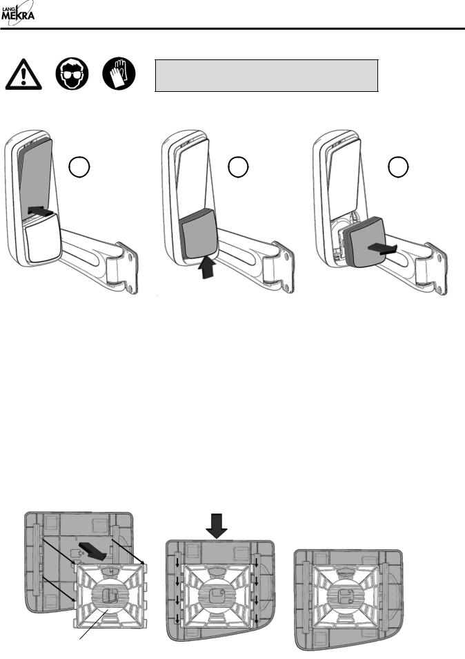
2.1. CONVEX MIRROR GLASS
1 |
2 |
3 |
Removal:
1.Push the main mirror inward at the bottom. (The actuator clutch will allow this manual adjustment of a motorized mirror) This will provide enough clearance in order to lift up on the convex mirror to disengage the tabs from the manual socket plate.
2. With the flat mirror pushed inward, push up on the convex mirror approximately ½” to disengage t on the convex carrier plate from the manual socket plate.
3.The convex mirror can now be removed from the mirror housing.
4.Disconnect the heating element wires from the heater foil terminals by pulling firmly on the wire connectors to completely free the convex mirror from the mirror assembly.
Installation: Install the replacement convex carrier assembly in the reverse operation of it being removed.
5.Inspect the condition of the heating element wires (corrosion, exposed wi connectors onto the heater foil terminals. If they are in good condition, then insert the connectors.
Note: The manual socket plate is fixed to the bezel. The illustrations shown below demonstrate how to carefully remove the glass carrier from the manual socket plate.
Fixed to bezel
Copyright © Lang Mekra North America 2014 |
Page 5 of 29 |
Revised: 03/2014

Peterbilt 579 - Mirrors - Service Manual
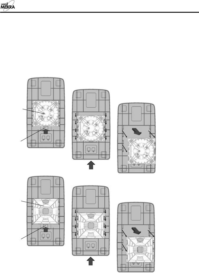
2.2. MAIN MIRROR GLASS
The flat mirror glass has the option of being removed with or without having the convex mirror removed. However, removal of the convex first will provide additional hand clearance to lift up on the flat glass during removal.
1 |
2 |
 Tab
Tab
Back view of main mirror glass carrier
3 |
4 |
5 |
|
|
Removal:
1.Push the main mirror glass inward at the top.
2.Insert hand from the bottom of glass and press tab down with fingers while pushing glass upwards to disengage tab.
3.Push the main mirror glass inward at the bottom.
4.Push the main mirror up approximately ½” to disengagetabs on the carriertheplate from the actuator / manual socket plate. (See note below.)
5.The main carrier glass can now be removed from the actuator / manual socket plate.
6.Disconnect the heating element wires from the heater foil terminals by pulling firmly on the wire connectors to completely free the main glass from the mirror assembly.
Copyright © Lang Mekra North America 2014 |
Page 6 of 29 |
Revised: 03/2014
Peterbilt 579 - Mirrors - Service Manual
Installation:
1.Install the main carrier assembly in the reverse operation of it being removed.
2.Inspect the condition of the heating element wires (corrosion, exposed wire, etc…) before inserting connectors onto the heater foil terminals. If they are in good condition, then insert the connectors.
Note: The actuator or manual socket plate is fixed to the bezel. The illustration shown below is to demonstrate how to carefully remove the glass carrier plate from the actuator/manual socket plate.
Actuator
Tab
Manual
Socket
Plate
Tab
Copyright © Lang Mekra North America 2014 |
Page 7 of 29 |
Revised: 03/2014

Peterbilt 579 - Mirrors - Service Manual
3. HOUSING (BACK COVER)
Removal:
1.Remove the main mirror glass (see 2.2).
2.The bezel is equipped with an opening and two molded-in thumb tabs located at the top of the mirror housing as shown in the figure. The opening will give your hand the needed space to push on the thumb tabs which will disengage the housing clips from the bezel tabs.
3.Push on the top two tabs until the housing clips are completely disengaged from the bezel tabs.
4.Once the top two tabs are disengaged, the lower clips will disengage from the bezel tabs by pulling the housing away from the arm.
Installation:
1.Position the housing at the back of the mirror.
2.Engage the bottom of the housing, making sure that the side walls of the housing are inside the lip of the bezel. Also ensure the OAT sensor is positioned correctly on the Left Hand Mirror.
3.Apply force onto the back cover until all the clips have engaged and the housing is seated correctly. Make sure that the side walls of the housing are inside the lip of the bezel.
Copyright © Lang Mekra North America 2014 |
Page 8 of 29 |
Revised: 03/2014
Peterbilt 579 - |
Mirrors - Service Manual |
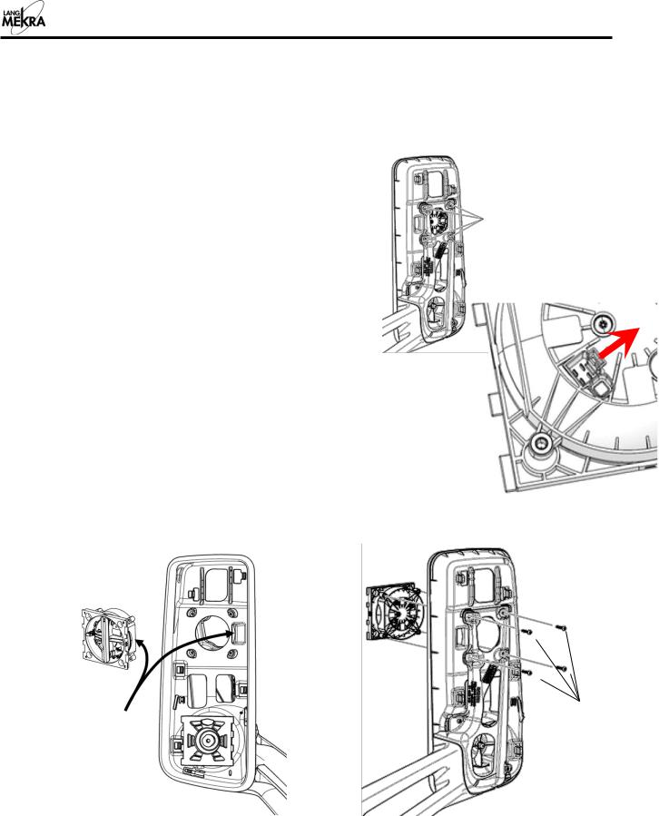
4. ACTUATOR |
|
Precautions: If you don’t have the proper tools for |
applying the torque shown |
become dysfunctional by applying the wrong torque. The actuators holes are a critical area and if a higher torque is applied, then the holes could fracture causing the actuator to become nonoperational.
Removal: |
|
0. Optional: Remove the mirror system from the truck (see 1). |
4 screws Torx T25 |
|
1.Remove the main glass (convex optional) (see 2.2).
2.Remove the housing (see 3).
3.To remove the actuator connector from the actuator, push the small locking lever on the actuator as shown, and pull the wire harness.
4.Remove the 4 Screws –Torx T25 from the back of the mirror.
Installation:
1.Position the actuator correctly. See figures below.
2.Install the 4 screws Torx T25 (torque 2.0 - 2.8 Nm).
3.Plug the actuator connector. Make sure it is secured with the lever.
4.Re-install the glass, housing and the mirror system on the truck (see 3, 2,1.)
Actuator Orientation
The Actuator flat side should match the Bezel feature. (facing the truck door)
Torque
2.0 - 2.8 Nm
Copyright © Lang Mekra North America 2014 |
Page 9 of 29 |
Revised: 03/2014
 Loading...