


387 prior
Table of contents
 Loading...

Quick Table of Contents
•Introduction.....................1
•Cab And Frame Access.........5
•Getting To Your Engine................8
•Controls And Displays...................... 10
•Seat And Restraint Systems ...................50
•Driver’s Checklists .......................................61
•Starting And Operating The Vehicle ....................65
•Mainten ance a nd Servi ce ...... ................. ................99
•Vehicle Identification.................................. ................ .....177
•Consumer Information...........................................................178
•Subject Index ...............................................................................180
California
Proposition 65 Warning
• Diesel engine exhaust and some of its constituents are
known to the State of California to cause cancer, birth
defects, and other reproductive harm.
• Other chemicals in this vehicle are also known to the
State of California to cause cancer, birth defects or
other reproductive harm.
• Battery posts, termi nals, and related accessor ies con-
tain lead and lead compounds, chemicals known to the
State of California to cause cancer and reproductive
harm. Wash hands after handling.

PART 1: INTRODUCTION
This manual contains useful information for the safe and efficient
operation of your Peterbilt Model 387 vehicle. It also provides information on maintaining your vehicle in the best condition, with an outline
for performing safety checks and basic preventive maintenance
inspections.
We have tried to present the information you’ll need to learn about
your vehicle’s fu nctions, controls, and operation - and to present it as
clearly as possible. We hope you’ll find this manual easy to use.
Please remember, though -- this manual is not a training manual. It
can’t tell you everything you need to know about driving your Peterbilt
vehicle. For that you need a good training program or truck driving
school. If you have not been trained, get the proper training before
you drive. Only qualified drivers should drive this vehicle.
There will be times when you need to take this manual out of your
Peterbilt. When you do, please be sure to return it to the cab when
you are finished using it. That way it will be there when you need it the
next time or when you pass the vehicle on to the next user.
How to Find What You Want
There are several tools built into this manual to help you find what y ou
need quickly and easily.
First is the Quick T ab le of Contents. Located at the front of the manual, this lists the main subjects covered and gives page numbers
where you can find these subjects. Use the Quick Table of Contents
to find information on a large subject like “Maintenance.”
Cross-referenced citations also help you get the information you
need. If some other part of the manual contains further information on
the subje ct you a re re ad ing abo ut, we’ll indic ate t hat in a cr oss -reference like this: (See PART 6: DRIVER’S CHECKLIST
to go searching for more information.
Finally you’ll find a helpful PART 11: SUBJECT INDEX
of the manual and al phabetically lists the subjects covered. So if you
want information on brakes, for example, just look under ”
the Subject Index. You’ll find all the pages listed where brakes or
braking are discussed.
). You won’t have
. It’s in the bac k
Brake" in
A Special Word about Repairs
Your Peterbilt dealer’s service center is the bes t place to have your
vehicle repaired. You can find Peterbilt dealers all over the country
with the equipment and trained personnel to get you back on the road
quickly - and keep you there.
Your vehicle is a complex machine. Anyone attempting repairs on it
needs good mechani cal training and the proper tools. If you are sure
you have these requirements, then you can probably perform some
repairs yourself. However, all warranty repairs must be performed by
an authorized Peterbilt service facility. If you aren’t an experienced
PB1328 —1— 22-02011 (R02/02)

PART 1: INTRODUCTION
mechanic, or don’t have the r ight equipm ent, plea se leave all repairs
to an authorized service facility. They are the ones equipped to do the
job safely and correctly.
WARNI NG! Attempting repair work without sufficient
training, service manuals, and the proper tools can be
dangerous. You could be injured or you could make
your truck unsafe. Do only those tasks you are fully
qualifie d to do.
Maintenance Manuals. If you do decide to do any complex repair
work, you’ll need the Peterbilt Maintenance manuals. Order them
from your authorized dealer. Please provide your Chassis Serial
Number when you order, to be sure you get the correct manuals for
your vehicle. Allow about four weeks for delivery. There will be a
charge for these manuals.
Final Chassis Bill of Material. A complete, nonillustrated computer
printout listing of the parts used to cust om -build your Peterbilt vehicle
is available through the Peterbilt dealer from whom your p urchased
your vehicle.
WARNI NG! Modifying your vehicle can make it unsafe.
Some modifications can affect your truck’s electrical
system, stability, or other important functions. Before
modifying your vehicle, check with your dealer to make
sure it can be done safely.
Additional Sources of Information
Operator’s manuals are also s upplied by the manuf act urers of components such as the engine, seats, transmission, and radio in your
Peterbilt. If you are missing any of thes e manuals, ask your Peterbilt
dealer to supply them.
Your Model 387’s glove box also contains a copy of the Truck
Driver’s Handbook, published by the American T rucking Association.
Refer to it for imp ortant information on driving your vehicle. Another
place to learn more about trucking is a local truck driving school. Contact one near you to find out what kinds of instruction it offers.
Federal and state agencies also have information you can ask for.
The Interstate Commerce Commission can give you information
about regulations governing transportation across state lines. And
various agencies in state governments are sources for regulations
that differ from state to state.
Warnings
We’ve put a number of warning messa ges in this manual. They are
there for your protection and information. Please read them and follow
them. They can help you to avoid injury to yourself and your passen-
PB1328 —2— 22-02011 (R02/02)
PART 1: INTRODUCTION
gers as well as to prevent costly damage t o your vehicle. We’ve used
certain symbol s and “signal words” to indicate what kind of m essage
is going to follow. When you see these symbols & words, you know
that you need to pay special attention. Please don’t ignore any of
these signal s.
WARNI NG!
When you see this symbol & word, the message that follows is especially vital. This signals something that can cause s erious injur y or
death. This message will tell you what the hazard is, what can happen
if you don’t heed the warning, and how to avoid it. For example:
WARNI NG! Attempting repair work without sufficient
training, service manuals, and the proper tools can be
dangerous. You could be injured or you could make
your vehicle unsafe. Do only those tasks you are fully
qualifie d to do.
CAUTION:
This symbol & word signals something that could damage your vehicle. And you might receive an injury, too. For example:
CAUTION: Continuing to operate a vehicle with insufficient oil pressure will cause serious engine damag e .
NOTE:
Gives you information we feel you’d l ike to have. It could have to do
with care of your vehicle or with driving more efficiently:
NOTE: A cold compressor can cause refrigerant to liquefy
and warp the valve plates or cause a hydraulic lock. Warm
the engine before starting the air conditioner.
PB1328 —3— 22-02011 (R02/02)

PART 1: INTRODUCTION
Please take the time to read the preceding messages when you see
them. And reme m ber:
WARNING! Something that could injure you seriously.
CAUTION: Something that could cause injury to you or your
vehicle.
NOTE: Useful information.
Vehicle Safety
Make sure your P eterbilt is in top working condition bef ore heading out on
the road—it is the
according to PART 6: DRIVER’S CHE CKLIST.
WARNING! Do not drink and drive. Your reflexes, perceptions, and judgment can be affected by even a small
amount of alcohol. Y ou could have a serious—or even fatal
accident—if you drive after drinking. Please do not drink
and drive or ride with a driver who has been drinking.
WARNING! The use of alcohol, drugs, and certain medications will seriously impair perception, reactions, and driving ability . These cir cumstances can substantiall y increase
the risk of an accident and personal injury.
Please remember, this manual is not a training manual. It cannot tell
you everything you need to know about driving your Peterbilt vehicle.
For that you need a good t raining program or truck d riving school. If
you have not been trained, get the proper training before you drive.
Only qualified drivers should drive this vehicle.
Every new Peterbilt vehicle is designed to conform to all Federal
Motor Vehicle Safety Standards applicable at the time of manufacture.
However, even with these safety features, continued safe and reliable
operation depends greatly upon regular vehicle maintenance. The
vehicle must be operated within the range of its mechanical capabilities and the limits of its load ratings. See the axle and tire load rating
information located on the driver’s door jamb.
responsible
driver's duty to do so. Inspect the vehicle
PB1328 —4— 22-02011 (R02/02)
PART 2: GETTING INTO AND OUT OF THE
CAB AND FRAME ACCESS
Be careful whenever you get into or out of your vehicle’s cab. Always
maintain at least three points of contact with your hands on the grab
handles and your feet on the steps.
WARNING! Jumping out of the cab or getting into the
cab without proper caution is dangerous. You could slip
and fall, possibly suffering a serious injury. Keep steps
clean. Clean any fuel, oil, or grease off of your shoes
and the steps before entering the cab. Use the steps
and grab handles provided, and always keep at least
three points of contact between your hands and feet and
the truck. Look where you are going.
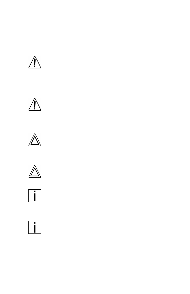
The illustrations below show the best ways to enter and exit a cab.
02958-A
Vehicle With Standard External Grab Handle
02958-B
Vehicle Without Standard External Grab Handle
PB1328 —5— 22-02011 (R02/02)

PART 2: GETTING INTO AND OUT OF THE
CAB AND FRAME ACCESS
Door Lock and Keys
Doors can be l ock ed f rom the inside by us ing the loc k button. Close the
door then push the button down to lock. Doors automatically unlock
when you open them from inside, and can be locked from the outside
with the k ey only.
WARNING! To lessen the chance and/or severity of personal injury in case of an accident, always lock the
doors while driving. Along with using the lap/shoulder
belts proper ly, locking the doors helps prevent occu pants from being thrown from the vehicle.
To lock or unlock the doors from outside the cab, insert the key in the
lock.Turn the key toward the rear to lock; forward to unlock.
Climbing Onto the Deck Plate
When you are climbin g onto and of f the deck plate, maintain a t least
three points of contac t with your hands on the grab ha ndles and your
feet on the steps.
WARNI NG!
•
You can be hurt if you aren’t careful climbing onto
and off the deck plate. You can slip and fall, especially if the surfaces are wet or icy, or if you step in
oil, fuel, or grease. Keep steps clean. Always maintain at least three points of contact between your
hands and feet and the steps and deck plate.
•
Do not climb onto and off the deckplate–use steps
and grabhandle provided. If there is no deck plate,
or if proper steps and grab handles aren’t provided,
don’t climb on t o t he ar ea behind the cab . Peter bi lt
did not intend for the area to be a step if handrails or
proper steps are not provided.
WARNI NG! Do not step on vehicle components without
antiskid surfaces or use components not designed for
entry-and-exit use . You could fall and injure yourself if
you step on a slippery surface. For example:
•
You cou ld fall and inj u r e yourself if you step onto a
fuel tank surface. A fuel tank is not a step. The tank
surface can get very slippery, and you might not be
able to prevent a fall. Don’t step onto the surface of a
fuel tank. Use only the step s and handholds provided,
not chain hooks, quarter fenders, etc.
•
Always reinstall steps before entering the cab or
accessing the deck plate. Without steps, you could
slip and fall, resulting in possible injury to yourself.
PB1328 —6— 22-02011 (R02/02)
PART 2: GETTING INTO AND OUT OF THE
CAB AND FRAME ACCESS
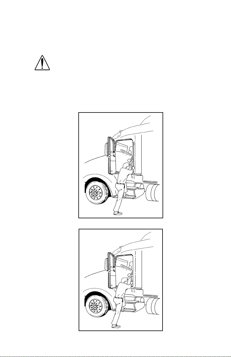
The pictures below show you the right way to get on and off the area
behind your cab.
NOTE: Any alteration (adding bulkheads, headache racks,
tool boxes, etc.) behind the cab or sleeper that affects the
utilizatio n o f grab ha nd les , de ck p lat e s, or fra m e acc es s
steps installed by Peterbilt must comply with FMCSR 399.
Hold handles as you step up Three points of contact
Three points of contact as you
reach the deck area
PB1328 —7— 22-02011 (R02/02)
Three points of contact as you
step to the deckplate
PART 3: GETTING TO YOUR ENGINE
Hood Tilt
Follow this procedure to tilt the hood.
WARNI NG! Before opening or cl osing the hood, be sure
there are no people or objects in the way. A hood could
hurt someone in the way of its opening or descent.
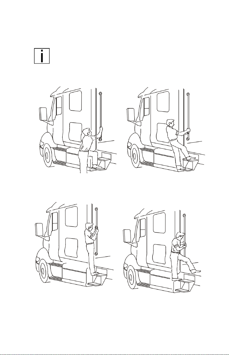
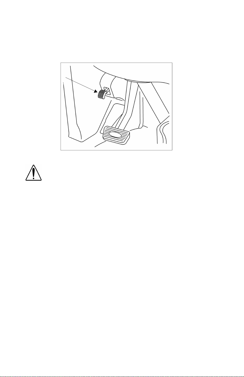
1. To open your hood, find the hood release ha ndle on the cab floor
beside the driver’s seat.
Hood
release
handle
2. Grasp the lever and turn it towards you. The hood will release and
pop open to a neutral position, approximately 2” above the closed
position.
PB1328 —8— 22-02011 (R02/02)

PART 3: GETTING TO YOUR ENGINE
WARNING! The hood uses hydraulic dampers to contr ol
movement du rin g opening. Do no t ti lt the hoo d wi t h
these dampers disconnected. Replace damaged, worn,
or leaking dampers as soon as possible. Tilting a hood
with the dampers disconnected or defective may cause
the hood to tilt too rapidly . You could be injured and the
hood coul d be damaged .
3. Proceed to the front of the vehicle and face the hood. Grasp the
hood ornament on the top of the crown molding. Pull forward and
down until the hood is fully open and rotation stops.
WARNING! If the hood falls, anyone under it could be
injured. Always ensure that a hood is fully tilted open
any time anyone gets under a hood for any reason.
4. To close the hood, firmly push upward and rearward on the hood
ornament to star t the hood tilting backwards. Continue to push
until the hood moves through its neutral position. The hood will
continue to tilt backwards. Apply a firm push to the hood ornament to engage the hood latches located on both sides of the firewall.
PB1328 —9— 22-02011 (R02/02)
PART 4: CONTROLS AND DISPLAYS
This par t explains t he locat ion of the various features on your vehicle
and describes their function. For information on using these features
in driving, see the paragraphs below.
Your Instrument Panel
Please remember that each Model 387 is custom-made. Your instr ument panel may not look exactly like the one in the pictures below.
We have tried to describe the most common features and controls
available, so your vehicle may not have some of the ones that appear
in this section. You can pick out the parts that apply to you and read
them to be fully informed on how your partic ular vehicle operates.
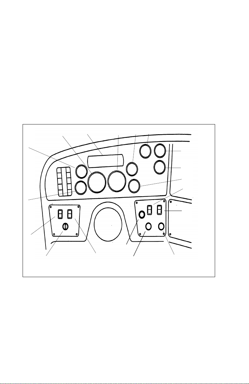
T y pical Cab Instruments and Control s
6
7
8
0
9
1
5
4
3
8
1
2
1
7
1
6
1
LEFT SIDE
1. ID/Clearan ce Lam ps Switch 10. Air Cleaner Restriction
2. Ignition Switch 11. Primary Air Pressure
3. Headlamps Switch 12. Secondary Air Pressure
4. Voltmeter 13. Fuel
5. Oil Pressure 14. SMC Select/Reset Switch
6. Tachometer 15. Dome Light Switch
7. Warning Light Bar 16. Windshield Wiper/Washer
8. Speedometer-Message Center (SMC) 17. Panel Dimmer
9. Water Temperature 18. Cigarette Lighter
1
1
2
1
3
1
4
1
5
1
B
1
7
9
2
0
PB1328 —10— 22-02011 (R02/02)
PART 4: CONTROLS AND DISPLAYS
12
11
10
9
14
13
8
15
16
17
7
6
5
20
21
4
3
2
1
02972A
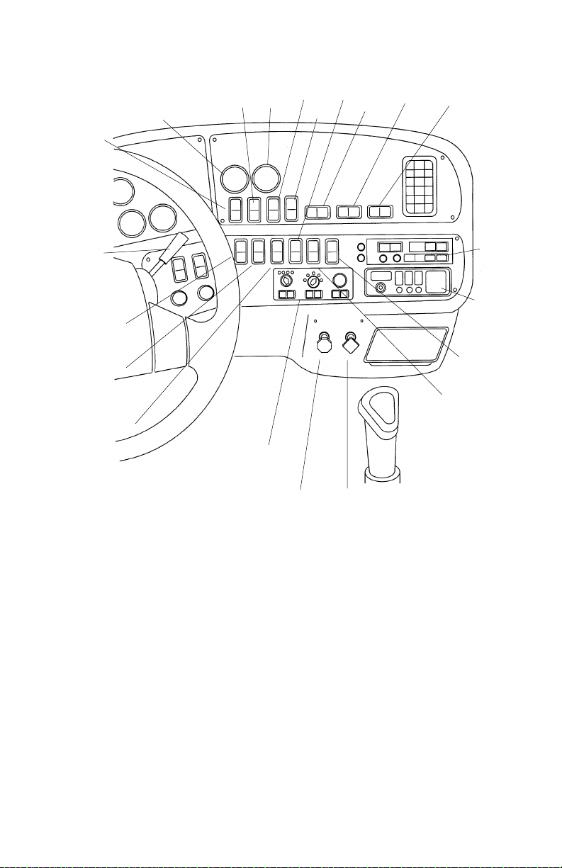
RIGHT SIDE
1. Parking Brake Valve 12. Engine Brak e
2. Trailer Air Suppl y Valve 13. Engine Brake
3. Heater/AC Control Panel 14. Load Lights Switch
4. Fog Lights Switch 15. Interaxle Differential Lock Switch
5. Engine Fan Switch 16. 5th Wheel Lock Switch
6. ID/Clearanc e Lamps Flash Switch 17. Air Suspension Switch
7. Trailer Brake Lever 18. Radio
8. Cruise Control Switch 19. CB Radio
9. Transmission Temperature 20. Selected Option Switch
10. Cruise Control Switch 21. Mirror Heater Switch
11. Pyrometer
18
19
PB1328 —11— 22-02011 (R02/02)
PART 4: CONTROLS AND DISPLAYS
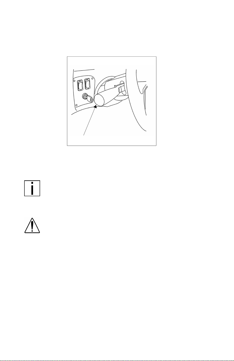
Steering Column-Mounted Controls
Turn Signal and Indicator Lights
02882C
Turn S igna l
Your turn signal lever is mounted on the left side of the steering column below the steering wheel. Green directional indicator lights
appear on the instrument panel.
NOTE: The ignition key must be turned to ON for the signal/
switch to operate.
To operate the signal, move the le ver in the direction of t he turn.
WARNING! After you complete a turn, shut the system off
by returning the le ver to the “OFF” (center) position. The
switch's lever action is NOT self-canceling. Failure to shut
off a turn signal could conf use other drivers and res ul t i n
an injury accident. An indicator light in the instrument
panel will flash until the turn signal is turned off.
PB1328 —12— 22-02011 (R02/02)
PART 4: CONTROLS AND DISPLAYS
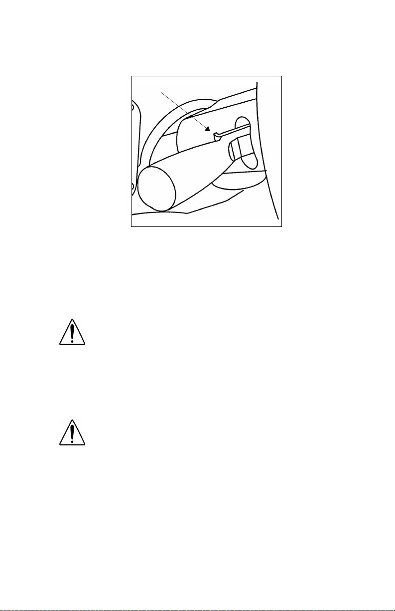
Hazard Flasher
02883B
Hazard Flasher
The four-way Hazard Flasher switch is on the turn signal body, just
underneath t he turn signal lever. It will operate with the key switch in
the ON or OFF pos ition. Use your hazard flasher whenever you are
off the road or on the side of the road, or in a potentially hazardous
situation. Pull it out to activate the system. All turn signals will flash at
once. To turn it o ff, m o ve th e turn si gnal leve r up or down.
WARNING! Use your Hazard Flasher Warning System any
time you have to stop off the road or on the side of the
road, day or night. A hard-to-see vehicle can result in an
injury accident. Another vehicle could run into you if you
do not set your flashers. Always move the vehicle a safe
distance off the road when stalled or stopped for repairs.
Of course, in normal stopping in traffic, such as at a stop light, you do
not use your flashers.
WARNI NG! Your disabled vehicle can be dangerous for
yo u an d ot h er s. Th e hot e xha u st sy st em co u ld ig ni te dry
grass, spilled fuel, or other substances. Do not park or
operate your vehicle where the exhaust system could
contact dry grass, brush, spilled fuel, or any other material that could cause a fire.
Air Horn
Your Model 387 has an air horn in addition to an electric horn. Control
the air horn by pul ling on the lanyard extending from the overhead
header panel.
PB1328 —13— 22-02011 (R02/02)
PART 4: CONTROLS AND DISPLAYS
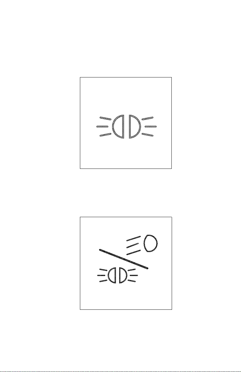
High Beam Headlights
02882C
High Beam Headlight Switch
All Peterbilt ve hicles come equipped with a combination turn sig nal and
high beam/low beam switch. To switch your headlights lower or higher,
gently pull the turn signal lever up , towards the st eering wheel , until you
hear the switch “c l i ck” and the beam changes .
Electric Horn
Your Peterbilt has an electric hor n. To sound the horn, press on the
bar in the center of the steering wheel
27884A
PB1328 —14— 22-02011 (R02/02)
PART 4: CONTROLS AND DISPLAYS
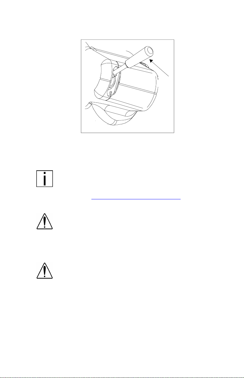
Trailer Br ake Hand Valve
02975A
This hand valve provides air pressure to apply the trailer brakes only.
It operates independently of the foot treadle valve.
To operate the trailer brake hand v al ve : pull down on t he lever under
the right side of the steering wheel.
NOTE: The trailer brake is not to be used as the main
means of braking. To use this brake frequently instead of
using the foot brake will wear out the trailer brake sooner.
See the Index, under Brake Safety and Emergency
plete information on when and how to use your trailer brake
79, for more com-
WARNI NG! It is dangerous to use air-applied trailer
brakes for parking or holding a vehicle. Air system pressure can bleed down and release the brakes. You could
have a vehicle roll-away resulting in an accident. You or
others could be badly injured. Always apply the parking
brakes for parking or holding your vehicle on grade.
WARNING! Grabbing the trailer brake hand lever
instead of the BrakeSaver lever could lead to an accident. If you have these levers, they may be close
together on your steering wheel column. Be sure you
get the one you want. The BrakeSaver lever is bent,
while the trailer parking brake lever is straight.
PB1328 —15— 22-02011 (R02/02)
PART 4: CONTROLS AND DISPLAYS
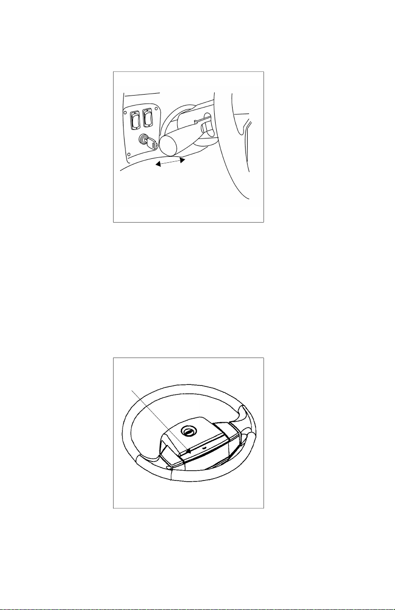
Tilt-Telescoping Steering Column
The telescoping feature of the steering wheel allows forward and rearward movement of the wheel. The tilting feature allows you to move
the wheel up and down.
Tilt-Telescope Lever
WARNING! Adjusting the Tilt-Telescoping Steering
Wheel while the vehicle is in motion could cause loss of
control. You would not be able to steer properly and
could have an accident. Make all adjustments to the
steering mechanism while the vehicle is stopped.
To position the wheel: Locate the Tilt-Telesc ope Lever on the floor,
to the left of the steering column. Push this lever toward the floor.
Move the steering wheel to the desired angle and height. Release the
lever to lock in the correct position.
PB1328 —16— 22-02011 (R02/02)

PART 4: CONTROLS AND DISPLAYS
Dash-Mounted Features
Keys and Locks
The same key fits your ignition, doors, and sleeper luggage compar tment. Frame-mounted tool box locks, locking fuel tank caps, and
glove boxes each have individual keys.
Ignition Switch
Your ignition switch has four positions:
OFF
ACC ONLY
IGN & ACC
START
02977A
ACC (Accessory): With your key in this position you can play the
radio or use other accessories, but your engine
won’t start.
OFF: In this position all systems are off, and you can
remove yo ur key.
IGN & ACC: This position allows you to turn on the engine
and all accessory power.
START: Starter activation to start engine.
PB1328 —17— 22-02011 (R02/02)
PART 4: CONTROLS AND DISPLAYS
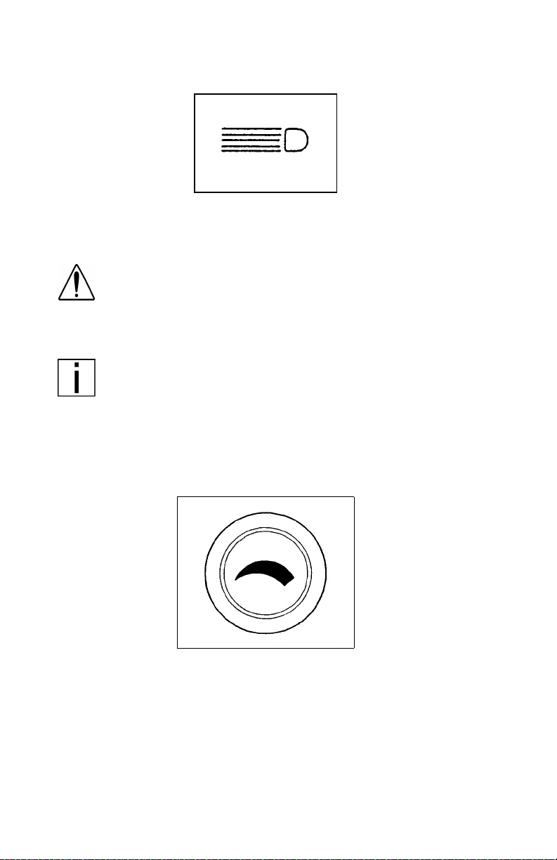
Headlights
02890
The headlights are controlled by the control panel switch showing this
symbol. When the headlights are ON, the das h lights, side, and tail
lamps are also on.
WARNING! Do not use daytime running lights (DRL)
during pe rio ds of darkness or reduced visibility. Do not
use DRL as a substitute for headlights or other lights
during operations that require lighting of your vehicle.
Doing so could lead to an injury accident.
NOTE: On vehicles equipped with daytime running lights
(DRL), the inboard park-and-turn lamps go on automatically
at reduced brightness if the engine is running and the headlamp switch is turned off. The daytime running lights are
turned off automatically while the parking brake is engaged.
If the headlamp switch is turned on, the DRL system is overridden & headlamps operate normally.
Panel Light Knob
02891
The Panel Light Knob lets you vary the bri ghtness of your instrument
panel lights.
To Operate Your Panel Light Knob:
1. Tur n on either the headlights, clearance lights, or fog/driving lights
with IGN on.
2. To brighten the instrument panel lights, turn the knob clockwise (to
the right).
3. To dim the instrument lights or to turn them off, turn the knob counterclockw ise (to th e left ) .
PB1328 —18— 22-02011 (R02/02)
PART 4: CONTROLS AND DISPLAYS
ID and Clearance Lights Switches
These are the amber lights on top of your cab, the lights on the front
and sides of the trailer and the red lights on the rear of a t ruck or trailer.
They may be turned on and off by the switch located on the lower left
control panel labeled CL LPS and showing the symbol below.
02892
When your clearance lights are turned on, you may blink or flash them
by operating the flash switch located on the right side of the dash
showing the symbol be low. Press and release this rocker switch to
flash your clearance lights.
03912-1
PB1328 —19— 22-02011 (R02/02)
PART 4: CONTROLS AND DISPLAYS
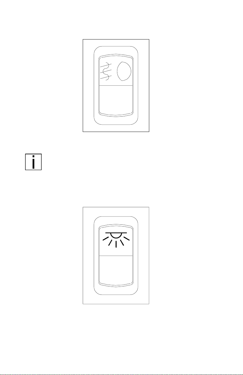
Fog/ Driving Lights Switch
I
O
03021
If your vehicle has fog/driving lights, turn them ON or OFF with the
control panel switch shown above.
NOTE: State requirements vary as to when high beams and
fog lights can and cannot be used together. Further, some
states allow only four lights to be used together; some allow
more. Whether you have dual or composite lights will affect
how many lights you can have on at one time. Always comply with the state requirements where you are driving.
Dome Light Switch
I
O
02894A
A momentary switch controls the main dome light:
• OFF (O) Position: Light is off.
• ON (I) Position:
-Press once: Light will turn on at high intensity.
-Press again: Light will shift to low intens it y.
-Press a third time: Light will turn off.
PB1328 —20— 22-02011 (R02/02)
PART 4: CONTROLS AND DISPLAYS
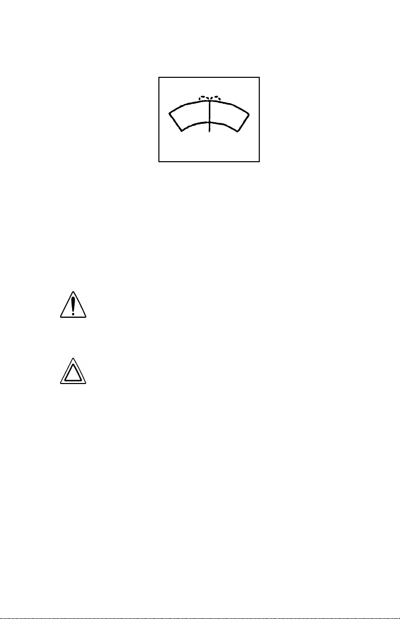
Windshield Wipers and Washer s
02896
Wiper
To turn on the wipers rotate the knob to the right. As the knob is
rotated, the speed of the wipers increases. To turn off the wipers,
rotate the knob to the left.
Washer
To use the washer, pus h the knob showing the symbol above. With
the electric wipers, the wipers will come on for a short time when the
washer starts.
WARNING! Do not drive with worn or dirty wiper blades.
They can reduce visibility, making driving hazardous.
Clean blades regularly to remove road film and wax buildup. Use an alcohol-based cleaning solution and a lint-free
cloth, and wipe along the blades.
CAUTION: Do not use antifreeze or engine coolant in the
windshield washer reservoir—damage to seals and other
components will result.
Intermittent Windshield Wiper Control
Two-speed intermittent windshield wipers are controlled by the control
panel knob with the symbol shown above. To turn on the wipers,
rotate the knob to the right.
As you turn the knob further to the right, inter m ittent delay decreases
until the knob encounters the first position for continuous operation.
Turn the knob further right to the next position fo r higher speed continuous operation. Turn off the wipers by rotating the knob to the left.
PB1328 —21— 22-02011 (R02/02)
PART 4: CONTROLS AND DISPLAYS
Air Suspension Deflate Switch (Dump Valve)
AIR SUSPENSION
03035
Your Model 387 may have an air suspension deflation switch that
allows the air in the suspension to be exhausted fr om a switch on the
dash. The purpose of this feature i s t o allow you to lower your tractor
to get under a trailer.
You will notice a gu ard over the switch. This prevents you from accidentally deflating the suspension.
WARNI NG! Operating the Air Suspension Deflate
Switch (Dump Valve) while driving can lead to an accident. Sudden deflation while your vehicle is moving can
affect hand li ng an d control. Use this switc h on ly when
your vehicle is not moving.
CAUTION: Operating a vehicle with air suspension bags
either overinflated or underinflated may cause damage
to driveline components. If a vehicle must be operated
under such conditions, do not exceed 5 mph.
PB1328 —22— 22-02011 (R02/02)
PART 4: CONTROLS AND DISPLAYS
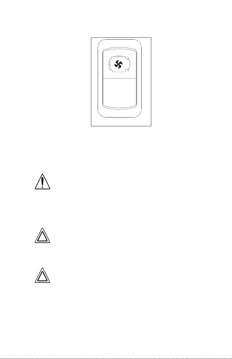
Engine Fan Switch
I
0
03023
The engine fan switch allows you to control the engine fan manually
or automatically. With the ignition key switch ON and the fan switch in
the ON position, the e ngine fan will be on regardless of engine temperature. With the engine fan switch in the AUTOMAT IC position, th e
engine fan will automatically turn on when the engine coolant reaches
a temperature of about 200
WARNING! Do not work on the fan with the engine running. Anyone near the engine fan when it turns on could
be badly injured. If it is set at ON, it will turn on any time
the ignition key switch is turned to the ON position. In
AU T O MATIC, i t coul d e ng age sud d enl y wi th ou t wa rni ng .
Before turning on t he i gni t io n or switching from AUTOMATIC to ON, be sure no one is near the fan.
°F.
CAUTION: The fan or equi pm ent near it co ul d be dam -
aged if the fan turns on suddenly when you don’t expect
it. Keep all tools and equipment such as rags away from
the fan, and take care no one turns on the ignition when
someone is working near the fan.
CAUTION: Do not op era te the engine fan in th e manual
(ON) position for e xtended perio ds of ti me. The fan hub
was designed for intermittent operation. Sustained
operation will shorten the fan hub’s service life as well
as reduce fuel economy.
PB1328 —23— 22-02011 (R02/02)

PART 4: CONTROLS AND DISPLAYS
Mirro r Heat Switch
I
O
03022
Mirror heat is controlled by the control panel switch shown above. If
the vehicle is equipped with this switch, mirror heat can be switched
on to help remove frost and ice from the mirror glass.
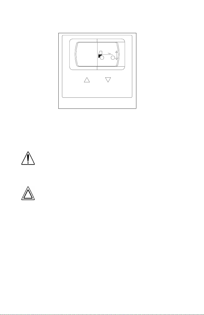
Pow er Mirr or Switch
WARNING! Convex mirrors can distort images and make
objects appear smaller and farther away than they really
are. You could have an accident if you are too close to
another vehicle or other object. Keep plenty of space
between your vehicle and others when you turn or change
lanes. Remember that other objects are closer than they
may appear.
The power mirror control cont rols the adjustment of the r ight or left
outside mirrors, depending on the option select ed. It is located in th e
driver side armrest.
NOTE: The Power Mirror Switch does not control the adjustment of the convex mirrors.
PB1328 —24— 22-02011 (R02/02)
PART 4: CONTROLS AND DISPLAYS
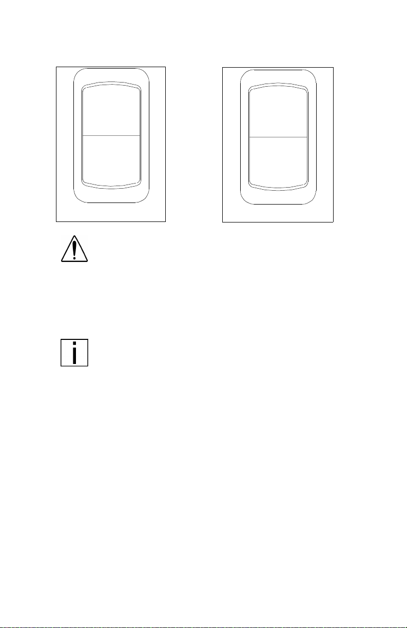
CRUISE
ON/OFF
I
0
03025
Cruise Control Switch
SET
CRUISE
SELECT
RESET
03026
WARNING! Do not operate the cruise control when operating on road surfaces with poor traction (wet, icy, or snow
covered roads) or in heavy traffic. Accelerations caused by
the normal operation of the cruise control could cause you
to lose control of the vehicle resulting in an injury accident.
The master switch turns t he cruise control ON or OFF. The second
switch allows you to SET the desired speed or RESET the desired
speed after the cruise control function has been interrupted.
NOTE: Cruise control functions and features may vary
depending upon which engine you have. For specific explanation of your cruise control, see the cruise control or engine
manual included with your vehicle.
PB1328 —25— 22-02011 (R02/02)

PART 4: CONTROLS AND DISPLAYS
Digital Message Center
ENTER
∨
∨
DIAG
TRIP
°
FUEL
∨
SENSOR
°
CLOCK
MAINT
INFO
RESET MSG
∨
CANCEL
03038
The optional digital mess age center (DMC) is an onboard computer
used to provide the following:
• trip inform a ti on
• clock/calendar
• fuel economy
• sensor data
• fault codes
• maintenance information
• warning messages
The DMC vacuum-fluorescent display is capable of displaying 40
characters. Navigation through the information is done by means of
an integral keypad. Refer to the DMC operator’s manual that came
with the vehicle for more information on using this component.
PB1328 —26— 22-02011 (R02/02)
PART 4: CONTROLS AND DISPLAYS
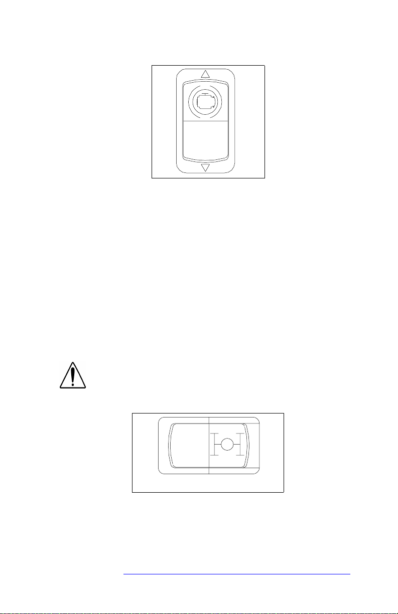
Engine Brake
03028
When an eng ine brake is ene rgized, the power-produc ing dies el eng ine
is converted into a power-absorbing air compressor to retard the vehicle.
• The brake is energized whenever the driver’s foot is completely
removed from the accelerator pedal.
• The brake is deenergized during driving by pressure on the accel-
erator pedal, and during shifting by depressing the clutch pedal.
The ON/OFF toggle switch turns the system ON or OFF.
• In Caterpillar- and Cum mi ns- powered vehicles equipped w ith a
Jacobs Engine Brake, a second two- or three-mode switch is incorporated in the instrument panel. With this system, you can select
either LOW or HIGH or LOW/MEDIUM/HIGH retarding.
For more information on when and how to use the engine brake in
your vehicle, see the owner’s manual for the engine brake.
WARNING! Using the engine brake when operating on
surfaces with poor traction (such as wet or icy, slipp ery
roads or gravel) could cause loss of control.
Two-Speed Rear Axle (Range) Switch
2
03030
If your vehicle is equipped with a t wo-speed rear axle, you can select
the axle range by the dash mounted switch shown above.
• The low range provides maximum torque for operating off-highway .
• The high range is a faster ratio for highway speeds.
For information on how to operate your two-speed rear axle properly
and safely, see PART 7: STARTING & OPERATING THE VEHICLE
PB1328 —27— 22-02011 (R02/02)
.
PART 4: CONTROLS AND DISPLAYS
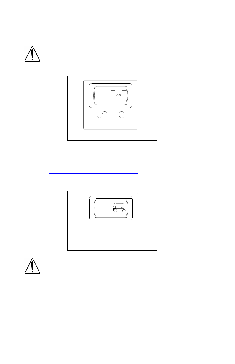
Interaxl e D i ffer en tial Lock Swi tch
WARNING! Placing the differential lock in the “LOCK”
position while y our wheels ar e spinning c ould cause loss
of control or axle damage. You could be hurt. Switch to
“LOCK” only when your wheels are not spinning.
SHIFT AT ANY SPEED EXCEPT
IF A WHEEL IS SPINNING
03029
The interaxle differential allows differential action between the forward
rear and the rear rear driving axles. The interaxle differential lock
switch allows the operator to LOCK or UNLOCK the differential. The
guard over this switch preve nts you from accidentally activating the
lock. See “
using your interaxle differential.
Fifth Wheel Lock (Slider Adjustment) Switch
Inter axle Differ ential ” on page 72 for mo re information on
WARNI NG!
Do not move of the fifth wheel while the trac-
tor-trailer is in motion.
0
CAB CONTROL
1
03031
Movement of the fifth wheel while
a tractor-trailer is moving can cause a serious accident.
Yo ur load could shi f t sudd enly, causing you to lose control of the vehicle. Never operate the vehicle with the
switch in the unlock position. Always inspect the fifth
wheel after you lock the switch to be sure the fifth wheel
is engaged
Vehicles having an air slide fifth wheel have a fifth wheel slider lock
controlled by a switch on the instrument panel. By placing the switch
in the unlock position, you can slide the fifth wheel to various positions to adjust weight distribution. There i s a guard over this switch to
protect you against accidentally activating or releasing the lock.
PB1328 —28— 22-02011 (R02/02)
Loading...