


Model 520
Body Builder Manual
2019
Release Date 7/30/19
This page intentionally left blank

BODY BUILDER MANUAL CONTENTS
SECTION 1: INTRODUCTION |
1-1 |
SECTION 2: SAFETY AND COMPLIANCE |
|
SAFETY SIGNALS |
2-1 |
FEDERAL MOTOR VEHICLE SAFETY STANDARDS AND COMPLIANCE |
2-2 |
NOISE AND EMISSIONS REQUIREMENTS |
2-3 |
FUEL SYSTEM |
2-4 |
COMPRESSED AIR SYSTEM |
2-4 |
EXHAUST AND EXHAUST AFTER-TREATMENT SYSTEM |
2-5 |
COOLING SYSTEM |
2-6 |
AIR INTAKE SYSTEM |
2-6 |
CHARGE AIR COOLER SYSTEM |
2-6 |
SECTION 3: DIMENSIONS |
|
INTRODUCTION |
3-1 |
ABBREVIATIONS |
3-1 |
OVERALL DIMENSIONS |
3-2 |
FRAME RAILS |
3-9 |
FRAME HEIGHT CHARTS |
3-11 |
REAR SUSPENSION LAYOUTS |
3-18 |
Reyco 79KB Single |
3-19 |
Reyco 102AR Single |
3-20 |
Neway ADZ252 |
3-21 |
Neway ADZ369/378 |
3-22 |
Peterbilt Air Leaf |
3-23 |
Peterbilt Air Trac Single |
3-24 |
Peterbilt Air Trac Tandem |
3-25 |
Peterbilt Air Trac Tri-Drive |
3-26 |
Peterbilt Low Air Leaf |
3-27 |
Chalmers 854 |
3-28 |
Hendrickson HMX |
3-29 |
Hendrickson RT/RTE |
3-30 |
Hendrickson HN |
3-31 |
Hendrickson R |
3-32 |
Hendrickson RS |
3-33 |
PUSHER AND TAG LAYOUTS |
3-34 |
Hendrickson |
3-34 |
Watson-Chalin |
3-38 |
EXHAUST HEIGHT CALCULATIONS |
3-42 |
GROUND CLEARANCE CALCULATIONS |
3-43 |
OVERALL CAB HEIGHT CALCULATIONS |
3-44 |
FRAME COMPONENTS |
3-45 |
Fuel Tanks |
3-45 |
EXHAUST SYSTEM |
3-46 |
SECTION 4: BODY MOUNTING |
|
INTRODUCTION |
4-1 |
FRAME RAILS |
4-1 |
CRITICAL CLEARANCES |
4-2 |
BODY MOUNTING USING BRACKETS |
4-3 |
Brackets |
4-4 |
Mounting Holes |
4-5 |
Frame Drilling |
4-6 |
|
|
|
|
Peterbilt Motors Company |
ii |
BODY MOUNTING USING U–BOLTS |
4-7 |
Rear Body Mount |
4-9 |
SECTION 5: FRAME MODIFICATIONS |
|
INTRODUCTION |
5-1 |
DRILLING RAILS |
5-1 |
MODIFYING FRAME LENGTH |
5-2 |
CHANGING WHEELBASE |
5-2 |
CROSSMEMBERS |
5-3 |
TORQUE REQUIREMENTS |
5-4 |
SECTION 6: ELECTRICAL 520 FAMILY |
|
CONTROL UNIT IDENTIFICATION |
6-1 |
Functional Description-Cab Electronic Control Unit (CECU) |
6-1 |
HOW MULTIPLEXED INSTRUMENTS WORK |
6-2 |
CECU Architecture |
6-2 |
Power On Self-Test |
6-3 |
ELECTRICAL INTERFACE |
6-4 |
Cab Harness |
6-4 |
Chassis Harness |
6-9 |
Body Builder Harness Extensions |
6-10 |
Optional Body Builder PTO Module |
6-10 |
J1939 |
6-13 |
Guidelines - J1939 Circuit Requirements |
6-13 |
J1939 Access |
6-13 |
J1939 Access Procedures |
6-13 |
SECTION 7: PTO SECTION |
|
INTRODUCTION |
7-1 |
TRANSMISSION MOUTED PTO – GENERAL |
7-1 |
Manual Transmission |
7-1 |
Automatic Transmission |
7-2 |
Installation Clearances |
7-2 |
FRONT ENGINE PTO |
7-3 |
REAR ENGINE PTO |
7-4 |
PTO INSTALLATIONS |
7-5 |
REMOTE PTO CONTROL (12 PIN CONNECTOR) |
7-6 |
Cummins Remote PTO Operation |
7-6 |
INSTALLATION OF PTO MODEL |
7-7 |
Chelsea 890 |
7-7 |
OPTIONAL PTO FUNCTION MODULE |
7-8 |
APPENDICES: |
|
REVISION LOG |
A1 |
|
|
Peterbilt Motors Company |
iii |

SECTION 1 INTRODUCTION
The Peterbilt 520 Body Builder Manual was designed to provide body builders with a comprehensive information set to guide the body planning and installation process. Use this information when installing bodies or other associated equipment.
This manual contains appropriate dimensional information, guidelines for mounting bodies, modifying frames, electrical wiring information, and other information useful in the body installation process.
The Peterbilt 520 Body Builder Manual can be very useful when specifying a vehicle, particularly when the body builder is involved in the vehicle definition and ordering process. Information in this manual will help reduce overall costs through optimized integration of the body installation with vehicle selection. Early in the process, professional body builders can often contribute valuable information that reduces the ultimate cost of the body installation.
In the interest of continuing product development, Peterbilt reserves the right to change specifications or products at any time without prior notice. It is the responsibility of the user to ensure that he is working with the latest released information. Check Peterbilt.com for the latest released version.
If you require additional information or reference materials, please contact your local Peterbilt dealer.
|
|
Peterbilt Motors Company |
1-1 |
This page intentionally left blank

SAFETY AND COMPLIANCE |
2 |
SECTION 2 SAFETY AND COMPLIANCE
SAFETY SIGNALS
We’ve put a number of alerting messages in this book. Please read and follow them. They are there for your protection and information. These alerting messages can help you avoid injury to yourself or others and help prevent costly damage to the vehicle.
Key symbols and “signal words” are used to indicate what kind of message is going to follow. Pay special attention to comments prefaced by “WARNING”, “CAUTION”, and “NOTE.” Please don’t ignore any of these alerts.
Warnings, cautions, and notes
WARNING
Example:
When you see this word and symbol, the message that follows is especially vital. It signals a potentially hazardous situation which, if not avoided, could result in death or serious injury. This message will tell you what the hazard is, what can happen if you don’t heed the warning, and how to avoid it.
WARNING! Be sure to use a circuit breaker designed to meet liftgate amperage requirements. An incorrectly specified circuit breaker could result in an electrical overload or fire situation. Follow the liftgate installation instructions and use a circuit breaker with the recommended capacity.
CAUTION
Signals a potentially hazardous situation which, if not avoided, could result in minor or moderate injury or damage to the vehicle.
Example:
CAUTION: Never use a torch to make a hole in the rail. Use the appropriate drill bit.
NOTE
Provides general information: for example, the note could warn you on how to avoid damaging your vehicle or how to drive the vehicle more efficiently.
Example:
Note: Be sure to provide maintenance access to the battery box and fuel tank fill neck.
Please take the time to read these messages when you see them, and remember:
WARNING
Indicates a potentially hazardous situation which, if not avoided, could result in death or serious injury.
CAUTION
Signals a potentially hazardous situation which, if not avoided, could result in minor or moderate injury or damage to the vehicle.
NOTE
Useful information that is related to the topic being discussed.
SAFETY AND COMPLIANCE |
2 |
FEDERAL MOTOR VEHICLE SAFETY STANDARDS AND COMPLIANCE
As an Original Equipment Manufacturer, Peterbilt Motors Company. ensures that our products comply with all applicable U.S. or Canadian Federal Motor Vehicle Safety Standards. However, the fact that this vehicle has no fifth wheel and that a Body Builder (Intermediate or Final Stage Manufacturer) will be doing additional modifications means that the vehicle was incomplete when it left the build plant.
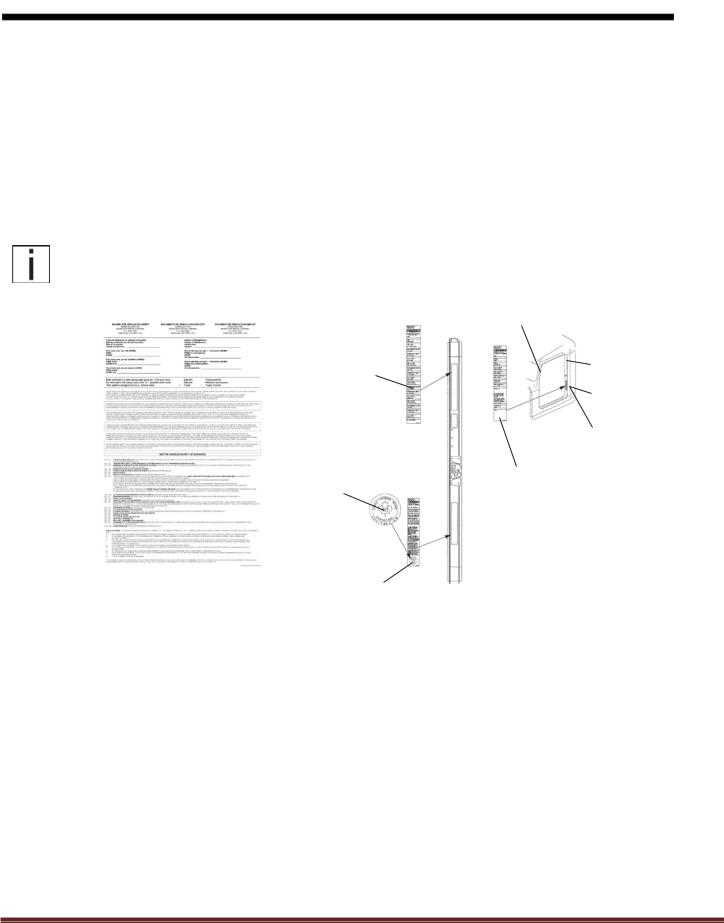
Incomplete Vehicle Certification
An Incomplete Vehicle Document is shipped with the vehicle, certifying that the vehicle is not complete. See Figure 2–1. In addition, affixed to the driver’s side door frame or edge is an Incomplete Vehicle Certification label. See Figure 2–2.
NOTE |
These documents list the U.S. or Canadian Federal Motor Vehicle Safety Standard regulations that the |
|
vehicle complied with when it left the build plant. You should be aware that if you add, modify or alter any |
|
of the components or systems covered by these regulations, it is your responsibility as the Intermediate or |
|
Final Stage Manufacturer to ensure that the complete vehicle is in compliance with the particular |
|
regulations upon completion of the modifications. |
Tire, Rim and
Weight Rating
Data label
Safety Mark (Canadian
Registry Only)
U.S. EPA Noise Label (U.S. registered vehicles only)
Final Stage Manufacturer
Label to be installed by
Final Stage Manufacturer
Chassis Serial
Number
Vehicle Emission Control
Information Label
Major Components and
Weights Label
Incomplete Vehicle |
|
FIGURE 2-1. Incomplete Ve- Certification Label |
FIGURE 2-2. Locations of Certifica- |
hicle Certification Document |
tion Labels - Driver’s Door and Frame |
As the Intermediate or Final Stage Manufacturer, you should retain the Incomplete Vehicle Document for your records. In addition, you should record and retain the manufacturer and serial number of the tires on the vehicle. Upon completion of the vehicle (installation of the body and any other modifications), you should affix your certification label to the vehicle as required by Federal law. This tag identifies you as the “Intermediate or Final Stage Manufacturer” and certifies that the vehicle complies with Federal Motor Vehicle Safety Standards. (See Figure 2–2.) Be advised that regulations affecting the intermediate and final stage manufacturer may change without notice. Ensure you are referencing the most updated copy of the regulation during the certification and documentation processes.
In part, if the final stage manufacturer can complete and certify the vehicle within the instruction in the incomplete vehicle document (IVD) the certification label would need a statement that reads, “This vehicle has been completed in accordance with the prior manufacturers‚ IVD where applicable. This vehicle conforms to all applicable Federal Motor Vehicle Safety Standards [and Bumper and Theft Prevention Standards if applicable] in effect in (month, year).”
However, if the vehicle cannot be completed and certified with in the guidance provided in the IVD, the final stage manufacturer must ensure the vehicle conforms to all applicable Federal Motor Vehicle Safety Standards (FMVSS). The final stage manufactures certification label would need a statement that reads, “This vehicle conforms to all applicable Federal Motor Vehicle Safety Standards [and Bumper and Theft Prevention Standards if applicable] in effect in (month,
Peterbilt Motors Company |
2-2 |

SAFETY AND COMPLIANCE |
2 |
year).These statements are just part of the changes to the new certification regulation. Please refer to the Feb 15, 2005 final rule for all of the details related to this regulation. You can contact NTEA Technical Services Department at 1-800- 441NTEA for a copy of the final rule (DocID 101760).
For Canadian final stage manufacturers see:
http://www.gazette.gc.ca/index-eng.html;
and http://www.tc.gc.ca/eng/acts-regulations/menu.htm for the regulations.
Or contact: Transport Canada
Tower C, Place de Ville, 330 Sparks Street Ottawa, Ontario K1A
0N5 (613) 990-2309 TTY: 1-888-675-6863
Noise and Emissions Requirements
NOTE
This truck may be equipped with specific emissions control components/systems* in order to
meet applicable Federal and California noise and exhaust emissions requirements. Tampering with these emissions control components/systems* is against the rules that are established by the
U.S Code of Federal Regulations, Environment Canada Regulations and California Air Resources Board (CARB). These emissions control components/systems* may only be replaced with original equipment parts.
Additionally, most vehicles in North America will be equipped with a Greenhouse Gas (GHG) “Vehicle Emission Control Information” door label indicating its certified configuration. The vehicle components listed on this label are considered emission control devices.
Modifying (i.e. altering, substituting, relocating) any of the emissions control components/systems defined above will affect the noise and emissions performance/certification. Modifications that alter the overall shape and aerodynamic performance of a tractor will also affect the emission certification. If modifications are required, they must first be approved by the manufacturer. Unapproved modifications could negatively affect emissions performance/certification. There is no guarantee that proposed modifications will be approved.
Tires may be substituted provided the new tires possess a Coefficient of rolling resistance (Crr) equal to or lower than Crr of the original tires. Consult with your tire supplier(s) for appropriate replacement tires.
Contact the engine manufacturer for any requirements and restrictions prior to any modifications.
•For Cummins Contact 1-800-DIESELS or your local Cummins distributor. Reference AEB 21.102.
It is possible to relocate the DEF tank; however the relocation requirements need to be followed. Any variances from the relocation requirements may cause the emissions control components/systems to operate improperly potentially resulting in engine de-rate.
Peterbilt Motors Company |
2-3 |

SAFETY AND COMPLIANCE |
2 |
NOTE
All 2017 engine emissions certified vehicles will be equipped with an On-Board Diagnostics (OBD)
system. The OBD system is designed to detect malfunctions of any engine or vehicle component that may increase exhaust emissions or interfere with the proper performance of the OBD system itself All diesel engines will be equipped with an On-Board Diagnostics (OBD)
system. The OBD system consists of computer program on one or more of the vehicle’s Electronic Control Units (ECUs). This program uses information from the control system and from additional sensors to detect malfunctions. When a malfunction is detected, information is stored in the ECU(s) for diagnostic purposes. A Malfunction Indicator Light (MIL) is illuminated in the dash to alert the driver of the need for service of an emission-related component or system.
To ensure compliance to emissions regulations, the final configuration of certain features of the completed vehicle must meet specific requirements. This section describes requirements relevant for only the most common or critical modifications done by body builders. For a complete description of acceptable modifications, see the application guidance available from the manufacturer of the engine installed in the chassis.
Fuel System
The following are highlights of some of the more common or critical aspects of this system.
The overall system restriction may not exceed the restriction limitations set forth by the engine manufacturer for both supply and return.
•Ensure that fuel lines are not pinched or can potentially be damaged when installed between body and frame
•Fuel lines must be routed and secured without dips or sags
•There must be easy access to filter(s) and fill cap
•The tank vent may not obstructed
•Added accessories (heaters, generators) cannot introduce air into system
•Fuel tank must be located so that the full level is not above cylinder head
•“Ultra-Low Sulfur Fuel Only” labels must be present on the dash and fuel fill
•Modification of the pressure side secondary filter and plumbing is not allowed without engine manufacturer approval
•Body installation of fuel tank or routing of lines must not cause significant increase in fuel temperature
•Fuel hoses shall meet or exceed OEM supplied hose material construction specifications
Compressed Air System
The following are highlights of some of the more common or critical aspects of this system.
•Air system modification must meet applicable FMVSS regulations
•Compressed Air tank may not be modified (exception – addition or removal of fittings or relocation of the tank)
•Added devices or bodywork may not interfere with or rub air lines
Peterbilt Motors Company |
2-4 |
SAFETY AND COMPLIANCE |
2 |
•Air supply to the engine doser may not be restricted or disconnected
•Air lines should be routed, protected from heat, and properly secured to prevent damage from other components
•Care should be taken so that air lines do not rub against other components
•Care should be taken to protect the air system from heat sources
Exhaust and Exhaust After-treatment System
The following are highlights of some of the more common or critical aspects of this system.
•The following after-treatment and exhaust system components may not be modified:
•DPF assembly
•SCR Catalyst assembly
•Exhaust pipes between the engine and after-treatment devices (DPF, SCR Catalyst) and between after-treatment devices
•NOx Sensors
•PM Sensor
•The following modifications may only be done within the guidelines of the “DEF System Relocation Guide.”
•Modifications to Diesel Exhaust Fluid (DEF) throttle, suction, or pressure lines
•Modification or relocation of the DEF tank
•Modification of coolant lines to and from the DEF tank
•All DEF and coolant lines should be routed, protected, and properly secured to prevent damage during vehicle operation or other components
•If relocation of the DCU or ACM is necessary, use existing frame brackets and mount inside of frame flanges where necessary. Do not extend the harnesses
•The DPF, the SCR catalyst, or their mounting may not be modified
•The NOx sensor may not be relocated or altered in any way; this includes re-clocking the aftertreatement canister or reorienting the sensor(s)
•Exhaust pipes used for tailpipes/stacks must be properly sized, and must prevent water from entering
•Ensure adequate clearance between the exhaust and body panels, hoses, and wire harnesses
•The body in the vicinity of the DPF must be able to withstand temperatures up to 400°C (750°F)
•Do not add thermal insulation to the external surface of the DPF
•The SCR water drain hole may not be blocked
•Allow adequate clearance (25mm (1 inch)) for servicing the DPF sensors, wiring, and clamped joints
•Drainage may not come in contact with the DPF, SCR catalyst, sensors or wiring
Peterbilt Motors Company |
2-5 |

SAFETY AND COMPLIANCE |
2 |
•Allow sufficient clearance for removing sensors from DPF. Thermistors require four inches. Other sensors require one inch
•Wiring should be routed, protected from heat, and properly secured to prevent damage from other components
•The exhaust system from an auxiliary power unit (APU) must not be connected to any part of the vehicle after-treatment system or vehicle tail pipe.
Cooling System
The following are highlights of some of the more common or critical aspects of this system.
•Modifications to the design or locations of fill or vent lines, heater or defroster core, and surge tank are not recommended
•Additional accessories plumbed into the engine cooling system are not permitted, at the risk of voiding vehicle warranty
•Coolant level sensor tampering will void warranty
•When installing auxiliary equipment in front of the vehicle, or additional heat exchangers, ensure that adequate air flow is available to the vehicle cooling system. Refer to engine manufacturer application guidelines for further detail
•When installing FEPTO drivelines, the lower radiator anti-recirculation seal must be retained with FEPTO driveline clearance modification only
•Changes made to cooling fan circuit and controls are not allowed, with the exception of AC minimum fan on time parameter
•See owner’s manual for appropriate winter front usage
Air Intake System
The following are highlights of some of the more common or critical aspects of this system.
•The air intake screen may not be blocked, either fully or partially
•Modification to the air intake system may not restrict airflow. For example, pipe diameter may not be reduced
•All sensors must be retained in existing locations
•To retain system seal, proper clamp torque must be used. Refer to service manual for proper clamp torque
Charge Air Cooler System
The following are highlights of some of the more common or critical aspects of this system.
•The Charge Air Cooler may not be modified
•The installation of engine overspeed shutdown devices must not introduce restriction in the intake system
•All plumbing associated with the charge air cooler may not be modified
Peterbilt Motors Company |
2-6 |

SECTION 3 DIMENSIONS
INTRODUCTION
This section has been designed to provide enough information to successfully layout a chassis in the body planning process. All dimensions are inches unless otherwise noted. Optional equipment may not be depicted. Please contact your local Peterbilt dealer if more dimensional information is desired.
ABBREVIATIONS
Throughout this section and in other sections as well, abbreviations are used to describe certain characteristics on your vehicle. Table 3-1 below lists the abbreviated terms used.
TABLE 3-1. Abbreviations Used
BFA |
Bumper to front axle |
|
|
BOC |
Back of cab |
|
|
CA |
Cab to axle. Measured from the back of the cab to the centerline of the rear axle(s). |
|
|
EOF |
Frame rail overhang behind rear axle--measured from the centerline of tandems |
|
|
FAX |
Front axle |
|
|
FOF |
Front of frame |
|
|
WB |
Wheelbase |
|
|
DIMENSIONS |
3 |
OVERALL DIMENSIONS
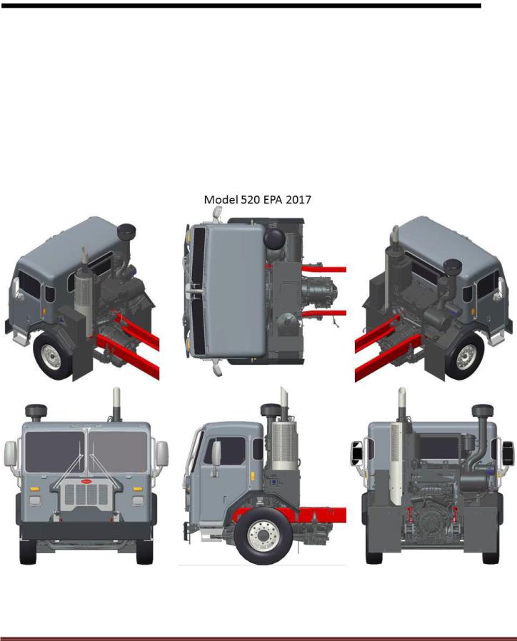
This section includes drawings and charts of the Peterbilt Model 520.
On the pages that follow, detail drawings show particular views of the vehicle; all dimensions are in inches (in). They illustrate important measurements critical to designing bodies of all types. See the “Contents” at the beginning of the manual to locate the drawing that you need.
All heights are given from the bottom of the frame rail.
Note that the Aftertreatment mounting is almost identical other than the use of a DEF tank (for diesels) and different canister/catalyst but both use the same stanchions for mounting BOC.
FIGURE 3-1. Various Views of the Model 520
Peterbilt Motors Company |
3- 2 |

DIMENSIONS |
3 |
EXTERIOR DIMENSIONS |
|
FIGURE 3-2. 520 Cab Dimensions
Notes:
1.Shown with optional HD Air intake Pre-Cleaner
2.Shown with optional front cab guard
3.Door dimension is 33.4”W x 61”H
4.Diesel truck shown, but Natural Gas has same BOC dimension for Aftertreatement.
Peterbilt Motors Company |
3- 3 |

DIMENSIONS |
3 |
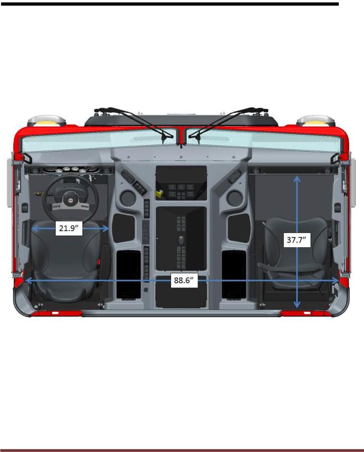
INTERIOR DIMENSIONS
FIGURE 3-3. View Looking Through Cab to the Driver’s Side (LH Steer)
Peterbilt Motors Company |
3- 4 |

DIMENSIONS |
3 |
INTERIOR DIMENSIONS |
|
FIGURE 3-4. View Looking Through the Cab At The RH Drive Standup Version
Peterbilt Motors Company |
3- 5 |
DIMENSIONS |
3 |
INTERIOR DIMENSIONS |
|
FIGURE 3-5. Top View of LH Steer Model
Peterbilt Motors Company |
3- 6 |

DIMENSIONS |
3 |
INTERIOR DIMENSIONS |
|
FIGURE 3-6. Floor Dimensions for LH Floor
Peterbilt Motors Company |
3- 7 |
DIMENSIONS |
3 |
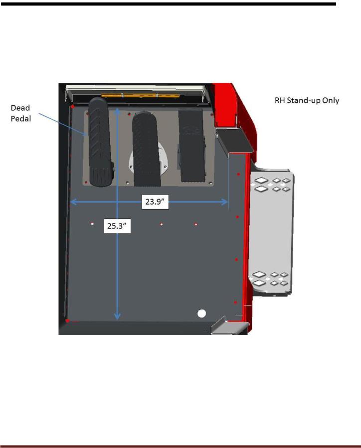
INTERIOR DIMENSIONS |
|
FIGURE 3-7. Passenger Floor RH Stand Up
Peterbilt Motors Company |
3- 8 |
DIMENSIONS |
3 |
FRAME RAILS
Frame rail configurations are shown in Figure 3-8. The under cab area of the 520 frame rails are splayed as shown in Figure 3-9. Frame height, flange and structural values can be found in the Body Mounting Section.
FIGURE 3-8. Frame Rail Configurations
NOTE: The outserted frame section does not extend through the rear suspension area. The outserted frame section does not extend through the splayed area.
Peterbilt Motors Company |
3- 9 |

DIMENSIONS |
3 |
FRAME RAILS |
|
FIGURE 3-9. Model 520 Frame Rail
Peterbilt Motors Company |
3- 10 |

DIMENSIONS |
3 |
FRAME HEIGHT CHARTS |
|
FIGURE 3-4. Frame Height
Peterbilt Motors Company |
3- 11 |

DIMENSIONS |
|
3 |
|
TABLE 3-2. Front Frame Height “A” – 520 |
|
NOTES:
1)Omit spacer block standard.
2)25mm spacer block standard and required.
3)Standard 3-1/2" drop axle heights shown, for 5" drop axles, subtract an additional 1-1/2".
4)Spacer blocks are used by Engineering to obtain level frame and are not options.
5)"A" dimension shown is to bottom of frame rail. Add frame rail height dimension for frame height.
Peterbilt Motors Company |
3- 12 |

DIMENSIONS |
|
|
|
|
|
|
3 |
||
REAR FRAME HEIGHTS "C" |
|
|
|
|
|
|
|
||
|
|
|
TABLE 3-3. Single Drive Suspension Heights |
|
|
|
|
||
|
|
|
|
|
|
Light |
Laden |
|
|
|
Suspension |
|
Rating |
Version |
|
Height |
Height |
|
|
|
LOW AIR LEAF |
|
21,000 lbs. |
Standard |
|
6.8 |
6.5 |
|
|
|
AIR TRAC |
|
20,000 lbs. |
Standard |
|
11.4 |
11.0 |
|
|
|
|
23,000 lbs. |
Standard |
|
11.4 |
11.0 |
|
|
|
|
|
|
|
|
|
||||
|
|
|
20,000 lbs. |
Taper-leaf (3.38" |
|
9.4 |
11.8 |
|
|
|
|
|
saddle) |
|
|
|
|||
|
|
|
|
|
|
|
|
|
|
|
|
|
21,000 lbs. |
Taper-leaf (1.38" |
|
7.4 |
9.8 |
|
|
|
|
|
saddle) |
|
|
|
|||
|
|
|
|
|
|
|
|
|
|
|
|
|
23,000 lbs. |
Multi-leaf (1.38" |
|
8.8 |
11.6 |
|
|
|
|
|
saddle) |
|
|
|
|||
|
REYCO 79KB |
|
|
|
|
|
|
|
|
|
|
26,000 lbs. |
Multi-leaf (1.38" |
|
9.2 |
11.8 |
|
|
|
|
|
|
|
|
|
||||
|
|
|
saddle) |
|
|
|
|||
|
|
|
|
|
|
|
|
|
|
|
|
|
28,000 lbs. |
Multi-leaf (1.38" |
|
9.6 |
12.3 |
|
|
|
|
|
saddle) |
|
|
|
|||
|
|
|
|
|
|
|
|
|
|
|
|
|
31,000 lbs. |
Multi-leaf (1.38" |
|
10.7 |
13.3 |
|
|
|
|
|
saddle) |
|
|
|
|||
|
|
|
|
|
|
|
|
|
|
|
|
|
23K-29K lbs. |
4.38 saddle |
|
12.0 |
10.2 |
|
|
|
|
|
23K-29K lbs. |
4.63 saddle |
|
12.2 |
10.4 |
|
|
|
REYCO 102 |
|
29,000 lbs. |
3.50 saddle |
|
11.7 |
10.0 |
|
|
|
|
31,000 lbs. |
3.50 saddle |
|
12.2 |
10.5 |
|
|
|
|
|
|
|
|
|
||||
|
|
|
31,000 lbs. |
4.38 saddle |
|
12.5 |
10.7 |
|
|
|
|
|
31,000 lbs. |
4.63 saddle |
|
12.7 |
10.9 |
|
|
|
REYCO 102AR (AIR) |
|
17K -23K |
Standard |
|
9.3 |
9.3 |
|
|
|
|
Low |
|
8.3 |
8.3 |
|
|
||
|
|
|
|
|
|
|
|||
Peterbilt Motors Company |
3- 13 |

DIMENSIONS |
|
|
|
|
|
|
3 |
|
|
|
TABLE 3-4. Tandem Drive Peterbilt Suspension Heights |
|
|
|
|||
|
|
|
|
|
Light |
Laden |
|
|
|
Suspension |
|
Rating |
Version |
Height |
Height |
|
|
|
AIR LEAF |
|
38,000 lbs. |
|
12.0 |
11.7 |
|
|
|
LOW AIR LEAF |
|
40,000 lbs. |
|
8.8 |
8.5 |
|
|
|
FLEX AIR |
|
38,000 lbs. |
|
8.8 |
8.5 |
|
|
|
LOW-LOW AIR |
|
40,000 lbs. |
|
6.8 |
6.5 |
|
|
|
LEAF |
|
|
|
|
|||
|
|
|
|
|
|
|
|
|
|
AIR TRAC |
|
40K-46K lbs. |
|
11.4 |
11.0 |
|
|
|
QUADRAFLEX |
|
38,000 lbs. |
Taper-leaf |
10.6 |
8.7 |
|
|
|
|
TABLE 3-5. Tandem Drive Neway Suspension Heights |
|
|
|
|||
|
|
|
|
|
Light |
Laden |
|
|
|
Suspension |
|
Rating |
Version |
Height |
Height |
|
|
|
NEWAY AD |
|
52,000 lbs. |
|
10.0 |
10.0 |
|
|
|
NEWAY ADZ |
|
46K-52K lbs. |
|
10.0 |
10.0 |
|
|
|
|
TABLE 3-6. Tandem Drive Reyco Suspension Heights |
|
|
|
|||
|
|
|
|
|
Light |
Laden |
|
|
|
Suspension |
|
Rating |
Version |
Height |
Height |
|
|
|
|
|
|
1.75 saddle (STD) |
11.7 |
9.8 |
|
|
|
REYCO 102 |
|
40,000 lbs. |
1.38 saddle |
10.2 |
8.3 |
|
|
|
|
|
3.38 saddle |
13.4 |
11.5 |
|
|
|
|
MULTILEAF |
|
|
|
|
|||
|
|
44,000 lbs. |
1.75 saddle (STD) |
11.7 |
9.8 |
|
|
|
|
|
|
|
|
||||
|
|
|
1.38 saddle |
11.5 |
9.7 |
|
|
|
|
|
|
|
|
|
|||
|
|
|
|
|
|
|
|
|
|
REYCO 102AR |
|
34K-40K |
STD LOW |
8.3 |
8.3 |
|
|
|
(AIR) |
|
|
|
||||
|
|
|
|
|
|
|
|
|
Peterbilt Motors Company |
3- 14 |

DIMENSIONS |
|
|
|
|
|
3 |
|
|
TABLE 3-7. Tandem Drive Chalmers Suspension Heights |
|
|
|
|||
|
|
|
|
Light |
Laden |
|
|
|
Suspension |
Rating |
Version |
Height |
Height |
|
|
|
|
|
LOW |
11.1 |
8.9 |
|
|
|
CHALMERS 854 & |
40,000 lbs. |
HIGH |
12.4 |
10.2 |
|
|
|
860 |
X-HIGH |
14.5 |
12.2 |
|
|
|
|
|
|
|
||||
|
|
|
XX-HIGH |
17.2 |
14.9 |
|
|
|
|
|
LOW |
11.3 |
8.9 |
|
|
|
CHALMERS 854 & |
46,000 lbs. |
HIGH |
12.5 |
10.1 |
|
|
|
860 |
X-HIGH |
14.7 |
12.2 |
|
|
|
|
|
|
|
||||
|
|
|
XX-HIGH |
17.3 |
14.9 |
|
|
|
|
|
LOW |
11.3 |
8.9 |
|
|
|
CHALMERS 854 & |
50K-52K |
HIGH |
12.5 |
10.1 |
|
|
|
860 |
X-HIGH |
14.6 |
12.1 |
|
|
|
|
|
|
|
||||
|
|
|
XX-HIGH |
17.3 |
14.8 |
|
|
|
|
|
LOW |
11.2 |
8.8 |
|
|
|
CHALMERS 872 |
46,000 lbs. |
HIGH |
12.5 |
10.3 |
|
|
|
X-HIGH |
14.6 |
12.2 |
|
|
||
|
|
|
|
|
|||
|
|
|
XX-HIGH |
17.3 |
14.9 |
|
|
|
|
|
LOW |
11.2 |
8.8 |
|
|
|
CHALMERS 872 |
50,000 lbs. |
HIGH |
12.5 |
10.3 |
|
|
|
X-HIGH |
14.6 |
12.1 |
|
|
||
|
|
|
|
|
|||
|
|
|
XX-HIGH |
17.3 |
14.8 |
|
|
NOTES: |
|
|
|
|
|
|
|
1) Laden dimension shown with standard restrictor cans. Add 0.7” for #29 High Stability Restrictor Cans.
Peterbilt Motors Company |
3- 15 |

DIMENSIONS |
|
|
|
|
|
|
3 |
|
|
TABLE 3-8. Tandem Drive Hendrickson Suspension Heights |
|
|
|
||||
|
|
|
|
|
Light |
Laden |
|
|
|
Suspension |
Rating |
Version |
Height |
Height |
|
||
|
RT-403 |
40,000 lbs. |
6.00 |
|
9.9 |
8.9 |
|
|
|
7.188 |
(std.) |
11.2 |
10.1 |
|
|
||
|
|
|
|
|
||||
|
RTE-403 |
40,000 lbs. |
6.00 |
|
9.9 |
8.4 |
|
|
|
7.188 |
(std.) |
11.2 |
9.5 |
|
|
||
|
|
|
|
|
||||
|
|
|
12.80 |
|
5.8 |
5.8 |
|
|
|
R-403 |
40,000 lbs. |
15.81 |
(std.) |
8.8 |
8.8 |
|
|
|
|
|
17.60 |
|
10.6 |
10.6 |
|
|
|
|
|
12.25 |
|
9.9 |
9.1 |
|
|
|
RS-403 |
40,000 lbs. |
14.00 |
(std.) |
11.7 |
10.8 |
|
|
|
|
|
15.25 |
|
12.9 |
12.1 |
|
|
|
HMX |
40,000 lbs. |
16.5 (low) |
10.6 |
9.5 |
|
|
|
|
18.5 (std.) |
12.6 |
11.5 |
|
|
|||
|
|
|
|
|
||||
|
HMX |
46,000 lbs. |
16.5 (low) |
10.6 |
9.5 |
|
|
|
|
18.5 (std.) |
12.6 |
11.5 |
|
|
|||
|
|
|
|
|
||||
|
HN462 |
46,000 lbs. |
20.25 |
(high) |
15.0 |
13.3 |
|
|
|
R-463 |
46,000 lbs. |
15.75 |
(std.) |
8.8 |
8.8 |
|
|
|
20.50 |
|
13.5 |
13.5 |
|
|
||
|
|
|
|
|
|
|||
|
|
|
12.25 |
|
9.7 |
8.9 |
|
|
|
RS-463 |
46,000 lbs. |
14.0 (std.) |
11.5 |
10.6 |
|
|
|
|
|
|
15.25 |
|
12.7 |
11.9 |
|
|
|
|
|
6.00 |
|
11.3 |
10.5 |
|
|
|
RT-463 |
46,000 lbs. |
7.188 |
(std.) |
13.0 |
11.4 |
|
|
|
|
|
11.00 |
|
16.3 |
15.2 |
|
|
|
RTE-463 |
46,000 lbs. |
7.188 |
(std.) |
11.6 |
10.2 |
|
|
|
11.00 |
|
15.4 |
14.0 |
|
|
||
|
|
|
|
|
|
|||
|
RS-503 |
50,000 lbs. |
14.0 (std.) |
11.7 |
10.8 |
|
|
|
|
15.25 |
|
12.9 |
12.1 |
|
|
||
|
|
|
|
|
|
|||
|
RT-503 |
50,000 lbs. |
7.188 |
(std.) |
12.1 |
11.1 |
|
|
|
11.0 1 |
16.4 |
15.4 |
|
|
|||
|
|
|
|
|
||||
|
RTE-503 |
50,000 lbs. |
7.188 |
(std.) |
11.6 |
10.2 |
|
|
|
11.00 |
|
15.4 |
14.0 |
|
|
||
|
|
|
|
|
|
|||
|
RS-523 |
52,000 lbs. |
14.0 (std.) |
11.7 |
10.8 |
|
|
|
|
RT-523 , RT-650 |
52K-65K |
7.188 |
(std.) |
12.1 |
11.1 |
|
|
|
11.00 |
|
16.4 |
15.4 |
|
|
||
|
|
|
|
|
|
|||
|
HN522 |
52,000 lbs. |
18.50 |
(std.) |
12.6 |
11.5 |
|
|
|
RS650 |
65,000 lbs. |
15.00 |
(std.) |
12.0 1 |
11.0 2 |
|
|
|
19.00 |
|
16.0 2 |
15.1 2 |
|
|
||
|
|
|
|
|
|
|||
|
R650 * |
65,000 lbs. |
20.25 |
(std.) |
12.5 |
12.5 |
|
|
|
R850 w/70K Meritor |
85,000 lbs. |
20.25 |
|
12.0 |
12.0 |
|
|
|
R850 w/SISU 70K |
20.25 |
|
12.1 |
12.1 |
|
|
|
|
|
|
|
|
||||
|
RS850 w/SISU 70K |
85,000 lbs. |
16.75 |
|
11.5 |
10.6 |
|
|
NOTES: |
|
|
|
|
|
|
|
|
1)With SISU 70k axle subtract 0.39” from light/laden
2)With SISU 70k axle subtract 0.28” from light and 0.39” from laden
Peterbilt Motors Company |
3- 16 |

DIMENSIONS |
|
|
|
|
|
3 |
|
|
|
TABLE 3-9. Tri-Drive Suspension Heights |
|
|
|
|
|
|
|
|
|
|
LOADED |
|
|
|
SUSPENSION |
RATING (lbs.) |
|
LIGHT (in.) |
(in.) |
|
|
|
TRI-DRIVE SUSPENSION |
|
|
|
|
|
|
|
AIR TRAC |
40K-46K |
|
11.4 |
11.0 |
|
|
|
NEWAY ADZ369 |
69,000 |
|
10.0 |
10.0 |
|
|
|
NEWAY ADZ378 |
78,000 |
|
10.0 |
10.0 |
|
|
Peterbilt Motors Company |
3- 17 |
 Loading...